2n Ip Automation Manual En 2.27 3w2y1d
This document was ed by and they confirmed that they have the permission to share it. If you are author or own the copyright of this book, please report to us by using this report form. Report 2z6p3t
Overview 5o1f4z
& View 2n Ip Automation Manual En 2.27 as PDF for free.
More details 6z3438
- Words: 12,902
- Pages: 127
Automation manual for 2N IP intercoms
Configuration Manual Firmware: Version:
2.27 2.27
www.2n.cz
The 2N TELEKOMUNIKACE a.s. is a Czech manufacturer and supplier of telecommunications equipment.
The product family developed by 2N TELEKOMUNIKACE a.s. includes GSM gateways, private
branch
exchanges
(PBX),
and
door
and
lift
communicators.
2N
TELEKOMUNIKACE a.s. has been ranked among the Czech top companies for years and represented a symbol of stability and prosperity on the telecommunications market for almost two decades. At present, we export our products into over 120 countries worldwide and have exclusive distributors on all continents.
2N
® is a ed trademark of 2N TELEKOMUNIKACE a.s. Any product and/or other
names mentioned herein are ed trademarks and/or trademarks or brands protected by law.
2N TELEKOMUNIKACE a.s. isters the FAQ database to help you quickly find information and to answer your questions about 2N products and services. On www. faq.2n.cz you can find information regarding products adjustment and instructions for optimum use and procedures „What to do if...".
2N TELEKOMUNIKACE a.s. hereby declares that the 2N product complies with all basic requirements and other relevant provisions of the 1999/5/EC directive. For the full wording of the Declaration of Conformity see the CD-ROM (if enclosed) or our website at www.2n.cz.
This device complies with part 15 of the FCC Rules. Operation is subject to the following two conditions: (1) This device may not cause harmful interference, and (2) this device must accept any interference received, including interference that may cause undesired operation.
The 2N TELEKOMUNIKACE a.s. is the holder of the ISO 9001:2009 certificate. All development, production and distribution processes of the company are managed by this standard and guarantee a high quality, technical level and professional aspect of all our products.
Content:
1. and Symbols 2. 2N® IP Automation Configuration 3. Events 4. Actions 5. Conditions 6. Utilities 7. Available Digital Inputs and Outputs 8. Examples of Use
2N TELEKOMUNIKACE a.s., www.2n.cz
4/127
1. and Symbols
The following symbols and pictograms are used in the manual: Safety Always abide by this information to prevent persons from injury.
Warning Always abide by this information to prevent damage to the device.
Caution Important information for system functionality.
Tip Useful information for quick and efficient functionality.
Note Routines or advice for efficient use of the device.
2N TELEKOMUNIKACE a.s., www.2n.cz
5/127
2. 2N® IP Automation Configuration
2N IP intercoms provide flexible setting options depending on the 's requirements. If the standard setting options (switch/call settings, e.g.) are insufficient for the intended use, apply a special programmable interface – Automation. Typically, Automation is helpful for applications that require rather complex interconnection with the third parties' systems. Note Automation works only with a valid Enhanced Integration or Gold licence key.
Some 2N IP intercom models are equipped with a number of digital inputs and outputs, most of which can be configured like standard 2N IP intercom switches (refer to the Switches subsection). You can make use of all of these Automation inputs and outputs in variable combinations. Automation helps you combine the Events arising in the system (such as key pressing, RFID card use, digital input status change, etc.) with specific Actions (such as digital output activation, sound playing, call, etc.) as necessary. Moreover, the execution of actions can be bound by selected Conditions (time profile state, logic input state, e. g.).
2N TELEKOMUNIKACE a.s., www.2n.cz
6/127
The figure above shows a typical interconnection of the Event, Action and Condition blocks. It holds true in general that an action is always tied with a selected event and is executed when a selected condition is met. The condition is optional and if none is selected, the action is executed whenever the assigned event occurs. Automation defines a number of events, actions and conditions to be further set. Refer to the subsections below for the full list. The example shown in the figure above can be interpreted as follows: The SetOutput action (digital output setting) is executed if the InputChanged event (logic input1 change from log 0 to log 1) arises and the Profile (active profile 1) condition is met.
2N TELEKOMUNIKACE a.s., www.2n.cz
7/127
Automation Control Bookmark Function – 2N IP intercom allows up to 30 blocks at 5 independent pages to be created and interconnected (regardless of the block type – events, actions and conditions). Multiple actions can be assigned to an event or condition. Thus, you can create 15 actions and assign them to 15 events or create 29 actions and assign them to 1 event, for example. Enabled – function enable Name – function name State – function state: Started/Stopped/Empty/Error Action – click
to set the function and
2N TELEKOMUNIKACE a.s., www.2n.cz
to delete the function.
8/127
Automation Controls Refer to the figure below for an empty Automation function.
Function block column – includes four groups of function blocks: Events, Actions, Conditions, Utilities. Drag and drop the items to the desktop. Toolbar – includes function controls Pictogram
Description function name
function editing mode
function block moving mode
help mode for function blocks. Click a block to display the block help.
magnification
zoom out/in
import/export
2N TELEKOMUNIKACE a.s., www.2n.cz
9/127
block deletion
Automation manual reference
save
quit function editing
The desktop helps you place and interconnect the function blocks.
2N TELEKOMUNIKACE a.s., www.2n.cz
10/127
Block Parameter Settings Select the required Event (Event.xxx), Action (Action.xxx) or Condition (Condition. xxx) in the Object type column. Set one or more parameters for the blocks in the respective row of the Parameters column – refer to the block describing subsections below for the ed parameters. Enter the block parameter value into the appropriate field below the parameter name. The changes will not be executed until you press the Save button in the right-hand upper corner of the page . Click Save to save the changes. If the function setting is correct, the information is displayed in a green field. If incorrect (invalid name/value or missing mandatory parameter), error information is displayed in a red field. Wrong values are marked with and the parameter name is red. Automation works only if all the available blocks are configured properly. If not, Automation is in the Error state. Most of the blocks include parameters (Event, Condition, StartEvent, e.g.) that refer to other blocks. To interconnect the blocks, click on the output of one block and drag and drop it to the input of another. Tip The Upper-Lower case need not be respected in the parameter names. Some block parameters are optional. If you do not enter an optional parameter in the block definition, the default value will be applied.
2N TELEKOMUNIKACE a.s., www.2n.cz
11/127
Use of Output parametres The event block output parameters help transfer additional information between blocks – send the detected card ID via HTTP to another device, use the parameters received via HTTP for setting parameters of a tied action and so on. Use Formatter for this purpose. The output parametres values are updated whenever an event is generated. A value can be used for other blocks too thanks to interconnection.
To move an output parametr from Events to Formatter, connect the output parameter with Param1. This output parameter is only available via addressing in the Format field {outputparameter_number} . Example of Formatter use for ID card transfer: Format: http://1.1.1.1./card={1 } Param1: connected to CardEntered card block output Text: connected to SendHttpRequest Uri block input Every event defines the TimeStamp and Count output parameters. TimeStamp contains encoded date and time of the last event generation in the Unix Time format (second count from 00:00:00 1.1.1970). Count contains the count of event generations after the device start or last block configuration change. The output parameter increases by 1 after each event generation. Refer to the following subsections for more output parameters with specific functions.
2N TELEKOMUNIKACE a.s., www.2n.cz
12/127
Tip The Upper/Lower case is not be respected in the output parameters names.
Caution You cannot use the output parameters in the block relation defining parameters, i.e. Event, Condition, etc.
2N TELEKOMUNIKACE a.s., www.2n.cz
13/127
Caution In order to ensure the full functioning and guaranteed outputs we strongly recommend a verification of the timeliness of version of product or facility already during the installation process. The customer takes into consideration that the product or facility can achieve the guaranteed outputs and be fully operational pursuant to the producer’s instructions only by using the most recent version of product or facility, which has been tested for full interoperability and has not been determined by the producer as incompatible with certain versions of other products, only in conformity with the producer’s instructions, guidelines, manual or recommendation and only in conjunction with suitable products and facilities of the other producers. The most recent versions are available on the website https://www.2n.cz/cs_CZ/, or specific facilities, depending on their technical capacity, allow updating in the configuration interface. Should the customer use any other version of product or facility than the most recent one, or the version that has been determined by the producer as incompatible with certain versions of other producers’ products of facilities, or the product or facility in a way incompatible with the producer’s instructions, guidelines, manual or recommendation or in conjunction with unsuitable products or facilities of the other producers, he or she is aware of all potential limitations of functionality of such a product or facility and all relating consequences. Should the customer use any other than the most recent version of the product or facility, or the version that has been that has been determined by the producer as incompatible with certain versions of other producers’ products of facilities, or the product or facility in a way incompatible with the producer’s instructions, guidelines, manual or recommendation or in conjunction with unsuitable products or facilities of the other producers, he or she agrees that the company 2N TELEKOMUNIKACE a. s. is not liable neither for any limitation of such a product’s functionality, nor for any damage, loss or injury relating to such a potential limitation of functionality.
2N TELEKOMUNIKACE a.s., www.2n.cz
14/127
3. Events
Automation defines the following types of events: AudioLoopTest – audio test performed CallStateChanged – call state changed CardEntered – RFID card entered CardHeld – RFID card held CodeEntered – numeric code entered Delay – delay defined DoorOpenTooLong – excessively long door opening DtmfEntered – DTMF numeric code detected in call DtmfPressed – DTMF code received in call FingerEntered – fingerprint reader authentication HttpTrigger – HTTP command received InputChanged – digital input changed KeyPressed – key pressed KeyReleased – key released LockdownStateChanged – emergency lockdown MobKeyEntered – Bluetooth reader authentication MotionDetected – motion detected by the camera MulticastTrigger – command for multiple devices received OnvifVirtualOutputChanged – event received from VMS NoiseDetected – noise detected by the microphone RegistrationStateChanged – SIP registration state changed Rebooted – device start/restart detected SilentAlarm – silent alarm activated Time – specific time (alarm clock) Timer – periodical event timer UnauthorisedDoorOpen – unauthorised door opening Authorized – authorisation OutputChanged – output changed
2N TELEKOMUNIKACE a.s., www.2n.cz
15/127
OutputChanged – output changed See below for details on the events and their Input parameters and use.
2N TELEKOMUNIKACE a.s., www.2n.cz
16/127
AudioLoopTest The AudioLoopTest block defines the event generated after the loudspeaker and microphone test (Audio Loop Test) is performed. The subsequent actions are executed based on the test result.
Input parameters Result – this parameter specifies the required test result. Valid values: any – the event is generated whenever the test is performed (regardless of the result). ed – the event is generated whenever the test is successful. failed – the event is generated whenever the test fails. The parameter is optional, the default value is failed.
Output parameters Event – the Event output to invoke the connected Event or Action.
Example An event generated after the audio loop test if the test result is negative (i.e. the microphone or loudspeaker is out of order):
2N TELEKOMUNIKACE a.s., www.2n.cz
17/127
CallStateChanged The CallStateChanged block defines the event generated by a call state change (call ringing, call connection, call termination, etc.).
Input parameters State – define the call state change. Valid values: ringing – ringing start connected – successful call connection terminated – call termination. Direction – define the call direction. Valid values: incoming – incoming calls outgoing – outgoing calls any – both directions. The parameter is optional, the default value is any. Number – define the identifier (phone number, IP address) to be matched against the caller's identifier to make the event happen. Enter multiple commaseparated numbers if necessary. A non-completed value is the same as any. This parameter is optional, the default value is any.
Output parameters Event – the Event output to invoke the connected Event or Action. State – the detected call state which generated this event. The options correspond to the State parameter. Direction – the detected call direction which generated this event. The options are incoming or outgoing. Uri – the output containing the opponent's complete SIP uri.
2N TELEKOMUNIKACE a.s., www.2n.cz
18/127
Example Event generated by answering a call from number 1234:
2N TELEKOMUNIKACE a.s., www.2n.cz
19/127
CardEntered The CardEntered block defines the event generated by tapping (swiping) of the RFID card with the defined ID (for RFID card reader models only).
Input parameters Card – define the RFID card ID; refer to the Card Reader subsection in the Configuration Manual. Valid values: valid – any valid card (included in the intercom card list) invalid – any invalid card any – any valid or invalid card < > (empty value) – the event will not be generated Or, complete the card ID manually. SuppressTones – suppress sound signalling initiated by detection of an invalid card. The parameter is optional. Valid values: disabled – tones are not suppressed enabled – tones are suppressed (default value). Reader – define the card reader / module to be used Valid values: internal_cardreader – internal card reader (2N
®
external_cardreader – external card reader (2N
IP Vario, Force)
® IP Vario, Force)
any – any reader / module Or, complete the module name manually as configured in the Module Name parameter in the Hardware / Extenders / Modules / Used module menu (2N
® IP Verso).
The parameter is optional, the default value is any. Direction – define direction Valid values: in – reader with defined incoming direction out – reader with defined outgoing direction any – both directions The parameter is optional, the default value is any.
2N TELEKOMUNIKACE a.s., www.2n.cz
20/127
Output parameters Event – the Event output to invoke the connected Event or Action. Card – ID of the detected card which was the last to generate this event. Direction – configured direction at the card reader (in, out, any). Reader – name of the module which was used ( internal_cardreader, external_cardreader, <module_name>).
Example Event generated by entering of the card with ID 0012456:
2N TELEKOMUNIKACE a.s., www.2n.cz
21/127
CardHeld The CardHeld block defines the event generated by holding of the RFID card with the defined ID (for RFID card reader models only). The event is generated by holding the RFID card for 4s at the RFID card reader.
Input parameters Card – define the RFID card ID; refer to the Card Reader subsection in the Configuration Manual. Valid values: valid – any valid card (included in the intercom card list) invalid – any invalid card any – any valid or invalid card < > (empty value) – the event will not be generated Or, complete the card ID manually. SuppressTones – suppress sound signalling initiated by detection of an invalid card. The parameter is optional. Valid values: disabled – tones are not suppressed enabled – tones are suppressed (default value). Reader – define used card reader / module Valid values: internal_cardreader – internal card reader (2N
®
external_cardreader – external card reader (2N
IP Vario, Force)
®
IP Vario, Force)
any – any reader / module Or, complete the module name manually as configured in the Module Name parameter in the Hardware / Extenders / Modules / Used module menu (2N® IP Verso). The parameter is optional, the default value is any. Direction – define direction Valid values: in – reader with defined incoming direction out – reader with defined outgoing direction any – both directions The parameter is optional, the default value is any.
2N TELEKOMUNIKACE a.s., www.2n.cz
22/127
Output parameters Event – the Event output to invoke the connected Event or Action. Card – ID of the detected card which was the last to generate this event. Reader – name of the module which was used ( internal_cardreader, external_cardreader, <module_name>). Direction – configured direction at the card reader (In, Out, Unspecified).
Example Event generated by holding of the card with ID 0012456:
2N TELEKOMUNIKACE a.s., www.2n.cz
23/127
CodeEntered The CodeEntered block defines the event generated by entering of a numeric code and confirmation with the * key (for numeric keypad models only).
Input parameters Code – define the numeric code. Valid values: numeric code – 12345, e.g. valid – any valid code invalid – any invalid code any – any valid or invalid code < > (empty value) – the event will not be generated SuppressTones – suppress sound signalling initiated by receiving of an invalid numeric code. The parameter is optional. Valid values: disabled – tones are not suppressed enabled – tones are suppressed (default value).
Output parameters Event – the Event output to invoke the connected Event or Action. Code – the received numeric code which was the last to generate this event.
2N TELEKOMUNIKACE a.s., www.2n.cz
24/127
Example Event generated by entering code 12345* on a keypad:
2N TELEKOMUNIKACE a.s., www.2n.cz
25/127
Delay The Delay block defines the event generated with a defined delay after another specified event. Define this event to delay the response to the other event by a defined time interval (Delay).
Input parameters Start – define the event that starts the delay. Stop – define the event that stops the delay. The parameter is optional. Delay – define the delay time. It is only possible to enter a numerical value, not a value from an output parameter produced by other events. Example of valid values: 10 – 10 seconds (units are unnecessary) 10s – 10 seconds 100ms – 100 milliseconds.
Output parameters Event – the Event output to invoke the connected Event or Action.
Example Event generated 1s after the rise of event on row 1:
2N TELEKOMUNIKACE a.s., www.2n.cz
26/127
DoorOpenTooLong The DoorOpenTooLong block defines the event generated in case the door stays open longer than as set.
Input parameters State – state of the door sensor that generates the event. Valid values: Start – event start End – event end
Output parameters Event – output for generating of the assigned Event or Action.
Example The DoorOpen event is longer than set.
2N TELEKOMUNIKACE a.s., www.2n.cz
27/127
DtmfEntered The DtmfEntered block defines the event that is generated by entering of a numeric code confirmed with the * key in DTMF in an incoming or outgoing call.
Input parameters Code – define the numeric code. Valid values: numeric code – 12345, e.g. < > (empty value) – the event will not be generated SuppressTones – suppress sound signalling initiated by receiving of an invalid DTMF code. The parameter is optional. Valid values: disabled – tones are not suppressed enabled – tones are suppressed (default value).
Output parameters Event – the Event output to invoke the connected Event or Action. Code – the detected received numeric code which was the last to generate this event.
Example Event generated upon detection of DTMF code 12345*
2N TELEKOMUNIKACE a.s., www.2n.cz
28/127
DtmfPressed The DtmfPressed block defines the event that is generated when the defined or any DTMF code is received from the defined group. DTMF codes are detected both in incoming and outgoing calls.
Input parameters Key – define the DTMF code (or DTMF code group). If this parameter is not completed, the event is generated whenever any DTMF code is detected (default value: Any). Valid values: 0, 1, 2, 3, 4, 5, 6, 7, 8, 9, *, #, A, B, C, D any for any key (default value). Separate the values with a comma to specify a group of codes. Direction – define the call direction. Valid values: incoming – incoming calls outgoing – outgoing calls any – both directions The parameter is optional, the default value is any.
Output parameters Event – the Event output to invoke the connected Event or Action. Pressed Key – the recorded received DTMF code which was the last to generate the event. The DTMF is stored in the Key parameter format.
2N TELEKOMUNIKACE a.s., www.2n.cz
29/127
Example Event generated upon detection of DTMF code #:
2N TELEKOMUNIKACE a.s., www.2n.cz
30/127
FingerEntered The FingerEntered block defines the event generated by identifying a known fingerprint on the fingerprint reader (for fingerprint reader equipped devices only).
Input parameters Fingerprint - define validity of the entered fingerprint. Valid values: valid - the fingerprint belongs to a invalid - the fingerprint is unknown any - any entered fingerprint Finger - define one of two fingerprints stored for the . Valid values: any - any fingerprint of the F1 - the fingerprint was defined as "F1" for Automation at the Fingerprint enrolment F2 - a fingerprint was defined as "F2" for Automation at the Fingerprint enrolment Suppress Tones - suppress sound signalling initiated by detection of an invalid (fingerprint). The parameter is optional. Valid values: disabled - tones are not suppressed enabled - tones are suppressed (default value).
Output parameters Event – the Event output to invoke the connected Event or Action. – UUID of the whose fingerprint has generated this event.
2N TELEKOMUNIKACE a.s., www.2n.cz
31/127
Example An event generated by valid entering of a fingerprint on a biometric reader.
2N TELEKOMUNIKACE a.s., www.2n.cz
32/127
HttpTrigger The HttpTrigger block defines the event generated by receiving of an HTTP command from the intercom HTTP server. When the HTTP command http://ip_addr/enu/trigger /id is received, the event will be generated whose ID matches the value that follows 'trigger/' in the HTTP command. The intercom sends a simple reply to this request (200 OK).
Input parameters Name – define a unique HTTP command identifier including alphabetical characters and digits.
Output parameters Event – the Event output to invoke the connected Event or Action. Params – parameters sent in the SendHttpRequest block or the command coming to the 2N IP intercom. The HttpTrigger event is always generated by the HTTP command which can carry a list of Input parameters as included in the URI command. http://ip_address/enu/trigger/id?param1=value1¶m2=value2 The list of Input parameters follows the ? character. Each parameter must include the name and value separated with the = character. If the list includes more Input parameters than one, & is used as the separator. The HTTP-received Input parameters are available as HttpTrigger block Output parameters. The output parameters name equals to the name of the parameter transferred - $(line.param1) a $(line.param2).
2N TELEKOMUNIKACE a.s., www.2n.cz
33/127
Example Event generated by receiving of the following HTTP command: http://ip_addr/enu /trigger/opendoor :
2N TELEKOMUNIKACE a.s., www.2n.cz
34/127
InputChanged The InputChanged block defines the event generated by a change of the logic level on the defined digital input.
Input parameters Input – define the logic input. Valid values: tamper – tamper switch input input1 – digital input 1 input2 – digital input 2 cr_input1 – digital input 1 on card reader cr_input2 – digital input 2 on card reader. There may be different lists of valid values for different 2N IP intercom models; refer to the Available Digital Inputs and Outputs subsection. Edge – define the detected change on the digital input. Valid values: falling – falling edge, change from log. 1 to log. 0 rising – rising edge, change from log. 0 to log. 1. The parameter is optional, the default value is rising.
Output parameters Event – the Event output to invoke the connected Event or Action. Output – the detected ID of the input whose change was the last to generate this event. The options correspond to the Input parameter values. Edge – the detected edge change which was the last to generate this event. The options are falling or rising.
2N TELEKOMUNIKACE a.s., www.2n.cz
35/127
Example Event generated by disconnection of the tamper switch (device opening):
2N TELEKOMUNIKACE a.s., www.2n.cz
36/127
KeyPressed The KeyPressed block defines the event generated by pressing of the defined key or any key from the defined group.
Input parameters Key – define the key or a key group. If this parameter is not completed, the event is generated upon pressing of any key (default value: any). Valid values: 0, 1, 2, 3, 4, 5, 6, 7, 8, 9, *, # for numeric keypad buttons %1, %2, .., %999 for quick dial buttons any for any button (default value). Separate the values with a comma while defining more keys than one. SuppressTones – suppress sound signalling initiated by pressing of a nonprogrammed quick dial button. The parameter is optional. Valid values: disabled – tones are not suppressed enabled – tones are suppressed (default value)
Output parameters Event – the Event output to invoke the the connected Event or Action. Pressed Key – the recorded code of the key which was the last to generate this event. The key code is stored in the Key parameter format.
Example Event generated by pressing of # and quick dial button 3 or 4:
2N TELEKOMUNIKACE a.s., www.2n.cz
37/127
KeyReleased The KeyReleased block defines the event generated by releasing of the defined pressed key or any key from the defined group. Note Vario model: the event is generated whenever the button is pressed, the functionality is the same as with KeyReleased.
Input parameters Key – define the key or a key group. If this parameter is not completed, the event is generated upon releasing of any key (default value: any). Valid values: 0, 1, 2, 3, 4, 5, 6, 7, 8, 9, *, # for numeric keypad buttons %1, %2, .., %999 for quick dial buttons any for any button (default value). Separate the values with a comma while defining more keys than one.
Output parameters Event – the Event output to invoke the connected Event or Action. Released Key – the recorded code of the key which was the last to generate this event. The key code is stored in the Key parameter format.
Example Event generated by releasing of 1 and quick dial button 2:
2N TELEKOMUNIKACE a.s., www.2n.cz
38/127
LockdownStateChanged The LockdownStateChanged block defines the condition to be met when the emergency lockdown is active.
Input parameters Door – set the age direction. Valid values: any – any type of event entry – entry exit – exit State – set the door sensor state to generate the event. Valid values: any – any type of event unlocked – unlocked locked – locked
Output parameters Event – Event/Action generating output. Door – age direction: entry and exit. State – event generating emergency lockdown: any, unlocked and locked.
Example The event generated when the emergency lockdown is active.
2N TELEKOMUNIKACE a.s., www.2n.cz
39/127
MobKeyEntered The MobkeyEntered block defines the event generated by reading a known Mobile Key on the Bluetooth reader (for the devices with Bluetooth reader only).
Input parameters MobKey – define the current Mobile Key validity. Valid values: valid - the Mobile Key belongs to a invalid - the Mobile Key is unknown any - any entered Mobile Key. Suppress Tones - suppress sound signalling initiated by detection of an invalid (Mobile Key). The parameter is optional. Valid values: disabled - tones are not suppressed enabled - tones are suppressed (default value).
Output parameters Event – the Event output to invoke the connected Event or Action. – UUID of the whose Mobile Key has generated this event.
2N TELEKOMUNIKACE a.s., www.2n.cz
40/127
Example An event generated by valid reader authorisation.
2N TELEKOMUNIKACE a.s., www.2n.cz
41/127
MotionDetected The MotionDetected block defines the event generated at motion detection. Motion can be detected by the internal camera only. The Motion detection Input parameters are configured in the Hardware / Camera / Internal Camera menu, section Motion Detection Settings.
Input parameters State – define whether the start or the end of the motion should be detected. Valid values: start – start of the motion end – end of the motion The parameter is optional, the default value is start.
Output parameters Event – the Event output to invoke the connected Event or Action.
Example Event generated at the start of the motion.
2N TELEKOMUNIKACE a.s., www.2n.cz
42/127
MulticastTrigger The MulticastTrigger block defines the event generated by receiving of a command sent via SendMulticastRequest. The request is a message sent by UDP to a multicast address (235.255.255.250:4433) and can thus be received by multiple devices at the same time. The message includes the command ID (Command parameter) and additional optional Input parameters. The message can be -secured ( parameter).
Input parameters Command – define the command ID to distinguish the command types. The MulticastTrigger block responds to the SendMulticastRequest action only if the command identifier is the same. Any text containing the A-Z, a-z and 0-9 characters can be used for identification. The Upper/Lower case must be respected in the command name. CheckTime – enable/disable the check of the command receiving time against the time value included in the command message to eliminate attacks caused by repeating of an already processed message. Synchronised time (via the NTP server) on all command sending and receiving devices is required for this function. Valid values: disabled – message time is not checked enabled – message time is checked (enhanced security). The parameter is optional, the default value is 0. – define the to secure the command against unauthorised access. The must match the value defined in the SendMulticastRequest action to which MulticastTrigger is expected to respond.
Output parameters Event – the Event output to invoke the connected Event or Action. Params – parameters sent in the SendMulticastRequest Action. The MulticastTrigger event is generated whenever a mass command including the list of Input parameters (Params parameter, MulticastRequest action) is received. Each of the Input parameters has a -defined unique name and is available as an Output parameter of the same name in the MulticastTrigger block. Example: Suppose a mass command generated by the MulticastRequest action is received, in which Params=“AAA=123” is included. The MulticastTrigger event which processes this command will automatically include value 123 for the AAA output parameter. This output parameter can be referred to in the interconnected blocks.
2N TELEKOMUNIKACE a.s., www.2n.cz
43/127
Example Event generated by receiving of a mass opendoor command:
2N TELEKOMUNIKACE a.s., www.2n.cz
44/127
OnvifVirtualOutputChanged The OnvifVirtualOutputChanged block helps transmit events from VMS to a 2N IP intercom.
Input parameters Port – set the port to set VMS. Valid values: 50–54. Edge – define the change detected on the virtual input. Valid values: falling – falling edge, change from log 1 to log 0 rising – rising edge, change from log 0 to log 1 The parameter is optional, the default value is rising.
Output parameters Event – Event/Action generating output. Port – port value changed from VMS. Valid values: 50–54. Edge – the last virtual input change that generated this event. Valid values: falling or rising.
Example The event generated when the virtual port value changes.
2N TELEKOMUNIKACE a.s., www.2n.cz
45/127
NoiseDetected The NoiseDetected block defines the event generated at noise detection. Noise can be detected by the internal microphone only. The noise detection Input parameters are configured in the Hardware / Audio menu, section Noise Detection Settings.
Input parameters State – define whether the start or the end of the noise should be detected. Valid values: start – start of the noise end – end of the noise The parameter is optional, the default value is start.
Output parameters Event – the Event output to invoke the connected Event or Action.
Example Event generated at the start of the noise
2N TELEKOMUNIKACE a.s., www.2n.cz
46/127
RegistrationStateChanged The RegistrationStateChanged block defines the event generated at a SIP registration state change. Set the SIP registration in Services / SIP 1 and SIP 2. Registration gets changed whenever the intercom is switched on, configuration is changed or registrar connection gets lost, for example.
Input parameters – select the for which events are to be monitored. Valid values: 1 – 1 2 – 2 Any – any The parameter is optional, the default value is Any. State – set the registration state that generates the event. Valid values: Uned – intercom not ed ing – registration in progress ed – intercom is ed Uning – unregistration in progress Any – any state change The parameter is optional, the default value is Any.
Output parameters Event – the Event output to invoke the connected Event or Action. – select the for which events are to be monitored. State – set the registration state that generates the event.
2N TELEKOMUNIKACE a.s., www.2n.cz
47/127
Example Event generated when the intercom has been uned (whenever the registrar failed to respond to a periodical registration request):
2N TELEKOMUNIKACE a.s., www.2n.cz
48/127
Rebooted The Rebooted block defines the event generated in case the device is started /restarted.
Input parameters This block has no Input parameters.
Output parameters Event – output for generating of the assigned Event or Action. Time – device start/restart time. Reason – reboot reason.
Example The event generated at the device startup.
2N TELEKOMUNIKACE a.s., www.2n.cz
49/127
SilentAlarm The SilentAlarm block defines the event generated upon the silent alarm start. Silent alarm can be started by entering a code higher by 1 than the switch code. If, thus, a is assigned switch code 123, silent alarm is started with 124.
Input parameters This block has no Input parameters.
Output parameters Event – the Event output to invoke the connected Event or Action.
Example Event generated by entering code 112 if some of the s is assigned code 111.
2N TELEKOMUNIKACE a.s., www.2n.cz
50/127
Time The Time block defines the event generated every day at a specific time (alarm clock). To limit validity of this event for some days only, use the condition Condition. ProfileState at the started action and specify requested days in the used time profile.
Input parameters Time – define time to start the event. Time is entered in hh:mm format.
Output parameters Event – the Event output to invoke the connected Event or Action.
Example Event generated every day at 17:30.
2N TELEKOMUNIKACE a.s., www.2n.cz
51/127
Timer The Timer block defines the event generated with a defined delay after another specified event with a defined count of repetitions. Define this event to delay the response to the other event by a defined time interval or execute the response several times.
Input parameters Start – define the timer starting event (i.e. the row number on the Automation tab on which the event is defined). The parameter is optional. If no value is completed, the timer will be started automatically. Stop – define the timer stopping event (i.e. the row number on the Automation tab on which the event is defined). When StopEvent is executed, the timer will stop and will be restarted by StartEvent only. This parameter is optional. Period – define the timer period. Example of valid values: 10 – 10 seconds (units are unnecessary) 10s – 10 seconds 100ms – 100 milliseconds. The minimum period is 100ms. Count – define the count of repetitions. The parameter is optional and the default value is 0, which means that the count of timer generated events is unlimited. Value 1 makes the timer behave as a Delay.
Output parameters Event – the Event output to invoke the connected Event or Action.
2N TELEKOMUNIKACE a.s., www.2n.cz
52/127
Example Event generated three times in 1s intervals after the rise of event on row 1:
2N TELEKOMUNIKACE a.s., www.2n.cz
53/127
UnauthorisedDoorOpen The UnauthorisedDoorOpen block defines the event generated whenever an unauthorised door opening is detected.
Input parameters State – state of the door sensor that generates the event. Valid values: Start – event start End – event end
Output parameters Event – output for generating of the assigned Event or Action.
Example The event generated at an unauthorised door unlocking.
2N TELEKOMUNIKACE a.s., www.2n.cz
54/127
Authorized The Authorized block defines the event generated at authorisation by any access method (code, PIN, RFID, Bluetooth, fingerprint).
Input parameters – define the / list. If no value is completed (default value), the is irrelevant.
Output parameters Event – Event/Action generating output. – identification that generated this event.
Example The event generated by Victoria Black authorisation.
Caution The parameter is limited to up to 10 s.
2N TELEKOMUNIKACE a.s., www.2n.cz
55/127
OutputChanged The OutputChanged defines the event generated at an output change.
Input parameters Output – define the logical input. Valid values: relay1 – relay 1 on basic unit relay2 – relay 2 on basic unit output1 – output 1 on basic unit output2 – output 2 on basic unit The list of valid values can be different for each of the 2N IP intercom models, refer to Available Digital Inputs and Outputs. Edge – define the detected output change. Valid values: falling – falling edge, change from log 1 to log 0 rising – rising edge, change from log 0 to log 1 The
parameter
is
optional,
the
default
value
is
rising.
Output parameters Event – Event/Action generating output. Output – detected ID of the input whose change was the last to generate this event. The available values correspond to the Input values. Edge – detected change of the output that was the last to generate this event. The available values are falling or rising.
2N TELEKOMUNIKACE a.s., www.2n.cz
56/127
Example The event generated by the change of the relay 1 output.
2N TELEKOMUNIKACE a.s., www.2n.cz
57/127
4. Actions
Automation – defines the following types of actions: ActivateSwitch – switch activation SetOutput – digital output state setting BeginCall – outgoing call setup AnswerCall – incoming call answer EndCall – call termination SendHttpRequest – HTTP command sending SendMulticastRequest – command sending to multiple devices PlaySound – sound playing StartMulticastSend – audio stream sending start StopMulticastSend – audio stream sending stop StartMulticastRecv – audio stream receiving start StopMulticastRecv – audio stream receiving stop SetCameraInput – camera input selection ControlRtpStream – call RTP stream control LogEvent – event logging to the syslog server SendDtmf – DTMF codes sending SendEmail – email sending SetOnvifVirtualInput – virtual input for ONVIF SendWiegandCode – code sending to the Wiegand bus SnapshotToFtp – snapshot to the FTP server StartAutoUpdate – firmware and configuration AutoUpdate OpenDoor – light and sound signalling of access via a card reader
2N TELEKOMUNIKACE a.s., www.2n.cz
58/127
ActivateSwitch The ActivateSwitch block defines the action necessary for activation of the intercom switch as configured in the Switch 1–4 tags. The activity to be performed depends fully on the particular switch settings (digital output activation, HTTP command sending, etc.). Switch deactivation is controlled by the switch settings too.
Parameters Event – define the event to launch the action. Condition – define the condition to be met to execute the action. This parameter is optional. Switch – define the switch to be activated (1 to 4). State – define the state of the bistable switch (parameter does not apply for the monostable switch mode). Valid values: on – the switch is activated. off – the switch is deactivated. toggle – the switch is toggled. The parameter is optional, the default value is on.
Example Activate switch 1 if the event defined on row 2 arises and the condition defined on row 3 is met:
2N TELEKOMUNIKACE a.s., www.2n.cz
59/127
SetOutput The SetOutput block defines the action necessary for setting of the intercom output to the required level.
Parameters Event – define the event that launches the action. Condition – define the condition to be met to execute the action. This parameter is optional. Output – define the output to be set. Valid values: relay1 – relay 1 on basic unit relay2 – relay 2 on basic unit output1 – output 1 on basic unit output2 – output 2 on basic unit There may be different lists of valid values for different 2N IP intercom models; refer to the Available Digital Inputs and Outputs subsection. Level – define the required output level. This parameter is optional. Valid values: lo – output deactivation hi – output activation (default value).
Example Activate Output1 if the event defined on row 2 arises:
2N TELEKOMUNIKACE a.s., www.2n.cz
60/127
BeginCall The BeginCall block defines the action necessary for establishing of an outgoing call to the defined telephone number, SIP URI or number included in the intercom phone book.
Parameters Event – define the event to launch the action. Condition – define the condition to be met to execute the action. This parameter is optional. Number – define the phone number to be called (if 2N IP intercom is ed to the PBX). Uri – define the SIP URI to be called: sip:@domain. – define the to be called. Device – define the 2N
® IP Mobile application to be called: device_name.
Enter just one of the above mentioned parameters (Number, Uri, or Device ).
Example Establish an outgoing call if the event defined on row 2 arises:
2N TELEKOMUNIKACE a.s., www.2n.cz
61/127
AnswerCall The AnswerCall block defines the action necessary for answering of an incoming call. In case no call is coming or the incoming call is not ringing, the action will not initiate any activity.
Parameters Event – define the event to launch the action. Condition – define the condition to be met to execute the action. This parameter is optional.
Example Answer a call if the event defined on row 2 arises:
2N TELEKOMUNIKACE a.s., www.2n.cz
62/127
EndCall The EndCall block defines the action necessary for termination of the currently made call. In case there is no active call via the intercom, the action will not initiate any activity.
Parameters Event – define the event to launch the action. Condition – define the condition to be met to execute the action. This parameter is optional.
Example Terminate a call if the event defined on row 2 arises:
2N TELEKOMUNIKACE a.s., www.2n.cz
63/127
SendHttpRequest The SendHttpRequest block defines the action necessary for sending of an HTTP command to another LAN device. The HTTP command helps you control other devices in the LAN (IP relay, recording system, another intercom, etc.).
Parameters Event – define the event to launch the action. Condition – define the condition to be met to execute the action. This parameter is optional. Uri – define the standard HTTP URI including the destination address and, optionally, the path and other parameters. The maximum length is 2048 bytes. name – define the name in case authorisation is required by the HTTP server. This parameter is optional. The default value is "intercom". – define the in case authorisation is required by the HTTP server. This parameter is optional. Method – define the HTTP request method: GET, POST, PUT, DELETE. Type – select the type of the HTTP request body content: "application/json" or "text/plain". Applies to valid methods POST and PUT only. Text – select the request text content. Applies to valid methods POST and PUT only. Example 1) Whenever a connected event is generated, HTTP sends a request to the following IP address: 10.27.24.6:
2N TELEKOMUNIKACE a.s., www.2n.cz
64/127
Example 2) Whenever any key is pressed, its exact identification is sent to the following IP address: 10.27.24.6:
2N TELEKOMUNIKACE a.s., www.2n.cz
65/127
Caution Both Basic and Digest authentication are ed, we recommend Digest for added security.
Caution HTTP commands use URL encoding. In the following Automation example: 1. Event.KeyPressed: Key=Any 2. Action.SendHttpRequest: Uri=; Event=1 will send a message http://192.168.1.1/message=%251 ("%" is encoded as "% 25") after pressing the quick dial button no. 1. Button to be
Format in Formatter
Request to be sent
http://10.27.1.6
http://10.27.1.6/message=%251 ("%" is
/message={1}
encoded as "%25")
http://10.27.1.6
http://10.27.1.6/message=1
pressed
Quick dial 1
Keypad 1
/message={1}
Quick dial 1
http://10.27.1.6/mess?
http://10.27.1.6/mess?age=%251
age={1}
Keypad 1
http://10.27.1.6/mess?
http://10.27.1.6/mess?age=1
age={1}
2N TELEKOMUNIKACE a.s., www.2n.cz
66/127
Caution Comma-delimited parameter value parsing One parameter can be comma-delimited into values. The values can be separated with '`' (back apostrophe). Use \ as the escape character for `. E x a m p l e s abc,def abc and bcd `abc,def` abc,bcd abc\`def abc`def abc\def abcdef abc\ \def abc\def (backslash twice in a row) The validity of notification marked % remains.
2N TELEKOMUNIKACE a.s., www.2n.cz
67/127
SendMulticastRequest The SendMulticastRequest block defines the action necessary for command sending to multiple devices. The sent command can be processed by the MulticastTrigger block. The command is a message sent by UDP to a multicast address (235.255.255.250:4433) and can thus be received by multiple devices at the same time. The message includes the command ID (Command parameter) and additional optional parameters (Params parameters). The message can be secured ( parameter). It is recommended to send these commands with a maximal intensity of 1 command per second.
Parameters Event – define the event to execute this action. Condition – define the condition to be met for the action to be executed. This parameter is optional. Command – define the command identifier to distinguish the command types. The MulticastTrigger block responds to the SendMulticastRequest action only if the command identifier is the same. Any text containing the A–Z, a–z and 0–9 characters can be used for identification. Parameters – define one or more (comma-separated) command parameters to be included in the UDP message. Keep the “parameter_name=parameter_value” format. Example: Params=“Address=192.168.1.1”, “Port=10000” The so-sent parameters will be available in the HttpTrigger event responding to this command as the Address and Port output parameters and can be used in the HttpTrigger-tied actions, for example. – define the to secure the command against unauthorised access. The parameter is optional. If no is completed, the command is not secured. Use any text containing the A–Z, a–z and 0–9 characters.
2N TELEKOMUNIKACE a.s., www.2n.cz
68/127
Example Send the opendoor command to all the devices with the properly set Event. MulticastTrigger block in the network if the event defined on row 2 arises:
Caution Comma-delimited parameter value parsing One parameter can be comma-delimited into values. The values can be separated with '`' (back apostrophe). Use \ as the escape character for `. E x a m p l e s abc,def abc and bcd `abc,def` abc,bcd abc\`def abc`def abc\def abcdef abc\ \def abc\def (backslash twice in a row) The validity of notification marked % remains.
2N TELEKOMUNIKACE a.s., www.2n.cz
69/127
PlaySound The PlaySound block defines the sound playing action.
Parameters Event – define the event to launch this action. Condition – define the condition to be met for the action to be executed. This parameter is optional. Sound – define the sound to be played. Valid values for defined sounds: 1–10 – sound number Valid values for predefined sounds (asterisk before the number indicates the use of predefined sound): *1 – Modern Ringtone *2 – Huge gong *3 – Dogs barking *4 – Horn/siren *5 – Gentle gong Destination – define the sound playing destination. Valid values: speaker – the sound is played on the intercom. call – the sound is played into the call. multicast – the sound is played via multicast address Channel – define the channel number (0–3) to be controlled. The parameter is optional; the default value is speaker.
Example Play sound 1 if the event defined on row 2 arises:
2N TELEKOMUNIKACE a.s., www.2n.cz
70/127
2N TELEKOMUNIKACE a.s., www.2n.cz
71/127
StartMulticastSend The StartMulticastSend block defines the starting action for audio stream sending to a multicast IP address. You can control up to four independent transmission channels. The RTP/UDP protocol is used.
Parameters Event – define the event to launch this action. Condition – define the condition to be met for the action to be executed. This parameter is optional. Channel – define the channel number (0–3) to be controlled. Address – define the audio stream multicast IP address. Port – define the UDP port to which audio stream shall be sent. Source – define the audio source. Valid values: mic – the audio source is the microphone. call – the audio source is the call. The parameter is optional; the default value is mic. Codec – define the audio codec to be used. Valid values: pcmu – codec G.711 u-law pcma – codec G.711 A-law g729 – codec G.729 g722 – codec G.722 l16 – codec L16, 16 kHz The parameter is optional; the default value is pcmu.
2N TELEKOMUNIKACE a.s., www.2n.cz
72/127
Example Start audio stream sending via channel 1 to address 239.0.0.1:10000 if the event defined on row 2 arises:
2N TELEKOMUNIKACE a.s., www.2n.cz
73/127
StopMulticastSend The StopMulticastSend block defines the stopping action for audio stream sending to a multicast IP address.
Parameters Event – define the event to launch this action. Condition – define the condition to be met for the action to be executed. This parameter is optional. Channel – define the channel number (0–3) to be controlled.
Example Stop audio stream sending via channel 1 if the event defined on row 2 arises:
2N TELEKOMUNIKACE a.s., www.2n.cz
74/127
StartMulticastRecv The StartMulticastRecv block defines the starting action for audio stream receiving and playing. You can control up to four independent transmission channels. The RTP /UDP protocol is used.
Parameters Event – define the event to launch this action. Condition – define the condition to be met for the action to be executed. This parameter is optional. Channel – define the channel number (0–3) to be controlled. IP Address – define the audio stream multicast IP address. Port – define the UDP port on which audio stream shall be received. Volume – define the relative volume level for the audio stream to be played (from -6 dB to +6 dB). Valid values: -6 – minimum level 0 – mean level (default value) 6 – maximum level. The parameter is optional; the default value is 0. Codec – define the audio codec to be used. Valid values: pcmu – codec G.711 u-law pcma – codec G.711 A-law g729 – codec G.729 g722 – codec G.722 l16 – codec L16, 16 kHz The parameter is optional; the default value is pcmu.
2N TELEKOMUNIKACE a.s., www.2n.cz
75/127
Example Start audio stream receiving on multicast IP address 239.0.0.1:10000 via channel 1 if the event defined on row 2 arises:
2N TELEKOMUNIKACE a.s., www.2n.cz
76/127
StopMulticastRecv The StopMulticastRecv block defines the stopping action for audio stream receiving to a multicast IP address.
Parameters Event – define the event to launch this action. Condition – define the condition to be met for the action to be executed. This parameter is optional. Channel – define the channel number (0–3) to be controlled.
Example Stop audio stream receiving via channel 1 if the event defined on row 2 arises:
2N TELEKOMUNIKACE a.s., www.2n.cz
77/127
SetCameraInput The SetCameraInput block defines the action that allows you to switch video signal sources for active calls: the integrated camera, an external IP camera and two analogue camera inputs for the 2N
® IP Video Kit if necessary. This action cannot be
used for video source switching for RTSP streams.
Parameters Event – define the event to launch this action. Condition – define the condition to be met for the action to be executed. This parameter is optional. Type – define the video signal type. A change during a call will apply only for this call. Other video receivers receive video from the same source. Valid values: internal – internal camera (or external analogue video camera connected directly to the device) external – external IP camera. The parameter is optional, the default value is internal.
Example Switch the video signal source to the first external analogue camera input if the event defined on row 2 arises:
2N TELEKOMUNIKACE a.s., www.2n.cz
78/127
ControlRtpStream The ControlRtpStream block defines the action that controls the flow of the RTP streams. This action controls only call streams; multicast streams are not affected by this action.
Parameters Event – define the event to launch this action. Condition – define the condition to be met for the action to be executed. This parameter is optional. Direction – define the call RTP stream playing direction. Valid values: in – incoming stream to the intercom out – outgoing stream from the intercom both – incoming and outgoing stream. The parameter is optional; the default value is both. Operation – define the RTP stream operation. Valid values mute – mute the stream. unmute – unmute the stream (stream is played).
Example Mute call streams in both ways if the event defined on row 2 arises:
2N TELEKOMUNIKACE a.s., www.2n.cz
79/127
LogEvent The LogEvent block defines the action that logs the event to the syslog server. This block can be used for verification of Automation settings.
Parameters Event – define the event to launch this action. Condition – define the condition to be met for the action to be executed. This parameter is optional.
Example Send a syslog message with captured event 2 (Event.CardEntered) if the event defined on row 2 arises:
2N TELEKOMUNIKACE a.s., www.2n.cz
80/127
SendDTMF The Action.SendDTMF block defines action which sends a DTMF code to an active call.
Parameters Event – defines the event to launch this action. Condition – defines the condition to be met for the action to be executed. This parameter is optional. Code – defines sent DTMF characters Valid values: 0–9, A–D, F
Example Send code 1234 into an active call:
2N TELEKOMUNIKACE a.s., www.2n.cz
81/127
SendEmail The SendEmail block defines the action that sends an email.
Parameters Event – define the event to launch this action. Condition – define the condition to be met for the action to be executed. This parameter is optional. Sender – define the sender address for outgoing emails. Subject – define the subject of the email message to be sent. Special placeholders can be entered for the date and time, device Id. These placeholders are replaced with the current values before message sending. Refer to the Body description below. Body – define the body of the message to be sent. Use the HTML formatting characters. You can enter special placeholders into the text for the date and time, device id to be replaced with the current values before the message is sent: 1. $$ – called name 2. $DateTime$ – current date and time Snapshots – define the count of snapshots to be enclosed to the email [0, 5]. The parameter is optional; the default value is 1. TimeSpan – define the timespan in seconds for the snapshots enclosed to the email. The parameter is optional; the default value is 1.
2N TELEKOMUNIKACE a.s., www.2n.cz
82/127
Tip You are advised to choose such TimeSpan and Snapshots values that the TimeSpan/Snapshots ratio should be an integer. Example: Timespan = 8 Snapshots = 5 The latest snapshot will be displayed followed by the earlier ones in a two-second timespan. If the timespan is lower than the count of available snapshots, some photos are used repeatedly.
Width – define the resolution width for the camera image to be enclosed. Make sure that the snapshot width complies with one of the ed intercom resolution options. The parameter is optional; the default value is 640. Height – define the resolution height of the camera image to be enclosed. Make sure that the snapshot height complies with one of the ed intercom resolution options The parameter is optional; the default value is 480. – define the to whom the e-mail will be sent. E-mail – define the e-mail address to which the e-mail will be sent. Enter more email addresses if necessary, separated with a comma in inverted commas. Valid values: @domain_name @ip_address @domain_name, @ip_address
Tip The parameter is preferred to the E-mail parameter.
2N TELEKOMUNIKACE a.s., www.2n.cz
83/127
Example Send an e-mail to the e-mail address set at Jana:
Caution The parameter is limited to up to 10 s.
2N TELEKOMUNIKACE a.s., www.2n.cz
84/127
SetOnvifVirtualInput The SetOnvifVirtualInput block defines the sending action for a change of the virtual input level via the ONVIF protocol. The ONVIF Device Manager (version 2.2.250) can be used for the test.
Parameters Event – define the event to launch the action. Condition – define the condition to be met to execute the action. This parameter is optional. Port – define the virtual port ID. Valid values: 0–10 – port ID Level – define the input level. Valid values: hi – set logical value to true lo – set logical value to false. The parameter is optional; the default value is hi (true).
Example Send information that port 8 has changed its value to 1 via the O NVIF protocol if the event defined on row 2 arises:
The following is sent to ONVIF: InputToken: onvif_port_08 LogicalState:true
2N TELEKOMUNIKACE a.s., www.2n.cz
85/127
SendWiegandCode The SendWiegandCode block defines the action for sending of an entered code to another device via the Wiegand interface.
Parameters Event – define the event to launch the action. Condition – define the condition to be met to execute the action. This parameter is optional. Code – define the code to be sent via the Wiegand interface. If the entered code exceeds the capacity of the message transferred via the Wiegand interface, the high-order bits are cut. Valid values: decimal number Facility code – facility code. The setting applies only to "wiegand26". Valid values: decimal number in a range of 0–255 The parameter is optional; if not set, then unused. Format – define the format of the message sent via Wiegand. Valid values: wiegand26 – 26 bits wiegand32 – 32 bits wiegand37 – 37 bits The parameter is optional; the default value is wiegand26. Module – define the module via which the code is to be sent. Valid values: module name configured in the Module name parameter in the Hardware / Extenders / Modules / Wiegand module menu. The parameter is mandatory for Verso but not applied for other models.
2N TELEKOMUNIKACE a.s., www.2n.cz
86/127
Example Send a code entered by Event.CodeEntered via the Wiegand interface:
For Verso and Access Unit the second line should look like as follows:
2N TELEKOMUNIKACE a.s., www.2n.cz
87/127
SnapshotToFtp The SnapshotToFtp block defines the action that sends a camera snapshot to the FTP server. The FTP and snapshot parameters are configured in the Services / Streaming / FTP menu.
Parameters Event – define the event to launch this action. Condition – define the condition to be met for the action to be executed. This parameter is optional. Source – define the video source for the picture to be ed to the FTP server. Valid values: auto – the video source is chosen according to the Hardware / Camera / Common Setting / Default Video Source settings. internal – internal camera external – external camera. The parameter is optional; the default value is auto.
Example a picture from the camera to the FTP server if the event defined on row 2 arises:
2N TELEKOMUNIKACE a.s., www.2n.cz
88/127
StartAutoUpdate The StartAutoUpdate block defines the action that runs firmware and configuration auto update. The auto provisioning parameters are configured in the System / Auto Provisioning menu.
Parameters Event – define the event to launch this action. Condition – define the condition to be met for the action to be executed. This parameter is optional. Send an email to the email address set to 2@domain_name if event 1 arises:
2N TELEKOMUNIKACE a.s., www.2n.cz
89/127
OpenDoor The OpenDoor block defines an action for light and sound signalling of valid/invalid access via a 2N
® IP Verso card reader.
Parameters Event – define the event to launch this action. Condition – define the condition to be met for the action to be executed. This parameter is optional. Access – signal the access validity: granted – valid denied – invalid Module – define the card reader module name. Sound – define sound signalling. Valid values: full – sound signalling for both valid and invalid accesses none – no sound signalling
Example Signal a valid access at the hall card reader with light and sound.
2N TELEKOMUNIKACE a.s., www.2n.cz
90/127
Note Other setting examples Access granted / Sound – none = green light, sound as set for the switch in HW Access denied / Sound – none = red light, no sound
Caution The card reader modules connected with the DoorOpen block must be excluded from access control by the Hardware / Extending modules settings. Set Door / Unused for the given model.
2N TELEKOMUNIKACE a.s., www.2n.cz
91/127
5. Conditions
Automation defines the following types of conditions: True – always true condition False – always false condition ProfileState – time profile state CallState – current call state State – SIP registration state InputState – digital input state FlipFlopRS – RS-type flip-flop FlipFlopD – D-type flip-flop LogicalAnd – logical AND of conditions LogicalOr – logical OR of conditions LogicalNot – condition negation LockdownState – emergency lockdown OnvifVirtualOutputState – VMS virtual port state OutputState – output state See below for details on the conditions and their parameters and use.
2N TELEKOMUNIKACE a.s., www.2n.cz
92/127
True The True block defines the condition to be met each time.
Output parameters Out
Example The condition is always met:
2N TELEKOMUNIKACE a.s., www.2n.cz
93/127
False The False block defines the condition not to be met any time.
Output parameters Out
Example The condition is always not met.
2N TELEKOMUNIKACE a.s., www.2n.cz
94/127
ProfileState The ProfileState block defines the condition to be met in the case of active/inactive time profile.
Input parameters Profile – define the time profile number (1–20 depending on the intercom model). State – define the required profile state. This parameter is optional. Valid values: active – active profile (default value) inactive – inactive profile.
Output parameters Out
Example The condition is met for inactive time profile 1:
2N TELEKOMUNIKACE a.s., www.2n.cz
95/127
CallState The CallState block defines the condition to be met in the case of a defined state of the currently made call.
Input parameters State – define the call state. Valid values: idle – call is not being made connecting – call setup in progress (outgoing calls only) ringing – ringing in progress connected – call connected. Direction – define the call direction. Valid values: incoming – incoming calls outgoing – outgoing calls any – both directions. The parameter is optional, the default value is any.
Output parameters Out
Example The condition is met for an inactive call:
2N TELEKOMUNIKACE a.s., www.2n.cz
96/127
State The State block defines the condition to be met in the case of a SIP ed state.
Input parameters – define the used SIP Valid values: 1 – 1 2 – 2 The parameter is optional, the default value is 1. State – Define the registration state Valid values: ed – the is ed uned – the is not ed The parameter is optional, the default value is ed.
Output parameters Out
Example The condition is met for not ed 1 :
2N TELEKOMUNIKACE a.s., www.2n.cz
97/127
InputState The InputState block defines the condition to be met in case the defined logic level gets connected to the defined digital input.
Input parameters Input – define the digital input. Valid values: tamper – tamper switch input1 – digital input 1 input2 – digital input 2 cr_input1 – digital input 1 on card reader cr_input2 – digital input 2 on card reader. There may be different lists of valid values for different 2N IP intercom models; refer to the Available Digital Inputs and Outputs subsection. Level – define the required digital input level. The parameter is optional. Valid values: lo – logic 0 hi – logic 1 (default value).
Output parameters Out
Example The condition is met for an activated tamper switch (device not open):
2N TELEKOMUNIKACE a.s., www.2n.cz
98/127
FlipFlopRS The FlipFlopRS block is a one-bit memory cell (output parameter), whose state changes to 1 or 0 at the rise of defined events. The FlipFlopRS output can be used as a condition for action control in rather complex 2N
® Automation applications. It is a
simulation of an RS-type flip-flop circuit.
Input parameters Set – define the event to set the condition into the 'met' state (1). Reset – define the event to set the condition into the 'not met' state (0). ResetValue – set the condition default value upon restart. The parameter is optional. Valid values: 0 – condition is not met (default value) 1 – condition is met.
Output parameters Out
Example The condition is met at the rise of event 1 and not met at the rise of event 2:
2N TELEKOMUNIKACE a.s., www.2n.cz
99/127
FlipFlopD The FlipFlopD block is a one-bit memory cell (output parameter), which records the state of another condition at the moment of rise of the defined event for later use. The FlipFlopD output can be used as a condition for action control in rather complex 2N
®
Automation applications. It is a simulation of a D-type flip-flop circuit.
Input parameters Clock – define the event during which the current state of the condition is to be recorded. Condition – define the condition to be recorded at the rise of the ClockEvent. ResetValue – set the condition default value upon restart. The parameter is optional. Valid values: 0 – condition is not met (default value) 1 – condition is met.
Output parameters Out
Example The state of the condition is same as the state of condition 2 at the rise of event 1:
2N TELEKOMUNIKACE a.s., www.2n.cz
100/127
LogicalAnd The LogicalAnd block helps you create groups of conditions. The block is fulfilled if all the conditions in the defined group are met.
Input parameters In1 – define the condition to be met. In2 – define the condition to be met. In3 – define the condition to be met. In4 – define the condition to be met. In5 – define the condition to be met. Output Parameters Out
Example The condition is met if conditions 1, 2 and 3 are met at the same time:
2N TELEKOMUNIKACE a.s., www.2n.cz
101/127
LogicalOr The LogicalOr block helps you create groups of conditions. The block is fulfilled if one condition at least of the defined group is met.
Input parameters In1 – define the condition to be met. In2 – define the condition to be met. In3 – define the condition to be met. In4 – define the condition to be met. In5 – define the condition to be met.
Output parameters Out
Example The condition is met if conditions 1, 2 or 3 are met:
2N TELEKOMUNIKACE a.s., www.2n.cz
102/127
LogicalNot The LogicalNot block defines the condition to be met in case another defined condition is not met.
Input parameters In
Output parameters Out
Example The condition is met in case condition 1 is not met:
2N TELEKOMUNIKACE a.s., www.2n.cz
103/127
LockdownState The LockdownState block defines the condition to be met when the emergency lockdown is active.
Input parameters Door – define the condition to be met. The valid values are entry and exit.
Output parameters State
2N TELEKOMUNIKACE a.s., www.2n.cz
104/127
OnvifVirtualOutputState The OnvifVirtualOutputState block defines the condition to be met when the set virtual port state is active.
Input parameters Port – define the port to be observed. The valid values are 50–54. Level – define the logical value of the port to be observed. The valid values are high and low.
Output parameters Out
2N TELEKOMUNIKACE a.s., www.2n.cz
105/127
OutputState OutputState defines the condition that matches the logical state of the output.
Input parameters Output – define the digital input. Valid values: relay1 – relay 1 on basic unit relay2 – relay 2 on basic unit output1 – output 1 on basic unit output2 – output 2 on basic unit There may be different valid values for different 2N IP intercom models; refer to Subs. Available Digital Inputs and Outputs. Level – define the required digital input level. The parameter is optional. Valid values: lo – logical 0 hi – logical 1 (default value)
Output parameters Out Example The condition is met if relay 1 is active.
2N TELEKOMUNIKACE a.s., www.2n.cz
106/127
6. Utilities
Automation defines the following types of events:
2N TELEKOMUNIKACE a.s., www.2n.cz
107/127
Formatter The Formatter block helps you use output parameters from Events in Actions and format access to the Actions parameters.
Parameters Format – define the text to be sent to the output of the Text variable. Use braces {} to enter the Param1 value. Example of use http://1.1.1.1/key={1} (save the text with the output parameter value from Param 1). Param 1 – set an output parameter for the Format parameter. Typically, it is connected to the Events variable. Param 2 – set an output parameter for the Format parameter. Typically, it is connected to the Events variable. Param 3 – set an output parameter for the Format parameter. Typically, it is connected to the Events variable. Param 4 – set an output parameter for the Format parameter. Typically, it is connected to the Events variable. Param 5 – set an output parameter for the Format parameter. Typically, it is connected to the Events variable.
Output parameters Text – final Format text with the set output parameters if any. In Param 1.
2N TELEKOMUNIKACE a.s., www.2n.cz
108/127
Example Prepare an HTTP command including the value of the key pressed in KeyPressed.
2N TELEKOMUNIKACE a.s., www.2n.cz
109/127
Example Use the parameter value received via HTTP as an action variable. When the following command is sent to the device: http://<device_address>/enu /trigger/id?param1=value1¶m2=value2 , the variables are available via the {param_input.param_name} command.
HTTP command to be sent: http://10.27.24.15/enu/trigger/PlaySound?Sound=3 Format: {1.Sound} Use sound to be played: 3
2N TELEKOMUNIKACE a.s., www.2n.cz
110/127
7. Available Digital Inputs and Outputs
In this section, the digital inputs and outputs available on each 2N IP intercom model are described. 2N
® IP Vario
2N
® IP Force/Safety
2N
®
2N
® IP Verso/LTE Verso
2N
® IP Solo
2N
® SIP Audio Converter
IP Audio/Video Kit
2N Access Unit 2N
® IP Base
2N TELEKOMUNIKACE a.s., www.2n.cz
111/127
2N ® IP Vario Outputs relay1 – relay output on basic unit relay2 – relay output on additional switch (if installed) cr_relay1 – relay output 1 on card reader (if installed) cr_relay2 – relay output 2 on card reader (if installed) led_secured – red LED indicator under name tags (for display-less 9137xxxU models only)
Inputs cr_input1 – digital input 1 on card reader (if installed) cr_input2 – digital input 2 on card reader (if installed)
2N TELEKOMUNIKACE a.s., www.2n.cz
112/127
2 N ® IP Force/Safety Outputs relay1 – relay output on basic unit output1 – active digital output on basic unit (for board version 555v3 and higher, active digital output is connected with relay output 1 in 555v2 boards) relay2 – relay output on additional switch (if installed) output2 – active digital output on additional switch (if installed) cr_relay1 – relay output on card reader (if installed) cr_output1 – active digital output on card reader (if installed) led_secured – red LED indicator on card reader (if installed) led_ringing – orange LED indicator of ringing (for models with pictograms only) led_connected – blue LED indicator of connected call (for models with pictograms only) led_door – green LED indicator of door opening (for models with pictograms only) led_key1 – first button backlight at Safety led_key2 – second button backlight at Safety led_key3 – third button backlight at Safety
Inputs tamper – tamper switch (if installed) cr_input1 – digit input 1 on card reader (if installed) cr_input2 – digital input 2 on card reader (if installed) input2 – digital input 2 on additional switch (if installed)
2N TELEKOMUNIKACE a.s., www.2n.cz
113/127
2N ® IP Audio/Video Kit Outputs relay1 – relay output output1 – digital output 1 output2 – digital output 2 led1 – LED 1 control output led2 – LED 2 control output led3 – LED 3 control output
Inputs input1 – digital input 1 input2 – digital input 2
2N TELEKOMUNIKACE a.s., www.2n.cz
114/127
2N ® IP Verso/LTE Verso Basic Unit Outputs output1 – digital output relay1 – relay output led_secured – red LED indicator at the Inputs input1 – digital input on basic unit
I/0 Module The inputs / outputs are addressed as follows: <module_name>., e.g. module5.relay1. The module name is configured in the Module name parameter in the Hardware / Extenders menu. Outputs relay1 – relay output 1 relay2 – relay output 2 Inputs input1 – digital input 1 input2 – digital input 2 tamper – tamper switch (if installed)
Wiegand Module The input is addressed as follows: <module_name>.
, e.g. module2. tamper The module name is configured in the Module name parameter in the Hardware / Extenders menu. Outputs output1 – output LED OUT
2N TELEKOMUNIKACE a.s., www.2n.cz
115/127
Inputs input1 – vstup LED IN tamper – tamper switch (if installed)
2N TELEKOMUNIKACE a.s., www.2n.cz
116/127
2N ® IP Solo Outputs output1 – digital output relay1 – relay output led_secured – red LED indicator at the Inputs input1 – digital input on basic unit tamper – tamper switch
2N TELEKOMUNIKACE a.s., www.2n.cz
117/127
2N ® SIP Audio Converter Outputs relay1 – relay output
Inputs Unavailable It is possible to use Event.KeyPressed: Key=%1 for events generated at LOGIC IN input
2N TELEKOMUNIKACE a.s., www.2n.cz
118/127
2N Access Unit Basic Unit Outputs output1 – digital output relay1 – relay output led_secured – red LED indicator at the front Inputs input1 – digital input No. 1 on basic unit input2 – digital input No. 2 on basic unit input3 – digital input No. 3 on basic unit tamper – tamper switch
I/0 Module The inputs / outputs are addressed as follows: <module_name>. , e.g. module5.relay1. The module name is configured in the Module name parameter in the Hardware / Extenders menu. Outputs relay1 – relay output 1 relay2 – relay output 2 led_secured – red LED indicator at the Inputs input1 – digital input 1 input2 – digital input 2 tamper – tamper switch (if installed)
Wiegand Module The input is addressed as follows: <module_name>.
, e.g. module2. tamper The module name is configured in the Module name parameter in the Hardware / Extenders menu.
2N TELEKOMUNIKACE a.s., www.2n.cz
119/127
Outputs output1 – output LED OUT Inputs input1 – vstup LED IN tamper – tamper switch (if installed)
2N TELEKOMUNIKACE a.s., www.2n.cz
120/127
2N ® IP Base Outputs output1 – digital output relay1 – relay output led_secured – red LED indicator at the Inputs input1 – digital input on basic unit tamper – tamper switch
2N TELEKOMUNIKACE a.s., www.2n.cz
121/127
8. Examples of Use
Calling to Dispatching Office in Case of Unauthorised Door Opening Specification Call the selected telephone number whenever the tamper switch gets disconnected (device opened).e Block diagram The rising edge on the tamper input (1: Event.InputChanged) initiates calling to the defined telephone number (2: Action.BeginCall).
2N TELEKOMUNIKACE a.s., www.2n.cz
122/127
Calling to Dispatching Office in Case of Unauthorised Door Opening with Service Code Blocking Option Specification Call the selected telephone number whenever the tamper switch gets disconnected (device opened). Enable blocking and re-enable numeric code alarm entered from the intercom keypad. Block diagram The rising edge on the tamper input (1: Event.InputChanged) initiates calling to the defined telephone number (5: Action.BeginCall) in case the defined condition is met. The condition (4: Condition.FlipFlopRS) is validated by the intercom restart or entering the selected code (2: Condition.CodeEntered) on the numeric keypad. If another code is entered (3: Condition.CodeEntered), the condition will be invalid.
2N TELEKOMUNIKACE a.s., www.2n.cz
123/127
Door Opening by RFID Card Specification Activate the door switch by tapping/swiping the proper RFID card on /through the reader. Block diagram Entering an RFID card with the defined ID (1: Event.CardEntered) activates switch 1 (2: Action.ActivateSwitch).
2N TELEKOMUNIKACE a.s., www.2n.cz
124/127
Alarm (Dispatching Office Call) Caused by Over 2-Min Long Door Opening Specification Call the dispatching office in case the door remains open for more than 2 minutes. It is supposed that the door opening signalling is connected to Input1. Block diagram Whenever the door opens, the rising edge on Input1 signal (1: Event.InputChanged) calls the defined telephone number (4: Action.BeginCall) with a 120 s delay (2: Event. Delay).The call is only executed if the door remains open for more than 120 s (3: Condition.InputState).
2N TELEKOMUNIKACE a.s., www.2n.cz
125/127
LED Flashing during Call / Electric Door Lock Opening Specification Enable LED flashing during an active call. Block diagram Enable LED flashing by a combination of the periodic timer (1: Event.Timer) and delay (2: Event.Delay). These two blocks define the period (250 ms) and duty cycle of the signal or the LED shining period (125 ms). These two events are tied with the onswitching (4: Action.SetOutput) and off-switching (5: Action.SetOutput) actions. The LED switch-on action is conditioned by the active call (3: Condition.CallState).
2N TELEKOMUNIKACE a.s., www.2n.cz
126/127
2N TELEKOMUNIKACE a.s. Modřanská 621, 143 01 Prague 4, Czech Republic Phone: +420 261 301 500, Fax: +420 261 301 599 E-mail: [email protected] Web: www.2n.cz v2.27
2N TELEKOMUNIKACE a.s., www.2n.cz
127/127
Configuration Manual Firmware: Version:
2.27 2.27
www.2n.cz
The 2N TELEKOMUNIKACE a.s. is a Czech manufacturer and supplier of telecommunications equipment.
The product family developed by 2N TELEKOMUNIKACE a.s. includes GSM gateways, private
branch
exchanges
(PBX),
and
door
and
lift
communicators.
2N
TELEKOMUNIKACE a.s. has been ranked among the Czech top companies for years and represented a symbol of stability and prosperity on the telecommunications market for almost two decades. At present, we export our products into over 120 countries worldwide and have exclusive distributors on all continents.
2N
® is a ed trademark of 2N TELEKOMUNIKACE a.s. Any product and/or other
names mentioned herein are ed trademarks and/or trademarks or brands protected by law.
2N TELEKOMUNIKACE a.s. isters the FAQ database to help you quickly find information and to answer your questions about 2N products and services. On www. faq.2n.cz you can find information regarding products adjustment and instructions for optimum use and procedures „What to do if...".
2N TELEKOMUNIKACE a.s. hereby declares that the 2N product complies with all basic requirements and other relevant provisions of the 1999/5/EC directive. For the full wording of the Declaration of Conformity see the CD-ROM (if enclosed) or our website at www.2n.cz.
This device complies with part 15 of the FCC Rules. Operation is subject to the following two conditions: (1) This device may not cause harmful interference, and (2) this device must accept any interference received, including interference that may cause undesired operation.
The 2N TELEKOMUNIKACE a.s. is the holder of the ISO 9001:2009 certificate. All development, production and distribution processes of the company are managed by this standard and guarantee a high quality, technical level and professional aspect of all our products.
Content:
1. and Symbols 2. 2N® IP Automation Configuration 3. Events 4. Actions 5. Conditions 6. Utilities 7. Available Digital Inputs and Outputs 8. Examples of Use
2N TELEKOMUNIKACE a.s., www.2n.cz
4/127
1. and Symbols
The following symbols and pictograms are used in the manual: Safety Always abide by this information to prevent persons from injury.
Warning Always abide by this information to prevent damage to the device.
Caution Important information for system functionality.
Tip Useful information for quick and efficient functionality.
Note Routines or advice for efficient use of the device.
2N TELEKOMUNIKACE a.s., www.2n.cz
5/127
2. 2N® IP Automation Configuration
2N IP intercoms provide flexible setting options depending on the 's requirements. If the standard setting options (switch/call settings, e.g.) are insufficient for the intended use, apply a special programmable interface – Automation. Typically, Automation is helpful for applications that require rather complex interconnection with the third parties' systems. Note Automation works only with a valid Enhanced Integration or Gold licence key.
Some 2N IP intercom models are equipped with a number of digital inputs and outputs, most of which can be configured like standard 2N IP intercom switches (refer to the Switches subsection). You can make use of all of these Automation inputs and outputs in variable combinations. Automation helps you combine the Events arising in the system (such as key pressing, RFID card use, digital input status change, etc.) with specific Actions (such as digital output activation, sound playing, call, etc.) as necessary. Moreover, the execution of actions can be bound by selected Conditions (time profile state, logic input state, e. g.).
2N TELEKOMUNIKACE a.s., www.2n.cz
6/127
The figure above shows a typical interconnection of the Event, Action and Condition blocks. It holds true in general that an action is always tied with a selected event and is executed when a selected condition is met. The condition is optional and if none is selected, the action is executed whenever the assigned event occurs. Automation defines a number of events, actions and conditions to be further set. Refer to the subsections below for the full list. The example shown in the figure above can be interpreted as follows: The SetOutput action (digital output setting) is executed if the InputChanged event (logic input1 change from log 0 to log 1) arises and the Profile (active profile 1) condition is met.
2N TELEKOMUNIKACE a.s., www.2n.cz
7/127
Automation Control Bookmark Function – 2N IP intercom allows up to 30 blocks at 5 independent pages to be created and interconnected (regardless of the block type – events, actions and conditions). Multiple actions can be assigned to an event or condition. Thus, you can create 15 actions and assign them to 15 events or create 29 actions and assign them to 1 event, for example. Enabled – function enable Name – function name State – function state: Started/Stopped/Empty/Error Action – click
to set the function and
2N TELEKOMUNIKACE a.s., www.2n.cz
to delete the function.
8/127
Automation Controls Refer to the figure below for an empty Automation function.
Function block column – includes four groups of function blocks: Events, Actions, Conditions, Utilities. Drag and drop the items to the desktop. Toolbar – includes function controls Pictogram
Description function name
function editing mode
function block moving mode
help mode for function blocks. Click a block to display the block help.
magnification
zoom out/in
import/export
2N TELEKOMUNIKACE a.s., www.2n.cz
9/127
block deletion
Automation manual reference
save
quit function editing
The desktop helps you place and interconnect the function blocks.
2N TELEKOMUNIKACE a.s., www.2n.cz
10/127
Block Parameter Settings Select the required Event (Event.xxx), Action (Action.xxx) or Condition (Condition. xxx) in the Object type column. Set one or more parameters for the blocks in the respective row of the Parameters column – refer to the block describing subsections below for the ed parameters. Enter the block parameter value into the appropriate field below the parameter name. The changes will not be executed until you press the Save button in the right-hand upper corner of the page . Click Save to save the changes. If the function setting is correct, the information is displayed in a green field. If incorrect (invalid name/value or missing mandatory parameter), error information is displayed in a red field. Wrong values are marked with and the parameter name is red. Automation works only if all the available blocks are configured properly. If not, Automation is in the Error state. Most of the blocks include parameters (Event, Condition, StartEvent, e.g.) that refer to other blocks. To interconnect the blocks, click on the output of one block and drag and drop it to the input of another. Tip The Upper-Lower case need not be respected in the parameter names. Some block parameters are optional. If you do not enter an optional parameter in the block definition, the default value will be applied.
2N TELEKOMUNIKACE a.s., www.2n.cz
11/127
Use of Output parametres The event block output parameters help transfer additional information between blocks – send the detected card ID via HTTP to another device, use the parameters received via HTTP for setting parameters of a tied action and so on. Use Formatter for this purpose. The output parametres values are updated whenever an event is generated. A value can be used for other blocks too thanks to interconnection.
To move an output parametr from Events to Formatter, connect the output parameter with Param1. This output parameter is only available via addressing in the Format field {outputparameter_number} . Example of Formatter use for ID card transfer: Format: http://1.1.1.1./card={1 } Param1: connected to CardEntered card block output Text: connected to SendHttpRequest Uri block input Every event defines the TimeStamp and Count output parameters. TimeStamp contains encoded date and time of the last event generation in the Unix Time format (second count from 00:00:00 1.1.1970). Count contains the count of event generations after the device start or last block configuration change. The output parameter increases by 1 after each event generation. Refer to the following subsections for more output parameters with specific functions.
2N TELEKOMUNIKACE a.s., www.2n.cz
12/127
Tip The Upper/Lower case is not be respected in the output parameters names.
Caution You cannot use the output parameters in the block relation defining parameters, i.e. Event, Condition, etc.
2N TELEKOMUNIKACE a.s., www.2n.cz
13/127
Caution In order to ensure the full functioning and guaranteed outputs we strongly recommend a verification of the timeliness of version of product or facility already during the installation process. The customer takes into consideration that the product or facility can achieve the guaranteed outputs and be fully operational pursuant to the producer’s instructions only by using the most recent version of product or facility, which has been tested for full interoperability and has not been determined by the producer as incompatible with certain versions of other products, only in conformity with the producer’s instructions, guidelines, manual or recommendation and only in conjunction with suitable products and facilities of the other producers. The most recent versions are available on the website https://www.2n.cz/cs_CZ/, or specific facilities, depending on their technical capacity, allow updating in the configuration interface. Should the customer use any other version of product or facility than the most recent one, or the version that has been determined by the producer as incompatible with certain versions of other producers’ products of facilities, or the product or facility in a way incompatible with the producer’s instructions, guidelines, manual or recommendation or in conjunction with unsuitable products or facilities of the other producers, he or she is aware of all potential limitations of functionality of such a product or facility and all relating consequences. Should the customer use any other than the most recent version of the product or facility, or the version that has been that has been determined by the producer as incompatible with certain versions of other producers’ products of facilities, or the product or facility in a way incompatible with the producer’s instructions, guidelines, manual or recommendation or in conjunction with unsuitable products or facilities of the other producers, he or she agrees that the company 2N TELEKOMUNIKACE a. s. is not liable neither for any limitation of such a product’s functionality, nor for any damage, loss or injury relating to such a potential limitation of functionality.
2N TELEKOMUNIKACE a.s., www.2n.cz
14/127
3. Events
Automation defines the following types of events: AudioLoopTest – audio test performed CallStateChanged – call state changed CardEntered – RFID card entered CardHeld – RFID card held CodeEntered – numeric code entered Delay – delay defined DoorOpenTooLong – excessively long door opening DtmfEntered – DTMF numeric code detected in call DtmfPressed – DTMF code received in call FingerEntered – fingerprint reader authentication HttpTrigger – HTTP command received InputChanged – digital input changed KeyPressed – key pressed KeyReleased – key released LockdownStateChanged – emergency lockdown MobKeyEntered – Bluetooth reader authentication MotionDetected – motion detected by the camera MulticastTrigger – command for multiple devices received OnvifVirtualOutputChanged – event received from VMS NoiseDetected – noise detected by the microphone RegistrationStateChanged – SIP registration state changed Rebooted – device start/restart detected SilentAlarm – silent alarm activated Time – specific time (alarm clock) Timer – periodical event timer UnauthorisedDoorOpen – unauthorised door opening Authorized – authorisation OutputChanged – output changed
2N TELEKOMUNIKACE a.s., www.2n.cz
15/127
OutputChanged – output changed See below for details on the events and their Input parameters and use.
2N TELEKOMUNIKACE a.s., www.2n.cz
16/127
AudioLoopTest The AudioLoopTest block defines the event generated after the loudspeaker and microphone test (Audio Loop Test) is performed. The subsequent actions are executed based on the test result.
Input parameters Result – this parameter specifies the required test result. Valid values: any – the event is generated whenever the test is performed (regardless of the result). ed – the event is generated whenever the test is successful. failed – the event is generated whenever the test fails. The parameter is optional, the default value is failed.
Output parameters Event – the Event output to invoke the connected Event or Action.
Example An event generated after the audio loop test if the test result is negative (i.e. the microphone or loudspeaker is out of order):
2N TELEKOMUNIKACE a.s., www.2n.cz
17/127
CallStateChanged The CallStateChanged block defines the event generated by a call state change (call ringing, call connection, call termination, etc.).
Input parameters State – define the call state change. Valid values: ringing – ringing start connected – successful call connection terminated – call termination. Direction – define the call direction. Valid values: incoming – incoming calls outgoing – outgoing calls any – both directions. The parameter is optional, the default value is any. Number – define the identifier (phone number, IP address) to be matched against the caller's identifier to make the event happen. Enter multiple commaseparated numbers if necessary. A non-completed value is the same as any. This parameter is optional, the default value is any.
Output parameters Event – the Event output to invoke the connected Event or Action. State – the detected call state which generated this event. The options correspond to the State parameter. Direction – the detected call direction which generated this event. The options are incoming or outgoing. Uri – the output containing the opponent's complete SIP uri.
2N TELEKOMUNIKACE a.s., www.2n.cz
18/127
Example Event generated by answering a call from number 1234:
2N TELEKOMUNIKACE a.s., www.2n.cz
19/127
CardEntered The CardEntered block defines the event generated by tapping (swiping) of the RFID card with the defined ID (for RFID card reader models only).
Input parameters Card – define the RFID card ID; refer to the Card Reader subsection in the Configuration Manual. Valid values: valid – any valid card (included in the intercom card list) invalid – any invalid card any – any valid or invalid card < > (empty value) – the event will not be generated Or, complete the card ID manually. SuppressTones – suppress sound signalling initiated by detection of an invalid card. The parameter is optional. Valid values: disabled – tones are not suppressed enabled – tones are suppressed (default value). Reader – define the card reader / module to be used Valid values: internal_cardreader – internal card reader (2N
®
external_cardreader – external card reader (2N
IP Vario, Force)
® IP Vario, Force)
any – any reader / module Or, complete the module name manually as configured in the Module Name parameter in the Hardware / Extenders / Modules / Used module menu (2N
® IP Verso).
The parameter is optional, the default value is any. Direction – define direction Valid values: in – reader with defined incoming direction out – reader with defined outgoing direction any – both directions The parameter is optional, the default value is any.
2N TELEKOMUNIKACE a.s., www.2n.cz
20/127
Output parameters Event – the Event output to invoke the connected Event or Action. Card – ID of the detected card which was the last to generate this event. Direction – configured direction at the card reader (in, out, any). Reader – name of the module which was used ( internal_cardreader, external_cardreader, <module_name>).
Example Event generated by entering of the card with ID 0012456:
2N TELEKOMUNIKACE a.s., www.2n.cz
21/127
CardHeld The CardHeld block defines the event generated by holding of the RFID card with the defined ID (for RFID card reader models only). The event is generated by holding the RFID card for 4s at the RFID card reader.
Input parameters Card – define the RFID card ID; refer to the Card Reader subsection in the Configuration Manual. Valid values: valid – any valid card (included in the intercom card list) invalid – any invalid card any – any valid or invalid card < > (empty value) – the event will not be generated Or, complete the card ID manually. SuppressTones – suppress sound signalling initiated by detection of an invalid card. The parameter is optional. Valid values: disabled – tones are not suppressed enabled – tones are suppressed (default value). Reader – define used card reader / module Valid values: internal_cardreader – internal card reader (2N
®
external_cardreader – external card reader (2N
IP Vario, Force)
®
IP Vario, Force)
any – any reader / module Or, complete the module name manually as configured in the Module Name parameter in the Hardware / Extenders / Modules / Used module menu (2N® IP Verso). The parameter is optional, the default value is any. Direction – define direction Valid values: in – reader with defined incoming direction out – reader with defined outgoing direction any – both directions The parameter is optional, the default value is any.
2N TELEKOMUNIKACE a.s., www.2n.cz
22/127
Output parameters Event – the Event output to invoke the connected Event or Action. Card – ID of the detected card which was the last to generate this event. Reader – name of the module which was used ( internal_cardreader, external_cardreader, <module_name>). Direction – configured direction at the card reader (In, Out, Unspecified).
Example Event generated by holding of the card with ID 0012456:
2N TELEKOMUNIKACE a.s., www.2n.cz
23/127
CodeEntered The CodeEntered block defines the event generated by entering of a numeric code and confirmation with the * key (for numeric keypad models only).
Input parameters Code – define the numeric code. Valid values: numeric code – 12345, e.g. valid – any valid code invalid – any invalid code any – any valid or invalid code < > (empty value) – the event will not be generated SuppressTones – suppress sound signalling initiated by receiving of an invalid numeric code. The parameter is optional. Valid values: disabled – tones are not suppressed enabled – tones are suppressed (default value).
Output parameters Event – the Event output to invoke the connected Event or Action. Code – the received numeric code which was the last to generate this event.
2N TELEKOMUNIKACE a.s., www.2n.cz
24/127
Example Event generated by entering code 12345* on a keypad:
2N TELEKOMUNIKACE a.s., www.2n.cz
25/127
Delay The Delay block defines the event generated with a defined delay after another specified event. Define this event to delay the response to the other event by a defined time interval (Delay).
Input parameters Start – define the event that starts the delay. Stop – define the event that stops the delay. The parameter is optional. Delay – define the delay time. It is only possible to enter a numerical value, not a value from an output parameter produced by other events. Example of valid values: 10 – 10 seconds (units are unnecessary) 10s – 10 seconds 100ms – 100 milliseconds.
Output parameters Event – the Event output to invoke the connected Event or Action.
Example Event generated 1s after the rise of event on row 1:
2N TELEKOMUNIKACE a.s., www.2n.cz
26/127
DoorOpenTooLong The DoorOpenTooLong block defines the event generated in case the door stays open longer than as set.
Input parameters State – state of the door sensor that generates the event. Valid values: Start – event start End – event end
Output parameters Event – output for generating of the assigned Event or Action.
Example The DoorOpen event is longer than set.
2N TELEKOMUNIKACE a.s., www.2n.cz
27/127
DtmfEntered The DtmfEntered block defines the event that is generated by entering of a numeric code confirmed with the * key in DTMF in an incoming or outgoing call.
Input parameters Code – define the numeric code. Valid values: numeric code – 12345, e.g. < > (empty value) – the event will not be generated SuppressTones – suppress sound signalling initiated by receiving of an invalid DTMF code. The parameter is optional. Valid values: disabled – tones are not suppressed enabled – tones are suppressed (default value).
Output parameters Event – the Event output to invoke the connected Event or Action. Code – the detected received numeric code which was the last to generate this event.
Example Event generated upon detection of DTMF code 12345*
2N TELEKOMUNIKACE a.s., www.2n.cz
28/127
DtmfPressed The DtmfPressed block defines the event that is generated when the defined or any DTMF code is received from the defined group. DTMF codes are detected both in incoming and outgoing calls.
Input parameters Key – define the DTMF code (or DTMF code group). If this parameter is not completed, the event is generated whenever any DTMF code is detected (default value: Any). Valid values: 0, 1, 2, 3, 4, 5, 6, 7, 8, 9, *, #, A, B, C, D any for any key (default value). Separate the values with a comma to specify a group of codes. Direction – define the call direction. Valid values: incoming – incoming calls outgoing – outgoing calls any – both directions The parameter is optional, the default value is any.
Output parameters Event – the Event output to invoke the connected Event or Action. Pressed Key – the recorded received DTMF code which was the last to generate the event. The DTMF is stored in the Key parameter format.
2N TELEKOMUNIKACE a.s., www.2n.cz
29/127
Example Event generated upon detection of DTMF code #:
2N TELEKOMUNIKACE a.s., www.2n.cz
30/127
FingerEntered The FingerEntered block defines the event generated by identifying a known fingerprint on the fingerprint reader (for fingerprint reader equipped devices only).
Input parameters Fingerprint - define validity of the entered fingerprint. Valid values: valid - the fingerprint belongs to a invalid - the fingerprint is unknown any - any entered fingerprint Finger - define one of two fingerprints stored for the . Valid values: any - any fingerprint of the F1 - the fingerprint was defined as "F1" for Automation at the Fingerprint enrolment F2 - a fingerprint was defined as "F2" for Automation at the Fingerprint enrolment Suppress Tones - suppress sound signalling initiated by detection of an invalid (fingerprint). The parameter is optional. Valid values: disabled - tones are not suppressed enabled - tones are suppressed (default value).
Output parameters Event – the Event output to invoke the connected Event or Action. – UUID of the whose fingerprint has generated this event.
2N TELEKOMUNIKACE a.s., www.2n.cz
31/127
Example An event generated by valid entering of a fingerprint on a biometric reader.
2N TELEKOMUNIKACE a.s., www.2n.cz
32/127
HttpTrigger The HttpTrigger block defines the event generated by receiving of an HTTP command from the intercom HTTP server. When the HTTP command http://ip_addr/enu/trigger /id is received, the event will be generated whose ID matches the value that follows 'trigger/' in the HTTP command. The intercom sends a simple reply to this request (200 OK).
Input parameters Name – define a unique HTTP command identifier including alphabetical characters and digits.
Output parameters Event – the Event output to invoke the connected Event or Action. Params – parameters sent in the SendHttpRequest block or the command coming to the 2N IP intercom. The HttpTrigger event is always generated by the HTTP command which can carry a list of Input parameters as included in the URI command. http://ip_address/enu/trigger/id?param1=value1¶m2=value2 The list of Input parameters follows the ? character. Each parameter must include the name and value separated with the = character. If the list includes more Input parameters than one, & is used as the separator. The HTTP-received Input parameters are available as HttpTrigger block Output parameters. The output parameters name equals to the name of the parameter transferred - $(line.param1) a $(line.param2).
2N TELEKOMUNIKACE a.s., www.2n.cz
33/127
Example Event generated by receiving of the following HTTP command: http://ip_addr/enu /trigger/opendoor :
2N TELEKOMUNIKACE a.s., www.2n.cz
34/127
InputChanged The InputChanged block defines the event generated by a change of the logic level on the defined digital input.
Input parameters Input – define the logic input. Valid values: tamper – tamper switch input input1 – digital input 1 input2 – digital input 2 cr_input1 – digital input 1 on card reader cr_input2 – digital input 2 on card reader. There may be different lists of valid values for different 2N IP intercom models; refer to the Available Digital Inputs and Outputs subsection. Edge – define the detected change on the digital input. Valid values: falling – falling edge, change from log. 1 to log. 0 rising – rising edge, change from log. 0 to log. 1. The parameter is optional, the default value is rising.
Output parameters Event – the Event output to invoke the connected Event or Action. Output – the detected ID of the input whose change was the last to generate this event. The options correspond to the Input parameter values. Edge – the detected edge change which was the last to generate this event. The options are falling or rising.
2N TELEKOMUNIKACE a.s., www.2n.cz
35/127
Example Event generated by disconnection of the tamper switch (device opening):
2N TELEKOMUNIKACE a.s., www.2n.cz
36/127
KeyPressed The KeyPressed block defines the event generated by pressing of the defined key or any key from the defined group.
Input parameters Key – define the key or a key group. If this parameter is not completed, the event is generated upon pressing of any key (default value: any). Valid values: 0, 1, 2, 3, 4, 5, 6, 7, 8, 9, *, # for numeric keypad buttons %1, %2, .., %999 for quick dial buttons any for any button (default value). Separate the values with a comma while defining more keys than one. SuppressTones – suppress sound signalling initiated by pressing of a nonprogrammed quick dial button. The parameter is optional. Valid values: disabled – tones are not suppressed enabled – tones are suppressed (default value)
Output parameters Event – the Event output to invoke the the connected Event or Action. Pressed Key – the recorded code of the key which was the last to generate this event. The key code is stored in the Key parameter format.
Example Event generated by pressing of # and quick dial button 3 or 4:
2N TELEKOMUNIKACE a.s., www.2n.cz
37/127
KeyReleased The KeyReleased block defines the event generated by releasing of the defined pressed key or any key from the defined group. Note Vario model: the event is generated whenever the button is pressed, the functionality is the same as with KeyReleased.
Input parameters Key – define the key or a key group. If this parameter is not completed, the event is generated upon releasing of any key (default value: any). Valid values: 0, 1, 2, 3, 4, 5, 6, 7, 8, 9, *, # for numeric keypad buttons %1, %2, .., %999 for quick dial buttons any for any button (default value). Separate the values with a comma while defining more keys than one.
Output parameters Event – the Event output to invoke the connected Event or Action. Released Key – the recorded code of the key which was the last to generate this event. The key code is stored in the Key parameter format.
Example Event generated by releasing of 1 and quick dial button 2:
2N TELEKOMUNIKACE a.s., www.2n.cz
38/127
LockdownStateChanged The LockdownStateChanged block defines the condition to be met when the emergency lockdown is active.
Input parameters Door – set the age direction. Valid values: any – any type of event entry – entry exit – exit State – set the door sensor state to generate the event. Valid values: any – any type of event unlocked – unlocked locked – locked
Output parameters Event – Event/Action generating output. Door – age direction: entry and exit. State – event generating emergency lockdown: any, unlocked and locked.
Example The event generated when the emergency lockdown is active.
2N TELEKOMUNIKACE a.s., www.2n.cz
39/127
MobKeyEntered The MobkeyEntered block defines the event generated by reading a known Mobile Key on the Bluetooth reader (for the devices with Bluetooth reader only).
Input parameters MobKey – define the current Mobile Key validity. Valid values: valid - the Mobile Key belongs to a invalid - the Mobile Key is unknown any - any entered Mobile Key. Suppress Tones - suppress sound signalling initiated by detection of an invalid (Mobile Key). The parameter is optional. Valid values: disabled - tones are not suppressed enabled - tones are suppressed (default value).
Output parameters Event – the Event output to invoke the connected Event or Action. – UUID of the whose Mobile Key has generated this event.
2N TELEKOMUNIKACE a.s., www.2n.cz
40/127
Example An event generated by valid reader authorisation.
2N TELEKOMUNIKACE a.s., www.2n.cz
41/127
MotionDetected The MotionDetected block defines the event generated at motion detection. Motion can be detected by the internal camera only. The Motion detection Input parameters are configured in the Hardware / Camera / Internal Camera menu, section Motion Detection Settings.
Input parameters State – define whether the start or the end of the motion should be detected. Valid values: start – start of the motion end – end of the motion The parameter is optional, the default value is start.
Output parameters Event – the Event output to invoke the connected Event or Action.
Example Event generated at the start of the motion.
2N TELEKOMUNIKACE a.s., www.2n.cz
42/127
MulticastTrigger The MulticastTrigger block defines the event generated by receiving of a command sent via SendMulticastRequest. The request is a message sent by UDP to a multicast address (235.255.255.250:4433) and can thus be received by multiple devices at the same time. The message includes the command ID (Command parameter) and additional optional Input parameters. The message can be -secured ( parameter).
Input parameters Command – define the command ID to distinguish the command types. The MulticastTrigger block responds to the SendMulticastRequest action only if the command identifier is the same. Any text containing the A-Z, a-z and 0-9 characters can be used for identification. The Upper/Lower case must be respected in the command name. CheckTime – enable/disable the check of the command receiving time against the time value included in the command message to eliminate attacks caused by repeating of an already processed message. Synchronised time (via the NTP server) on all command sending and receiving devices is required for this function. Valid values: disabled – message time is not checked enabled – message time is checked (enhanced security). The parameter is optional, the default value is 0. – define the to secure the command against unauthorised access. The must match the value defined in the SendMulticastRequest action to which MulticastTrigger is expected to respond.
Output parameters Event – the Event output to invoke the connected Event or Action. Params – parameters sent in the SendMulticastRequest Action. The MulticastTrigger event is generated whenever a mass command including the list of Input parameters (Params parameter, MulticastRequest action) is received. Each of the Input parameters has a -defined unique name and is available as an Output parameter of the same name in the MulticastTrigger block. Example: Suppose a mass command generated by the MulticastRequest action is received, in which Params=“AAA=123” is included. The MulticastTrigger event which processes this command will automatically include value 123 for the AAA output parameter. This output parameter can be referred to in the interconnected blocks.
2N TELEKOMUNIKACE a.s., www.2n.cz
43/127
Example Event generated by receiving of a mass opendoor command:
2N TELEKOMUNIKACE a.s., www.2n.cz
44/127
OnvifVirtualOutputChanged The OnvifVirtualOutputChanged block helps transmit events from VMS to a 2N IP intercom.
Input parameters Port – set the port to set VMS. Valid values: 50–54. Edge – define the change detected on the virtual input. Valid values: falling – falling edge, change from log 1 to log 0 rising – rising edge, change from log 0 to log 1 The parameter is optional, the default value is rising.
Output parameters Event – Event/Action generating output. Port – port value changed from VMS. Valid values: 50–54. Edge – the last virtual input change that generated this event. Valid values: falling or rising.
Example The event generated when the virtual port value changes.
2N TELEKOMUNIKACE a.s., www.2n.cz
45/127
NoiseDetected The NoiseDetected block defines the event generated at noise detection. Noise can be detected by the internal microphone only. The noise detection Input parameters are configured in the Hardware / Audio menu, section Noise Detection Settings.
Input parameters State – define whether the start or the end of the noise should be detected. Valid values: start – start of the noise end – end of the noise The parameter is optional, the default value is start.
Output parameters Event – the Event output to invoke the connected Event or Action.
Example Event generated at the start of the noise
2N TELEKOMUNIKACE a.s., www.2n.cz
46/127
RegistrationStateChanged The RegistrationStateChanged block defines the event generated at a SIP registration state change. Set the SIP registration in Services / SIP 1 and SIP 2. Registration gets changed whenever the intercom is switched on, configuration is changed or registrar connection gets lost, for example.
Input parameters – select the for which events are to be monitored. Valid values: 1 – 1 2 – 2 Any – any The parameter is optional, the default value is Any. State – set the registration state that generates the event. Valid values: Uned – intercom not ed ing – registration in progress ed – intercom is ed Uning – unregistration in progress Any – any state change The parameter is optional, the default value is Any.
Output parameters Event – the Event output to invoke the connected Event or Action. – select the for which events are to be monitored. State – set the registration state that generates the event.
2N TELEKOMUNIKACE a.s., www.2n.cz
47/127
Example Event generated when the intercom has been uned (whenever the registrar failed to respond to a periodical registration request):
2N TELEKOMUNIKACE a.s., www.2n.cz
48/127
Rebooted The Rebooted block defines the event generated in case the device is started /restarted.
Input parameters This block has no Input parameters.
Output parameters Event – output for generating of the assigned Event or Action. Time – device start/restart time. Reason – reboot reason.
Example The event generated at the device startup.
2N TELEKOMUNIKACE a.s., www.2n.cz
49/127
SilentAlarm The SilentAlarm block defines the event generated upon the silent alarm start. Silent alarm can be started by entering a code higher by 1 than the switch code. If, thus, a is assigned switch code 123, silent alarm is started with 124.
Input parameters This block has no Input parameters.
Output parameters Event – the Event output to invoke the connected Event or Action.
Example Event generated by entering code 112 if some of the s is assigned code 111.
2N TELEKOMUNIKACE a.s., www.2n.cz
50/127
Time The Time block defines the event generated every day at a specific time (alarm clock). To limit validity of this event for some days only, use the condition Condition. ProfileState at the started action and specify requested days in the used time profile.
Input parameters Time – define time to start the event. Time is entered in hh:mm format.
Output parameters Event – the Event output to invoke the connected Event or Action.
Example Event generated every day at 17:30.
2N TELEKOMUNIKACE a.s., www.2n.cz
51/127
Timer The Timer block defines the event generated with a defined delay after another specified event with a defined count of repetitions. Define this event to delay the response to the other event by a defined time interval or execute the response several times.
Input parameters Start – define the timer starting event (i.e. the row number on the Automation tab on which the event is defined). The parameter is optional. If no value is completed, the timer will be started automatically. Stop – define the timer stopping event (i.e. the row number on the Automation tab on which the event is defined). When StopEvent is executed, the timer will stop and will be restarted by StartEvent only. This parameter is optional. Period – define the timer period. Example of valid values: 10 – 10 seconds (units are unnecessary) 10s – 10 seconds 100ms – 100 milliseconds. The minimum period is 100ms. Count – define the count of repetitions. The parameter is optional and the default value is 0, which means that the count of timer generated events is unlimited. Value 1 makes the timer behave as a Delay.
Output parameters Event – the Event output to invoke the connected Event or Action.
2N TELEKOMUNIKACE a.s., www.2n.cz
52/127
Example Event generated three times in 1s intervals after the rise of event on row 1:
2N TELEKOMUNIKACE a.s., www.2n.cz
53/127
UnauthorisedDoorOpen The UnauthorisedDoorOpen block defines the event generated whenever an unauthorised door opening is detected.
Input parameters State – state of the door sensor that generates the event. Valid values: Start – event start End – event end
Output parameters Event – output for generating of the assigned Event or Action.
Example The event generated at an unauthorised door unlocking.
2N TELEKOMUNIKACE a.s., www.2n.cz
54/127
Authorized The Authorized block defines the event generated at authorisation by any access method (code, PIN, RFID, Bluetooth, fingerprint).
Input parameters – define the / list. If no value is completed (default value), the is irrelevant.
Output parameters Event – Event/Action generating output. – identification that generated this event.
Example The event generated by Victoria Black authorisation.
Caution The parameter is limited to up to 10 s.
2N TELEKOMUNIKACE a.s., www.2n.cz
55/127
OutputChanged The OutputChanged defines the event generated at an output change.
Input parameters Output – define the logical input. Valid values: relay1 – relay 1 on basic unit relay2 – relay 2 on basic unit output1 – output 1 on basic unit output2 – output 2 on basic unit The list of valid values can be different for each of the 2N IP intercom models, refer to Available Digital Inputs and Outputs. Edge – define the detected output change. Valid values: falling – falling edge, change from log 1 to log 0 rising – rising edge, change from log 0 to log 1 The
parameter
is
optional,
the
default
value
is
rising.
Output parameters Event – Event/Action generating output. Output – detected ID of the input whose change was the last to generate this event. The available values correspond to the Input values. Edge – detected change of the output that was the last to generate this event. The available values are falling or rising.
2N TELEKOMUNIKACE a.s., www.2n.cz
56/127
Example The event generated by the change of the relay 1 output.
2N TELEKOMUNIKACE a.s., www.2n.cz
57/127
4. Actions
Automation – defines the following types of actions: ActivateSwitch – switch activation SetOutput – digital output state setting BeginCall – outgoing call setup AnswerCall – incoming call answer EndCall – call termination SendHttpRequest – HTTP command sending SendMulticastRequest – command sending to multiple devices PlaySound – sound playing StartMulticastSend – audio stream sending start StopMulticastSend – audio stream sending stop StartMulticastRecv – audio stream receiving start StopMulticastRecv – audio stream receiving stop SetCameraInput – camera input selection ControlRtpStream – call RTP stream control LogEvent – event logging to the syslog server SendDtmf – DTMF codes sending SendEmail – email sending SetOnvifVirtualInput – virtual input for ONVIF SendWiegandCode – code sending to the Wiegand bus SnapshotToFtp – snapshot to the FTP server StartAutoUpdate – firmware and configuration AutoUpdate OpenDoor – light and sound signalling of access via a card reader
2N TELEKOMUNIKACE a.s., www.2n.cz
58/127
ActivateSwitch The ActivateSwitch block defines the action necessary for activation of the intercom switch as configured in the Switch 1–4 tags. The activity to be performed depends fully on the particular switch settings (digital output activation, HTTP command sending, etc.). Switch deactivation is controlled by the switch settings too.
Parameters Event – define the event to launch the action. Condition – define the condition to be met to execute the action. This parameter is optional. Switch – define the switch to be activated (1 to 4). State – define the state of the bistable switch (parameter does not apply for the monostable switch mode). Valid values: on – the switch is activated. off – the switch is deactivated. toggle – the switch is toggled. The parameter is optional, the default value is on.
Example Activate switch 1 if the event defined on row 2 arises and the condition defined on row 3 is met:
2N TELEKOMUNIKACE a.s., www.2n.cz
59/127
SetOutput The SetOutput block defines the action necessary for setting of the intercom output to the required level.
Parameters Event – define the event that launches the action. Condition – define the condition to be met to execute the action. This parameter is optional. Output – define the output to be set. Valid values: relay1 – relay 1 on basic unit relay2 – relay 2 on basic unit output1 – output 1 on basic unit output2 – output 2 on basic unit There may be different lists of valid values for different 2N IP intercom models; refer to the Available Digital Inputs and Outputs subsection. Level – define the required output level. This parameter is optional. Valid values: lo – output deactivation hi – output activation (default value).
Example Activate Output1 if the event defined on row 2 arises:
2N TELEKOMUNIKACE a.s., www.2n.cz
60/127
BeginCall The BeginCall block defines the action necessary for establishing of an outgoing call to the defined telephone number, SIP URI or number included in the intercom phone book.
Parameters Event – define the event to launch the action. Condition – define the condition to be met to execute the action. This parameter is optional. Number – define the phone number to be called (if 2N IP intercom is ed to the PBX). Uri – define the SIP URI to be called: sip:@domain. – define the to be called. Device – define the 2N
® IP Mobile application to be called: device_name.
Enter just one of the above mentioned parameters (Number, Uri, or Device ).
Example Establish an outgoing call if the event defined on row 2 arises:
2N TELEKOMUNIKACE a.s., www.2n.cz
61/127
AnswerCall The AnswerCall block defines the action necessary for answering of an incoming call. In case no call is coming or the incoming call is not ringing, the action will not initiate any activity.
Parameters Event – define the event to launch the action. Condition – define the condition to be met to execute the action. This parameter is optional.
Example Answer a call if the event defined on row 2 arises:
2N TELEKOMUNIKACE a.s., www.2n.cz
62/127
EndCall The EndCall block defines the action necessary for termination of the currently made call. In case there is no active call via the intercom, the action will not initiate any activity.
Parameters Event – define the event to launch the action. Condition – define the condition to be met to execute the action. This parameter is optional.
Example Terminate a call if the event defined on row 2 arises:
2N TELEKOMUNIKACE a.s., www.2n.cz
63/127
SendHttpRequest The SendHttpRequest block defines the action necessary for sending of an HTTP command to another LAN device. The HTTP command helps you control other devices in the LAN (IP relay, recording system, another intercom, etc.).
Parameters Event – define the event to launch the action. Condition – define the condition to be met to execute the action. This parameter is optional. Uri – define the standard HTTP URI including the destination address and, optionally, the path and other parameters. The maximum length is 2048 bytes. name – define the name in case authorisation is required by the HTTP server. This parameter is optional. The default value is "intercom". – define the in case authorisation is required by the HTTP server. This parameter is optional. Method – define the HTTP request method: GET, POST, PUT, DELETE. Type – select the type of the HTTP request body content: "application/json" or "text/plain". Applies to valid methods POST and PUT only. Text – select the request text content. Applies to valid methods POST and PUT only. Example 1) Whenever a connected event is generated, HTTP sends a request to the following IP address: 10.27.24.6:
2N TELEKOMUNIKACE a.s., www.2n.cz
64/127
Example 2) Whenever any key is pressed, its exact identification is sent to the following IP address: 10.27.24.6:
2N TELEKOMUNIKACE a.s., www.2n.cz
65/127
Caution Both Basic and Digest authentication are ed, we recommend Digest for added security.
Caution HTTP commands use URL encoding. In the following Automation example: 1. Event.KeyPressed: Key=Any 2. Action.SendHttpRequest: Uri=
Format in Formatter
Request to be sent
http://10.27.1.6
http://10.27.1.6/message=%251 ("%" is
/message={1}
encoded as "%25")
http://10.27.1.6
http://10.27.1.6/message=1
pressed
Quick dial 1
Keypad 1
/message={1}
Quick dial 1
http://10.27.1.6/mess?
http://10.27.1.6/mess?age=%251
age={1}
Keypad 1
http://10.27.1.6/mess?
http://10.27.1.6/mess?age=1
age={1}
2N TELEKOMUNIKACE a.s., www.2n.cz
66/127
Caution Comma-delimited parameter value parsing One parameter can be comma-delimited into values. The values can be separated with '`' (back apostrophe). Use \ as the escape character for `. E x a m p l e s abc,def abc and bcd `abc,def` abc,bcd abc\`def abc`def abc\def abcdef abc\ \def abc\def (backslash twice in a row) The validity of notification marked % remains.
2N TELEKOMUNIKACE a.s., www.2n.cz
67/127
SendMulticastRequest The SendMulticastRequest block defines the action necessary for command sending to multiple devices. The sent command can be processed by the MulticastTrigger block. The command is a message sent by UDP to a multicast address (235.255.255.250:4433) and can thus be received by multiple devices at the same time. The message includes the command ID (Command parameter) and additional optional parameters (Params parameters). The message can be secured ( parameter). It is recommended to send these commands with a maximal intensity of 1 command per second.
Parameters Event – define the event to execute this action. Condition – define the condition to be met for the action to be executed. This parameter is optional. Command – define the command identifier to distinguish the command types. The MulticastTrigger block responds to the SendMulticastRequest action only if the command identifier is the same. Any text containing the A–Z, a–z and 0–9 characters can be used for identification. Parameters – define one or more (comma-separated) command parameters to be included in the UDP message. Keep the “parameter_name=parameter_value” format. Example: Params=“Address=192.168.1.1”, “Port=10000” The so-sent parameters will be available in the HttpTrigger event responding to this command as the Address and Port output parameters and can be used in the HttpTrigger-tied actions, for example. – define the to secure the command against unauthorised access. The parameter is optional. If no is completed, the command is not secured. Use any text containing the A–Z, a–z and 0–9 characters.
2N TELEKOMUNIKACE a.s., www.2n.cz
68/127
Example Send the opendoor command to all the devices with the properly set Event. MulticastTrigger block in the network if the event defined on row 2 arises:
Caution Comma-delimited parameter value parsing One parameter can be comma-delimited into values. The values can be separated with '`' (back apostrophe). Use \ as the escape character for `. E x a m p l e s abc,def abc and bcd `abc,def` abc,bcd abc\`def abc`def abc\def abcdef abc\ \def abc\def (backslash twice in a row) The validity of notification marked % remains.
2N TELEKOMUNIKACE a.s., www.2n.cz
69/127
PlaySound The PlaySound block defines the sound playing action.
Parameters Event – define the event to launch this action. Condition – define the condition to be met for the action to be executed. This parameter is optional. Sound – define the sound to be played. Valid values for defined sounds: 1–10 – sound number Valid values for predefined sounds (asterisk before the number indicates the use of predefined sound): *1 – Modern Ringtone *2 – Huge gong *3 – Dogs barking *4 – Horn/siren *5 – Gentle gong Destination – define the sound playing destination. Valid values: speaker – the sound is played on the intercom. call – the sound is played into the call. multicast – the sound is played via multicast address Channel – define the channel number (0–3) to be controlled. The parameter is optional; the default value is speaker.
Example Play sound 1 if the event defined on row 2 arises:
2N TELEKOMUNIKACE a.s., www.2n.cz
70/127
2N TELEKOMUNIKACE a.s., www.2n.cz
71/127
StartMulticastSend The StartMulticastSend block defines the starting action for audio stream sending to a multicast IP address. You can control up to four independent transmission channels. The RTP/UDP protocol is used.
Parameters Event – define the event to launch this action. Condition – define the condition to be met for the action to be executed. This parameter is optional. Channel – define the channel number (0–3) to be controlled. Address – define the audio stream multicast IP address. Port – define the UDP port to which audio stream shall be sent. Source – define the audio source. Valid values: mic – the audio source is the microphone. call – the audio source is the call. The parameter is optional; the default value is mic. Codec – define the audio codec to be used. Valid values: pcmu – codec G.711 u-law pcma – codec G.711 A-law g729 – codec G.729 g722 – codec G.722 l16 – codec L16, 16 kHz The parameter is optional; the default value is pcmu.
2N TELEKOMUNIKACE a.s., www.2n.cz
72/127
Example Start audio stream sending via channel 1 to address 239.0.0.1:10000 if the event defined on row 2 arises:
2N TELEKOMUNIKACE a.s., www.2n.cz
73/127
StopMulticastSend The StopMulticastSend block defines the stopping action for audio stream sending to a multicast IP address.
Parameters Event – define the event to launch this action. Condition – define the condition to be met for the action to be executed. This parameter is optional. Channel – define the channel number (0–3) to be controlled.
Example Stop audio stream sending via channel 1 if the event defined on row 2 arises:
2N TELEKOMUNIKACE a.s., www.2n.cz
74/127
StartMulticastRecv The StartMulticastRecv block defines the starting action for audio stream receiving and playing. You can control up to four independent transmission channels. The RTP /UDP protocol is used.
Parameters Event – define the event to launch this action. Condition – define the condition to be met for the action to be executed. This parameter is optional. Channel – define the channel number (0–3) to be controlled. IP Address – define the audio stream multicast IP address. Port – define the UDP port on which audio stream shall be received. Volume – define the relative volume level for the audio stream to be played (from -6 dB to +6 dB). Valid values: -6 – minimum level 0 – mean level (default value) 6 – maximum level. The parameter is optional; the default value is 0. Codec – define the audio codec to be used. Valid values: pcmu – codec G.711 u-law pcma – codec G.711 A-law g729 – codec G.729 g722 – codec G.722 l16 – codec L16, 16 kHz The parameter is optional; the default value is pcmu.
2N TELEKOMUNIKACE a.s., www.2n.cz
75/127
Example Start audio stream receiving on multicast IP address 239.0.0.1:10000 via channel 1 if the event defined on row 2 arises:
2N TELEKOMUNIKACE a.s., www.2n.cz
76/127
StopMulticastRecv The StopMulticastRecv block defines the stopping action for audio stream receiving to a multicast IP address.
Parameters Event – define the event to launch this action. Condition – define the condition to be met for the action to be executed. This parameter is optional. Channel – define the channel number (0–3) to be controlled.
Example Stop audio stream receiving via channel 1 if the event defined on row 2 arises:
2N TELEKOMUNIKACE a.s., www.2n.cz
77/127
SetCameraInput The SetCameraInput block defines the action that allows you to switch video signal sources for active calls: the integrated camera, an external IP camera and two analogue camera inputs for the 2N
® IP Video Kit if necessary. This action cannot be
used for video source switching for RTSP streams.
Parameters Event – define the event to launch this action. Condition – define the condition to be met for the action to be executed. This parameter is optional. Type – define the video signal type. A change during a call will apply only for this call. Other video receivers receive video from the same source. Valid values: internal – internal camera (or external analogue video camera connected directly to the device) external – external IP camera. The parameter is optional, the default value is internal.
Example Switch the video signal source to the first external analogue camera input if the event defined on row 2 arises:
2N TELEKOMUNIKACE a.s., www.2n.cz
78/127
ControlRtpStream The ControlRtpStream block defines the action that controls the flow of the RTP streams. This action controls only call streams; multicast streams are not affected by this action.
Parameters Event – define the event to launch this action. Condition – define the condition to be met for the action to be executed. This parameter is optional. Direction – define the call RTP stream playing direction. Valid values: in – incoming stream to the intercom out – outgoing stream from the intercom both – incoming and outgoing stream. The parameter is optional; the default value is both. Operation – define the RTP stream operation. Valid values mute – mute the stream. unmute – unmute the stream (stream is played).
Example Mute call streams in both ways if the event defined on row 2 arises:
2N TELEKOMUNIKACE a.s., www.2n.cz
79/127
LogEvent The LogEvent block defines the action that logs the event to the syslog server. This block can be used for verification of Automation settings.
Parameters Event – define the event to launch this action. Condition – define the condition to be met for the action to be executed. This parameter is optional.
Example Send a syslog message with captured event 2 (Event.CardEntered) if the event defined on row 2 arises:
2N TELEKOMUNIKACE a.s., www.2n.cz
80/127
SendDTMF The Action.SendDTMF block defines action which sends a DTMF code to an active call.
Parameters Event – defines the event to launch this action. Condition – defines the condition to be met for the action to be executed. This parameter is optional. Code – defines sent DTMF characters Valid values: 0–9, A–D, F
Example Send code 1234 into an active call:
2N TELEKOMUNIKACE a.s., www.2n.cz
81/127
SendEmail The SendEmail block defines the action that sends an email.
Parameters Event – define the event to launch this action. Condition – define the condition to be met for the action to be executed. This parameter is optional. Sender – define the sender address for outgoing emails. Subject – define the subject of the email message to be sent. Special placeholders can be entered for the date and time, device Id. These placeholders are replaced with the current values before message sending. Refer to the Body description below. Body – define the body of the message to be sent. Use the HTML formatting characters. You can enter special placeholders into the text for the date and time, device id to be replaced with the current values before the message is sent: 1. $$ – called name 2. $DateTime$ – current date and time Snapshots – define the count of snapshots to be enclosed to the email [0, 5]. The parameter is optional; the default value is 1. TimeSpan – define the timespan in seconds for the snapshots enclosed to the email. The parameter is optional; the default value is 1.
2N TELEKOMUNIKACE a.s., www.2n.cz
82/127
Tip You are advised to choose such TimeSpan and Snapshots values that the TimeSpan/Snapshots ratio should be an integer. Example: Timespan = 8 Snapshots = 5 The latest snapshot will be displayed followed by the earlier ones in a two-second timespan. If the timespan is lower than the count of available snapshots, some photos are used repeatedly.
Width – define the resolution width for the camera image to be enclosed. Make sure that the snapshot width complies with one of the ed intercom resolution options. The parameter is optional; the default value is 640. Height – define the resolution height of the camera image to be enclosed. Make sure that the snapshot height complies with one of the ed intercom resolution options The parameter is optional; the default value is 480. – define the to whom the e-mail will be sent. E-mail – define the e-mail address to which the e-mail will be sent. Enter more email addresses if necessary, separated with a comma in inverted commas. Valid values: @domain_name @ip_address @domain_name, @ip_address
Tip The parameter is preferred to the E-mail parameter.
2N TELEKOMUNIKACE a.s., www.2n.cz
83/127
Example Send an e-mail to the e-mail address set at Jana:
Caution The parameter is limited to up to 10 s.
2N TELEKOMUNIKACE a.s., www.2n.cz
84/127
SetOnvifVirtualInput The SetOnvifVirtualInput block defines the sending action for a change of the virtual input level via the ONVIF protocol. The ONVIF Device Manager (version 2.2.250) can be used for the test.
Parameters Event – define the event to launch the action. Condition – define the condition to be met to execute the action. This parameter is optional. Port – define the virtual port ID. Valid values: 0–10 – port ID Level – define the input level. Valid values: hi – set logical value to true lo – set logical value to false. The parameter is optional; the default value is hi (true).
Example Send information that port 8 has changed its value to 1 via the O NVIF protocol if the event defined on row 2 arises:
The following is sent to ONVIF: InputToken: onvif_port_08 LogicalState:true
2N TELEKOMUNIKACE a.s., www.2n.cz
85/127
SendWiegandCode The SendWiegandCode block defines the action for sending of an entered code to another device via the Wiegand interface.
Parameters Event – define the event to launch the action. Condition – define the condition to be met to execute the action. This parameter is optional. Code – define the code to be sent via the Wiegand interface. If the entered code exceeds the capacity of the message transferred via the Wiegand interface, the high-order bits are cut. Valid values: decimal number Facility code – facility code. The setting applies only to "wiegand26". Valid values: decimal number in a range of 0–255 The parameter is optional; if not set, then unused. Format – define the format of the message sent via Wiegand. Valid values: wiegand26 – 26 bits wiegand32 – 32 bits wiegand37 – 37 bits The parameter is optional; the default value is wiegand26. Module – define the module via which the code is to be sent. Valid values: module name configured in the Module name parameter in the Hardware / Extenders / Modules / Wiegand module menu. The parameter is mandatory for Verso but not applied for other models.
2N TELEKOMUNIKACE a.s., www.2n.cz
86/127
Example Send a code entered by Event.CodeEntered via the Wiegand interface:
For Verso and Access Unit the second line should look like as follows:
2N TELEKOMUNIKACE a.s., www.2n.cz
87/127
SnapshotToFtp The SnapshotToFtp block defines the action that sends a camera snapshot to the FTP server. The FTP and snapshot parameters are configured in the Services / Streaming / FTP menu.
Parameters Event – define the event to launch this action. Condition – define the condition to be met for the action to be executed. This parameter is optional. Source – define the video source for the picture to be ed to the FTP server. Valid values: auto – the video source is chosen according to the Hardware / Camera / Common Setting / Default Video Source settings. internal – internal camera external – external camera. The parameter is optional; the default value is auto.
Example a picture from the camera to the FTP server if the event defined on row 2 arises:
2N TELEKOMUNIKACE a.s., www.2n.cz
88/127
StartAutoUpdate The StartAutoUpdate block defines the action that runs firmware and configuration auto update. The auto provisioning parameters are configured in the System / Auto Provisioning menu.
Parameters Event – define the event to launch this action. Condition – define the condition to be met for the action to be executed. This parameter is optional. Send an email to the email address set to 2@domain_name if event 1 arises:
2N TELEKOMUNIKACE a.s., www.2n.cz
89/127
OpenDoor The OpenDoor block defines an action for light and sound signalling of valid/invalid access via a 2N
® IP Verso card reader.
Parameters Event – define the event to launch this action. Condition – define the condition to be met for the action to be executed. This parameter is optional. Access – signal the access validity: granted – valid denied – invalid Module – define the card reader module name. Sound – define sound signalling. Valid values: full – sound signalling for both valid and invalid accesses none – no sound signalling
Example Signal a valid access at the hall card reader with light and sound.
2N TELEKOMUNIKACE a.s., www.2n.cz
90/127
Note Other setting examples Access granted / Sound – none = green light, sound as set for the switch in HW Access denied / Sound – none = red light, no sound
Caution The card reader modules connected with the DoorOpen block must be excluded from access control by the Hardware / Extending modules settings. Set Door / Unused for the given model.
2N TELEKOMUNIKACE a.s., www.2n.cz
91/127
5. Conditions
Automation defines the following types of conditions: True – always true condition False – always false condition ProfileState – time profile state CallState – current call state State – SIP registration state InputState – digital input state FlipFlopRS – RS-type flip-flop FlipFlopD – D-type flip-flop LogicalAnd – logical AND of conditions LogicalOr – logical OR of conditions LogicalNot – condition negation LockdownState – emergency lockdown OnvifVirtualOutputState – VMS virtual port state OutputState – output state See below for details on the conditions and their parameters and use.
2N TELEKOMUNIKACE a.s., www.2n.cz
92/127
True The True block defines the condition to be met each time.
Output parameters Out
Example The condition is always met:
2N TELEKOMUNIKACE a.s., www.2n.cz
93/127
False The False block defines the condition not to be met any time.
Output parameters Out
Example The condition is always not met.
2N TELEKOMUNIKACE a.s., www.2n.cz
94/127
ProfileState The ProfileState block defines the condition to be met in the case of active/inactive time profile.
Input parameters Profile – define the time profile number (1–20 depending on the intercom model). State – define the required profile state. This parameter is optional. Valid values: active – active profile (default value) inactive – inactive profile.
Output parameters Out
Example The condition is met for inactive time profile 1:
2N TELEKOMUNIKACE a.s., www.2n.cz
95/127
CallState The CallState block defines the condition to be met in the case of a defined state of the currently made call.
Input parameters State – define the call state. Valid values: idle – call is not being made connecting – call setup in progress (outgoing calls only) ringing – ringing in progress connected – call connected. Direction – define the call direction. Valid values: incoming – incoming calls outgoing – outgoing calls any – both directions. The parameter is optional, the default value is any.
Output parameters Out
Example The condition is met for an inactive call:
2N TELEKOMUNIKACE a.s., www.2n.cz
96/127
State The State block defines the condition to be met in the case of a SIP ed state.
Input parameters – define the used SIP Valid values: 1 – 1 2 – 2 The parameter is optional, the default value is 1. State – Define the registration state Valid values: ed – the is ed uned – the is not ed The parameter is optional, the default value is ed.
Output parameters Out
Example The condition is met for not ed 1 :
2N TELEKOMUNIKACE a.s., www.2n.cz
97/127
InputState The InputState block defines the condition to be met in case the defined logic level gets connected to the defined digital input.
Input parameters Input – define the digital input. Valid values: tamper – tamper switch input1 – digital input 1 input2 – digital input 2 cr_input1 – digital input 1 on card reader cr_input2 – digital input 2 on card reader. There may be different lists of valid values for different 2N IP intercom models; refer to the Available Digital Inputs and Outputs subsection. Level – define the required digital input level. The parameter is optional. Valid values: lo – logic 0 hi – logic 1 (default value).
Output parameters Out
Example The condition is met for an activated tamper switch (device not open):
2N TELEKOMUNIKACE a.s., www.2n.cz
98/127
FlipFlopRS The FlipFlopRS block is a one-bit memory cell (output parameter), whose state changes to 1 or 0 at the rise of defined events. The FlipFlopRS output can be used as a condition for action control in rather complex 2N
® Automation applications. It is a
simulation of an RS-type flip-flop circuit.
Input parameters Set – define the event to set the condition into the 'met' state (1). Reset – define the event to set the condition into the 'not met' state (0). ResetValue – set the condition default value upon restart. The parameter is optional. Valid values: 0 – condition is not met (default value) 1 – condition is met.
Output parameters Out
Example The condition is met at the rise of event 1 and not met at the rise of event 2:
2N TELEKOMUNIKACE a.s., www.2n.cz
99/127
FlipFlopD The FlipFlopD block is a one-bit memory cell (output parameter), which records the state of another condition at the moment of rise of the defined event for later use. The FlipFlopD output can be used as a condition for action control in rather complex 2N
®
Automation applications. It is a simulation of a D-type flip-flop circuit.
Input parameters Clock – define the event during which the current state of the condition is to be recorded. Condition – define the condition to be recorded at the rise of the ClockEvent. ResetValue – set the condition default value upon restart. The parameter is optional. Valid values: 0 – condition is not met (default value) 1 – condition is met.
Output parameters Out
Example The state of the condition is same as the state of condition 2 at the rise of event 1:
2N TELEKOMUNIKACE a.s., www.2n.cz
100/127
LogicalAnd The LogicalAnd block helps you create groups of conditions. The block is fulfilled if all the conditions in the defined group are met.
Input parameters In1 – define the condition to be met. In2 – define the condition to be met. In3 – define the condition to be met. In4 – define the condition to be met. In5 – define the condition to be met. Output Parameters Out
Example The condition is met if conditions 1, 2 and 3 are met at the same time:
2N TELEKOMUNIKACE a.s., www.2n.cz
101/127
LogicalOr The LogicalOr block helps you create groups of conditions. The block is fulfilled if one condition at least of the defined group is met.
Input parameters In1 – define the condition to be met. In2 – define the condition to be met. In3 – define the condition to be met. In4 – define the condition to be met. In5 – define the condition to be met.
Output parameters Out
Example The condition is met if conditions 1, 2 or 3 are met:
2N TELEKOMUNIKACE a.s., www.2n.cz
102/127
LogicalNot The LogicalNot block defines the condition to be met in case another defined condition is not met.
Input parameters In
Output parameters Out
Example The condition is met in case condition 1 is not met:
2N TELEKOMUNIKACE a.s., www.2n.cz
103/127
LockdownState The LockdownState block defines the condition to be met when the emergency lockdown is active.
Input parameters Door – define the condition to be met. The valid values are entry and exit.
Output parameters State
2N TELEKOMUNIKACE a.s., www.2n.cz
104/127
OnvifVirtualOutputState The OnvifVirtualOutputState block defines the condition to be met when the set virtual port state is active.
Input parameters Port – define the port to be observed. The valid values are 50–54. Level – define the logical value of the port to be observed. The valid values are high and low.
Output parameters Out
2N TELEKOMUNIKACE a.s., www.2n.cz
105/127
OutputState OutputState defines the condition that matches the logical state of the output.
Input parameters Output – define the digital input. Valid values: relay1 – relay 1 on basic unit relay2 – relay 2 on basic unit output1 – output 1 on basic unit output2 – output 2 on basic unit There may be different valid values for different 2N IP intercom models; refer to Subs. Available Digital Inputs and Outputs. Level – define the required digital input level. The parameter is optional. Valid values: lo – logical 0 hi – logical 1 (default value)
Output parameters Out Example The condition is met if relay 1 is active.
2N TELEKOMUNIKACE a.s., www.2n.cz
106/127
6. Utilities
Automation defines the following types of events:
2N TELEKOMUNIKACE a.s., www.2n.cz
107/127
Formatter The Formatter block helps you use output parameters from Events in Actions and format access to the Actions parameters.
Parameters Format – define the text to be sent to the output of the Text variable. Use braces {} to enter the Param1 value. Example of use http://1.1.1.1/key={1} (save the text with the output parameter value from Param 1). Param 1 – set an output parameter for the Format parameter. Typically, it is connected to the Events variable. Param 2 – set an output parameter for the Format parameter. Typically, it is connected to the Events variable. Param 3 – set an output parameter for the Format parameter. Typically, it is connected to the Events variable. Param 4 – set an output parameter for the Format parameter. Typically, it is connected to the Events variable. Param 5 – set an output parameter for the Format parameter. Typically, it is connected to the Events variable.
Output parameters Text – final Format text with the set output parameters if any. In Param 1.
2N TELEKOMUNIKACE a.s., www.2n.cz
108/127
Example Prepare an HTTP command including the value of the key pressed in KeyPressed.
2N TELEKOMUNIKACE a.s., www.2n.cz
109/127
Example Use the parameter value received via HTTP as an action variable. When the following command is sent to the device: http://<device_address>/enu /trigger/id?param1=value1¶m2=value2 , the variables are available via the {param_input.param_name} command.
HTTP command to be sent: http://10.27.24.15/enu/trigger/PlaySound?Sound=3 Format: {1.Sound} Use sound to be played: 3
2N TELEKOMUNIKACE a.s., www.2n.cz
110/127
7. Available Digital Inputs and Outputs
In this section, the digital inputs and outputs available on each 2N IP intercom model are described. 2N
® IP Vario
2N
® IP Force/Safety
2N
®
2N
® IP Verso/LTE Verso
2N
® IP Solo
2N
® SIP Audio Converter
IP Audio/Video Kit
2N Access Unit 2N
® IP Base
2N TELEKOMUNIKACE a.s., www.2n.cz
111/127
2N ® IP Vario Outputs relay1 – relay output on basic unit relay2 – relay output on additional switch (if installed) cr_relay1 – relay output 1 on card reader (if installed) cr_relay2 – relay output 2 on card reader (if installed) led_secured – red LED indicator under name tags (for display-less 9137xxxU models only)
Inputs cr_input1 – digital input 1 on card reader (if installed) cr_input2 – digital input 2 on card reader (if installed)
2N TELEKOMUNIKACE a.s., www.2n.cz
112/127
2 N ® IP Force/Safety Outputs relay1 – relay output on basic unit output1 – active digital output on basic unit (for board version 555v3 and higher, active digital output is connected with relay output 1 in 555v2 boards) relay2 – relay output on additional switch (if installed) output2 – active digital output on additional switch (if installed) cr_relay1 – relay output on card reader (if installed) cr_output1 – active digital output on card reader (if installed) led_secured – red LED indicator on card reader (if installed) led_ringing – orange LED indicator of ringing (for models with pictograms only) led_connected – blue LED indicator of connected call (for models with pictograms only) led_door – green LED indicator of door opening (for models with pictograms only) led_key1 – first button backlight at Safety led_key2 – second button backlight at Safety led_key3 – third button backlight at Safety
Inputs tamper – tamper switch (if installed) cr_input1 – digit input 1 on card reader (if installed) cr_input2 – digital input 2 on card reader (if installed) input2 – digital input 2 on additional switch (if installed)
2N TELEKOMUNIKACE a.s., www.2n.cz
113/127
2N ® IP Audio/Video Kit Outputs relay1 – relay output output1 – digital output 1 output2 – digital output 2 led1 – LED 1 control output led2 – LED 2 control output led3 – LED 3 control output
Inputs input1 – digital input 1 input2 – digital input 2
2N TELEKOMUNIKACE a.s., www.2n.cz
114/127
2N ® IP Verso/LTE Verso Basic Unit Outputs output1 – digital output relay1 – relay output led_secured – red LED indicator at the Inputs input1 – digital input on basic unit
I/0 Module The inputs / outputs are addressed as follows: <module_name>., e.g. module5.relay1. The module name is configured in the Module name parameter in the Hardware / Extenders menu. Outputs relay1 – relay output 1 relay2 – relay output 2 Inputs input1 – digital input 1 input2 – digital input 2 tamper – tamper switch (if installed)
Wiegand Module The input is addressed as follows: <module_name>.
2N TELEKOMUNIKACE a.s., www.2n.cz
115/127
Inputs input1 – vstup LED IN tamper – tamper switch (if installed)
2N TELEKOMUNIKACE a.s., www.2n.cz
116/127
2N ® IP Solo Outputs output1 – digital output relay1 – relay output led_secured – red LED indicator at the Inputs input1 – digital input on basic unit tamper – tamper switch
2N TELEKOMUNIKACE a.s., www.2n.cz
117/127
2N ® SIP Audio Converter Outputs relay1 – relay output
Inputs Unavailable It is possible to use Event.KeyPressed: Key=%1 for events generated at LOGIC IN input
2N TELEKOMUNIKACE a.s., www.2n.cz
118/127
2N Access Unit Basic Unit Outputs output1 – digital output relay1 – relay output led_secured – red LED indicator at the front Inputs input1 – digital input No. 1 on basic unit input2 – digital input No. 2 on basic unit input3 – digital input No. 3 on basic unit tamper – tamper switch
I/0 Module The inputs / outputs are addressed as follows: <module_name>. , e.g. module5.relay1. The module name is configured in the Module name parameter in the Hardware / Extenders menu. Outputs relay1 – relay output 1 relay2 – relay output 2 led_secured – red LED indicator at the Inputs input1 – digital input 1 input2 – digital input 2 tamper – tamper switch (if installed)
Wiegand Module The input is addressed as follows: <module_name>.
2N TELEKOMUNIKACE a.s., www.2n.cz
119/127
Outputs output1 – output LED OUT Inputs input1 – vstup LED IN tamper – tamper switch (if installed)
2N TELEKOMUNIKACE a.s., www.2n.cz
120/127
2N ® IP Base Outputs output1 – digital output relay1 – relay output led_secured – red LED indicator at the Inputs input1 – digital input on basic unit tamper – tamper switch
2N TELEKOMUNIKACE a.s., www.2n.cz
121/127
8. Examples of Use
Calling to Dispatching Office in Case of Unauthorised Door Opening Specification Call the selected telephone number whenever the tamper switch gets disconnected (device opened).e Block diagram The rising edge on the tamper input (1: Event.InputChanged) initiates calling to the defined telephone number (2: Action.BeginCall).
2N TELEKOMUNIKACE a.s., www.2n.cz
122/127
Calling to Dispatching Office in Case of Unauthorised Door Opening with Service Code Blocking Option Specification Call the selected telephone number whenever the tamper switch gets disconnected (device opened). Enable blocking and re-enable numeric code alarm entered from the intercom keypad. Block diagram The rising edge on the tamper input (1: Event.InputChanged) initiates calling to the defined telephone number (5: Action.BeginCall) in case the defined condition is met. The condition (4: Condition.FlipFlopRS) is validated by the intercom restart or entering the selected code (2: Condition.CodeEntered) on the numeric keypad. If another code is entered (3: Condition.CodeEntered), the condition will be invalid.
2N TELEKOMUNIKACE a.s., www.2n.cz
123/127
Door Opening by RFID Card Specification Activate the door switch by tapping/swiping the proper RFID card on /through the reader. Block diagram Entering an RFID card with the defined ID (1: Event.CardEntered) activates switch 1 (2: Action.ActivateSwitch).
2N TELEKOMUNIKACE a.s., www.2n.cz
124/127
Alarm (Dispatching Office Call) Caused by Over 2-Min Long Door Opening Specification Call the dispatching office in case the door remains open for more than 2 minutes. It is supposed that the door opening signalling is connected to Input1. Block diagram Whenever the door opens, the rising edge on Input1 signal (1: Event.InputChanged) calls the defined telephone number (4: Action.BeginCall) with a 120 s delay (2: Event. Delay).The call is only executed if the door remains open for more than 120 s (3: Condition.InputState).
2N TELEKOMUNIKACE a.s., www.2n.cz
125/127
LED Flashing during Call / Electric Door Lock Opening Specification Enable LED flashing during an active call. Block diagram Enable LED flashing by a combination of the periodic timer (1: Event.Timer) and delay (2: Event.Delay). These two blocks define the period (250 ms) and duty cycle of the signal or the LED shining period (125 ms). These two events are tied with the onswitching (4: Action.SetOutput) and off-switching (5: Action.SetOutput) actions. The LED switch-on action is conditioned by the active call (3: Condition.CallState).
2N TELEKOMUNIKACE a.s., www.2n.cz
126/127
2N TELEKOMUNIKACE a.s. Modřanská 621, 143 01 Prague 4, Czech Republic Phone: +420 261 301 500, Fax: +420 261 301 599 E-mail: [email protected] Web: www.2n.cz v2.27
2N TELEKOMUNIKACE a.s., www.2n.cz
127/127
Related Documents c2h70
2n Ip Automation Manual En 2.27 3w2y1d
March 2023 0
Manual e 2n 2a6d4u
July 2022 0
Afk Bm-2n-en 1g1334
November 2019 32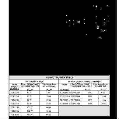
Top221-227 5rv70
January 2022 0
Cl 2n 26312r
April 2020 28
Bat 2n 3k2ig
November 2019 59More Documents from "Aaaaa" 2x4ia
2n Ip Automation Manual En 2.27 3w2y1d
March 2023 0
Opel Astra J Manual 434cl
January 2022 0
Contoh Surat Pernyataan Pengembalian Beasiswa 5hr25
October 2020 0