Ail Process Ball Valve 5o586a
This document was ed by and they confirmed that they have the permission to share it. If you are author or own the copyright of this book, please report to us by using this report form. Report 2z6p3t
Overview 5o1f4z
& View Ail Process Ball Valve as PDF for free.
More details 6z3438
- Words: 12,258
- Pages: 20
Kancheepuram plant
AIL BALL VALVES FLOATING BALL DESIGN Maraimalai Nagar plant
AUDCO INDIA LIMITED istrative Of fice
Mount-Poonamallee Road, Manapakkam, Post Bag 976, Chennai 600 089, INDIA. Tel : (044) 22492323. Fa x : (044) 22495055, 22494055. Website : w w w.ailvalves.com
REDUCED BORE FULL BORE
Manufacturing Plants
Mount-Poonamallee Road, Manapakkam, Chennai 600 089, INDIA. Enathur, Kancheepuram 631 552, INDIA. B8, MMDA Industrial Area, Maraimalai Nagar 603 209, INDIA.
BS 5351 Marketed by
BS 5159
LARSEN & TOUBRO LIMITED Valves Business Group Post Bag 5247, Chennai 600 002, INDIA. Tel : (044) 28462086, 28462090. Fax: (044) 28462145.
PB No. : C2022-1/09.05 (supersedes C2022-0) As we continuously endeavour to improve our products, the data given herein are subject to change without notice.
AUDCO INDIA LIMITED
Introduction
valve manufacturer, with a strong presence in India and overseas.
The AIL Ball Valve has established itself as the industr y standard for quality, integrity, reliability and long service. The valves are manufactured to the latest international designs, using advanced manufacturing techniques and stringent quality control checks. Content
AIL has three manufacturing facilities. The main plant is located in Manapakkam, Chennai. The t wo other plants are at MM Nagar, 40 kilometres south and at Kancheepuram, 70 kilometres west of the main plant. The plants are equipped with specialised production facilities with special purpose machines, automatic welding equipment, heat treatment furnaces and testing equipment for total control of all manufacturing operations. In-house metallurgical and NDE laboratories, and gauge calibration facilities with up-to-date equipment provide suppor t to
ensur e
the
qualit y
of
products
manufactured.
Introduction
Page No.
03 - 05
Manufacturing Program ................................................... Salient Features ............................................................... Materials of Construction .................................................
Reduced Bore Valves
06 - 09
Three-piece Valves .......................................................... 06 & 07 Single-piece/Two-piece Valves ........................................ 08 &09
Full Bore Valves
10 - 13
Three-piece Valves .......................................................... 10 & 11 Single-piece/Two-piece Valves ........................................ 12 &13
Special Purpose Valves
14 & 15
Steam Ser vice .................................................................. Cr yogenic Ser vice ........................................................... Multipor t Valves ................................................................ High Pressure Ser vice .................................................... High Temperature Ser vice ............................................... Trunnion Mounted Ball Valves ...........................................
AIL Pneumatic Actuators
14 14 14 15 15 15
16 & 17
Technical Information AIL manufactures a wide variety of industrial
03 04 05
18
Pressure-Temperature Graphs ......................................... Flow Coef ficients ..............................................................
18 18
International Clientele • • • • • • • • • • • • • • • • • • •
ADNOC ARCO BASF CHEVRONTEXACO CITGO CNOOC CSPC DAEGU PETROCHEM DSM ENGEN ENOC EQUILLON EXXONMOBIL FORMOSA PLASTICS GASCO KNPC KOC MOTIVA NOVACOR
• • • • • • • • • • • • • • • • • • • •
PDO PERTAMINA PDVSA PETROCANADA PETRONAS PNOC, PHILIPPINES QATAR PETROLEUM REPSOL SAPREF SASOL SAUDI ARAMCO SECCO SEPCO SHELL STAR SUNOCO SYNCRUDE TOTAL UNION CARBIDE UNOCAL
• • • • • • • • • • • • • • • • • • • •
ABB AMEC BECHTEL CHIYODA CMI CONTRINA FLUOR FOSTER WHEELER JACOBS JGC KELLOG, BROWN & ROOT KRUPP UHDE KVAERNER LINDE PARSONS PETROFAC SNAMPROGETTI SNC LAVALIN TECHNIP WUHAN BOILERS
Global recognition
AUDCO INDIA LIMITED (AIL) is a leading
valves with ISO 9001 cer tified Qualit y Management System in all three plants.
Ordering Information
19
International Clientele
19
Ordering Information Familiarity with our catalogue numbering is not necessary when specifying or ordering our valves. A full description of the valve provided by you is translated into a catalogue number as per the system shown below : Three-piece Valves SIZE (in mm)
SERIES
8
3XR 3FXR
Chennai plant
32 50 65
OPERATOR
ENDS
Ball / Stem
T Virgin PTFE
L Lever Operated
NPT
- Screwed NPT
R R-PTFE*
P Pneumatic
BSPT - Screwed BSPT
816 WCB/A105
SS316
813 WCB/A105
SS304
X PEEK
866 CF8M
SS316
833 CF8
SS304
P Special filled PTFE
SCT
3HXR 3CXR 3DT XR 3DLXR 3TT XR 3TLXR
817 WCB/A105
Monel
A Acetal Resin
FL300- Flanged CL300
867 CF8M
Monel SS316L
8RR CF3
SS304L
C Seats for Cr yogenic Ser vice
FL600- Flanged CL600
8LL CF3M
20 25
Body & Connector
SEAT
3XF 3FXF
10 15
BODY & TRIM COMBINATIONS
Actuated
BSPL - Screwed BSPL - Socket weld
FL150- Flanged CL150
Single-piece / Two-piece Valves SIZE (in mm) 15 20
XR1 XR3
25
XF1 XF3
40 50 80 100 150 200
02
250
BODY & TRIM COMBINATIONS
SERIES
16 13 66 33 17 67 LL RR AA
Body & Connector
Ball / Stem
WCB/A105 WCB/A105 CF8M CF8 WCB/A105 CF8M CF3M CF3 Alloy 20
SS316 SS304 SS316 SS304 Monel Monel SS316L SS304L Alloy 20
SEAT
OPERATOR
T Virgin PTFE
L Lever Operated
R R-PTFE*
W Wrench
X PEEK
G Gear Unit
P Special filled PTFE
P Pneumatic Actuated E Electrically Actuated
NOTE * R-PTFE : 15% Glassfilled (reinforced) PTFE For any other special requirement, add SPL to the catalogue number and provide details. Special options such as ex tension spindles, ex tension nipples and locking arrangements are also available.
19
Technical Information
Quality Policy
Q
Audco India Limited is committed to Total Customer Satisfaction. We achieve this by : • Maintaining a high standard of quality consistent with the customer requirements • Complying with the Codes, Standards, Customer Specifications, Statutory and Regulatory requirements as applicable to our Products • Continually improving the effectiveness of Quality Management System to add value to our Products
The floating ball design of Ball Valves is the universal choice for most process and utility applications. In this design, sealing takes place by allowing the ball under pressure to move towards the downstream seat to ef fect a tight seal. Other designs, such as the Trunnion Mounted design, are also maunfactured by AIL, details of which are available in a separate catalogue. THREE-PIECE DESIGN
SINGLE-PIECE / TWO-PIECE DESIGN
Ball Valves featuring this design are the most easily on-line maintainable in their class. By removing thre e body connector bolts and loosening the four th, the body can be swung away using the fourth bolt as the fulcrum, to carry out any installation or maintenance operation on the valve. This feature reduces maintenance downtime to a bare minimum.
Single-piece ball valves are high per formance valves, which come with a one-piece integrally flanged body, in sizes of up to 200mm reduced bore and 40mm full bore. This design of fers the unique advantage of eliminating the possibility of ex ternal leakage to the atmosphere through bolted body ts. These environment-friendly and high-integrity valves are preferred in critical applications where the media is expensive, volatile or toxic, and where ex ternal leakage or wastage is unacceptable. The t wo-piece design complements the single-piece design in sizes of 250mm and above reduced bore, and 50mm and above full bore.
Manufacturing Program Valve Type
REDUCED BORE
Standard
Flow Coef ficients (Kv values) 15
20
25
32
40
50
65
80
100
150
200
250
Reduced bore
7
10
28
39
71
104
208
303
623
882
1557
2569
Full bore
33
61
95
199
303
433
675
1002
1832
4366
8077
16003
Kv = flow coef ficient in m3/hr
BS 5159
3-piece
singlepiece
Fire-safe
BS 5351
BS 5351
8
10 15 20 25 32 40 50 80 100 150 200 250
Screwed/SW
G
G
Flanged 150/ 300/600
SPECIAL PURPOSE VALVES
Flanged 150/ 300/600 Flanged 150 Flanged 300
G
G
G
G
G
G
G
G
G
G
G
G
G
G
G
G
G
G
G
G
G
G
G
G
G
G
G
G
G
G
G
G
G
G
Standard
BS 5159
Fire-safe
BS 5351
3-piece
singlepiece
Valve Size
End Connection
Screwed/SW Fire-safe
2-piece
Valve Size
Compliance
2-piece
FULL BORE
The information contained in this section is to be used only as a guide to the ma ximum temperaturepressure combination that the seat material can withstand. Other factors such as process medium, material of construction of metal parts and design rating of the valve can also restrict overall valve per formance.
18
Introduction
Pressure-Temperature Graphs
Fire-safe
BS 5351
Screwed SW Flanged 150 Flanged 300 Flanged 600 Flanged 150 Flanged 300
Valves for Steam Service Valves for Cr yogenic Service Multipor t Ball Valves Valves for High Pressure Service Valves for High Temperature Ser vice Trunnion Mounted Ball Valves
G
G
G
G
G
G
G
G
G
G
G
G
G
G
G
G
G
Refer pages 14 & 15
03
Introduction
A number of outstanding features in AIL Ball Valves of fer significant advantages to the . FIRE-SAFE FEATURE ANTISTATIC FEATURE Build-up of static electricit y can occur as a result of constant rubbing of the ball against the PTFE seats. This can be a potential fire hazard, especially while handling inflammable fluids. To provide electrical continuit y, spring-loaded plungers are provided bet ween the stem and the ball in single-piece and t wo-piece reduced bore (80mm and above) and full bore (40mm and above) valves. For smaller sizes, this is achieved through 35% Carbon-filled PTFE stem seals. Depending on the choice of seals, the designs also provide for additional spring-loaded plungers bet ween the stem and the body for full mechanical antistatic capability.
MOULDED PTFE SEATS WITH SLOTS PTFE seats are manufactured from moulded PTFE for a bet ter grain structure compared to other methods of manufacture. Slots are provided in the seats to relieve the pressure past the upstream seat and prevent it from being forced against the ball. These features help lower operating torques, permit higher dif ferential pressures and reduce wear, besides ex tending service life.
As a standard, AIL Ball Valves are supplied with hand levers or gear units, depending on the valve size. The valves are also suitable for automation using either electric or pneumatic actuators. The AIL Series 90 Pneumatic Actuator is optimally designed for use with AIL Ball Valves, and is widely used to automate valves in diverse applications. Refer to page 17 for actuator selection data.
AIL Ball Valves are available with a wide variet y of seat and seal material combinations to suit specific needs of customers. For details, refer to tables on page 5.
CAVITY PRESSURE RELIEF AIL’s range of two-piece full bore valves can be of fered with built-in cavit y relief seat design on request. This feature prevents overpressure in the ball cavit y due to thermal expansion of the line fluid, and finds use in applications involving volatile line fluids. In principle, when cavit y pressure builds up and reaches a cer tain magnitude, it causes the seat lip to move away from the ball relieving the pressure. Once the pressure has relieved, the seat lip returns until the pressure builds up again. In the case of single-piece and three-piece valves, and in t wo-piece reduced bore valves, cavity relief can be provided on request by incorporating an upstream relief hole in the ball. All valves have a hole connecting the ball por t and the body cavit y to prevent build-up of trapped cavit y pressure when the valve is in open position.
LEAK TIGHT STEM SEALING
stem shoulder
stem seal
The stem seal package consists of one or t wo stem seals and one or a series of gland packing rings, depending on valve size. In smaller sizes of up to 50mm, a pair of Belleville washers acts as a spring to compensate for wear and thermal expansion.
DOUBLE ACTING R ANGE
SPRING RETURN R ANGE
Reduced Bore Valves 5.6kg/cm2 (80psi)
Reduced Bore Valves 5.6kg/cm2 (80psi)
Full Bore Valves 5.6kg/cm2 (80psi) Full Bore Valves 5.6kg/cm2 (80psi)
WIDE VARIET Y OF SEATS AND BODY SEALS
The stainless steel balls are manufactured to ver y close sphericit y tolerances and are mirror-finished. This results in bubble-tight sealing and considerably reduced operating torque.
All AIL Ball Valves have a bot tom-entry stem design which features stem inser tion from inside the body. An integral shoulder on the stem sits against the shoulder in the body, giving it blow-out proof integrit y. The higher the line pressure, the tighter the seal. This design of fers safet y body gland features superior to topshoulder packing entr y stem design where the line pressure works to break the stem seating (see illustration for typical threepiece design).
Use the char ts below to select the appropriate model of actuator. The valve size (X-a xis), the valve operating pressure (Y-a xis) and the actuator air supply pressure (80psi or 60psi indicated in the chart title) together determine the actuator selection. For selection of actuators for TMBV, please AIL.
VALVE OPERATION
MIRROR-FINISHED SS BALLS
BLOW-OUT PROOF STEM
04
AIL fire-safe design valves feature a secondar y metalto-metal seat which renders the valve fire-safe. An integral metal lip in the body and the configuration of the sof t seat are designed to prevent the sof tening downstream seat from being forced into the port in the event of a fire. When the seat is totally sublimated in a fire, the ball moves and rests against the lip, forming a metal-to-metal seat, thus ensuring leak-tightness. End connectors or inser ts have spigoted ends to ensur e concentricit y and correct alignment of the ball.
Guide
Reduced Bore Valves 4.2kg/cm2 (60psi)
AIL Pneumatic Actuators
Selection
Reduced Bore Valves 4.2kg/cm2 (60psi)
Full Bore Valves 4.2kg/cm2 (60psi)
Full Bore Valves 4.2kg/cm2 (60psi)
ACTUATOR MOUNTING FLANGE All single-piece and t wo-piece valves are supplied with an integral actuator mounting flange with drilled and tapped holes suitable for mounting pneumatic actuators. The flange conforms to ISO 5211 for full bore valves and to AIL’s manufacturing standard for reduced bore valves.
05DA
20DA
50DA
90DA
10DA
30DA
70DA
100DA
110DA
05SR50
20SR60
30SR80
70SR70
100SR70
05SR60
20SR70
50SR60
70SR80
100SR80
05SR80
20SR80
50SR70
90SR60
110SR60
10SR50
30SR50
50SR80
90SR70
110SR80
10SR80
30SR60
70SR50
90SR80
120SR70
20SR50
30SR70
70SR60
100SR60
120SR80
17
AIL Pneumatic Actuators
Series 90 Double Acting and Spring Return types BODY AND BODY CONNECTOR AIL Pneumatic Actuators are among the widely used actuators today and are in service in diverse industries such as pharmaceutical, chemical, petrochemical, food and nuclear power. Compactness, reliability, low maintenance needs and ruggedness combine to make these actuators the best choice for use with ball valves. Spring Return (SR) type Actuator
Material
Specification
Carbon Steel Carbon Steel Stainless Steel Stainless Steel Stainless Steel Stainless Steel Alloy 20 LCB
ASTM ASTM ASTM ASTM ASTM ASTM ASTM ASTM
Gr. Gr. Gr. Gr. Gr. Gr. Gr.
WCB CF8M CF8 CF3M CF3 CN7M LCB
Details of cer tain common materials of construction are furnished here. For a more exhaustive list of available materials and for guidance on body/ball/seat material combinations, refer to Ordering Information on page 19. NOTE : Materials conforming to NACE standard, and for special ser vices like Ox ygen and Hydrogen can be supplied.
Double Acting (DA) type Actuator TRIMS (CONSISTING OF BALL / STEM) SERIES 90 ACTUATOR The AIL Series 90 Actuator is optimised for use with AIL ball valves for safe remote plant automation. Of fered in two options - Double Acting (DA) and Spring Return (SR) - this actuator incorporates a rack-and-pinnion mechanism to ensure positive engagement and a constant torque output throughout the entire cycle.
Material Specifications
Material
Specification (Ball / Stem)
Stainless Steel Stainless Steel Stainless Steel Stainless Steel 13% Cr. Steel Monel Hastelloy C Alloy 20
ASTM ASTM ASTM ASTM ASTM ASTM ASTM ASTM
A351 Gr. CF8M / AISI 316 A351 Gr. CF8 / AISI 304 A351 Gr. CF3M / AISI 316L A351 Gr. CF3 / AISI 304L A351 Gr. CA15 / AISI 410 A494 Gr. M35-1 / ASTM B164 Gr. N04400 A494 Gr. CW-12MW / ASTM B574 Gr. N10276 A351 Gr. CN7M
Features
Description
Material
Housing / Piston and End Cap
Aluminium Alloy
Pinnion
Steel
Seals
Nitrile Elastomer
Retention Spring Wire
Stainless Steel
Pinnion Bush
Nylon or filled PTFE
Springs
Spring Steel
Housing : Precision-ex truded or cast, to of fer a light weight, compact body with sound pressure por ting. Anodised to provide resistance to wear and corrosion. Piston : Rugged one-piece piston with integral rack to ensure positive engagement with the pinnion. Anodised to provide resistance to wear and corrosion. Pinnion : Surface-tested with low-friction coating for smooth operation. End Cover : Powder-coated for resistance to corrosion, with a single SS spring wire for positive clamping. Pinnion Bush : Self-lubricated for low friction and smooth operation.
SEATS Material
Description
PTFE
The most common seating material, suitable for almost all media, as it possesses excellent corrosion resistance Stronger than PTFE seats and has higher temperature/pressure ratings Carbon, Glass and Graphite-filled PTFE - suited for steam and thermal resistance and has good abrasion resistance. Good for high-cycle applications PEEK (Poly Ether Ether Ketone) is a material that demonstrates outstanding pressure capabilities at elevated temperatures - has excellent chemical and abrasion resistance Made of SS 316 and impregnated with Graphite for sizes of up to 50mm and hard-faced with Stellite for larger sizes Capable of handling ex tremely high pressures - not suited for Oxygen service
15% Glass-filled (reinforced) PTFE Special-filled PTFE PEEK
Technical Specifications Mounting standard
Ordering Information ISO 5211
Pinnion top
NAMUR
Media
Filtered and lubricated dry air or inert gas
Temperature range
-100C to +800C
Operating pressure range
Double Acting 2.1kg/cm2 to 8.4kg/cm2 (30psi to 120psi) Spring Return 2.1kg/cm2 to 7.0kg/cm2 (30psi to 100psi)
Rotation
16
A105 A216 A351 A351 A351 A351 A351 A352
AIL Ball Valves can be supplied in a highly versatile range of body, seat and trim combinations to suit almost all types of services.
Introduction
Pneumatic Actuators
Open - counterclockwise Close - clockwise
Model number : Use the Actuator Selection Guide to select the required actuator model. Ser vice conditions : Line fluid, temperature, dif ferential pressure and frequency of operation. Actuator data : Double Acting or Spring Return ; operating media, operating pressure, media temperature (ma x) and operating time required. Solenoid Valve : Type, size, material, power supply ; enclosure (weather-pro of / flame-pro of) with relevant standards. Limit Switch : Nos., Switch t ype (1NO+1NC or 2NO+2NC), power supply (DC/AC), electrical rating (VA or wat ts), enclosure (weather-proof / flameproof) with relevant standards. Other accessories : Manual override, quick exhaust valve, accummulator, air filter regulator etc.
Metal Acetal Resin
BODY SEALS Material
Description
PTFE
The most common body seal material, suitable for almost all media, as it possesses excellent corrosion resistance Stronger than PTFE seats and has higher temperature/pressure ratings PEEK (Poly Ether Ether Ketone) is a material that demonstrates outstanding pressure capabilities at elevated temperatures - has excellent chemical and abrasion resistance Used in fire-safe valves and in steam applications
15% Glass-filled (reinforced) PTFE PEEK Graphite
05
AIL Series 3XR/3FXR
VALVES FOR HIGH PRESSURE SERVICE 3HXR
Three-piece design 3XR - Standard series
3FXR - Fire-safe series
This 3-piece Ball Valve is the most easily on-line maintainable in its class. By removing three body connector bolts and loosening the fourth, the body can be swung away using the four th bolt as the fulcrum, to carry out any installation or maintenance operation on the valve, thus reducing downtime. This valve can be of fered in a wide variet y of body and seat combinations.
This 3-piece fire-safe design Ball Valve features a secondary metal seat which renders the valve firesafe. When the seat is totally sublimated in a fire, the ball moves and rests against the lip, forming a metalto-metal seat, thus ensuring leak-tightness.
The AIL Series 3HXR Ball Valve has been specially developed to meet the industry’s requirement of a safe and reliable shutof f valve for high-pressure applications. This valve incorporates a number of product features like high-pressure seals, thicker flanges on the body connectors, high-tensile bolting, special acetal resin seats, high-strength stem and highpressure integrity gland assembly.
Material Specification
3HXR
Par t
Carbon Steel version only
Body
ASTM A105/A216 Gr. WCB
Body Connector
ASTM A105/A216 Gr. WCB / IS 1875 Cl 2
Ball
ASTM A351 Gr. CF8M
Seat
Acetal Resin
Stem
ASTM A564 Type 630
Body Seal
Nitrile Rubber
Gland Packing
15% glass-filled PTFE
Stem Seal
Nylon
Specifications Ma x. cold 352kg/cm2 for liquids working pressure 210kg/cm2 for gases (15-25mm) 168kg/cm2 for gases (40-50mm)
Dimensional Details Screwed/Socket-weld end (in mm, unless specified) Valve Size
A
8
65
C
122
D
E
14.6 / 14.2
45
F
G
9.7
1
/4”
0.6
/8”
0.6
Valve Size
25
108 131 149 256 34.3 / 33.8
60
76
12.7
40
131 142 256 256 49.2 / 48.7
76
81
12.7
50
142 142 256 256 61.7 / 61.1
81
81
16.0
Test pressures Ends Shell (hydrostatic) Seat
(air)
kg/cm2 (psi) 527.0 (7500) 5.6
(80)
45
9.7
1
/2”
0.6
VALVES FOR HIGH TEMPER ATURE SERVICE
3
/4”
0.8
1”
1.6
These are high-durability ball valves for superheated steam and high temperature applications, with the following features : • Ability to handle high presuure and temperature shock • Ability to withstand high pressure drops • Ability to resist abrasion and wear • Services up to 3400C and 100kg/cm2 pressure
107 149
43.1 / 42.7
65 12.7 11/4 ”
2.5
40
116 181
49.2 / 48.7
75 12.7 11/2 ”
3.3
50
128 181
61.7 / 61.1
80 15.9
4.1
2”
77.8 85
The standard 3HXR valve is a reduced bore valve.
22.2 / 21.8
32
9.7 12.7
122
59 12.7
50 60
67
34.3 / 33.8
47 50
15
149
122 122 22.2 / 21.8
108 122 149 27.6 / 27.1
9.7
95
F
S/W end
85
45
25
E Scr. end
20
18.0 / 17.6
48 12.7
D
AIL Standard
122
27.6 / 27.1
S/W end
15
65
122
Scr. end
Face-to-face dimensions
10
73
C S/W end
BS 5159 API 598
3
20
A Scr. end
Valve design Testing
Pressure Testing
Approx. Weight (kg)
Dimensional Details (in mm, unless specified)
NOTE : Available in single-piece and three-piece designs. For general dimensions, refer to earlier tables.
AIL Special-purpose Ball Valves
Reduced Bore Ball Valves
The metal-seated versions have a graphite impregnated alloy stainless steel seat with integral graphite seat seal. These are suitable for conditions up to 3400C and 70kg/cm2. The stainless steel ball is ENP coated to make the surface harder. The resilient seated versions feature PEEK seats which handle conditions up to 2800C and 100kg/cm2.
Dimensional Details - Flanged end (in mm, unless specified) Valve Size
06
C
D
E
Class 150 A
F
Class 300 G
A
Approx. Weight (kg)
Class 600
F
G
A
F
G
Cl. 150 Cl. 300
Cl. 600
15
152 12.7 90
108
89 11.1 140
96
15
165
96
22
1.8
2.2
4.5
20
152 19.1 98
117
99 12.2 153 118
17
191 118
24
2.3
3.2
6.3
25
177 25.4 102 127 108 11.1 165 124
19
216 124
26
3.1
4.5
9.1
40
202 38.1 121 165 127 14.3 191 156
22
241 156
30
6.4
8.7
15.4
50
202 50.8 126 178 154 15.9 216 165
23
292 165
33
9.0
10.8
21.6
TRUNNION MOUNTED BALL VALVES The AIL Trunnion Mounted Ball Valve is the preferred choice of ball valve in higher sizes and pressure ratings, and is used in pipelines and critical process applications. In this design, sealing takes place by allowing the seat to move towards the ball along the flow a xis, which leads to lower operating torques over other types of valves. The valves have advanced design features such as a built-in cavit y relief mechanism, compact internal trunnion holder, and intrinsic double block and bleed facility. The valves are of two-piece design, bolted/welded at the body connection t, with flanged/butt weld ends, in reduced and full bore designs and in ratings of ASME Class 150 - 2500. For details, refer to the Trunnion Mounted Ball Valve Catalogue.
15
AIL Special-purpose Ball Valves
AIL Series 3XR/3FXR
Special-purpose Ball Valves VALVES FOR STEAM SERVICE These three-piece ball valves, fit ted with special filled PTFE seats, are specially designed for on/of f steam applications.
Material Specification Par t
Carbon Steel version only
Body & Body Connector
ASTM A105 or ASTMA216Gr.WCB
Ball
ASTM A351 Gr. CF8M
Seat
Special filled PTFE
Stem
AISI 316
Body Seal
Graphite
Gland Packing
35% Carbon-filled PTFE
Stem Seal
35% Carbon-filled PTFE
Pressure Testing
Specifications Ma x. cold working pressure
103kg/cm2 for scr. / sw end valves As per flange rating for flanged valves
Valve design Testing
BS 5159 API 598
Face-to-face dimensions
AIL Standard
Test pressures Ends Shell (hydrostatic) Seat
(air)
kg/cm2 (psi) 156.5 (2275) 5.6
(80)
The full range of reduced and full-bore valves are available with special designs for steam services. In general, these valves will have seats of special filled PTFE and body seals of graphite. Pressure ratings will be as per flange ratings in flanged valves and 103kg/cm2 for screwed/socket-weld end valves.
MULTIPORT BALL VALVES 3DTXR - T-Port Diverter Valve 3DLXR - L-Port Diverter Valve 3TT XR - T-Port Three-way Valve 3TLXR - L-Port Three-way Valve The Diver ter Valve is designed to divert media from the bottom inlet port to either of the t wo outlet ports. The Three-way Valve, also known as a Mixer Valve, permits use of any port as inlet. NOTE : Available in screwed and socket-weld designs. For material specifications and general dimensions, refer to table on 3XR series.
VALVES FOR CRYOGENIC SERVICE
Material Specification Sl. No.
Par t
3XR Carbon Steel
3FXR Stainless Steel
Carbon Steel
Stainless Steel
ASTM A105
ASTM A351 Gr. CF8M
1 2
Body ASTM A105 or ASTM A351 Gr. CF8M Body Connector ASTM A216 Gr. WCB
3
Ball
4
Seat
PTFE
PTFE
5
Stem
AISI 316
AISI 316
6
Body Seal
PTFE
Graphite
7
Gland Packing
35% Carbon-filled PTFE
Graphite
8
Stem Seal
35% Carbon-filled PTFE
35% Carbon-filled PTFE
ASTM A351 Gr. CF 8M
ASTM A351 Gr. CF 8M
3CXR The 3CXR series Cryogenic Valve is designed for low temperature services down to -1960C. Typical applications are LNG storage/distribution, terminal unloading stations, liquid Nitrogen and liquid Oxygen lines.The valves incorporate exclusive features such as : • Positive ball cavity relief - an upstream relief hole in the ball to prevent over pressure due to thermal expansion • Effective stem ex tensions - conformance to standard international practices ; selection of wall thickness and lengths to keep heat transfer down, packing frost-free, operational torques low and actuators well ed • Superior stem design - a one-piece stem with special stem seals to ensure a zero-leak stem and low operating torque • High performance sealing - special seats and body seals to ensure bubbletight shutof f and zero body leakage • Ease of installation - three-piece construction to facilitate easy installation and maintenance • Flexibility - a variety of end connections such as screwed end, socket-weld end and ex tension nipples
14
NOTE : For general dimensions, refer to table on 3XR series. AIL’s single-piece valves are also available for cryogenic service with and without stem ex tensions.
Specifications
Pressure Testing
Ma x. cold working pressure 69kg/cm2 for screwed/socketweld end valves with PTFE seat 103kg/cm2 for screwed/socketweld end valves with specialfilled PTFE seat As per flange rating for flanged valves
Test pressures Ends kg/cm2 (psi) Shell Screwed/Socket weld (air) 5.6 (80) Flanged 150 (hydrostatic) 31.5 (450) Flanged 300 (hydrostatic) 79.0 (1125) Flanged 600 (hydrostatic) 154.0 (2225)
Valve design
BS 5159 for 3XR Series BS 5351 for 3FXR Series
Fire Test (for 3FXR)
API 607 4th edition
Testing
API 598 for flanged valves
Face-to-face dimensions
ASME B16.10 for flanged valves and AIL Standard for screwed/socket-weld end valves
Seat
All valves (air)
5.6
(80)
NOTE
Pressure testing as per BS 6755 available on request. Shell hydrostatic test can be done for screwed and socket-weld end valves on request. Shell hydrostatic test can be done as per Class 800 rating for both versions on request.
07
AIL Series XR1/XR3
AIL Series XF1/XF3
Reduced Bore Ball Valves Single-piece and two-piece design XR - Fire-safe series These single-piece Ball Valves are high per formance valves which come with a one-piece integrally flanged body, in sizes of up to 200mm. This design of fers the unique advantage of eliminating the possibility of ex ternal leakage to the atmosphere through bolted body ts. These environment-friendly and high-integrity valves are preferred in critical applications where the media is expensive, volatile or toxic, and where ex ternal leakage or wastage is unacceptable.
The 2-piece design fire-safe design Ball Valves complement the single-piece design in 250mm size.
Dimensional Details - Flanged end (in mm, unless specified) Single-piece (Class 150)
Single-piece (Class 300) Approx. Weight (kg)
Valve Size
A
B
94
Valve Size
A
B
15
108
62
152 12.7 89
89 11.5
1.5
15
140
20
117
68
152 19.1 91
99 11.5
2.0
25
127
70
177 25.4 103 108 11.5
40
165
78
202 38.1 118 127 14.5
C
D
E
F
G
C
D
E
Approx. Weight (kg)
F
G
152 12.7 89
96
15
2.2
20
152 103 152 19.1 91
118
16
3.2
3.0
25
165 108 177 25.4 103 124
18
4.5
5.0
40
190 116 202 38.1 118 156
21
8.7
50
178 107 202 50.8 131 154 16.0
8.1
50
216 145 202 50.8 131 165 22.5
10.8
80
203 120 546 76.2 169 191 19.5
17.0
80
283 199 546 76.2 169 210
29
24.1
100
229 130 546 102.0 182 229 24.0
27.8
100
305 206 546 102.0 182 254
32
37.5
150
267 138 762 150.8 275 280 25.4
47.0
150
403 274 762 150.8 275 318
37
67.0
200
292 148
115.0
200
419 275
41
167.0
-
203.0
-
343 28.4
Two-piece (Class 150) Valve Size 250
A
B
C
D
E
F
G
H
330 165 148 254 686 406 30.5 578
Approx. Weight (kg)
210
-
203.0
-
381
Material Specification Sl. No.
Par t
Carbon Steel
Stainless Steel
1
Body
ASTM A216 Gr. WCB
ASTM A351 Gr. CF8M
2
Body Connector
ASTM A216 Gr. WCB
ASTM A351 Gr. CF8M
3
Ball
ASTM A351 Gr. CF 8M
ASTM A351 Gr. CF8M
4
Seat
PTFE
PTFE
5
Stem
AISI 316
AISI 316
6
Body Seal
Graphite
Graphite
7
Gland Packing
Graphite
Graphite
8
Stem Seal
25% Glass-filled PTFE
25% Glass-filled PTFE
9
Inser t
ASTM A105 / ASTM A216 Gr. WCB / IS1875 Cl2
AISI 316 or ASTM A351 Gr. CF8M
10
Insert gasket
Graphite
Graphite
XF Series - single-piece valves up to 40mm ; t wo-piece valves from 50mm onwards.
Specifications BS 5351
Fire test
API 607, 4th edition
Pressure testing
08
250
B
C
API 598 (testing as per ASME B16.10 (compliance to BS 2080 can
D
E
F
457 229 148 254 686 445
G
48
H
578
Approx. Weight (kg)
280
Test pressures Ends Shell Class 150 (hydrostatic) Class 300 (hydrostatic)
kg/cm2 (psi) 31.5 (450) 79.0 (1125)
BS 6755 Part I on request) Face-to-face dimensions
A
Pressure Testing
Valve design
Two-piece (Class 300) Valve Size
XF Series
Seat
Class 150 (air) Class 300 (air)
5.6 5.6
(80) (80)
be of fered on request) End flange dimensions
ASME B16.5 Class 150 RF and Class 300 RF
13
AIL Series XF1/XF3
AIL Series XR1/XR3
Full Bore Ball Valves Single-piece / Two-piece design XF Fire-safe Series (Class 150 & Class 300) These high performance full bore ball valves come in single-piece design (in sizes of 15 - 40mm) as well as in t wo-piece design (in sizes of 50 200mm). Advanced features such as fire safety, antistatic capability, cavity relief and blow-out proof stem are built into these valves. They are supplied with an integral actuator mounting flange with drilled and tapped holes conforming to ISO 5211.
50mm - 200mm
15mm - 40mm
Material Specification
Dimensional Details (in mm, unless specified) Class 150 Valve Size
A
B
15
108
46
D
E
H
163 12.7 97
-
1.8
Class 300 Valve Size
A
B
15
140
78
C
D
E
H
163 12.7 97
-
Approx. Weight (kg)
117
50
168 19.1 118
-
2.5
20
153
85
168 19.1 118
-
3.8
25
127
56
168 25.4 123
-
3.4
25
165
94
168 25.4 123
-
5.1
40
165
75
193 38.1 139
-
8.5
40
191 100 193 38.1 139
-
9.5
50
178
84
193 50.8 150
-
12.2
50
216
84
193 50.8 150
-
15.2
65
191
77
402 64.1 190
-
18.5
65
241
83
402 64.1 190
-
26.0
203
99
256 76.2 155
-
23.0
80
283
99
402 76.2 205
-
32.6
100
229 108 402 101.6 196
-
42.6
100
305 122 610 101.6 240
150
394 179 1004150.8 315
-
90.0
150
403 179
-
150.8 645 578
121.0
200
457 206
170.0
200
502 231
-
203.0 745 578
210.0
-
203.0 690 578
-
Sl. No.
Par t
1
Body
ASTM A216 Gr. WCB
ASTM A351 Gr. CF8M
2
Inser t
ASTM A105 or ASTM A216 Gr. WCB
AISI 316 or ASTM A351 Gr. CF8M
3
Ball
ASTM A351 Gr. CF 8M
ASTM A351 Gr. CF8M
4
Seat
PTFE
PTFE
5
Stem
AISI 316
AISI 316
6
Body Seal
PTFE
PTFE
7
Gland Packing
Graphite
Graphite
8
Stem Seal
35% Carbon-filled PTFE
35% Carbon-filled PTFE
9
Insert Seal
15mm - 40mm, 200mm : Metal-to-metal 50mm - 150mm : Graphite
15mm - 40mm, 200mm : Metal-to-metal 50mm - 150mm : Graphite
2.5
20
80
12
C
Approx. Weight (kg)
XR Series Carbon Steel
Pressure Testing
Specifications Valve design
BS 5351
Fire test
API 607, 4th edition
Pressure testing
Stainless Steel
API 598 (testing as per
Test pressures Ends Shell Class 150 (hydrostatic) Class 300 (hydrostatic)
kg/cm2 (psi) 31.5 (450) 79.0 (1125)
BS 6755 Part I on request)
59.0 Face-to-face dimensions
ASME B16.10
End flange dimensions
ASME B16.5 Class 150 RF and Class 300 RF
Seat
Class 150 (air) Class 300 (air)
5.6 5.6
(80) (80)
09
AIL Series 3XF/3FXF
AIL Series 3XF/3FXF
Full Bore Ball Valves Three-piece design 3XF - Standard series
3FXF - Fire-safe series
This 3-piece Ball Valve is the most easily on-line maintainable in its class. By removing three body connector bolts and loosening the fourth, the body can be swung away using the four th bolt as the fulcrum, to carry out any installation or maintenance operation on the valve, thus reducing downtime. This valve can be of fered in a wide variet y of body and seat combinations.
This 3-piece fire-safe design Ball Valve features a secondary metal seat which renders the valve firesafe. When the seat is totally sublimated in a fire, the ball moves and rests against the lip, forming a metalto-metal seat, thus ensuring leak-tightness.
Material Specification Sl. No.
Dimensional Details Screwed/Socket-weld end (in mm, unless specified) Valve Size
A
15
73
122
22.2 / 21.8
48
20
95
149
27.6 / 27.1
59 12.7
25
116 181
34.3 / 33.8
75 12.7
40
128 181
49.2 / 48.7
80 12.7 11/ 2 ”
C
D
E
F
G
9.7
Approx. Weight (kg)
1
/ 2”
0.8
3
/ 4”
1.6
1”
3.3
Par t
3XF Carbon Steel
3FXF Stainless Steel
15
10
E
3
Ball
4
Seat
PTFE
PTFE
5
Stem
AISI 316
AISI 316
6
Body Seal
PTFE
Graphite
7
Gland Packing
35% Carbon-filled PTFE
Graphite
8
Stem Seal
35% Carbon-filled PTFE
35% Carbon-filled PTFE
Max. cold working pressure
152 12.7 98
Class 150 A 108
F
Class 300 G
A
89 11.1 140
F 96
ASTM A351 Gr. CF8M
Body ASTM A105 or ASTM A351 Gr. CF8M Body Connector ASTM A216 Gr. WCB
Flanged end (in mm, unless specified) D
ASTM A105
1 2
ASTM A351 Gr. CF8M
Specifications
C
Stainless Steel
ASTM A351 Gr. CF8M
4.1
Dimensional Details
Valve Size
Carbon Steel
Approx. Weight (kg)
Class 600 G
15
A 165
F 96
G 22
Cl. 150 Cl. 300
2.3
3.2
Cl. 600
Valve design
BS 5159 for 3XF Series BS 5351 for 3FXF Series
Fire Test (for 3FXF)
API 607 4th edition
Testing
API 598 for flanged valves
Face-to-face dimensions
ASME B16.10 for flanged valves and AIL Standard for screwed/socket-weld end valves
6.3
20
177 19.1 102 117
99 12.2 153 118
17
191 118
24
3.1
4.5
9.1
25
202 25.4 121 127 108 11.1 165 124
19
216 124
26
6.4
8.7
15.4
40
202 38.1 126 165 127 14.3 191 156
22
241 156
30
9.0
10.8
21.6
Pressure Testing 69kg/cm2 for screwed/socket-weld end valves with PTFE seat 103kg/cm2 for screwed/socket-weld end valves with special-filled PTFE seat As per flange rating for flanged valves
Test pressures Ends Shell Scr./Socket weld (air) Flanged 150 (hydrostatic) Flanged 300 (hydrostatic) Flanged 600 (hydrostatic)
kg/cm2 (psi) 5.6 (80) 31.5 (450) 79.0 (1125) 154.0 (2225)
Seat
All valves (air)
5.6
(80)
NOTE
Pressure testing as per BS 6755 available on request. Shell hydrostatic test can be done for screwed and socket-weld end valves on request. Shell hydrostatic test can be done as per Class 800 rating for both versions on request.
11
AIL Series 3XF/3FXF
AIL Series 3XF/3FXF
Full Bore Ball Valves Three-piece design 3XF - Standard series
3FXF - Fire-safe series
This 3-piece Ball Valve is the most easily on-line maintainable in its class. By removing three body connector bolts and loosening the fourth, the body can be swung away using the four th bolt as the fulcrum, to carry out any installation or maintenance operation on the valve, thus reducing downtime. This valve can be of fered in a wide variet y of body and seat combinations.
This 3-piece fire-safe design Ball Valve features a secondary metal seat which renders the valve firesafe. When the seat is totally sublimated in a fire, the ball moves and rests against the lip, forming a metalto-metal seat, thus ensuring leak-tightness.
Material Specification Sl. No.
Dimensional Details Screwed/Socket-weld end (in mm, unless specified) Valve Size
A
15
73
122
22.2 / 21.8
48
20
95
149
27.6 / 27.1
59 12.7
25
116 181
34.3 / 33.8
75 12.7
40
128 181
49.2 / 48.7
80 12.7 11/ 2 ”
C
D
E
F
G
9.7
Approx. Weight (kg)
1
/ 2”
0.8
3
/ 4”
1.6
1”
3.3
Par t
3XF Carbon Steel
3FXF Stainless Steel
15
10
E
3
Ball
4
Seat
PTFE
PTFE
5
Stem
AISI 316
AISI 316
6
Body Seal
PTFE
Graphite
7
Gland Packing
35% Carbon-filled PTFE
Graphite
8
Stem Seal
35% Carbon-filled PTFE
35% Carbon-filled PTFE
Max. cold working pressure
152 12.7 98
Class 150 A 108
F
Class 300 G
A
89 11.1 140
F 96
ASTM A351 Gr. CF8M
Body ASTM A105 or ASTM A351 Gr. CF8M Body Connector ASTM A216 Gr. WCB
Flanged end (in mm, unless specified) D
ASTM A105
1 2
ASTM A351 Gr. CF8M
Specifications
C
Stainless Steel
ASTM A351 Gr. CF8M
4.1
Dimensional Details
Valve Size
Carbon Steel
Approx. Weight (kg)
Class 600 G
15
A 165
F 96
G 22
Cl. 150 Cl. 300
2.3
3.2
Cl. 600
Valve design
BS 5159 for 3XF Series BS 5351 for 3FXF Series
Fire Test (for 3FXF)
API 607 4th edition
Testing
API 598 for flanged valves
Face-to-face dimensions
ASME B16.10 for flanged valves and AIL Standard for screwed/socket-weld end valves
6.3
20
177 19.1 102 117
99 12.2 153 118
17
191 118
24
3.1
4.5
9.1
25
202 25.4 121 127 108 11.1 165 124
19
216 124
26
6.4
8.7
15.4
40
202 38.1 126 165 127 14.3 191 156
22
241 156
30
9.0
10.8
21.6
Pressure Testing 69kg/cm2 for screwed/socket-weld end valves with PTFE seat 103kg/cm2 for screwed/socket-weld end valves with special-filled PTFE seat As per flange rating for flanged valves
Test pressures Ends Shell Scr./Socket weld (air) Flanged 150 (hydrostatic) Flanged 300 (hydrostatic) Flanged 600 (hydrostatic)
kg/cm2 (psi) 5.6 (80) 31.5 (450) 79.0 (1125) 154.0 (2225)
Seat
All valves (air)
5.6
(80)
NOTE
Pressure testing as per BS 6755 available on request. Shell hydrostatic test can be done for screwed and socket-weld end valves on request. Shell hydrostatic test can be done as per Class 800 rating for both versions on request.
11
AIL Series XF1/XF3
AIL Series XR1/XR3
Full Bore Ball Valves Single-piece / Two-piece design XF Fire-safe Series (Class 150 & Class 300) These high performance full bore ball valves come in single-piece design (in sizes of 15 - 40mm) as well as in t wo-piece design (in sizes of 50 200mm). Advanced features such as fire safety, antistatic capability, cavity relief and blow-out proof stem are built into these valves. They are supplied with an integral actuator mounting flange with drilled and tapped holes conforming to ISO 5211.
50mm - 200mm
15mm - 40mm
Material Specification
Dimensional Details (in mm, unless specified) Class 150 Valve Size
A
B
15
108
46
D
E
H
163 12.7 97
-
1.8
Class 300 Valve Size
A
B
15
140
78
C
D
E
H
163 12.7 97
-
Approx. Weight (kg)
117
50
168 19.1 118
-
2.5
20
153
85
168 19.1 118
-
3.8
25
127
56
168 25.4 123
-
3.4
25
165
94
168 25.4 123
-
5.1
40
165
75
193 38.1 139
-
8.5
40
191 100 193 38.1 139
-
9.5
50
178
84
193 50.8 150
-
12.2
50
216
84
193 50.8 150
-
15.2
65
191
77
402 64.1 190
-
18.5
65
241
83
402 64.1 190
-
26.0
203
99
256 76.2 155
-
23.0
80
283
99
402 76.2 205
-
32.6
100
229 108 402 101.6 196
-
42.6
100
305 122 610 101.6 240
150
394 179 1004150.8 315
-
90.0
150
403 179
-
150.8 645 578
121.0
200
457 206
170.0
200
502 231
-
203.0 745 578
210.0
-
203.0 690 578
-
Sl. No.
Par t
1
Body
ASTM A216 Gr. WCB
ASTM A351 Gr. CF8M
2
Inser t
ASTM A105 or ASTM A216 Gr. WCB
AISI 316 or ASTM A351 Gr. CF8M
3
Ball
ASTM A351 Gr. CF 8M
ASTM A351 Gr. CF8M
4
Seat
PTFE
PTFE
5
Stem
AISI 316
AISI 316
6
Body Seal
PTFE
PTFE
7
Gland Packing
Graphite
Graphite
8
Stem Seal
35% Carbon-filled PTFE
35% Carbon-filled PTFE
9
Insert Seal
15mm - 40mm, 200mm : Metal-to-metal 50mm - 150mm : Graphite
15mm - 40mm, 200mm : Metal-to-metal 50mm - 150mm : Graphite
2.5
20
80
12
C
Approx. Weight (kg)
XR Series Carbon Steel
Pressure Testing
Specifications Valve design
BS 5351
Fire test
API 607, 4th edition
Pressure testing
Stainless Steel
API 598 (testing as per
Test pressures Ends Shell Class 150 (hydrostatic) Class 300 (hydrostatic)
kg/cm2 (psi) 31.5 (450) 79.0 (1125)
BS 6755 Part I on request)
59.0 Face-to-face dimensions
ASME B16.10
End flange dimensions
ASME B16.5 Class 150 RF and Class 300 RF
Seat
Class 150 (air) Class 300 (air)
5.6 5.6
(80) (80)
09
AIL Series XR1/XR3
AIL Series XF1/XF3
Reduced Bore Ball Valves Single-piece and two-piece design XR - Fire-safe series These single-piece Ball Valves are high per formance valves which come with a one-piece integrally flanged body, in sizes of up to 200mm. This design of fers the unique advantage of eliminating the possibility of ex ternal leakage to the atmosphere through bolted body ts. These environment-friendly and high-integrity valves are preferred in critical applications where the media is expensive, volatile or toxic, and where ex ternal leakage or wastage is unacceptable.
The 2-piece design fire-safe design Ball Valves complement the single-piece design in 250mm size.
Dimensional Details - Flanged end (in mm, unless specified) Single-piece (Class 150)
Single-piece (Class 300) Approx. Weight (kg)
Valve Size
A
B
94
Valve Size
A
B
15
108
62
152 12.7 89
89 11.5
1.5
15
140
20
117
68
152 19.1 91
99 11.5
2.0
25
127
70
177 25.4 103 108 11.5
40
165
78
202 38.1 118 127 14.5
C
D
E
F
G
C
D
E
Approx. Weight (kg)
F
G
152 12.7 89
96
15
2.2
20
152 103 152 19.1 91
118
16
3.2
3.0
25
165 108 177 25.4 103 124
18
4.5
5.0
40
190 116 202 38.1 118 156
21
8.7
50
178 107 202 50.8 131 154 16.0
8.1
50
216 145 202 50.8 131 165 22.5
10.8
80
203 120 546 76.2 169 191 19.5
17.0
80
283 199 546 76.2 169 210
29
24.1
100
229 130 546 102.0 182 229 24.0
27.8
100
305 206 546 102.0 182 254
32
37.5
150
267 138 762 150.8 275 280 25.4
47.0
150
403 274 762 150.8 275 318
37
67.0
200
292 148
115.0
200
419 275
41
167.0
-
203.0
-
343 28.4
Two-piece (Class 150) Valve Size 250
A
B
C
D
E
F
G
H
330 165 148 254 686 406 30.5 578
Approx. Weight (kg)
210
-
203.0
-
381
Material Specification Sl. No.
Par t
Carbon Steel
Stainless Steel
1
Body
ASTM A216 Gr. WCB
ASTM A351 Gr. CF8M
2
Body Connector
ASTM A216 Gr. WCB
ASTM A351 Gr. CF8M
3
Ball
ASTM A351 Gr. CF 8M
ASTM A351 Gr. CF8M
4
Seat
PTFE
PTFE
5
Stem
AISI 316
AISI 316
6
Body Seal
Graphite
Graphite
7
Gland Packing
Graphite
Graphite
8
Stem Seal
25% Glass-filled PTFE
25% Glass-filled PTFE
9
Inser t
ASTM A105 / ASTM A216 Gr. WCB / IS1875 Cl2
AISI 316 or ASTM A351 Gr. CF8M
10
Insert gasket
Graphite
Graphite
XF Series - single-piece valves up to 40mm ; t wo-piece valves from 50mm onwards.
Specifications BS 5351
Fire test
API 607, 4th edition
Pressure testing
08
250
B
C
API 598 (testing as per ASME B16.10 (compliance to BS 2080 can
D
E
F
457 229 148 254 686 445
G
48
H
578
Approx. Weight (kg)
280
Test pressures Ends Shell Class 150 (hydrostatic) Class 300 (hydrostatic)
kg/cm2 (psi) 31.5 (450) 79.0 (1125)
BS 6755 Part I on request) Face-to-face dimensions
A
Pressure Testing
Valve design
Two-piece (Class 300) Valve Size
XF Series
Seat
Class 150 (air) Class 300 (air)
5.6 5.6
(80) (80)
be of fered on request) End flange dimensions
ASME B16.5 Class 150 RF and Class 300 RF
13
AIL Special-purpose Ball Valves
AIL Series 3XR/3FXR
Special-purpose Ball Valves VALVES FOR STEAM SERVICE These three-piece ball valves, fit ted with special filled PTFE seats, are specially designed for on/of f steam applications.
Material Specification Par t
Carbon Steel version only
Body & Body Connector
ASTM A105 or ASTMA216Gr.WCB
Ball
ASTM A351 Gr. CF8M
Seat
Special filled PTFE
Stem
AISI 316
Body Seal
Graphite
Gland Packing
35% Carbon-filled PTFE
Stem Seal
35% Carbon-filled PTFE
Pressure Testing
Specifications Ma x. cold working pressure
103kg/cm2 for scr. / sw end valves As per flange rating for flanged valves
Valve design Testing
BS 5159 API 598
Face-to-face dimensions
AIL Standard
Test pressures Ends Shell (hydrostatic) Seat
(air)
kg/cm2 (psi) 156.5 (2275) 5.6
(80)
The full range of reduced and full-bore valves are available with special designs for steam services. In general, these valves will have seats of special filled PTFE and body seals of graphite. Pressure ratings will be as per flange ratings in flanged valves and 103kg/cm2 for screwed/socket-weld end valves.
MULTIPORT BALL VALVES 3DTXR - T-Port Diverter Valve 3DLXR - L-Port Diverter Valve 3TT XR - T-Port Three-way Valve 3TLXR - L-Port Three-way Valve The Diver ter Valve is designed to divert media from the bottom inlet port to either of the t wo outlet ports. The Three-way Valve, also known as a Mixer Valve, permits use of any port as inlet. NOTE : Available in screwed and socket-weld designs. For material specifications and general dimensions, refer to table on 3XR series.
VALVES FOR CRYOGENIC SERVICE
Material Specification Sl. No.
Par t
3XR Carbon Steel
3FXR Stainless Steel
Carbon Steel
Stainless Steel
ASTM A105
ASTM A351 Gr. CF8M
1 2
Body ASTM A105 or ASTM A351 Gr. CF8M Body Connector ASTM A216 Gr. WCB
3
Ball
4
Seat
PTFE
PTFE
5
Stem
AISI 316
AISI 316
6
Body Seal
PTFE
Graphite
7
Gland Packing
35% Carbon-filled PTFE
Graphite
8
Stem Seal
35% Carbon-filled PTFE
35% Carbon-filled PTFE
ASTM A351 Gr. CF 8M
ASTM A351 Gr. CF 8M
3CXR The 3CXR series Cryogenic Valve is designed for low temperature services down to -1960C. Typical applications are LNG storage/distribution, terminal unloading stations, liquid Nitrogen and liquid Oxygen lines.The valves incorporate exclusive features such as : • Positive ball cavity relief - an upstream relief hole in the ball to prevent over pressure due to thermal expansion • Effective stem ex tensions - conformance to standard international practices ; selection of wall thickness and lengths to keep heat transfer down, packing frost-free, operational torques low and actuators well ed • Superior stem design - a one-piece stem with special stem seals to ensure a zero-leak stem and low operating torque • High performance sealing - special seats and body seals to ensure bubbletight shutof f and zero body leakage • Ease of installation - three-piece construction to facilitate easy installation and maintenance • Flexibility - a variety of end connections such as screwed end, socket-weld end and ex tension nipples
14
NOTE : For general dimensions, refer to table on 3XR series. AIL’s single-piece valves are also available for cryogenic service with and without stem ex tensions.
Specifications
Pressure Testing
Ma x. cold working pressure 69kg/cm2 for screwed/socketweld end valves with PTFE seat 103kg/cm2 for screwed/socketweld end valves with specialfilled PTFE seat As per flange rating for flanged valves
Test pressures Ends kg/cm2 (psi) Shell Screwed/Socket weld (air) 5.6 (80) Flanged 150 (hydrostatic) 31.5 (450) Flanged 300 (hydrostatic) 79.0 (1125) Flanged 600 (hydrostatic) 154.0 (2225)
Valve design
BS 5159 for 3XR Series BS 5351 for 3FXR Series
Fire Test (for 3FXR)
API 607 4th edition
Testing
API 598 for flanged valves
Face-to-face dimensions
ASME B16.10 for flanged valves and AIL Standard for screwed/socket-weld end valves
Seat
All valves (air)
5.6
(80)
NOTE
Pressure testing as per BS 6755 available on request. Shell hydrostatic test can be done for screwed and socket-weld end valves on request. Shell hydrostatic test can be done as per Class 800 rating for both versions on request.
07
AIL Series 3XR/3FXR
VALVES FOR HIGH PRESSURE SERVICE 3HXR
Three-piece design 3XR - Standard series
3FXR - Fire-safe series
This 3-piece Ball Valve is the most easily on-line maintainable in its class. By removing three body connector bolts and loosening the fourth, the body can be swung away using the four th bolt as the fulcrum, to carry out any installation or maintenance operation on the valve, thus reducing downtime. This valve can be of fered in a wide variet y of body and seat combinations.
This 3-piece fire-safe design Ball Valve features a secondary metal seat which renders the valve firesafe. When the seat is totally sublimated in a fire, the ball moves and rests against the lip, forming a metalto-metal seat, thus ensuring leak-tightness.
The AIL Series 3HXR Ball Valve has been specially developed to meet the industry’s requirement of a safe and reliable shutof f valve for high-pressure applications. This valve incorporates a number of product features like high-pressure seals, thicker flanges on the body connectors, high-tensile bolting, special acetal resin seats, high-strength stem and highpressure integrity gland assembly.
Material Specification
3HXR
Par t
Carbon Steel version only
Body
ASTM A105/A216 Gr. WCB
Body Connector
ASTM A105/A216 Gr. WCB / IS 1875 Cl 2
Ball
ASTM A351 Gr. CF8M
Seat
Acetal Resin
Stem
ASTM A564 Type 630
Body Seal
Nitrile Rubber
Gland Packing
15% glass-filled PTFE
Stem Seal
Nylon
Specifications Ma x. cold 352kg/cm2 for liquids working pressure 210kg/cm2 for gases (15-25mm) 168kg/cm2 for gases (40-50mm)
Dimensional Details Screwed/Socket-weld end (in mm, unless specified) Valve Size
A
8
65
C
122
D
E
14.6 / 14.2
45
F
G
9.7
1
/4”
0.6
/8”
0.6
Valve Size
25
108 131 149 256 34.3 / 33.8
60
76
12.7
40
131 142 256 256 49.2 / 48.7
76
81
12.7
50
142 142 256 256 61.7 / 61.1
81
81
16.0
Test pressures Ends Shell (hydrostatic) Seat
(air)
kg/cm2 (psi) 527.0 (7500) 5.6
(80)
45
9.7
1
/2”
0.6
VALVES FOR HIGH TEMPER ATURE SERVICE
3
/4”
0.8
1”
1.6
These are high-durability ball valves for superheated steam and high temperature applications, with the following features : • Ability to handle high presuure and temperature shock • Ability to withstand high pressure drops • Ability to resist abrasion and wear • Services up to 3400C and 100kg/cm2 pressure
107 149
43.1 / 42.7
65 12.7 11/4 ”
2.5
40
116 181
49.2 / 48.7
75 12.7 11/2 ”
3.3
50
128 181
61.7 / 61.1
80 15.9
4.1
2”
77.8 85
The standard 3HXR valve is a reduced bore valve.
22.2 / 21.8
32
9.7 12.7
122
59 12.7
50 60
67
34.3 / 33.8
47 50
15
149
122 122 22.2 / 21.8
108 122 149 27.6 / 27.1
9.7
95
F
S/W end
85
45
25
E Scr. end
20
18.0 / 17.6
48 12.7
D
AIL Standard
122
27.6 / 27.1
S/W end
15
65
122
Scr. end
Face-to-face dimensions
10
73
C S/W end
BS 5159 API 598
3
20
A Scr. end
Valve design Testing
Pressure Testing
Approx. Weight (kg)
Dimensional Details (in mm, unless specified)
NOTE : Available in single-piece and three-piece designs. For general dimensions, refer to earlier tables.
AIL Special-purpose Ball Valves
Reduced Bore Ball Valves
The metal-seated versions have a graphite impregnated alloy stainless steel seat with integral graphite seat seal. These are suitable for conditions up to 3400C and 70kg/cm2. The stainless steel ball is ENP coated to make the surface harder. The resilient seated versions feature PEEK seats which handle conditions up to 2800C and 100kg/cm2.
Dimensional Details - Flanged end (in mm, unless specified) Valve Size
06
C
D
E
Class 150 A
F
Class 300 G
A
Approx. Weight (kg)
Class 600
F
G
A
F
G
Cl. 150 Cl. 300
Cl. 600
15
152 12.7 90
108
89 11.1 140
96
15
165
96
22
1.8
2.2
4.5
20
152 19.1 98
117
99 12.2 153 118
17
191 118
24
2.3
3.2
6.3
25
177 25.4 102 127 108 11.1 165 124
19
216 124
26
3.1
4.5
9.1
40
202 38.1 121 165 127 14.3 191 156
22
241 156
30
6.4
8.7
15.4
50
202 50.8 126 178 154 15.9 216 165
23
292 165
33
9.0
10.8
21.6
TRUNNION MOUNTED BALL VALVES The AIL Trunnion Mounted Ball Valve is the preferred choice of ball valve in higher sizes and pressure ratings, and is used in pipelines and critical process applications. In this design, sealing takes place by allowing the seat to move towards the ball along the flow a xis, which leads to lower operating torques over other types of valves. The valves have advanced design features such as a built-in cavit y relief mechanism, compact internal trunnion holder, and intrinsic double block and bleed facility. The valves are of two-piece design, bolted/welded at the body connection t, with flanged/butt weld ends, in reduced and full bore designs and in ratings of ASME Class 150 - 2500. For details, refer to the Trunnion Mounted Ball Valve Catalogue.
15
AIL Pneumatic Actuators
Series 90 Double Acting and Spring Return types BODY AND BODY CONNECTOR AIL Pneumatic Actuators are among the widely used actuators today and are in service in diverse industries such as pharmaceutical, chemical, petrochemical, food and nuclear power. Compactness, reliability, low maintenance needs and ruggedness combine to make these actuators the best choice for use with ball valves. Spring Return (SR) type Actuator
Material
Specification
Carbon Steel Carbon Steel Stainless Steel Stainless Steel Stainless Steel Stainless Steel Alloy 20 LCB
ASTM ASTM ASTM ASTM ASTM ASTM ASTM ASTM
Gr. Gr. Gr. Gr. Gr. Gr. Gr.
WCB CF8M CF8 CF3M CF3 CN7M LCB
Details of cer tain common materials of construction are furnished here. For a more exhaustive list of available materials and for guidance on body/ball/seat material combinations, refer to Ordering Information on page 19. NOTE : Materials conforming to NACE standard, and for special ser vices like Ox ygen and Hydrogen can be supplied.
Double Acting (DA) type Actuator TRIMS (CONSISTING OF BALL / STEM) SERIES 90 ACTUATOR The AIL Series 90 Actuator is optimised for use with AIL ball valves for safe remote plant automation. Of fered in two options - Double Acting (DA) and Spring Return (SR) - this actuator incorporates a rack-and-pinnion mechanism to ensure positive engagement and a constant torque output throughout the entire cycle.
Material Specifications
Material
Specification (Ball / Stem)
Stainless Steel Stainless Steel Stainless Steel Stainless Steel 13% Cr. Steel Monel Hastelloy C Alloy 20
ASTM ASTM ASTM ASTM ASTM ASTM ASTM ASTM
A351 Gr. CF8M / AISI 316 A351 Gr. CF8 / AISI 304 A351 Gr. CF3M / AISI 316L A351 Gr. CF3 / AISI 304L A351 Gr. CA15 / AISI 410 A494 Gr. M35-1 / ASTM B164 Gr. N04400 A494 Gr. CW-12MW / ASTM B574 Gr. N10276 A351 Gr. CN7M
Features
Description
Material
Housing / Piston and End Cap
Aluminium Alloy
Pinnion
Steel
Seals
Nitrile Elastomer
Retention Spring Wire
Stainless Steel
Pinnion Bush
Nylon or filled PTFE
Springs
Spring Steel
Housing : Precision-ex truded or cast, to of fer a light weight, compact body with sound pressure por ting. Anodised to provide resistance to wear and corrosion. Piston : Rugged one-piece piston with integral rack to ensure positive engagement with the pinnion. Anodised to provide resistance to wear and corrosion. Pinnion : Surface-tested with low-friction coating for smooth operation. End Cover : Powder-coated for resistance to corrosion, with a single SS spring wire for positive clamping. Pinnion Bush : Self-lubricated for low friction and smooth operation.
SEATS Material
Description
PTFE
The most common seating material, suitable for almost all media, as it possesses excellent corrosion resistance Stronger than PTFE seats and has higher temperature/pressure ratings Carbon, Glass and Graphite-filled PTFE - suited for steam and thermal resistance and has good abrasion resistance. Good for high-cycle applications PEEK (Poly Ether Ether Ketone) is a material that demonstrates outstanding pressure capabilities at elevated temperatures - has excellent chemical and abrasion resistance Made of SS 316 and impregnated with Graphite for sizes of up to 50mm and hard-faced with Stellite for larger sizes Capable of handling ex tremely high pressures - not suited for Oxygen service
15% Glass-filled (reinforced) PTFE Special-filled PTFE PEEK
Technical Specifications Mounting standard
Ordering Information ISO 5211
Pinnion top
NAMUR
Media
Filtered and lubricated dry air or inert gas
Temperature range
-100C to +800C
Operating pressure range
Double Acting 2.1kg/cm2 to 8.4kg/cm2 (30psi to 120psi) Spring Return 2.1kg/cm2 to 7.0kg/cm2 (30psi to 100psi)
Rotation
16
A105 A216 A351 A351 A351 A351 A351 A352
AIL Ball Valves can be supplied in a highly versatile range of body, seat and trim combinations to suit almost all types of services.
Introduction
Pneumatic Actuators
Open - counterclockwise Close - clockwise
Model number : Use the Actuator Selection Guide to select the required actuator model. Ser vice conditions : Line fluid, temperature, dif ferential pressure and frequency of operation. Actuator data : Double Acting or Spring Return ; operating media, operating pressure, media temperature (ma x) and operating time required. Solenoid Valve : Type, size, material, power supply ; enclosure (weather-pro of / flame-pro of) with relevant standards. Limit Switch : Nos., Switch t ype (1NO+1NC or 2NO+2NC), power supply (DC/AC), electrical rating (VA or wat ts), enclosure (weather-proof / flameproof) with relevant standards. Other accessories : Manual override, quick exhaust valve, accummulator, air filter regulator etc.
Metal Acetal Resin
BODY SEALS Material
Description
PTFE
The most common body seal material, suitable for almost all media, as it possesses excellent corrosion resistance Stronger than PTFE seats and has higher temperature/pressure ratings PEEK (Poly Ether Ether Ketone) is a material that demonstrates outstanding pressure capabilities at elevated temperatures - has excellent chemical and abrasion resistance Used in fire-safe valves and in steam applications
15% Glass-filled (reinforced) PTFE PEEK Graphite
05
Introduction
A number of outstanding features in AIL Ball Valves of fer significant advantages to the . FIRE-SAFE FEATURE ANTISTATIC FEATURE Build-up of static electricit y can occur as a result of constant rubbing of the ball against the PTFE seats. This can be a potential fire hazard, especially while handling inflammable fluids. To provide electrical continuit y, spring-loaded plungers are provided bet ween the stem and the ball in single-piece and t wo-piece reduced bore (80mm and above) and full bore (40mm and above) valves. For smaller sizes, this is achieved through 35% Carbon-filled PTFE stem seals. Depending on the choice of seals, the designs also provide for additional spring-loaded plungers bet ween the stem and the body for full mechanical antistatic capability.
MOULDED PTFE SEATS WITH SLOTS PTFE seats are manufactured from moulded PTFE for a bet ter grain structure compared to other methods of manufacture. Slots are provided in the seats to relieve the pressure past the upstream seat and prevent it from being forced against the ball. These features help lower operating torques, permit higher dif ferential pressures and reduce wear, besides ex tending service life.
As a standard, AIL Ball Valves are supplied with hand levers or gear units, depending on the valve size. The valves are also suitable for automation using either electric or pneumatic actuators. The AIL Series 90 Pneumatic Actuator is optimally designed for use with AIL Ball Valves, and is widely used to automate valves in diverse applications. Refer to page 17 for actuator selection data.
AIL Ball Valves are available with a wide variet y of seat and seal material combinations to suit specific needs of customers. For details, refer to tables on page 5.
CAVITY PRESSURE RELIEF AIL’s range of two-piece full bore valves can be of fered with built-in cavit y relief seat design on request. This feature prevents overpressure in the ball cavit y due to thermal expansion of the line fluid, and finds use in applications involving volatile line fluids. In principle, when cavit y pressure builds up and reaches a cer tain magnitude, it causes the seat lip to move away from the ball relieving the pressure. Once the pressure has relieved, the seat lip returns until the pressure builds up again. In the case of single-piece and three-piece valves, and in t wo-piece reduced bore valves, cavity relief can be provided on request by incorporating an upstream relief hole in the ball. All valves have a hole connecting the ball por t and the body cavit y to prevent build-up of trapped cavit y pressure when the valve is in open position.
LEAK TIGHT STEM SEALING
stem shoulder
stem seal
The stem seal package consists of one or t wo stem seals and one or a series of gland packing rings, depending on valve size. In smaller sizes of up to 50mm, a pair of Belleville washers acts as a spring to compensate for wear and thermal expansion.
DOUBLE ACTING R ANGE
SPRING RETURN R ANGE
Reduced Bore Valves 5.6kg/cm2 (80psi)
Reduced Bore Valves 5.6kg/cm2 (80psi)
Full Bore Valves 5.6kg/cm2 (80psi) Full Bore Valves 5.6kg/cm2 (80psi)
WIDE VARIET Y OF SEATS AND BODY SEALS
The stainless steel balls are manufactured to ver y close sphericit y tolerances and are mirror-finished. This results in bubble-tight sealing and considerably reduced operating torque.
All AIL Ball Valves have a bot tom-entry stem design which features stem inser tion from inside the body. An integral shoulder on the stem sits against the shoulder in the body, giving it blow-out proof integrit y. The higher the line pressure, the tighter the seal. This design of fers safet y body gland features superior to topshoulder packing entr y stem design where the line pressure works to break the stem seating (see illustration for typical threepiece design).
Use the char ts below to select the appropriate model of actuator. The valve size (X-a xis), the valve operating pressure (Y-a xis) and the actuator air supply pressure (80psi or 60psi indicated in the chart title) together determine the actuator selection. For selection of actuators for TMBV, please AIL.
VALVE OPERATION
MIRROR-FINISHED SS BALLS
BLOW-OUT PROOF STEM
04
AIL fire-safe design valves feature a secondar y metalto-metal seat which renders the valve fire-safe. An integral metal lip in the body and the configuration of the sof t seat are designed to prevent the sof tening downstream seat from being forced into the port in the event of a fire. When the seat is totally sublimated in a fire, the ball moves and rests against the lip, forming a metal-to-metal seat, thus ensuring leak-tightness. End connectors or inser ts have spigoted ends to ensur e concentricit y and correct alignment of the ball.
Guide
Reduced Bore Valves 4.2kg/cm2 (60psi)
AIL Pneumatic Actuators
Selection
Reduced Bore Valves 4.2kg/cm2 (60psi)
Full Bore Valves 4.2kg/cm2 (60psi)
Full Bore Valves 4.2kg/cm2 (60psi)
ACTUATOR MOUNTING FLANGE All single-piece and t wo-piece valves are supplied with an integral actuator mounting flange with drilled and tapped holes suitable for mounting pneumatic actuators. The flange conforms to ISO 5211 for full bore valves and to AIL’s manufacturing standard for reduced bore valves.
05DA
20DA
50DA
90DA
10DA
30DA
70DA
100DA
110DA
05SR50
20SR60
30SR80
70SR70
100SR70
05SR60
20SR70
50SR60
70SR80
100SR80
05SR80
20SR80
50SR70
90SR60
110SR60
10SR50
30SR50
50SR80
90SR70
110SR80
10SR80
30SR60
70SR50
90SR80
120SR70
20SR50
30SR70
70SR60
100SR60
120SR80
17
Technical Information
Quality Policy
Q
Audco India Limited is committed to Total Customer Satisfaction. We achieve this by : • Maintaining a high standard of quality consistent with the customer requirements • Complying with the Codes, Standards, Customer Specifications, Statutory and Regulatory requirements as applicable to our Products • Continually improving the effectiveness of Quality Management System to add value to our Products
The floating ball design of Ball Valves is the universal choice for most process and utility applications. In this design, sealing takes place by allowing the ball under pressure to move towards the downstream seat to ef fect a tight seal. Other designs, such as the Trunnion Mounted design, are also maunfactured by AIL, details of which are available in a separate catalogue. THREE-PIECE DESIGN
SINGLE-PIECE / TWO-PIECE DESIGN
Ball Valves featuring this design are the most easily on-line maintainable in their class. By removing thre e body connector bolts and loosening the four th, the body can be swung away using the fourth bolt as the fulcrum, to carry out any installation or maintenance operation on the valve. This feature reduces maintenance downtime to a bare minimum.
Single-piece ball valves are high per formance valves, which come with a one-piece integrally flanged body, in sizes of up to 200mm reduced bore and 40mm full bore. This design of fers the unique advantage of eliminating the possibility of ex ternal leakage to the atmosphere through bolted body ts. These environment-friendly and high-integrity valves are preferred in critical applications where the media is expensive, volatile or toxic, and where ex ternal leakage or wastage is unacceptable. The t wo-piece design complements the single-piece design in sizes of 250mm and above reduced bore, and 50mm and above full bore.
Manufacturing Program Valve Type
REDUCED BORE
Standard
Flow Coef ficients (Kv values) 15
20
25
32
40
50
65
80
100
150
200
250
Reduced bore
7
10
28
39
71
104
208
303
623
882
1557
2569
Full bore
33
61
95
199
303
433
675
1002
1832
4366
8077
16003
Kv = flow coef ficient in m3/hr
BS 5159
3-piece
singlepiece
Fire-safe
BS 5351
BS 5351
8
10 15 20 25 32 40 50 80 100 150 200 250
Screwed/SW
G
G
Flanged 150/ 300/600
SPECIAL PURPOSE VALVES
Flanged 150/ 300/600 Flanged 150 Flanged 300
G
G
G
G
G
G
G
G
G
G
G
G
G
G
G
G
G
G
G
G
G
G
G
G
G
G
G
G
G
G
G
G
G
G
Standard
BS 5159
Fire-safe
BS 5351
3-piece
singlepiece
Valve Size
End Connection
Screwed/SW Fire-safe
2-piece
Valve Size
Compliance
2-piece
FULL BORE
The information contained in this section is to be used only as a guide to the ma ximum temperaturepressure combination that the seat material can withstand. Other factors such as process medium, material of construction of metal parts and design rating of the valve can also restrict overall valve per formance.
18
Introduction
Pressure-Temperature Graphs
Fire-safe
BS 5351
Screwed SW Flanged 150 Flanged 300 Flanged 600 Flanged 150 Flanged 300
Valves for Steam Service Valves for Cr yogenic Service Multipor t Ball Valves Valves for High Pressure Service Valves for High Temperature Ser vice Trunnion Mounted Ball Valves
G
G
G
G
G
G
G
G
G
G
G
G
G
G
G
G
G
Refer pages 14 & 15
03
Introduction
valve manufacturer, with a strong presence in India and overseas.
The AIL Ball Valve has established itself as the industr y standard for quality, integrity, reliability and long service. The valves are manufactured to the latest international designs, using advanced manufacturing techniques and stringent quality control checks. Content
AIL has three manufacturing facilities. The main plant is located in Manapakkam, Chennai. The t wo other plants are at MM Nagar, 40 kilometres south and at Kancheepuram, 70 kilometres west of the main plant. The plants are equipped with specialised production facilities with special purpose machines, automatic welding equipment, heat treatment furnaces and testing equipment for total control of all manufacturing operations. In-house metallurgical and NDE laboratories, and gauge calibration facilities with up-to-date equipment provide suppor t to
ensur e
the
qualit y
of
products
manufactured.
Introduction
Page No.
03 - 05
Manufacturing Program ................................................... Salient Features ............................................................... Materials of Construction .................................................
Reduced Bore Valves
06 - 09
Three-piece Valves .......................................................... 06 & 07 Single-piece/Two-piece Valves ........................................ 08 &09
Full Bore Valves
10 - 13
Three-piece Valves .......................................................... 10 & 11 Single-piece/Two-piece Valves ........................................ 12 &13
Special Purpose Valves
14 & 15
Steam Ser vice .................................................................. Cr yogenic Ser vice ........................................................... Multipor t Valves ................................................................ High Pressure Ser vice .................................................... High Temperature Ser vice ............................................... Trunnion Mounted Ball Valves ...........................................
AIL Pneumatic Actuators
14 14 14 15 15 15
16 & 17
Technical Information AIL manufactures a wide variety of industrial
03 04 05
18
Pressure-Temperature Graphs ......................................... Flow Coef ficients ..............................................................
18 18
International Clientele • • • • • • • • • • • • • • • • • • •
ADNOC ARCO BASF CHEVRONTEXACO CITGO CNOOC CSPC DAEGU PETROCHEM DSM ENGEN ENOC EQUILLON EXXONMOBIL FORMOSA PLASTICS GASCO KNPC KOC MOTIVA NOVACOR
• • • • • • • • • • • • • • • • • • • •
PDO PERTAMINA PDVSA PETROCANADA PETRONAS PNOC, PHILIPPINES QATAR PETROLEUM REPSOL SAPREF SASOL SAUDI ARAMCO SECCO SEPCO SHELL STAR SUNOCO SYNCRUDE TOTAL UNION CARBIDE UNOCAL
• • • • • • • • • • • • • • • • • • • •
ABB AMEC BECHTEL CHIYODA CMI CONTRINA FLUOR FOSTER WHEELER JACOBS JGC KELLOG, BROWN & ROOT KRUPP UHDE KVAERNER LINDE PARSONS PETROFAC SNAMPROGETTI SNC LAVALIN TECHNIP WUHAN BOILERS
Global recognition
AUDCO INDIA LIMITED (AIL) is a leading
valves with ISO 9001 cer tified Qualit y Management System in all three plants.
Ordering Information
19
International Clientele
19
Ordering Information Familiarity with our catalogue numbering is not necessary when specifying or ordering our valves. A full description of the valve provided by you is translated into a catalogue number as per the system shown below : Three-piece Valves SIZE (in mm)
SERIES
8
3XR 3FXR
Chennai plant
32 50 65
OPERATOR
ENDS
Ball / Stem
T Virgin PTFE
L Lever Operated
NPT
- Screwed NPT
R R-PTFE*
P Pneumatic
BSPT - Screwed BSPT
816 WCB/A105
SS316
813 WCB/A105
SS304
X PEEK
866 CF8M
SS316
833 CF8
SS304
P Special filled PTFE
SCT
3HXR 3CXR 3DT XR 3DLXR 3TT XR 3TLXR
817 WCB/A105
Monel
A Acetal Resin
FL300- Flanged CL300
867 CF8M
Monel SS316L
8RR CF3
SS304L
C Seats for Cr yogenic Ser vice
FL600- Flanged CL600
8LL CF3M
20 25
Body & Connector
SEAT
3XF 3FXF
10 15
BODY & TRIM COMBINATIONS
Actuated
BSPL - Screwed BSPL - Socket weld
FL150- Flanged CL150
Single-piece / Two-piece Valves SIZE (in mm) 15 20
XR1 XR3
25
XF1 XF3
40 50 80 100 150 200
02
250
BODY & TRIM COMBINATIONS
SERIES
16 13 66 33 17 67 LL RR AA
Body & Connector
Ball / Stem
WCB/A105 WCB/A105 CF8M CF8 WCB/A105 CF8M CF3M CF3 Alloy 20
SS316 SS304 SS316 SS304 Monel Monel SS316L SS304L Alloy 20
SEAT
OPERATOR
T Virgin PTFE
L Lever Operated
R R-PTFE*
W Wrench
X PEEK
G Gear Unit
P Special filled PTFE
P Pneumatic Actuated E Electrically Actuated
NOTE * R-PTFE : 15% Glassfilled (reinforced) PTFE For any other special requirement, add SPL to the catalogue number and provide details. Special options such as ex tension spindles, ex tension nipples and locking arrangements are also available.
19
Kancheepuram plant
AIL BALL VALVES FLOATING BALL DESIGN Maraimalai Nagar plant
AUDCO INDIA LIMITED istrative Of fice
Mount-Poonamallee Road, Manapakkam, Post Bag 976, Chennai 600 089, INDIA. Tel : (044) 22492323. Fa x : (044) 22495055, 22494055. Website : w w w.ailvalves.com
REDUCED BORE FULL BORE
Manufacturing Plants
Mount-Poonamallee Road, Manapakkam, Chennai 600 089, INDIA. Enathur, Kancheepuram 631 552, INDIA. B8, MMDA Industrial Area, Maraimalai Nagar 603 209, INDIA.
BS 5351 Marketed by
BS 5159
LARSEN & TOUBRO LIMITED Valves Business Group Post Bag 5247, Chennai 600 002, INDIA. Tel : (044) 28462086, 28462090. Fax: (044) 28462145.
PB No. : C2022-1/09.05 (supersedes C2022-0) As we continuously endeavour to improve our products, the data given herein are subject to change without notice.
AUDCO INDIA LIMITED
Introduction
valve manufacturer, with a strong presence in India and overseas.
The AIL Ball Valve has established itself as the industr y standard for quality, integrity, reliability and long service. The valves are manufactured to the latest international designs, using advanced manufacturing techniques and stringent quality control checks. Content
AIL has three manufacturing facilities. The main plant is located in Manapakkam, Chennai. The t wo other plants are at MM Nagar, 40 kilometres south and at Kancheepuram, 70 kilometres west of the main plant. The plants are equipped with specialised production facilities with special purpose machines, automatic welding equipment, heat treatment furnaces and testing equipment for total control of all manufacturing operations. In-house metallurgical and NDE laboratories, and gauge calibration facilities with up-to-date equipment provide suppor t to
ensur e
the
qualit y
of
products
manufactured.
Introduction
Page No.
03 - 05
Manufacturing Program ................................................... Salient Features ............................................................... Materials of Construction .................................................
Reduced Bore Valves
06 - 09
Three-piece Valves .......................................................... 06 & 07 Single-piece/Two-piece Valves ........................................ 08 &09
Full Bore Valves
10 - 13
Three-piece Valves .......................................................... 10 & 11 Single-piece/Two-piece Valves ........................................ 12 &13
Special Purpose Valves
14 & 15
Steam Ser vice .................................................................. Cr yogenic Ser vice ........................................................... Multipor t Valves ................................................................ High Pressure Ser vice .................................................... High Temperature Ser vice ............................................... Trunnion Mounted Ball Valves ...........................................
AIL Pneumatic Actuators
14 14 14 15 15 15
16 & 17
Technical Information AIL manufactures a wide variety of industrial
03 04 05
18
Pressure-Temperature Graphs ......................................... Flow Coef ficients ..............................................................
18 18
International Clientele • • • • • • • • • • • • • • • • • • •
ADNOC ARCO BASF CHEVRONTEXACO CITGO CNOOC CSPC DAEGU PETROCHEM DSM ENGEN ENOC EQUILLON EXXONMOBIL FORMOSA PLASTICS GASCO KNPC KOC MOTIVA NOVACOR
• • • • • • • • • • • • • • • • • • • •
PDO PERTAMINA PDVSA PETROCANADA PETRONAS PNOC, PHILIPPINES QATAR PETROLEUM REPSOL SAPREF SASOL SAUDI ARAMCO SECCO SEPCO SHELL STAR SUNOCO SYNCRUDE TOTAL UNION CARBIDE UNOCAL
• • • • • • • • • • • • • • • • • • • •
ABB AMEC BECHTEL CHIYODA CMI CONTRINA FLUOR FOSTER WHEELER JACOBS JGC KELLOG, BROWN & ROOT KRUPP UHDE KVAERNER LINDE PARSONS PETROFAC SNAMPROGETTI SNC LAVALIN TECHNIP WUHAN BOILERS
Global recognition
AUDCO INDIA LIMITED (AIL) is a leading
valves with ISO 9001 cer tified Qualit y Management System in all three plants.
Ordering Information
19
International Clientele
19
Ordering Information Familiarity with our catalogue numbering is not necessary when specifying or ordering our valves. A full description of the valve provided by you is translated into a catalogue number as per the system shown below : Three-piece Valves SIZE (in mm)
SERIES
8
3XR 3FXR
Chennai plant
32 50 65
OPERATOR
ENDS
Ball / Stem
T Virgin PTFE
L Lever Operated
NPT
- Screwed NPT
R R-PTFE*
P Pneumatic
BSPT - Screwed BSPT
816 WCB/A105
SS316
813 WCB/A105
SS304
X PEEK
866 CF8M
SS316
833 CF8
SS304
P Special filled PTFE
SCT
3HXR 3CXR 3DT XR 3DLXR 3TT XR 3TLXR
817 WCB/A105
Monel
A Acetal Resin
FL300- Flanged CL300
867 CF8M
Monel SS316L
8RR CF3
SS304L
C Seats for Cr yogenic Ser vice
FL600- Flanged CL600
8LL CF3M
20 25
Body & Connector
SEAT
3XF 3FXF
10 15
BODY & TRIM COMBINATIONS
Actuated
BSPL - Screwed BSPL - Socket weld
FL150- Flanged CL150
Single-piece / Two-piece Valves SIZE (in mm) 15 20
XR1 XR3
25
XF1 XF3
40 50 80 100 150 200
02
250
BODY & TRIM COMBINATIONS
SERIES
16 13 66 33 17 67 LL RR AA
Body & Connector
Ball / Stem
WCB/A105 WCB/A105 CF8M CF8 WCB/A105 CF8M CF3M CF3 Alloy 20
SS316 SS304 SS316 SS304 Monel Monel SS316L SS304L Alloy 20
SEAT
OPERATOR
T Virgin PTFE
L Lever Operated
R R-PTFE*
W Wrench
X PEEK
G Gear Unit
P Special filled PTFE
P Pneumatic Actuated E Electrically Actuated
NOTE * R-PTFE : 15% Glassfilled (reinforced) PTFE For any other special requirement, add SPL to the catalogue number and provide details. Special options such as ex tension spindles, ex tension nipples and locking arrangements are also available.
19
Technical Information
Quality Policy
Q
Audco India Limited is committed to Total Customer Satisfaction. We achieve this by : • Maintaining a high standard of quality consistent with the customer requirements • Complying with the Codes, Standards, Customer Specifications, Statutory and Regulatory requirements as applicable to our Products • Continually improving the effectiveness of Quality Management System to add value to our Products
The floating ball design of Ball Valves is the universal choice for most process and utility applications. In this design, sealing takes place by allowing the ball under pressure to move towards the downstream seat to ef fect a tight seal. Other designs, such as the Trunnion Mounted design, are also maunfactured by AIL, details of which are available in a separate catalogue. THREE-PIECE DESIGN
SINGLE-PIECE / TWO-PIECE DESIGN
Ball Valves featuring this design are the most easily on-line maintainable in their class. By removing thre e body connector bolts and loosening the four th, the body can be swung away using the fourth bolt as the fulcrum, to carry out any installation or maintenance operation on the valve. This feature reduces maintenance downtime to a bare minimum.
Single-piece ball valves are high per formance valves, which come with a one-piece integrally flanged body, in sizes of up to 200mm reduced bore and 40mm full bore. This design of fers the unique advantage of eliminating the possibility of ex ternal leakage to the atmosphere through bolted body ts. These environment-friendly and high-integrity valves are preferred in critical applications where the media is expensive, volatile or toxic, and where ex ternal leakage or wastage is unacceptable. The t wo-piece design complements the single-piece design in sizes of 250mm and above reduced bore, and 50mm and above full bore.
Manufacturing Program Valve Type
REDUCED BORE
Standard
Flow Coef ficients (Kv values) 15
20
25
32
40
50
65
80
100
150
200
250
Reduced bore
7
10
28
39
71
104
208
303
623
882
1557
2569
Full bore
33
61
95
199
303
433
675
1002
1832
4366
8077
16003
Kv = flow coef ficient in m3/hr
BS 5159
3-piece
singlepiece
Fire-safe
BS 5351
BS 5351
8
10 15 20 25 32 40 50 80 100 150 200 250
Screwed/SW
G
G
Flanged 150/ 300/600
SPECIAL PURPOSE VALVES
Flanged 150/ 300/600 Flanged 150 Flanged 300
G
G
G
G
G
G
G
G
G
G
G
G
G
G
G
G
G
G
G
G
G
G
G
G
G
G
G
G
G
G
G
G
G
G
Standard
BS 5159
Fire-safe
BS 5351
3-piece
singlepiece
Valve Size
End Connection
Screwed/SW Fire-safe
2-piece
Valve Size
Compliance
2-piece
FULL BORE
The information contained in this section is to be used only as a guide to the ma ximum temperaturepressure combination that the seat material can withstand. Other factors such as process medium, material of construction of metal parts and design rating of the valve can also restrict overall valve per formance.
18
Introduction
Pressure-Temperature Graphs
Fire-safe
BS 5351
Screwed SW Flanged 150 Flanged 300 Flanged 600 Flanged 150 Flanged 300
Valves for Steam Service Valves for Cr yogenic Service Multipor t Ball Valves Valves for High Pressure Service Valves for High Temperature Ser vice Trunnion Mounted Ball Valves
G
G
G
G
G
G
G
G
G
G
G
G
G
G
G
G
G
Refer pages 14 & 15
03
Introduction
A number of outstanding features in AIL Ball Valves of fer significant advantages to the . FIRE-SAFE FEATURE ANTISTATIC FEATURE Build-up of static electricit y can occur as a result of constant rubbing of the ball against the PTFE seats. This can be a potential fire hazard, especially while handling inflammable fluids. To provide electrical continuit y, spring-loaded plungers are provided bet ween the stem and the ball in single-piece and t wo-piece reduced bore (80mm and above) and full bore (40mm and above) valves. For smaller sizes, this is achieved through 35% Carbon-filled PTFE stem seals. Depending on the choice of seals, the designs also provide for additional spring-loaded plungers bet ween the stem and the body for full mechanical antistatic capability.
MOULDED PTFE SEATS WITH SLOTS PTFE seats are manufactured from moulded PTFE for a bet ter grain structure compared to other methods of manufacture. Slots are provided in the seats to relieve the pressure past the upstream seat and prevent it from being forced against the ball. These features help lower operating torques, permit higher dif ferential pressures and reduce wear, besides ex tending service life.
As a standard, AIL Ball Valves are supplied with hand levers or gear units, depending on the valve size. The valves are also suitable for automation using either electric or pneumatic actuators. The AIL Series 90 Pneumatic Actuator is optimally designed for use with AIL Ball Valves, and is widely used to automate valves in diverse applications. Refer to page 17 for actuator selection data.
AIL Ball Valves are available with a wide variet y of seat and seal material combinations to suit specific needs of customers. For details, refer to tables on page 5.
CAVITY PRESSURE RELIEF AIL’s range of two-piece full bore valves can be of fered with built-in cavit y relief seat design on request. This feature prevents overpressure in the ball cavit y due to thermal expansion of the line fluid, and finds use in applications involving volatile line fluids. In principle, when cavit y pressure builds up and reaches a cer tain magnitude, it causes the seat lip to move away from the ball relieving the pressure. Once the pressure has relieved, the seat lip returns until the pressure builds up again. In the case of single-piece and three-piece valves, and in t wo-piece reduced bore valves, cavity relief can be provided on request by incorporating an upstream relief hole in the ball. All valves have a hole connecting the ball por t and the body cavit y to prevent build-up of trapped cavit y pressure when the valve is in open position.
LEAK TIGHT STEM SEALING
stem shoulder
stem seal
The stem seal package consists of one or t wo stem seals and one or a series of gland packing rings, depending on valve size. In smaller sizes of up to 50mm, a pair of Belleville washers acts as a spring to compensate for wear and thermal expansion.
DOUBLE ACTING R ANGE
SPRING RETURN R ANGE
Reduced Bore Valves 5.6kg/cm2 (80psi)
Reduced Bore Valves 5.6kg/cm2 (80psi)
Full Bore Valves 5.6kg/cm2 (80psi) Full Bore Valves 5.6kg/cm2 (80psi)
WIDE VARIET Y OF SEATS AND BODY SEALS
The stainless steel balls are manufactured to ver y close sphericit y tolerances and are mirror-finished. This results in bubble-tight sealing and considerably reduced operating torque.
All AIL Ball Valves have a bot tom-entry stem design which features stem inser tion from inside the body. An integral shoulder on the stem sits against the shoulder in the body, giving it blow-out proof integrit y. The higher the line pressure, the tighter the seal. This design of fers safet y body gland features superior to topshoulder packing entr y stem design where the line pressure works to break the stem seating (see illustration for typical threepiece design).
Use the char ts below to select the appropriate model of actuator. The valve size (X-a xis), the valve operating pressure (Y-a xis) and the actuator air supply pressure (80psi or 60psi indicated in the chart title) together determine the actuator selection. For selection of actuators for TMBV, please AIL.
VALVE OPERATION
MIRROR-FINISHED SS BALLS
BLOW-OUT PROOF STEM
04
AIL fire-safe design valves feature a secondar y metalto-metal seat which renders the valve fire-safe. An integral metal lip in the body and the configuration of the sof t seat are designed to prevent the sof tening downstream seat from being forced into the port in the event of a fire. When the seat is totally sublimated in a fire, the ball moves and rests against the lip, forming a metal-to-metal seat, thus ensuring leak-tightness. End connectors or inser ts have spigoted ends to ensur e concentricit y and correct alignment of the ball.
Guide
Reduced Bore Valves 4.2kg/cm2 (60psi)
AIL Pneumatic Actuators
Selection
Reduced Bore Valves 4.2kg/cm2 (60psi)
Full Bore Valves 4.2kg/cm2 (60psi)
Full Bore Valves 4.2kg/cm2 (60psi)
ACTUATOR MOUNTING FLANGE All single-piece and t wo-piece valves are supplied with an integral actuator mounting flange with drilled and tapped holes suitable for mounting pneumatic actuators. The flange conforms to ISO 5211 for full bore valves and to AIL’s manufacturing standard for reduced bore valves.
05DA
20DA
50DA
90DA
10DA
30DA
70DA
100DA
110DA
05SR50
20SR60
30SR80
70SR70
100SR70
05SR60
20SR70
50SR60
70SR80
100SR80
05SR80
20SR80
50SR70
90SR60
110SR60
10SR50
30SR50
50SR80
90SR70
110SR80
10SR80
30SR60
70SR50
90SR80
120SR70
20SR50
30SR70
70SR60
100SR60
120SR80
17
AIL Pneumatic Actuators
Series 90 Double Acting and Spring Return types BODY AND BODY CONNECTOR AIL Pneumatic Actuators are among the widely used actuators today and are in service in diverse industries such as pharmaceutical, chemical, petrochemical, food and nuclear power. Compactness, reliability, low maintenance needs and ruggedness combine to make these actuators the best choice for use with ball valves. Spring Return (SR) type Actuator
Material
Specification
Carbon Steel Carbon Steel Stainless Steel Stainless Steel Stainless Steel Stainless Steel Alloy 20 LCB
ASTM ASTM ASTM ASTM ASTM ASTM ASTM ASTM
Gr. Gr. Gr. Gr. Gr. Gr. Gr.
WCB CF8M CF8 CF3M CF3 CN7M LCB
Details of cer tain common materials of construction are furnished here. For a more exhaustive list of available materials and for guidance on body/ball/seat material combinations, refer to Ordering Information on page 19. NOTE : Materials conforming to NACE standard, and for special ser vices like Ox ygen and Hydrogen can be supplied.
Double Acting (DA) type Actuator TRIMS (CONSISTING OF BALL / STEM) SERIES 90 ACTUATOR The AIL Series 90 Actuator is optimised for use with AIL ball valves for safe remote plant automation. Of fered in two options - Double Acting (DA) and Spring Return (SR) - this actuator incorporates a rack-and-pinnion mechanism to ensure positive engagement and a constant torque output throughout the entire cycle.
Material Specifications
Material
Specification (Ball / Stem)
Stainless Steel Stainless Steel Stainless Steel Stainless Steel 13% Cr. Steel Monel Hastelloy C Alloy 20
ASTM ASTM ASTM ASTM ASTM ASTM ASTM ASTM
A351 Gr. CF8M / AISI 316 A351 Gr. CF8 / AISI 304 A351 Gr. CF3M / AISI 316L A351 Gr. CF3 / AISI 304L A351 Gr. CA15 / AISI 410 A494 Gr. M35-1 / ASTM B164 Gr. N04400 A494 Gr. CW-12MW / ASTM B574 Gr. N10276 A351 Gr. CN7M
Features
Description
Material
Housing / Piston and End Cap
Aluminium Alloy
Pinnion
Steel
Seals
Nitrile Elastomer
Retention Spring Wire
Stainless Steel
Pinnion Bush
Nylon or filled PTFE
Springs
Spring Steel
Housing : Precision-ex truded or cast, to of fer a light weight, compact body with sound pressure por ting. Anodised to provide resistance to wear and corrosion. Piston : Rugged one-piece piston with integral rack to ensure positive engagement with the pinnion. Anodised to provide resistance to wear and corrosion. Pinnion : Surface-tested with low-friction coating for smooth operation. End Cover : Powder-coated for resistance to corrosion, with a single SS spring wire for positive clamping. Pinnion Bush : Self-lubricated for low friction and smooth operation.
SEATS Material
Description
PTFE
The most common seating material, suitable for almost all media, as it possesses excellent corrosion resistance Stronger than PTFE seats and has higher temperature/pressure ratings Carbon, Glass and Graphite-filled PTFE - suited for steam and thermal resistance and has good abrasion resistance. Good for high-cycle applications PEEK (Poly Ether Ether Ketone) is a material that demonstrates outstanding pressure capabilities at elevated temperatures - has excellent chemical and abrasion resistance Made of SS 316 and impregnated with Graphite for sizes of up to 50mm and hard-faced with Stellite for larger sizes Capable of handling ex tremely high pressures - not suited for Oxygen service
15% Glass-filled (reinforced) PTFE Special-filled PTFE PEEK
Technical Specifications Mounting standard
Ordering Information ISO 5211
Pinnion top
NAMUR
Media
Filtered and lubricated dry air or inert gas
Temperature range
-100C to +800C
Operating pressure range
Double Acting 2.1kg/cm2 to 8.4kg/cm2 (30psi to 120psi) Spring Return 2.1kg/cm2 to 7.0kg/cm2 (30psi to 100psi)
Rotation
16
A105 A216 A351 A351 A351 A351 A351 A352
AIL Ball Valves can be supplied in a highly versatile range of body, seat and trim combinations to suit almost all types of services.
Introduction
Pneumatic Actuators
Open - counterclockwise Close - clockwise
Model number : Use the Actuator Selection Guide to select the required actuator model. Ser vice conditions : Line fluid, temperature, dif ferential pressure and frequency of operation. Actuator data : Double Acting or Spring Return ; operating media, operating pressure, media temperature (ma x) and operating time required. Solenoid Valve : Type, size, material, power supply ; enclosure (weather-pro of / flame-pro of) with relevant standards. Limit Switch : Nos., Switch t ype (1NO+1NC or 2NO+2NC), power supply (DC/AC), electrical rating (VA or wat ts), enclosure (weather-proof / flameproof) with relevant standards. Other accessories : Manual override, quick exhaust valve, accummulator, air filter regulator etc.
Metal Acetal Resin
BODY SEALS Material
Description
PTFE
The most common body seal material, suitable for almost all media, as it possesses excellent corrosion resistance Stronger than PTFE seats and has higher temperature/pressure ratings PEEK (Poly Ether Ether Ketone) is a material that demonstrates outstanding pressure capabilities at elevated temperatures - has excellent chemical and abrasion resistance Used in fire-safe valves and in steam applications
15% Glass-filled (reinforced) PTFE PEEK Graphite
05
AIL Series 3XR/3FXR
VALVES FOR HIGH PRESSURE SERVICE 3HXR
Three-piece design 3XR - Standard series
3FXR - Fire-safe series
This 3-piece Ball Valve is the most easily on-line maintainable in its class. By removing three body connector bolts and loosening the fourth, the body can be swung away using the four th bolt as the fulcrum, to carry out any installation or maintenance operation on the valve, thus reducing downtime. This valve can be of fered in a wide variet y of body and seat combinations.
This 3-piece fire-safe design Ball Valve features a secondary metal seat which renders the valve firesafe. When the seat is totally sublimated in a fire, the ball moves and rests against the lip, forming a metalto-metal seat, thus ensuring leak-tightness.
The AIL Series 3HXR Ball Valve has been specially developed to meet the industry’s requirement of a safe and reliable shutof f valve for high-pressure applications. This valve incorporates a number of product features like high-pressure seals, thicker flanges on the body connectors, high-tensile bolting, special acetal resin seats, high-strength stem and highpressure integrity gland assembly.
Material Specification
3HXR
Par t
Carbon Steel version only
Body
ASTM A105/A216 Gr. WCB
Body Connector
ASTM A105/A216 Gr. WCB / IS 1875 Cl 2
Ball
ASTM A351 Gr. CF8M
Seat
Acetal Resin
Stem
ASTM A564 Type 630
Body Seal
Nitrile Rubber
Gland Packing
15% glass-filled PTFE
Stem Seal
Nylon
Specifications Ma x. cold 352kg/cm2 for liquids working pressure 210kg/cm2 for gases (15-25mm) 168kg/cm2 for gases (40-50mm)
Dimensional Details Screwed/Socket-weld end (in mm, unless specified) Valve Size
A
8
65
C
122
D
E
14.6 / 14.2
45
F
G
9.7
1
/4”
0.6
/8”
0.6
Valve Size
25
108 131 149 256 34.3 / 33.8
60
76
12.7
40
131 142 256 256 49.2 / 48.7
76
81
12.7
50
142 142 256 256 61.7 / 61.1
81
81
16.0
Test pressures Ends Shell (hydrostatic) Seat
(air)
kg/cm2 (psi) 527.0 (7500) 5.6
(80)
45
9.7
1
/2”
0.6
VALVES FOR HIGH TEMPER ATURE SERVICE
3
/4”
0.8
1”
1.6
These are high-durability ball valves for superheated steam and high temperature applications, with the following features : • Ability to handle high presuure and temperature shock • Ability to withstand high pressure drops • Ability to resist abrasion and wear • Services up to 3400C and 100kg/cm2 pressure
107 149
43.1 / 42.7
65 12.7 11/4 ”
2.5
40
116 181
49.2 / 48.7
75 12.7 11/2 ”
3.3
50
128 181
61.7 / 61.1
80 15.9
4.1
2”
77.8 85
The standard 3HXR valve is a reduced bore valve.
22.2 / 21.8
32
9.7 12.7
122
59 12.7
50 60
67
34.3 / 33.8
47 50
15
149
122 122 22.2 / 21.8
108 122 149 27.6 / 27.1
9.7
95
F
S/W end
85
45
25
E Scr. end
20
18.0 / 17.6
48 12.7
D
AIL Standard
122
27.6 / 27.1
S/W end
15
65
122
Scr. end
Face-to-face dimensions
10
73
C S/W end
BS 5159 API 598
3
20
A Scr. end
Valve design Testing
Pressure Testing
Approx. Weight (kg)
Dimensional Details (in mm, unless specified)
NOTE : Available in single-piece and three-piece designs. For general dimensions, refer to earlier tables.
AIL Special-purpose Ball Valves
Reduced Bore Ball Valves
The metal-seated versions have a graphite impregnated alloy stainless steel seat with integral graphite seat seal. These are suitable for conditions up to 3400C and 70kg/cm2. The stainless steel ball is ENP coated to make the surface harder. The resilient seated versions feature PEEK seats which handle conditions up to 2800C and 100kg/cm2.
Dimensional Details - Flanged end (in mm, unless specified) Valve Size
06
C
D
E
Class 150 A
F
Class 300 G
A
Approx. Weight (kg)
Class 600
F
G
A
F
G
Cl. 150 Cl. 300
Cl. 600
15
152 12.7 90
108
89 11.1 140
96
15
165
96
22
1.8
2.2
4.5
20
152 19.1 98
117
99 12.2 153 118
17
191 118
24
2.3
3.2
6.3
25
177 25.4 102 127 108 11.1 165 124
19
216 124
26
3.1
4.5
9.1
40
202 38.1 121 165 127 14.3 191 156
22
241 156
30
6.4
8.7
15.4
50
202 50.8 126 178 154 15.9 216 165
23
292 165
33
9.0
10.8
21.6
TRUNNION MOUNTED BALL VALVES The AIL Trunnion Mounted Ball Valve is the preferred choice of ball valve in higher sizes and pressure ratings, and is used in pipelines and critical process applications. In this design, sealing takes place by allowing the seat to move towards the ball along the flow a xis, which leads to lower operating torques over other types of valves. The valves have advanced design features such as a built-in cavit y relief mechanism, compact internal trunnion holder, and intrinsic double block and bleed facility. The valves are of two-piece design, bolted/welded at the body connection t, with flanged/butt weld ends, in reduced and full bore designs and in ratings of ASME Class 150 - 2500. For details, refer to the Trunnion Mounted Ball Valve Catalogue.
15
AIL Special-purpose Ball Valves
AIL Series 3XR/3FXR
Special-purpose Ball Valves VALVES FOR STEAM SERVICE These three-piece ball valves, fit ted with special filled PTFE seats, are specially designed for on/of f steam applications.
Material Specification Par t
Carbon Steel version only
Body & Body Connector
ASTM A105 or ASTMA216Gr.WCB
Ball
ASTM A351 Gr. CF8M
Seat
Special filled PTFE
Stem
AISI 316
Body Seal
Graphite
Gland Packing
35% Carbon-filled PTFE
Stem Seal
35% Carbon-filled PTFE
Pressure Testing
Specifications Ma x. cold working pressure
103kg/cm2 for scr. / sw end valves As per flange rating for flanged valves
Valve design Testing
BS 5159 API 598
Face-to-face dimensions
AIL Standard
Test pressures Ends Shell (hydrostatic) Seat
(air)
kg/cm2 (psi) 156.5 (2275) 5.6
(80)
The full range of reduced and full-bore valves are available with special designs for steam services. In general, these valves will have seats of special filled PTFE and body seals of graphite. Pressure ratings will be as per flange ratings in flanged valves and 103kg/cm2 for screwed/socket-weld end valves.
MULTIPORT BALL VALVES 3DTXR - T-Port Diverter Valve 3DLXR - L-Port Diverter Valve 3TT XR - T-Port Three-way Valve 3TLXR - L-Port Three-way Valve The Diver ter Valve is designed to divert media from the bottom inlet port to either of the t wo outlet ports. The Three-way Valve, also known as a Mixer Valve, permits use of any port as inlet. NOTE : Available in screwed and socket-weld designs. For material specifications and general dimensions, refer to table on 3XR series.
VALVES FOR CRYOGENIC SERVICE
Material Specification Sl. No.
Par t
3XR Carbon Steel
3FXR Stainless Steel
Carbon Steel
Stainless Steel
ASTM A105
ASTM A351 Gr. CF8M
1 2
Body ASTM A105 or ASTM A351 Gr. CF8M Body Connector ASTM A216 Gr. WCB
3
Ball
4
Seat
PTFE
PTFE
5
Stem
AISI 316
AISI 316
6
Body Seal
PTFE
Graphite
7
Gland Packing
35% Carbon-filled PTFE
Graphite
8
Stem Seal
35% Carbon-filled PTFE
35% Carbon-filled PTFE
ASTM A351 Gr. CF 8M
ASTM A351 Gr. CF 8M
3CXR The 3CXR series Cryogenic Valve is designed for low temperature services down to -1960C. Typical applications are LNG storage/distribution, terminal unloading stations, liquid Nitrogen and liquid Oxygen lines.The valves incorporate exclusive features such as : • Positive ball cavity relief - an upstream relief hole in the ball to prevent over pressure due to thermal expansion • Effective stem ex tensions - conformance to standard international practices ; selection of wall thickness and lengths to keep heat transfer down, packing frost-free, operational torques low and actuators well ed • Superior stem design - a one-piece stem with special stem seals to ensure a zero-leak stem and low operating torque • High performance sealing - special seats and body seals to ensure bubbletight shutof f and zero body leakage • Ease of installation - three-piece construction to facilitate easy installation and maintenance • Flexibility - a variety of end connections such as screwed end, socket-weld end and ex tension nipples
14
NOTE : For general dimensions, refer to table on 3XR series. AIL’s single-piece valves are also available for cryogenic service with and without stem ex tensions.
Specifications
Pressure Testing
Ma x. cold working pressure 69kg/cm2 for screwed/socketweld end valves with PTFE seat 103kg/cm2 for screwed/socketweld end valves with specialfilled PTFE seat As per flange rating for flanged valves
Test pressures Ends kg/cm2 (psi) Shell Screwed/Socket weld (air) 5.6 (80) Flanged 150 (hydrostatic) 31.5 (450) Flanged 300 (hydrostatic) 79.0 (1125) Flanged 600 (hydrostatic) 154.0 (2225)
Valve design
BS 5159 for 3XR Series BS 5351 for 3FXR Series
Fire Test (for 3FXR)
API 607 4th edition
Testing
API 598 for flanged valves
Face-to-face dimensions
ASME B16.10 for flanged valves and AIL Standard for screwed/socket-weld end valves
Seat
All valves (air)
5.6
(80)
NOTE
Pressure testing as per BS 6755 available on request. Shell hydrostatic test can be done for screwed and socket-weld end valves on request. Shell hydrostatic test can be done as per Class 800 rating for both versions on request.
07
AIL Series XR1/XR3
AIL Series XF1/XF3
Reduced Bore Ball Valves Single-piece and two-piece design XR - Fire-safe series These single-piece Ball Valves are high per formance valves which come with a one-piece integrally flanged body, in sizes of up to 200mm. This design of fers the unique advantage of eliminating the possibility of ex ternal leakage to the atmosphere through bolted body ts. These environment-friendly and high-integrity valves are preferred in critical applications where the media is expensive, volatile or toxic, and where ex ternal leakage or wastage is unacceptable.
The 2-piece design fire-safe design Ball Valves complement the single-piece design in 250mm size.
Dimensional Details - Flanged end (in mm, unless specified) Single-piece (Class 150)
Single-piece (Class 300) Approx. Weight (kg)
Valve Size
A
B
94
Valve Size
A
B
15
108
62
152 12.7 89
89 11.5
1.5
15
140
20
117
68
152 19.1 91
99 11.5
2.0
25
127
70
177 25.4 103 108 11.5
40
165
78
202 38.1 118 127 14.5
C
D
E
F
G
C
D
E
Approx. Weight (kg)
F
G
152 12.7 89
96
15
2.2
20
152 103 152 19.1 91
118
16
3.2
3.0
25
165 108 177 25.4 103 124
18
4.5
5.0
40
190 116 202 38.1 118 156
21
8.7
50
178 107 202 50.8 131 154 16.0
8.1
50
216 145 202 50.8 131 165 22.5
10.8
80
203 120 546 76.2 169 191 19.5
17.0
80
283 199 546 76.2 169 210
29
24.1
100
229 130 546 102.0 182 229 24.0
27.8
100
305 206 546 102.0 182 254
32
37.5
150
267 138 762 150.8 275 280 25.4
47.0
150
403 274 762 150.8 275 318
37
67.0
200
292 148
115.0
200
419 275
41
167.0
-
203.0
-
343 28.4
Two-piece (Class 150) Valve Size 250
A
B
C
D
E
F
G
H
330 165 148 254 686 406 30.5 578
Approx. Weight (kg)
210
-
203.0
-
381
Material Specification Sl. No.
Par t
Carbon Steel
Stainless Steel
1
Body
ASTM A216 Gr. WCB
ASTM A351 Gr. CF8M
2
Body Connector
ASTM A216 Gr. WCB
ASTM A351 Gr. CF8M
3
Ball
ASTM A351 Gr. CF 8M
ASTM A351 Gr. CF8M
4
Seat
PTFE
PTFE
5
Stem
AISI 316
AISI 316
6
Body Seal
Graphite
Graphite
7
Gland Packing
Graphite
Graphite
8
Stem Seal
25% Glass-filled PTFE
25% Glass-filled PTFE
9
Inser t
ASTM A105 / ASTM A216 Gr. WCB / IS1875 Cl2
AISI 316 or ASTM A351 Gr. CF8M
10
Insert gasket
Graphite
Graphite
XF Series - single-piece valves up to 40mm ; t wo-piece valves from 50mm onwards.
Specifications BS 5351
Fire test
API 607, 4th edition
Pressure testing
08
250
B
C
API 598 (testing as per ASME B16.10 (compliance to BS 2080 can
D
E
F
457 229 148 254 686 445
G
48
H
578
Approx. Weight (kg)
280
Test pressures Ends Shell Class 150 (hydrostatic) Class 300 (hydrostatic)
kg/cm2 (psi) 31.5 (450) 79.0 (1125)
BS 6755 Part I on request) Face-to-face dimensions
A
Pressure Testing
Valve design
Two-piece (Class 300) Valve Size
XF Series
Seat
Class 150 (air) Class 300 (air)
5.6 5.6
(80) (80)
be of fered on request) End flange dimensions
ASME B16.5 Class 150 RF and Class 300 RF
13
AIL Series XF1/XF3
AIL Series XR1/XR3
Full Bore Ball Valves Single-piece / Two-piece design XF Fire-safe Series (Class 150 & Class 300) These high performance full bore ball valves come in single-piece design (in sizes of 15 - 40mm) as well as in t wo-piece design (in sizes of 50 200mm). Advanced features such as fire safety, antistatic capability, cavity relief and blow-out proof stem are built into these valves. They are supplied with an integral actuator mounting flange with drilled and tapped holes conforming to ISO 5211.
50mm - 200mm
15mm - 40mm
Material Specification
Dimensional Details (in mm, unless specified) Class 150 Valve Size
A
B
15
108
46
D
E
H
163 12.7 97
-
1.8
Class 300 Valve Size
A
B
15
140
78
C
D
E
H
163 12.7 97
-
Approx. Weight (kg)
117
50
168 19.1 118
-
2.5
20
153
85
168 19.1 118
-
3.8
25
127
56
168 25.4 123
-
3.4
25
165
94
168 25.4 123
-
5.1
40
165
75
193 38.1 139
-
8.5
40
191 100 193 38.1 139
-
9.5
50
178
84
193 50.8 150
-
12.2
50
216
84
193 50.8 150
-
15.2
65
191
77
402 64.1 190
-
18.5
65
241
83
402 64.1 190
-
26.0
203
99
256 76.2 155
-
23.0
80
283
99
402 76.2 205
-
32.6
100
229 108 402 101.6 196
-
42.6
100
305 122 610 101.6 240
150
394 179 1004150.8 315
-
90.0
150
403 179
-
150.8 645 578
121.0
200
457 206
170.0
200
502 231
-
203.0 745 578
210.0
-
203.0 690 578
-
Sl. No.
Par t
1
Body
ASTM A216 Gr. WCB
ASTM A351 Gr. CF8M
2
Inser t
ASTM A105 or ASTM A216 Gr. WCB
AISI 316 or ASTM A351 Gr. CF8M
3
Ball
ASTM A351 Gr. CF 8M
ASTM A351 Gr. CF8M
4
Seat
PTFE
PTFE
5
Stem
AISI 316
AISI 316
6
Body Seal
PTFE
PTFE
7
Gland Packing
Graphite
Graphite
8
Stem Seal
35% Carbon-filled PTFE
35% Carbon-filled PTFE
9
Insert Seal
15mm - 40mm, 200mm : Metal-to-metal 50mm - 150mm : Graphite
15mm - 40mm, 200mm : Metal-to-metal 50mm - 150mm : Graphite
2.5
20
80
12
C
Approx. Weight (kg)
XR Series Carbon Steel
Pressure Testing
Specifications Valve design
BS 5351
Fire test
API 607, 4th edition
Pressure testing
Stainless Steel
API 598 (testing as per
Test pressures Ends Shell Class 150 (hydrostatic) Class 300 (hydrostatic)
kg/cm2 (psi) 31.5 (450) 79.0 (1125)
BS 6755 Part I on request)
59.0 Face-to-face dimensions
ASME B16.10
End flange dimensions
ASME B16.5 Class 150 RF and Class 300 RF
Seat
Class 150 (air) Class 300 (air)
5.6 5.6
(80) (80)
09
AIL Series 3XF/3FXF
AIL Series 3XF/3FXF
Full Bore Ball Valves Three-piece design 3XF - Standard series
3FXF - Fire-safe series
This 3-piece Ball Valve is the most easily on-line maintainable in its class. By removing three body connector bolts and loosening the fourth, the body can be swung away using the four th bolt as the fulcrum, to carry out any installation or maintenance operation on the valve, thus reducing downtime. This valve can be of fered in a wide variet y of body and seat combinations.
This 3-piece fire-safe design Ball Valve features a secondary metal seat which renders the valve firesafe. When the seat is totally sublimated in a fire, the ball moves and rests against the lip, forming a metalto-metal seat, thus ensuring leak-tightness.
Material Specification Sl. No.
Dimensional Details Screwed/Socket-weld end (in mm, unless specified) Valve Size
A
15
73
122
22.2 / 21.8
48
20
95
149
27.6 / 27.1
59 12.7
25
116 181
34.3 / 33.8
75 12.7
40
128 181
49.2 / 48.7
80 12.7 11/ 2 ”
C
D
E
F
G
9.7
Approx. Weight (kg)
1
/ 2”
0.8
3
/ 4”
1.6
1”
3.3
Par t
3XF Carbon Steel
3FXF Stainless Steel
15
10
E
3
Ball
4
Seat
PTFE
PTFE
5
Stem
AISI 316
AISI 316
6
Body Seal
PTFE
Graphite
7
Gland Packing
35% Carbon-filled PTFE
Graphite
8
Stem Seal
35% Carbon-filled PTFE
35% Carbon-filled PTFE
Max. cold working pressure
152 12.7 98
Class 150 A 108
F
Class 300 G
A
89 11.1 140
F 96
ASTM A351 Gr. CF8M
Body ASTM A105 or ASTM A351 Gr. CF8M Body Connector ASTM A216 Gr. WCB
Flanged end (in mm, unless specified) D
ASTM A105
1 2
ASTM A351 Gr. CF8M
Specifications
C
Stainless Steel
ASTM A351 Gr. CF8M
4.1
Dimensional Details
Valve Size
Carbon Steel
Approx. Weight (kg)
Class 600 G
15
A 165
F 96
G 22
Cl. 150 Cl. 300
2.3
3.2
Cl. 600
Valve design
BS 5159 for 3XF Series BS 5351 for 3FXF Series
Fire Test (for 3FXF)
API 607 4th edition
Testing
API 598 for flanged valves
Face-to-face dimensions
ASME B16.10 for flanged valves and AIL Standard for screwed/socket-weld end valves
6.3
20
177 19.1 102 117
99 12.2 153 118
17
191 118
24
3.1
4.5
9.1
25
202 25.4 121 127 108 11.1 165 124
19
216 124
26
6.4
8.7
15.4
40
202 38.1 126 165 127 14.3 191 156
22
241 156
30
9.0
10.8
21.6
Pressure Testing 69kg/cm2 for screwed/socket-weld end valves with PTFE seat 103kg/cm2 for screwed/socket-weld end valves with special-filled PTFE seat As per flange rating for flanged valves
Test pressures Ends Shell Scr./Socket weld (air) Flanged 150 (hydrostatic) Flanged 300 (hydrostatic) Flanged 600 (hydrostatic)
kg/cm2 (psi) 5.6 (80) 31.5 (450) 79.0 (1125) 154.0 (2225)
Seat
All valves (air)
5.6
(80)
NOTE
Pressure testing as per BS 6755 available on request. Shell hydrostatic test can be done for screwed and socket-weld end valves on request. Shell hydrostatic test can be done as per Class 800 rating for both versions on request.
11
AIL Series 3XF/3FXF
AIL Series 3XF/3FXF
Full Bore Ball Valves Three-piece design 3XF - Standard series
3FXF - Fire-safe series
This 3-piece Ball Valve is the most easily on-line maintainable in its class. By removing three body connector bolts and loosening the fourth, the body can be swung away using the four th bolt as the fulcrum, to carry out any installation or maintenance operation on the valve, thus reducing downtime. This valve can be of fered in a wide variet y of body and seat combinations.
This 3-piece fire-safe design Ball Valve features a secondary metal seat which renders the valve firesafe. When the seat is totally sublimated in a fire, the ball moves and rests against the lip, forming a metalto-metal seat, thus ensuring leak-tightness.
Material Specification Sl. No.
Dimensional Details Screwed/Socket-weld end (in mm, unless specified) Valve Size
A
15
73
122
22.2 / 21.8
48
20
95
149
27.6 / 27.1
59 12.7
25
116 181
34.3 / 33.8
75 12.7
40
128 181
49.2 / 48.7
80 12.7 11/ 2 ”
C
D
E
F
G
9.7
Approx. Weight (kg)
1
/ 2”
0.8
3
/ 4”
1.6
1”
3.3
Par t
3XF Carbon Steel
3FXF Stainless Steel
15
10
E
3
Ball
4
Seat
PTFE
PTFE
5
Stem
AISI 316
AISI 316
6
Body Seal
PTFE
Graphite
7
Gland Packing
35% Carbon-filled PTFE
Graphite
8
Stem Seal
35% Carbon-filled PTFE
35% Carbon-filled PTFE
Max. cold working pressure
152 12.7 98
Class 150 A 108
F
Class 300 G
A
89 11.1 140
F 96
ASTM A351 Gr. CF8M
Body ASTM A105 or ASTM A351 Gr. CF8M Body Connector ASTM A216 Gr. WCB
Flanged end (in mm, unless specified) D
ASTM A105
1 2
ASTM A351 Gr. CF8M
Specifications
C
Stainless Steel
ASTM A351 Gr. CF8M
4.1
Dimensional Details
Valve Size
Carbon Steel
Approx. Weight (kg)
Class 600 G
15
A 165
F 96
G 22
Cl. 150 Cl. 300
2.3
3.2
Cl. 600
Valve design
BS 5159 for 3XF Series BS 5351 for 3FXF Series
Fire Test (for 3FXF)
API 607 4th edition
Testing
API 598 for flanged valves
Face-to-face dimensions
ASME B16.10 for flanged valves and AIL Standard for screwed/socket-weld end valves
6.3
20
177 19.1 102 117
99 12.2 153 118
17
191 118
24
3.1
4.5
9.1
25
202 25.4 121 127 108 11.1 165 124
19
216 124
26
6.4
8.7
15.4
40
202 38.1 126 165 127 14.3 191 156
22
241 156
30
9.0
10.8
21.6
Pressure Testing 69kg/cm2 for screwed/socket-weld end valves with PTFE seat 103kg/cm2 for screwed/socket-weld end valves with special-filled PTFE seat As per flange rating for flanged valves
Test pressures Ends Shell Scr./Socket weld (air) Flanged 150 (hydrostatic) Flanged 300 (hydrostatic) Flanged 600 (hydrostatic)
kg/cm2 (psi) 5.6 (80) 31.5 (450) 79.0 (1125) 154.0 (2225)
Seat
All valves (air)
5.6
(80)
NOTE
Pressure testing as per BS 6755 available on request. Shell hydrostatic test can be done for screwed and socket-weld end valves on request. Shell hydrostatic test can be done as per Class 800 rating for both versions on request.
11
AIL Series XF1/XF3
AIL Series XR1/XR3
Full Bore Ball Valves Single-piece / Two-piece design XF Fire-safe Series (Class 150 & Class 300) These high performance full bore ball valves come in single-piece design (in sizes of 15 - 40mm) as well as in t wo-piece design (in sizes of 50 200mm). Advanced features such as fire safety, antistatic capability, cavity relief and blow-out proof stem are built into these valves. They are supplied with an integral actuator mounting flange with drilled and tapped holes conforming to ISO 5211.
50mm - 200mm
15mm - 40mm
Material Specification
Dimensional Details (in mm, unless specified) Class 150 Valve Size
A
B
15
108
46
D
E
H
163 12.7 97
-
1.8
Class 300 Valve Size
A
B
15
140
78
C
D
E
H
163 12.7 97
-
Approx. Weight (kg)
117
50
168 19.1 118
-
2.5
20
153
85
168 19.1 118
-
3.8
25
127
56
168 25.4 123
-
3.4
25
165
94
168 25.4 123
-
5.1
40
165
75
193 38.1 139
-
8.5
40
191 100 193 38.1 139
-
9.5
50
178
84
193 50.8 150
-
12.2
50
216
84
193 50.8 150
-
15.2
65
191
77
402 64.1 190
-
18.5
65
241
83
402 64.1 190
-
26.0
203
99
256 76.2 155
-
23.0
80
283
99
402 76.2 205
-
32.6
100
229 108 402 101.6 196
-
42.6
100
305 122 610 101.6 240
150
394 179 1004150.8 315
-
90.0
150
403 179
-
150.8 645 578
121.0
200
457 206
170.0
200
502 231
-
203.0 745 578
210.0
-
203.0 690 578
-
Sl. No.
Par t
1
Body
ASTM A216 Gr. WCB
ASTM A351 Gr. CF8M
2
Inser t
ASTM A105 or ASTM A216 Gr. WCB
AISI 316 or ASTM A351 Gr. CF8M
3
Ball
ASTM A351 Gr. CF 8M
ASTM A351 Gr. CF8M
4
Seat
PTFE
PTFE
5
Stem
AISI 316
AISI 316
6
Body Seal
PTFE
PTFE
7
Gland Packing
Graphite
Graphite
8
Stem Seal
35% Carbon-filled PTFE
35% Carbon-filled PTFE
9
Insert Seal
15mm - 40mm, 200mm : Metal-to-metal 50mm - 150mm : Graphite
15mm - 40mm, 200mm : Metal-to-metal 50mm - 150mm : Graphite
2.5
20
80
12
C
Approx. Weight (kg)
XR Series Carbon Steel
Pressure Testing
Specifications Valve design
BS 5351
Fire test
API 607, 4th edition
Pressure testing
Stainless Steel
API 598 (testing as per
Test pressures Ends Shell Class 150 (hydrostatic) Class 300 (hydrostatic)
kg/cm2 (psi) 31.5 (450) 79.0 (1125)
BS 6755 Part I on request)
59.0 Face-to-face dimensions
ASME B16.10
End flange dimensions
ASME B16.5 Class 150 RF and Class 300 RF
Seat
Class 150 (air) Class 300 (air)
5.6 5.6
(80) (80)
09
AIL Series XR1/XR3
AIL Series XF1/XF3
Reduced Bore Ball Valves Single-piece and two-piece design XR - Fire-safe series These single-piece Ball Valves are high per formance valves which come with a one-piece integrally flanged body, in sizes of up to 200mm. This design of fers the unique advantage of eliminating the possibility of ex ternal leakage to the atmosphere through bolted body ts. These environment-friendly and high-integrity valves are preferred in critical applications where the media is expensive, volatile or toxic, and where ex ternal leakage or wastage is unacceptable.
The 2-piece design fire-safe design Ball Valves complement the single-piece design in 250mm size.
Dimensional Details - Flanged end (in mm, unless specified) Single-piece (Class 150)
Single-piece (Class 300) Approx. Weight (kg)
Valve Size
A
B
94
Valve Size
A
B
15
108
62
152 12.7 89
89 11.5
1.5
15
140
20
117
68
152 19.1 91
99 11.5
2.0
25
127
70
177 25.4 103 108 11.5
40
165
78
202 38.1 118 127 14.5
C
D
E
F
G
C
D
E
Approx. Weight (kg)
F
G
152 12.7 89
96
15
2.2
20
152 103 152 19.1 91
118
16
3.2
3.0
25
165 108 177 25.4 103 124
18
4.5
5.0
40
190 116 202 38.1 118 156
21
8.7
50
178 107 202 50.8 131 154 16.0
8.1
50
216 145 202 50.8 131 165 22.5
10.8
80
203 120 546 76.2 169 191 19.5
17.0
80
283 199 546 76.2 169 210
29
24.1
100
229 130 546 102.0 182 229 24.0
27.8
100
305 206 546 102.0 182 254
32
37.5
150
267 138 762 150.8 275 280 25.4
47.0
150
403 274 762 150.8 275 318
37
67.0
200
292 148
115.0
200
419 275
41
167.0
-
203.0
-
343 28.4
Two-piece (Class 150) Valve Size 250
A
B
C
D
E
F
G
H
330 165 148 254 686 406 30.5 578
Approx. Weight (kg)
210
-
203.0
-
381
Material Specification Sl. No.
Par t
Carbon Steel
Stainless Steel
1
Body
ASTM A216 Gr. WCB
ASTM A351 Gr. CF8M
2
Body Connector
ASTM A216 Gr. WCB
ASTM A351 Gr. CF8M
3
Ball
ASTM A351 Gr. CF 8M
ASTM A351 Gr. CF8M
4
Seat
PTFE
PTFE
5
Stem
AISI 316
AISI 316
6
Body Seal
Graphite
Graphite
7
Gland Packing
Graphite
Graphite
8
Stem Seal
25% Glass-filled PTFE
25% Glass-filled PTFE
9
Inser t
ASTM A105 / ASTM A216 Gr. WCB / IS1875 Cl2
AISI 316 or ASTM A351 Gr. CF8M
10
Insert gasket
Graphite
Graphite
XF Series - single-piece valves up to 40mm ; t wo-piece valves from 50mm onwards.
Specifications BS 5351
Fire test
API 607, 4th edition
Pressure testing
08
250
B
C
API 598 (testing as per ASME B16.10 (compliance to BS 2080 can
D
E
F
457 229 148 254 686 445
G
48
H
578
Approx. Weight (kg)
280
Test pressures Ends Shell Class 150 (hydrostatic) Class 300 (hydrostatic)
kg/cm2 (psi) 31.5 (450) 79.0 (1125)
BS 6755 Part I on request) Face-to-face dimensions
A
Pressure Testing
Valve design
Two-piece (Class 300) Valve Size
XF Series
Seat
Class 150 (air) Class 300 (air)
5.6 5.6
(80) (80)
be of fered on request) End flange dimensions
ASME B16.5 Class 150 RF and Class 300 RF
13
AIL Special-purpose Ball Valves
AIL Series 3XR/3FXR
Special-purpose Ball Valves VALVES FOR STEAM SERVICE These three-piece ball valves, fit ted with special filled PTFE seats, are specially designed for on/of f steam applications.
Material Specification Par t
Carbon Steel version only
Body & Body Connector
ASTM A105 or ASTMA216Gr.WCB
Ball
ASTM A351 Gr. CF8M
Seat
Special filled PTFE
Stem
AISI 316
Body Seal
Graphite
Gland Packing
35% Carbon-filled PTFE
Stem Seal
35% Carbon-filled PTFE
Pressure Testing
Specifications Ma x. cold working pressure
103kg/cm2 for scr. / sw end valves As per flange rating for flanged valves
Valve design Testing
BS 5159 API 598
Face-to-face dimensions
AIL Standard
Test pressures Ends Shell (hydrostatic) Seat
(air)
kg/cm2 (psi) 156.5 (2275) 5.6
(80)
The full range of reduced and full-bore valves are available with special designs for steam services. In general, these valves will have seats of special filled PTFE and body seals of graphite. Pressure ratings will be as per flange ratings in flanged valves and 103kg/cm2 for screwed/socket-weld end valves.
MULTIPORT BALL VALVES 3DTXR - T-Port Diverter Valve 3DLXR - L-Port Diverter Valve 3TT XR - T-Port Three-way Valve 3TLXR - L-Port Three-way Valve The Diver ter Valve is designed to divert media from the bottom inlet port to either of the t wo outlet ports. The Three-way Valve, also known as a Mixer Valve, permits use of any port as inlet. NOTE : Available in screwed and socket-weld designs. For material specifications and general dimensions, refer to table on 3XR series.
VALVES FOR CRYOGENIC SERVICE
Material Specification Sl. No.
Par t
3XR Carbon Steel
3FXR Stainless Steel
Carbon Steel
Stainless Steel
ASTM A105
ASTM A351 Gr. CF8M
1 2
Body ASTM A105 or ASTM A351 Gr. CF8M Body Connector ASTM A216 Gr. WCB
3
Ball
4
Seat
PTFE
PTFE
5
Stem
AISI 316
AISI 316
6
Body Seal
PTFE
Graphite
7
Gland Packing
35% Carbon-filled PTFE
Graphite
8
Stem Seal
35% Carbon-filled PTFE
35% Carbon-filled PTFE
ASTM A351 Gr. CF 8M
ASTM A351 Gr. CF 8M
3CXR The 3CXR series Cryogenic Valve is designed for low temperature services down to -1960C. Typical applications are LNG storage/distribution, terminal unloading stations, liquid Nitrogen and liquid Oxygen lines.The valves incorporate exclusive features such as : • Positive ball cavity relief - an upstream relief hole in the ball to prevent over pressure due to thermal expansion • Effective stem ex tensions - conformance to standard international practices ; selection of wall thickness and lengths to keep heat transfer down, packing frost-free, operational torques low and actuators well ed • Superior stem design - a one-piece stem with special stem seals to ensure a zero-leak stem and low operating torque • High performance sealing - special seats and body seals to ensure bubbletight shutof f and zero body leakage • Ease of installation - three-piece construction to facilitate easy installation and maintenance • Flexibility - a variety of end connections such as screwed end, socket-weld end and ex tension nipples
14
NOTE : For general dimensions, refer to table on 3XR series. AIL’s single-piece valves are also available for cryogenic service with and without stem ex tensions.
Specifications
Pressure Testing
Ma x. cold working pressure 69kg/cm2 for screwed/socketweld end valves with PTFE seat 103kg/cm2 for screwed/socketweld end valves with specialfilled PTFE seat As per flange rating for flanged valves
Test pressures Ends kg/cm2 (psi) Shell Screwed/Socket weld (air) 5.6 (80) Flanged 150 (hydrostatic) 31.5 (450) Flanged 300 (hydrostatic) 79.0 (1125) Flanged 600 (hydrostatic) 154.0 (2225)
Valve design
BS 5159 for 3XR Series BS 5351 for 3FXR Series
Fire Test (for 3FXR)
API 607 4th edition
Testing
API 598 for flanged valves
Face-to-face dimensions
ASME B16.10 for flanged valves and AIL Standard for screwed/socket-weld end valves
Seat
All valves (air)
5.6
(80)
NOTE
Pressure testing as per BS 6755 available on request. Shell hydrostatic test can be done for screwed and socket-weld end valves on request. Shell hydrostatic test can be done as per Class 800 rating for both versions on request.
07
AIL Series 3XR/3FXR
VALVES FOR HIGH PRESSURE SERVICE 3HXR
Three-piece design 3XR - Standard series
3FXR - Fire-safe series
This 3-piece Ball Valve is the most easily on-line maintainable in its class. By removing three body connector bolts and loosening the fourth, the body can be swung away using the four th bolt as the fulcrum, to carry out any installation or maintenance operation on the valve, thus reducing downtime. This valve can be of fered in a wide variet y of body and seat combinations.
This 3-piece fire-safe design Ball Valve features a secondary metal seat which renders the valve firesafe. When the seat is totally sublimated in a fire, the ball moves and rests against the lip, forming a metalto-metal seat, thus ensuring leak-tightness.
The AIL Series 3HXR Ball Valve has been specially developed to meet the industry’s requirement of a safe and reliable shutof f valve for high-pressure applications. This valve incorporates a number of product features like high-pressure seals, thicker flanges on the body connectors, high-tensile bolting, special acetal resin seats, high-strength stem and highpressure integrity gland assembly.
Material Specification
3HXR
Par t
Carbon Steel version only
Body
ASTM A105/A216 Gr. WCB
Body Connector
ASTM A105/A216 Gr. WCB / IS 1875 Cl 2
Ball
ASTM A351 Gr. CF8M
Seat
Acetal Resin
Stem
ASTM A564 Type 630
Body Seal
Nitrile Rubber
Gland Packing
15% glass-filled PTFE
Stem Seal
Nylon
Specifications Ma x. cold 352kg/cm2 for liquids working pressure 210kg/cm2 for gases (15-25mm) 168kg/cm2 for gases (40-50mm)
Dimensional Details Screwed/Socket-weld end (in mm, unless specified) Valve Size
A
8
65
C
122
D
E
14.6 / 14.2
45
F
G
9.7
1
/4”
0.6
/8”
0.6
Valve Size
25
108 131 149 256 34.3 / 33.8
60
76
12.7
40
131 142 256 256 49.2 / 48.7
76
81
12.7
50
142 142 256 256 61.7 / 61.1
81
81
16.0
Test pressures Ends Shell (hydrostatic) Seat
(air)
kg/cm2 (psi) 527.0 (7500) 5.6
(80)
45
9.7
1
/2”
0.6
VALVES FOR HIGH TEMPER ATURE SERVICE
3
/4”
0.8
1”
1.6
These are high-durability ball valves for superheated steam and high temperature applications, with the following features : • Ability to handle high presuure and temperature shock • Ability to withstand high pressure drops • Ability to resist abrasion and wear • Services up to 3400C and 100kg/cm2 pressure
107 149
43.1 / 42.7
65 12.7 11/4 ”
2.5
40
116 181
49.2 / 48.7
75 12.7 11/2 ”
3.3
50
128 181
61.7 / 61.1
80 15.9
4.1
2”
77.8 85
The standard 3HXR valve is a reduced bore valve.
22.2 / 21.8
32
9.7 12.7
122
59 12.7
50 60
67
34.3 / 33.8
47 50
15
149
122 122 22.2 / 21.8
108 122 149 27.6 / 27.1
9.7
95
F
S/W end
85
45
25
E Scr. end
20
18.0 / 17.6
48 12.7
D
AIL Standard
122
27.6 / 27.1
S/W end
15
65
122
Scr. end
Face-to-face dimensions
10
73
C S/W end
BS 5159 API 598
3
20
A Scr. end
Valve design Testing
Pressure Testing
Approx. Weight (kg)
Dimensional Details (in mm, unless specified)
NOTE : Available in single-piece and three-piece designs. For general dimensions, refer to earlier tables.
AIL Special-purpose Ball Valves
Reduced Bore Ball Valves
The metal-seated versions have a graphite impregnated alloy stainless steel seat with integral graphite seat seal. These are suitable for conditions up to 3400C and 70kg/cm2. The stainless steel ball is ENP coated to make the surface harder. The resilient seated versions feature PEEK seats which handle conditions up to 2800C and 100kg/cm2.
Dimensional Details - Flanged end (in mm, unless specified) Valve Size
06
C
D
E
Class 150 A
F
Class 300 G
A
Approx. Weight (kg)
Class 600
F
G
A
F
G
Cl. 150 Cl. 300
Cl. 600
15
152 12.7 90
108
89 11.1 140
96
15
165
96
22
1.8
2.2
4.5
20
152 19.1 98
117
99 12.2 153 118
17
191 118
24
2.3
3.2
6.3
25
177 25.4 102 127 108 11.1 165 124
19
216 124
26
3.1
4.5
9.1
40
202 38.1 121 165 127 14.3 191 156
22
241 156
30
6.4
8.7
15.4
50
202 50.8 126 178 154 15.9 216 165
23
292 165
33
9.0
10.8
21.6
TRUNNION MOUNTED BALL VALVES The AIL Trunnion Mounted Ball Valve is the preferred choice of ball valve in higher sizes and pressure ratings, and is used in pipelines and critical process applications. In this design, sealing takes place by allowing the seat to move towards the ball along the flow a xis, which leads to lower operating torques over other types of valves. The valves have advanced design features such as a built-in cavit y relief mechanism, compact internal trunnion holder, and intrinsic double block and bleed facility. The valves are of two-piece design, bolted/welded at the body connection t, with flanged/butt weld ends, in reduced and full bore designs and in ratings of ASME Class 150 - 2500. For details, refer to the Trunnion Mounted Ball Valve Catalogue.
15
AIL Pneumatic Actuators
Series 90 Double Acting and Spring Return types BODY AND BODY CONNECTOR AIL Pneumatic Actuators are among the widely used actuators today and are in service in diverse industries such as pharmaceutical, chemical, petrochemical, food and nuclear power. Compactness, reliability, low maintenance needs and ruggedness combine to make these actuators the best choice for use with ball valves. Spring Return (SR) type Actuator
Material
Specification
Carbon Steel Carbon Steel Stainless Steel Stainless Steel Stainless Steel Stainless Steel Alloy 20 LCB
ASTM ASTM ASTM ASTM ASTM ASTM ASTM ASTM
Gr. Gr. Gr. Gr. Gr. Gr. Gr.
WCB CF8M CF8 CF3M CF3 CN7M LCB
Details of cer tain common materials of construction are furnished here. For a more exhaustive list of available materials and for guidance on body/ball/seat material combinations, refer to Ordering Information on page 19. NOTE : Materials conforming to NACE standard, and for special ser vices like Ox ygen and Hydrogen can be supplied.
Double Acting (DA) type Actuator TRIMS (CONSISTING OF BALL / STEM) SERIES 90 ACTUATOR The AIL Series 90 Actuator is optimised for use with AIL ball valves for safe remote plant automation. Of fered in two options - Double Acting (DA) and Spring Return (SR) - this actuator incorporates a rack-and-pinnion mechanism to ensure positive engagement and a constant torque output throughout the entire cycle.
Material Specifications
Material
Specification (Ball / Stem)
Stainless Steel Stainless Steel Stainless Steel Stainless Steel 13% Cr. Steel Monel Hastelloy C Alloy 20
ASTM ASTM ASTM ASTM ASTM ASTM ASTM ASTM
A351 Gr. CF8M / AISI 316 A351 Gr. CF8 / AISI 304 A351 Gr. CF3M / AISI 316L A351 Gr. CF3 / AISI 304L A351 Gr. CA15 / AISI 410 A494 Gr. M35-1 / ASTM B164 Gr. N04400 A494 Gr. CW-12MW / ASTM B574 Gr. N10276 A351 Gr. CN7M
Features
Description
Material
Housing / Piston and End Cap
Aluminium Alloy
Pinnion
Steel
Seals
Nitrile Elastomer
Retention Spring Wire
Stainless Steel
Pinnion Bush
Nylon or filled PTFE
Springs
Spring Steel
Housing : Precision-ex truded or cast, to of fer a light weight, compact body with sound pressure por ting. Anodised to provide resistance to wear and corrosion. Piston : Rugged one-piece piston with integral rack to ensure positive engagement with the pinnion. Anodised to provide resistance to wear and corrosion. Pinnion : Surface-tested with low-friction coating for smooth operation. End Cover : Powder-coated for resistance to corrosion, with a single SS spring wire for positive clamping. Pinnion Bush : Self-lubricated for low friction and smooth operation.
SEATS Material
Description
PTFE
The most common seating material, suitable for almost all media, as it possesses excellent corrosion resistance Stronger than PTFE seats and has higher temperature/pressure ratings Carbon, Glass and Graphite-filled PTFE - suited for steam and thermal resistance and has good abrasion resistance. Good for high-cycle applications PEEK (Poly Ether Ether Ketone) is a material that demonstrates outstanding pressure capabilities at elevated temperatures - has excellent chemical and abrasion resistance Made of SS 316 and impregnated with Graphite for sizes of up to 50mm and hard-faced with Stellite for larger sizes Capable of handling ex tremely high pressures - not suited for Oxygen service
15% Glass-filled (reinforced) PTFE Special-filled PTFE PEEK
Technical Specifications Mounting standard
Ordering Information ISO 5211
Pinnion top
NAMUR
Media
Filtered and lubricated dry air or inert gas
Temperature range
-100C to +800C
Operating pressure range
Double Acting 2.1kg/cm2 to 8.4kg/cm2 (30psi to 120psi) Spring Return 2.1kg/cm2 to 7.0kg/cm2 (30psi to 100psi)
Rotation
16
A105 A216 A351 A351 A351 A351 A351 A352
AIL Ball Valves can be supplied in a highly versatile range of body, seat and trim combinations to suit almost all types of services.
Introduction
Pneumatic Actuators
Open - counterclockwise Close - clockwise
Model number : Use the Actuator Selection Guide to select the required actuator model. Ser vice conditions : Line fluid, temperature, dif ferential pressure and frequency of operation. Actuator data : Double Acting or Spring Return ; operating media, operating pressure, media temperature (ma x) and operating time required. Solenoid Valve : Type, size, material, power supply ; enclosure (weather-pro of / flame-pro of) with relevant standards. Limit Switch : Nos., Switch t ype (1NO+1NC or 2NO+2NC), power supply (DC/AC), electrical rating (VA or wat ts), enclosure (weather-proof / flameproof) with relevant standards. Other accessories : Manual override, quick exhaust valve, accummulator, air filter regulator etc.
Metal Acetal Resin
BODY SEALS Material
Description
PTFE
The most common body seal material, suitable for almost all media, as it possesses excellent corrosion resistance Stronger than PTFE seats and has higher temperature/pressure ratings PEEK (Poly Ether Ether Ketone) is a material that demonstrates outstanding pressure capabilities at elevated temperatures - has excellent chemical and abrasion resistance Used in fire-safe valves and in steam applications
15% Glass-filled (reinforced) PTFE PEEK Graphite
05
Introduction
A number of outstanding features in AIL Ball Valves of fer significant advantages to the . FIRE-SAFE FEATURE ANTISTATIC FEATURE Build-up of static electricit y can occur as a result of constant rubbing of the ball against the PTFE seats. This can be a potential fire hazard, especially while handling inflammable fluids. To provide electrical continuit y, spring-loaded plungers are provided bet ween the stem and the ball in single-piece and t wo-piece reduced bore (80mm and above) and full bore (40mm and above) valves. For smaller sizes, this is achieved through 35% Carbon-filled PTFE stem seals. Depending on the choice of seals, the designs also provide for additional spring-loaded plungers bet ween the stem and the body for full mechanical antistatic capability.
MOULDED PTFE SEATS WITH SLOTS PTFE seats are manufactured from moulded PTFE for a bet ter grain structure compared to other methods of manufacture. Slots are provided in the seats to relieve the pressure past the upstream seat and prevent it from being forced against the ball. These features help lower operating torques, permit higher dif ferential pressures and reduce wear, besides ex tending service life.
As a standard, AIL Ball Valves are supplied with hand levers or gear units, depending on the valve size. The valves are also suitable for automation using either electric or pneumatic actuators. The AIL Series 90 Pneumatic Actuator is optimally designed for use with AIL Ball Valves, and is widely used to automate valves in diverse applications. Refer to page 17 for actuator selection data.
AIL Ball Valves are available with a wide variet y of seat and seal material combinations to suit specific needs of customers. For details, refer to tables on page 5.
CAVITY PRESSURE RELIEF AIL’s range of two-piece full bore valves can be of fered with built-in cavit y relief seat design on request. This feature prevents overpressure in the ball cavit y due to thermal expansion of the line fluid, and finds use in applications involving volatile line fluids. In principle, when cavit y pressure builds up and reaches a cer tain magnitude, it causes the seat lip to move away from the ball relieving the pressure. Once the pressure has relieved, the seat lip returns until the pressure builds up again. In the case of single-piece and three-piece valves, and in t wo-piece reduced bore valves, cavity relief can be provided on request by incorporating an upstream relief hole in the ball. All valves have a hole connecting the ball por t and the body cavit y to prevent build-up of trapped cavit y pressure when the valve is in open position.
LEAK TIGHT STEM SEALING
stem shoulder
stem seal
The stem seal package consists of one or t wo stem seals and one or a series of gland packing rings, depending on valve size. In smaller sizes of up to 50mm, a pair of Belleville washers acts as a spring to compensate for wear and thermal expansion.
DOUBLE ACTING R ANGE
SPRING RETURN R ANGE
Reduced Bore Valves 5.6kg/cm2 (80psi)
Reduced Bore Valves 5.6kg/cm2 (80psi)
Full Bore Valves 5.6kg/cm2 (80psi) Full Bore Valves 5.6kg/cm2 (80psi)
WIDE VARIET Y OF SEATS AND BODY SEALS
The stainless steel balls are manufactured to ver y close sphericit y tolerances and are mirror-finished. This results in bubble-tight sealing and considerably reduced operating torque.
All AIL Ball Valves have a bot tom-entry stem design which features stem inser tion from inside the body. An integral shoulder on the stem sits against the shoulder in the body, giving it blow-out proof integrit y. The higher the line pressure, the tighter the seal. This design of fers safet y body gland features superior to topshoulder packing entr y stem design where the line pressure works to break the stem seating (see illustration for typical threepiece design).
Use the char ts below to select the appropriate model of actuator. The valve size (X-a xis), the valve operating pressure (Y-a xis) and the actuator air supply pressure (80psi or 60psi indicated in the chart title) together determine the actuator selection. For selection of actuators for TMBV, please AIL.
VALVE OPERATION
MIRROR-FINISHED SS BALLS
BLOW-OUT PROOF STEM
04
AIL fire-safe design valves feature a secondar y metalto-metal seat which renders the valve fire-safe. An integral metal lip in the body and the configuration of the sof t seat are designed to prevent the sof tening downstream seat from being forced into the port in the event of a fire. When the seat is totally sublimated in a fire, the ball moves and rests against the lip, forming a metal-to-metal seat, thus ensuring leak-tightness. End connectors or inser ts have spigoted ends to ensur e concentricit y and correct alignment of the ball.
Guide
Reduced Bore Valves 4.2kg/cm2 (60psi)
AIL Pneumatic Actuators
Selection
Reduced Bore Valves 4.2kg/cm2 (60psi)
Full Bore Valves 4.2kg/cm2 (60psi)
Full Bore Valves 4.2kg/cm2 (60psi)
ACTUATOR MOUNTING FLANGE All single-piece and t wo-piece valves are supplied with an integral actuator mounting flange with drilled and tapped holes suitable for mounting pneumatic actuators. The flange conforms to ISO 5211 for full bore valves and to AIL’s manufacturing standard for reduced bore valves.
05DA
20DA
50DA
90DA
10DA
30DA
70DA
100DA
110DA
05SR50
20SR60
30SR80
70SR70
100SR70
05SR60
20SR70
50SR60
70SR80
100SR80
05SR80
20SR80
50SR70
90SR60
110SR60
10SR50
30SR50
50SR80
90SR70
110SR80
10SR80
30SR60
70SR50
90SR80
120SR70
20SR50
30SR70
70SR60
100SR60
120SR80
17
Technical Information
Quality Policy
Q
Audco India Limited is committed to Total Customer Satisfaction. We achieve this by : • Maintaining a high standard of quality consistent with the customer requirements • Complying with the Codes, Standards, Customer Specifications, Statutory and Regulatory requirements as applicable to our Products • Continually improving the effectiveness of Quality Management System to add value to our Products
The floating ball design of Ball Valves is the universal choice for most process and utility applications. In this design, sealing takes place by allowing the ball under pressure to move towards the downstream seat to ef fect a tight seal. Other designs, such as the Trunnion Mounted design, are also maunfactured by AIL, details of which are available in a separate catalogue. THREE-PIECE DESIGN
SINGLE-PIECE / TWO-PIECE DESIGN
Ball Valves featuring this design are the most easily on-line maintainable in their class. By removing thre e body connector bolts and loosening the four th, the body can be swung away using the fourth bolt as the fulcrum, to carry out any installation or maintenance operation on the valve. This feature reduces maintenance downtime to a bare minimum.
Single-piece ball valves are high per formance valves, which come with a one-piece integrally flanged body, in sizes of up to 200mm reduced bore and 40mm full bore. This design of fers the unique advantage of eliminating the possibility of ex ternal leakage to the atmosphere through bolted body ts. These environment-friendly and high-integrity valves are preferred in critical applications where the media is expensive, volatile or toxic, and where ex ternal leakage or wastage is unacceptable. The t wo-piece design complements the single-piece design in sizes of 250mm and above reduced bore, and 50mm and above full bore.
Manufacturing Program Valve Type
REDUCED BORE
Standard
Flow Coef ficients (Kv values) 15
20
25
32
40
50
65
80
100
150
200
250
Reduced bore
7
10
28
39
71
104
208
303
623
882
1557
2569
Full bore
33
61
95
199
303
433
675
1002
1832
4366
8077
16003
Kv = flow coef ficient in m3/hr
BS 5159
3-piece
singlepiece
Fire-safe
BS 5351
BS 5351
8
10 15 20 25 32 40 50 80 100 150 200 250
Screwed/SW
G
G
Flanged 150/ 300/600
SPECIAL PURPOSE VALVES
Flanged 150/ 300/600 Flanged 150 Flanged 300
G
G
G
G
G
G
G
G
G
G
G
G
G
G
G
G
G
G
G
G
G
G
G
G
G
G
G
G
G
G
G
G
G
G
Standard
BS 5159
Fire-safe
BS 5351
3-piece
singlepiece
Valve Size
End Connection
Screwed/SW Fire-safe
2-piece
Valve Size
Compliance
2-piece
FULL BORE
The information contained in this section is to be used only as a guide to the ma ximum temperaturepressure combination that the seat material can withstand. Other factors such as process medium, material of construction of metal parts and design rating of the valve can also restrict overall valve per formance.
18
Introduction
Pressure-Temperature Graphs
Fire-safe
BS 5351
Screwed SW Flanged 150 Flanged 300 Flanged 600 Flanged 150 Flanged 300
Valves for Steam Service Valves for Cr yogenic Service Multipor t Ball Valves Valves for High Pressure Service Valves for High Temperature Ser vice Trunnion Mounted Ball Valves
G
G
G
G
G
G
G
G
G
G
G
G
G
G
G
G
G
Refer pages 14 & 15
03
Introduction
valve manufacturer, with a strong presence in India and overseas.
The AIL Ball Valve has established itself as the industr y standard for quality, integrity, reliability and long service. The valves are manufactured to the latest international designs, using advanced manufacturing techniques and stringent quality control checks. Content
AIL has three manufacturing facilities. The main plant is located in Manapakkam, Chennai. The t wo other plants are at MM Nagar, 40 kilometres south and at Kancheepuram, 70 kilometres west of the main plant. The plants are equipped with specialised production facilities with special purpose machines, automatic welding equipment, heat treatment furnaces and testing equipment for total control of all manufacturing operations. In-house metallurgical and NDE laboratories, and gauge calibration facilities with up-to-date equipment provide suppor t to
ensur e
the
qualit y
of
products
manufactured.
Introduction
Page No.
03 - 05
Manufacturing Program ................................................... Salient Features ............................................................... Materials of Construction .................................................
Reduced Bore Valves
06 - 09
Three-piece Valves .......................................................... 06 & 07 Single-piece/Two-piece Valves ........................................ 08 &09
Full Bore Valves
10 - 13
Three-piece Valves .......................................................... 10 & 11 Single-piece/Two-piece Valves ........................................ 12 &13
Special Purpose Valves
14 & 15
Steam Ser vice .................................................................. Cr yogenic Ser vice ........................................................... Multipor t Valves ................................................................ High Pressure Ser vice .................................................... High Temperature Ser vice ............................................... Trunnion Mounted Ball Valves ...........................................
AIL Pneumatic Actuators
14 14 14 15 15 15
16 & 17
Technical Information AIL manufactures a wide variety of industrial
03 04 05
18
Pressure-Temperature Graphs ......................................... Flow Coef ficients ..............................................................
18 18
International Clientele • • • • • • • • • • • • • • • • • • •
ADNOC ARCO BASF CHEVRONTEXACO CITGO CNOOC CSPC DAEGU PETROCHEM DSM ENGEN ENOC EQUILLON EXXONMOBIL FORMOSA PLASTICS GASCO KNPC KOC MOTIVA NOVACOR
• • • • • • • • • • • • • • • • • • • •
PDO PERTAMINA PDVSA PETROCANADA PETRONAS PNOC, PHILIPPINES QATAR PETROLEUM REPSOL SAPREF SASOL SAUDI ARAMCO SECCO SEPCO SHELL STAR SUNOCO SYNCRUDE TOTAL UNION CARBIDE UNOCAL
• • • • • • • • • • • • • • • • • • • •
ABB AMEC BECHTEL CHIYODA CMI CONTRINA FLUOR FOSTER WHEELER JACOBS JGC KELLOG, BROWN & ROOT KRUPP UHDE KVAERNER LINDE PARSONS PETROFAC SNAMPROGETTI SNC LAVALIN TECHNIP WUHAN BOILERS
Global recognition
AUDCO INDIA LIMITED (AIL) is a leading
valves with ISO 9001 cer tified Qualit y Management System in all three plants.
Ordering Information
19
International Clientele
19
Ordering Information Familiarity with our catalogue numbering is not necessary when specifying or ordering our valves. A full description of the valve provided by you is translated into a catalogue number as per the system shown below : Three-piece Valves SIZE (in mm)
SERIES
8
3XR 3FXR
Chennai plant
32 50 65
OPERATOR
ENDS
Ball / Stem
T Virgin PTFE
L Lever Operated
NPT
- Screwed NPT
R R-PTFE*
P Pneumatic
BSPT - Screwed BSPT
816 WCB/A105
SS316
813 WCB/A105
SS304
X PEEK
866 CF8M
SS316
833 CF8
SS304
P Special filled PTFE
SCT
3HXR 3CXR 3DT XR 3DLXR 3TT XR 3TLXR
817 WCB/A105
Monel
A Acetal Resin
FL300- Flanged CL300
867 CF8M
Monel SS316L
8RR CF3
SS304L
C Seats for Cr yogenic Ser vice
FL600- Flanged CL600
8LL CF3M
20 25
Body & Connector
SEAT
3XF 3FXF
10 15
BODY & TRIM COMBINATIONS
Actuated
BSPL - Screwed BSPL - Socket weld
FL150- Flanged CL150
Single-piece / Two-piece Valves SIZE (in mm) 15 20
XR1 XR3
25
XF1 XF3
40 50 80 100 150 200
02
250
BODY & TRIM COMBINATIONS
SERIES
16 13 66 33 17 67 LL RR AA
Body & Connector
Ball / Stem
WCB/A105 WCB/A105 CF8M CF8 WCB/A105 CF8M CF3M CF3 Alloy 20
SS316 SS304 SS316 SS304 Monel Monel SS316L SS304L Alloy 20
SEAT
OPERATOR
T Virgin PTFE
L Lever Operated
R R-PTFE*
W Wrench
X PEEK
G Gear Unit
P Special filled PTFE
P Pneumatic Actuated E Electrically Actuated
NOTE * R-PTFE : 15% Glassfilled (reinforced) PTFE For any other special requirement, add SPL to the catalogue number and provide details. Special options such as ex tension spindles, ex tension nipples and locking arrangements are also available.
19
Kancheepuram plant
AIL BALL VALVES FLOATING BALL DESIGN Maraimalai Nagar plant
AUDCO INDIA LIMITED istrative Of fice
Mount-Poonamallee Road, Manapakkam, Post Bag 976, Chennai 600 089, INDIA. Tel : (044) 22492323. Fa x : (044) 22495055, 22494055. Website : w w w.ailvalves.com
REDUCED BORE FULL BORE
Manufacturing Plants
Mount-Poonamallee Road, Manapakkam, Chennai 600 089, INDIA. Enathur, Kancheepuram 631 552, INDIA. B8, MMDA Industrial Area, Maraimalai Nagar 603 209, INDIA.
BS 5351 Marketed by
BS 5159
LARSEN & TOUBRO LIMITED Valves Business Group Post Bag 5247, Chennai 600 002, INDIA. Tel : (044) 28462086, 28462090. Fax: (044) 28462145.
PB No. : C2022-1/09.05 (supersedes C2022-0) As we continuously endeavour to improve our products, the data given herein are subject to change without notice.
AUDCO INDIA LIMITED
Related Documents c2h70

Ail Process Ball Valve 5o586a
December 2019 35
Ball Valve Catalogue o5c3o
November 2022 0
Ball Valve Handbook 52495h
December 2019 44
Pvv Ball Valve Catalog o2a2g
May 2021 0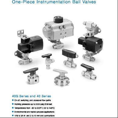
Swagelok Ball Valve 4g5e2o
July 2022 0
2inch Richter Ball Valve 6h3na
December 2019 30More Documents from "Kannaphat Wattanaphan" f6e4y