Wacker Neuson Rd 16 0171742en_001rep 595m64
This document was ed by and they confirmed that they have the permission to share it. If you are author or own the copyright of this book, please report to us by using this report form. Report 2z6p3t
Overview 5o1f4z
& View Wacker Neuson Rd 16 0171742en_001rep as PDF for free.
More details 6z3438
- Words: 2,361
- Pages: 108
www.wackergroup.com
0171742en 0108
Roller
RD 16
REPAIR MANUAL
0
1
7
1
7
4
2
E
N
001
RD 16 Repair
Foreword
Foreword
RD 16-90
0620060
RD 16-100
0620402
RD 16IRH-90
0620127
-
---
Keep a copy of the Operator’s Manual with the machine at all times. Use the separate Parts Book supplied with the machine to order replacement parts. Refer to the separate Repair Manual for detailed instructions on servicing and repairing the machine. If you are missing any of these documents, please Wacker Corporation to order a replacement or visit www.wackergroup.com. When ordering parts or requesting service information, be prepared to provide the machine model number, item number, revision number, and serial number. This manual provides information and procedures to safely operate and maintain the above Wacker model(s). For your own safety and to reduce the risk of injury, carefully read, understand, and observe all instructions described in this manual. Wacker Corporation expressly reserves the right to make technical modifications, even without notice, which improve the performance or safety standards of its machines. The information contained in this manual is based on machines manufactured up until the time of publication. Wacker Corporation reserves the right to change any portion of this information without notice. All rights, especially copying and distribution rights, are reserved. Copyright 2007 by Wacker Corporation. This publication may be reproduced through photocopying by the original purchaser of the machine. Any other type of reproduction is prohibited without express written permission from Wacker Corporation. Any type of reproduction or distribution not authorized by Wacker Corporation represents an infringement of valid copyrights, and violators will be prosecuted. Engine exhaust, some of its constituents, and certain vehicle components, contain or emit chemicals known to the State of California to cause cancer and birth defects or other reproductive harm. State Health Safety Codes and Public Resources Codes specify that in certain locations spark arresters be used on internal combustion engines that use hydrocarbon fuels. A spark arrester is a device designed to prevent accidental discharge of sparks or flames from the engine exhaust. Spark arresters are qualified and rated by the United States Forest Service for this purpose. In order to comply with local laws regarding spark arresters, consult the engine distributor or the local Health and Safety . wc_tx000761gb.fm
3
Foreword
RD 16 Repair All trademarks referenced in this manual are the property of their respective owners.
wc_tx000761gb.fm
4
RD 16 Repair
Table of Contents
1.1 1.2 1.3 1.4 1.5 1.6
Checking the Wiring to the Starter Solenoid ........................................ 8 Checking the 30A Main Fuse ............................................................... 9 Checking the Key Switch .................................................................... 10 Checking the Crank Relay .................................................................. 11 Checking the Neutral Switch .............................................................. 12 Checking the Neutral Relay ................................................................ 13
2.1 2.2 2.3 2.4 2.5 2.6 2.7 2.8
Drive System Overview ...................................................................... 14 Adjusting the Drive Control Cable ...................................................... 15 Checking the Brake Release Solenoid Valve ..................................... 16 Checking the Brake Switch ................................................................ 18 Checking the Drive System Operating Pressure ................................ 19 Checking the Drive System Relief Pressure ...................................... 20 Checking the Drive Motors ................................................................. 21 Manually Releasing the Parking Brakes ............................................. 23
3.1 3.2 3.3 3.4
Vibration System Overview ................................................................ 24 Troubleshooting a System that Vibrates Poorly ................................. 25 Checking the Vibration Solenoid Valve .............................................. 27 Checking the Vibration Switch ............................................................ 29
4.1 4.2 4.3 4.4
Troubleshooting the Spray System .................................................... 30 Checking Power to the Spray Bar Pump ............................................ 31 Checking the Pump Timer Module ..................................................... 32 Checking the Spray System Switch ................................................... 33
wc_br0171742en_001TOC.fm
5
Table of Contents
RT /...
5.1
Checking the Steering System ............................................................34
6.1 6.2 6.3 6.4 6.5 6.6 6.7 6.8 6.9 6.10 6.11 6.12 6.13 6.14 6.15 6.16 6.17 6.18 6.19 6.20 6.21 6.22 6.23 6.24 6.25 6.26 6.27
Tools Required for Disassembly/Assembly .........................................35 Information Regarding Replacement Parts .........................................35 Information Regarding Threadlocking Compounds ( ) ........................35 Removing the Articulating t ...........................................................36 Installing the Articulating t .............................................................38 Removing Either Drum ........................................................................40 Installing Either Drum ..........................................................................43 Removing a Drive Motor ......................................................................45 Installing a Drive Motor ........................................................................46 Installing the Exciter ............................................................................49 Disassembling the Exciter Bearings ....................................................51 Assembling the Exciter Bearings .........................................................54 Removing the Cooling Fan ..................................................................56 Installing the Cooling Fan ....................................................................58 Removing the Radiator/Oil Cooler .......................................................60 Installing the Radiator/Oil Cooler .........................................................62 Removing the Exciter Pump ................................................................64 Installing the Exciter Pump ..................................................................66 Removing the Drive Pump ..................................................................67 Installing the Drive Pump ....................................................................69 Removing the Hydraulic Oil Tank ........................................................71 Installing the Hydraulic Oil Tank ..........................................................73 Removing the Engine ..........................................................................74 Installing the Engine ............................................................................77 Removing the Steering Valve ..............................................................80 Removing the Fuel Tank .....................................................................82 Installing the Fuel Tank .......................................................................84
7.1 7.2 7.3
Engine .................................................................................................86 Roller ...................................................................................................87 Lubrication ...........................................................................................87
wc_br0171742en_001TOC.fm
6
RD 16 Repair 7.4 7.5 7.6 7.7 7.8 7.9 7.10 7.11 7.12 7.13 7.14 7.15 7.16 7.17
Table of Contents
Dimensions—RD 12 / RD 16-90 / RD 16 IRH .................................... 88 Dimensions—RD 16-100 .................................................................... 89 Sound Measurements ........................................................................ 90 Measurements of Operator Exposure to Vibration ............................. 91 Hydraulic Schematic—RD 12/RD 12A ............................................... 92 Hydraulic Schematic Components—RD 12/RD 12A .......................... 93 Hydraulic Schematic—RD 16 ............................................................. 94 Hydraulic Schematic Components—RD 16 ....................................... 95 Electric Schematic—RD 12 ................................................................ 96 Electrical Schematic Components—RD 12 ........................................ 97 Electrical Schematic—RD 12A ........................................................... 98 Electrical Schematic Components—RD 12A ..................................... 99 Electrical Schematic—RD 16 ........................................................... 100 Electrical Schematic Components—RD 16 ...................................... 102
wc_br0171742en_001TOC.fm
7
Engine Start System Troubleshooting
RD 16 Repair
Before troubleshooting engine starting issues, check the battery and the cable connections to the battery. The battery must be fully charged (approximately 12V). Complete the troubleshooting in the following sequence: 1. Check the wiring to the starter solenoid. 2. Check the 30A main fuse. 3. Check the key switch. 4. Check the crank relay. 5. Check the neutral switch. 6. Check the neutral relay.
Machine shut down Black wire #66 delivers 12VDC to the starter solenoid. If this wire is broken or disconnected, the engine will not start. Follow the procedure below to check the wiring to the starter solenoid. 1. Open the hood and locate the starter solenoid
.
2. Check the connection and condition of black wire #66.
Continue
Reconnect or repair black wire #66.
The wiring to the starter solenoid has now been checked.
wc_tx000697gb.fm
8
RD 16 Repair
Engine Start System Troubleshooting
Machine shut down There are three fuses that protect the circuitry on the RD 16: 30A lights 30A main 20A throttle pull Follow the procedure below to check the 30A main fuse. 1. Open the hood and locate the fuse carrier.
2. Remove the protective cover from the fuse carrier 3. Check the condition of the 30A main fuse
Continue
.
Replace the 30A fuse with one of same size and rating.
4. Re-install the protective cover to the fuse carrier. The 30A fuse has now been checked.
wc_tx000697gb.fm
.
9
Engine Start System Troubleshooting
RD 16 Repair
Multimeter Fully-charged (approximately 12V) battery Functioning main fuse The key switch is a three-position switch: ON, START, and OFF. When in the START position, the key switch directs battery voltage to the crank relay. Follow the procedure below to check the key switch. 1. Remove the screws that secure the plate remove the plate.
to the back of the control and
2. Using the multimeter, check the voltage between the BAT terminal (b) of the key switch and ground. For easier measuring, remove the plug and measure voltage at the plug.
Continue
Check the continuity of red wire #33 between key switch and 30A main fuse. Repair red wire #33 as needed.
3. Place the key switch in the START position.
4. Check the voltage between the “S” terminal of the key switch and ground.
The key switch is not the problem.
The key switch has failed; replace it.
5. Re-install the plate to the back of the control console. The key switch has now been checked. wc_tx000697gb.fm
10
RD 16 Repair
Engine Start System Troubleshooting
Multimeter Fully-charged (approximately 12V) battery Functioning main fuse Functioning key switch The coil of the crank relay is energized when the key switch is in the START position. Follow the procedure below to check the crank relay. 1. Open the hood and locate the crank relay
.
2. Check the voltage between terminal 30 (red wire #32) and ground. This test may be done at plug with it disconnected from the crank relay.
Continue
Repair red wire #32.
3. With the key switch in the START position, check the voltage between terminal 86 (black wire #34) and ground. This test may be done at plug with it disconnected from the crank relay.
Continue
Repair black wire #34.
4. With the key switch in the START position, check the voltage between terminal 87 and ground (pink wire #60). For this test, plug must be connected to the crank relay. Position the plug as shown to allow access to terminal 87.
The crank relay is OK.
The crank relay has failed; replace it.
The crank relay has now been checked.
wc_tx000697gb.fm
11
Engine Start System Troubleshooting
RD 16 Repair
Multimeter Fully-charged (approximately 12V) battery Functioning main fuse Functioning key switch Seat platform in raised position. See section The neutral switch, when closed (control lever in NEUTRAL position), allows voltage to the neutral relay. Follow the procedure below to check the neutral switch. 1. Locate the connector
for the neutral switch and disconnect it.
2. Place the control lever in the NEUTRAL position. 3. With the key switch in the START position, check the continuity between the pins of the connector (green and white wires).
Continue
The neutral switch has failed; replace it.
4. Place the control lever in the FORWARD or REVERSE position. 5. With the key switch in the START position, check the continuity between the pins of the connector (green and white wires).
The neutral switch has failed; replace it.
Continue
6. Repeat the test with the control lever in the REVERSE position.
The neutral switch has failed: replace it.
7. Reconnect the wiring. 8. Lower and secure the seat platform. The neutral switch has now been checked. wc_tx000697gb.fm
12
The neutral switch is OK.
RD 16 Repair
Engine Start System Troubleshooting
Multimeter Fully-charged (approximately 12V) battery Functioning main fuse Functioning crank relay Functioning neutral switch
The neutral relay relays battery voltage to the starter solenoid. Follow the procedure below to check the neutral relay. 1. Open the hood and locate the neutral relay
.
2. Place the key switch in the START position. 3. Check the voltage between terminal 30 (pink wire #60) and ground. This test may be done at plug with it disconnected from the neutral relay.
Continue
Repair pink wire #60.
4. Check the voltage between terminal 86 (green wire #61) and ground. This test may be done at plug with it disconnected from the neutral relay.
Continue
Repair red wire #31.
5. Check the voltage between terminal 87 (black wire #66) and ground. For this test plug must be connected to the crank relay. Position the plug as shown to allow access to terminal 87.
The neutral relay is OK.
The neutral relay has failed; replace it.
The neutral relay has now been checked.
wc_tx000697gb.fm
13
Drive System
RD 16 Repair
The hydraulic system is powered by two pumps (exciter and drive) mounted in tandem—connected along their shafts through a solid-mounted coupling—and driven directly by the engine crankshaft through a flex coupling. The drive pump is a variable displacement, axial piston pump and includes an integral charge pump. Flow through the drive pump is controlled by varying its displacement through the movement of the control lever coupled to the pump’s control shaft. This allows a full range of operating speeds in both forward and reverse. There are two drive motors—one mounted to each drum. The drive motors are plumbed in series. Each drive motor is equipped with Spring Activated Hydraulically Released (SAHR) brake. The hydraulic tank is equipped with a strainer at the fill port to trap large objects or particles which may accidentally fall into the tank while adding hydraulic fluid. Additional system protection is provided by a suction filter mounted in-line with the exciter pump inlet. The hydraulic system is protected by a return-line filter which removes dirt particles down to 10 microns and includes a flow by for cold weather start-up. When troubleshooting drive system problems, do so in the following sequence: 1. Check the function of the drive control cable. 2. Check the brake release solenoid valve. 3. Pressure test the drive pump and relief valve. 4. Check the drive motors.
wc_tx000783gb.fm
14
RD 16 Repair
Drive System
If the roller tends to drift in either direction when the forward/reverse control is in NEUTRAL, the drive control cable must be adjusted. Machine on a hard, level surface Engine running Forward/reverse control in the NEUTRAL position Follow the procedure below to adjust the drive control cable. 1. Loosen the lock nut .
2. Move the turnbuckle as needed until machine movement stops. If adjusting the turnbuckle does not achieve the desired results, a gross adjustment can be made at the nut and then fine-tuned as described above. The drive control cable has now been adjusted.
wc_tx000783gb.fm
15
Drive System
RD 16 Repair
The brake release valve controls hydraulic pressure to the brakes. If this solenoid valve is disconnected or malfunctioning, the brakes will not release and the machine will not move. Drums chocked Assistant Follow the procedure below to check the brake release valve. 3. Open the engine compartment and locate the brake release valve
.
4. Remove the nut that secures the solenoid to the valve and slide the solenoid from the valve. 5. Start the engine—the operator must remain seated in the operator’s seat. 6. Place the brake switch in the OFF position. 7. Check the magnetic force created by the solenoid by having an assistant place a piece of ferrous metal such as a screwdriver inside the solenoid.
The solenoid is functioning.
wc_tx000783gb.fm
16
Continue.
RD 16 Repair
Drive System
8. Remove the wiring connector
from the solenoid.
9. Check the voltage at the wiring connector (with the engine running, operator seated, and brake switch in OFF position).
The solenoid has failed; replace it.
Check the function of the brake switch.
The brake release valve has now been checked.
wc_tx000783gb.fm
17
Related Documents c2h70
Wacker Neuson Rd 16 0171742en_001rep 595m64
November 2019 30
Manual Torre Wacker Neuson 3l6p44
May 2021 0
Wacker 4t3r2u
December 2019 26
Proceso Wacker 5d5c4s
February 2021 0
Rd 2i404y
June 2021 0
Wacker Manual 1t5lp
November 2019 26More Documents from "Khaled Kamel" 4b6b6p
Wacker Neuson Rd 16 0171742en_001rep 595m64
November 2019 30
Cat 3500b Application Guide n3r3u
August 2020 0
14m Electric Schematic 1b1x4f
June 2020 3
Terex Genie Rl4000 Service Manual 1t264v
November 2019 81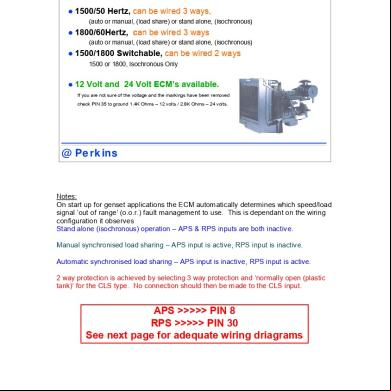
1300edi Wiring Diagrams For Genset Applications 5o35h
October 2019 37