Cat 3500b Application Guide n3r3u
This document was ed by and they confirmed that they have the permission to share it. If you are author or own the copyright of this book, please report to us by using this report form. Report 2z6p3t
Overview 5o1f4z
& View Cat 3500b Application Guide as PDF for free.
More details 6z3438
- Words: 1,480
- Pages: 9
3500B Application Guide
3500B Basic Engine The 3500B Basic Engine application is a software training module for the Caterpillar Engine Simulator’s Electronic Training Aid program. This module provides information about genset, marine, and machine engine control systems. The following pages include specifications for Simulator setup and general information.
The Caterpillar Engine Simulator 3500B-1
3500B Application Application Information
EUI System Specs ECM
7X6322
ECM Harness
128-1171
ECM Harness Port
Connect to Ports A & B
Personality Module
35BTAID-01
Engine Component Voltage Selector
Set to local voltage (115Vac OR 220Vac)
ECM Power Selector
24Vdc
Required Connector Cables
J1, J2, J3, RS232
ECM Harness Port Connections Exhaust Temperature Breakout
Connector B
Connector A
Timing Cal Connector
The Caterpillar Engine Simulator 3500B-2
3500B Application Application Information
Engine Sensor Locations
Jacket-Water Temperature Sensor
Speed/Timing Sensor
Turbo Outlet Pressure Sensor
Atmospheric Pressure Sensor
Turbo Inlet Left Pressure Sensor
Oil Pressure Sensor Crankcase Pressure Sensor
Turbo Inlet Right Pressure Sensor
Instrument
Tachometer
Ether Manual
Not Used
Load
Throttle
Ignition
Crank
The Caterpillar Engine Simulator 3500B-3
3500B Application Application Information
Electrical Control System Diagram Electronic Control Module Disconnect Seitch
Electronic Unit Injectors (8)
24V + P26 TPC Service Probe Access Oil Pressure Sensor (filtred) P22/J22 Turbo Outlet Pressure Sensor
P23/J23
Engine Control 15A Breaker
Right Turbo Inlet Pressure Sensor P25/J25 Engine Harness Left Turbo Inlet Pressure Sensor
P28/J28
Speed/Timing Sensor
P20/J20
Crankcase Pressure Sensor
P29/J29
Left Turbine Inlet Exhaust Temperature Sensor
J30/P30
Right Turbine Inlet Exhaust Temperature Sensor
J31/P31
Vehicle Main Power Relay
Ground Bolt
Keyswitch
CAT Data Link
Jacket-Water Temperature Sensor J21/P21 Atmospheric Pressure Sensor
Service Tool Vehicle Harness
Ether Manual Switch
Ether Hold Relay
Ether Start Relay J36/P21
J37/P37
P27/J27
The Caterpillar Engine Simulator 3500B-4
3500B Application Application Information
Using the 3500B Training Aid Application The 3500B Training Aid is intended to be used with the Caterpillar Electronic Service Tool for full functionality. Automatic Ether Injection On the 3500B engine, automatic ether injection is controlled by the ECM. The ECM monitors engine coolant temperature and determines when to inject ether. Drivers in the ECM are used to control relays that provide the high currents needed to activate the ether injection solenoid. Injector Electronic Trim 3500B engines are equipped with an injector electronic trim feature. When an injector is installed in the engine, the mechanic can read a four digit trim code on the injector tappet and enter the code into the ECM using an Electronic Service Tool. The ECM can then optimize injection for that particular injector. Programmable Monitoring System Some 3500B engines include a programmable monitoring system feature. The ECM can monitor parameters and provide warnings, engine derates, and engine shutdowns depending on the status of the parameter. An ET service tool can be used to view and change the monitoring system settings. Usually there will be factory security on some monitoring system parameters, but for the purpose of this 3500B Training Aid, the security has been disabled. Crankcase Pressure Monitoring On 3500B engines, the ECM can monitor absolute crankcase pressure. Atmospheric pressure is then subtracted from absolute crankcase pressure to get gauge crankcase pressure. Gauge crankcase pressure is then used to trigger engine warnings, derates and shutdowns. In general, high crankcase pressure could indicate a problem with the engine’s pistons, rings, or liners. Exhaust Temperature Monitoring On 3500B engines, the ECM directly monitors the exhaust to turbo temperatures for each bank of cylinders (left and right). Exhaust temperatures are then used to trigger engine warnings, derates and shutdowns. High exhaust temperatures are usually the result of high altitude running or excessive inlet air restriction.
Demonstrating 3500B Engine Features
The Caterpillar Engine Simulator 3500B-5
3500B Application Application Information
Using the Sensor Overrides Sensor override slider controls are provided on the 3500B Training Aid Simulator screen. These overrides are used to set sensor values to higher or lower than normal settings. The slider controls can be accessed by pressing the “Manual Sensor Override” button on the Simulator screen. A window will appear that allows you to adjust oil pressure, coolant (Jacket Water) temperature , right and left exhaust temperature and crankcase temperature. The window can be closed and the override will remain active if “Override Values” is enabled. The “Manual Sensor Override” button turns red when any sensor is overridden. Override Sensor Values
C lose 56.280 [PSI]
102 [°F]
Jacket Oil Pressure Water [absolute] Temp
815 [°F]
Exhaust Temp. [R&L]
0.14 [PSI]
Clear Override
Crankcase Pressure [gauge]
Automatic Ether Injection The automatic ether injection system is simulated on the PC screen with a picture of the two control relays and a picture of the ether solenoid and bottle. When the ECM energizes the relays to inject ether, the relays and solenoid on the PC screen turn red. Ether Relays
Ether Solenoid
System Control 1
Ether Start
Ether Hold
0
Manual Sensor Override
Ether Auto/Manual
The ECM will not inject ether unless the coolant temperature is low. To use the sensor overrides to set the coolant temperature low before starting the engine, follow these steps:
The Caterpillar Engine Simulator 3500B-6
3500B Application Application Information
1.
At the Simulator screen, select ON-SCREEN.
2.
Set the Component ignition keyswitch to ON.
3.
Click once on the MANUAL SENSOR OVERRIDE button. The Override Sensors window will appear.
4.
In the Override Sensors window, set the coolant temperature to the bottom of the slider control (-40°F). Lower temperatures cause the ECM to automatically inject ether longer.
5.
Depress and release the CRANK button on the keyswitch.
6.
Observe the ether relays and solenoid turn red, indicating that they are energized.
7.
Once automatic injection is completed, depress and hold the ETHER MANUAL switch to inject more ether.
Injector Electronic Trim Electronic trim codes can be entered for each cylinder using the ET service tool. The Training Aid must be in the Simulator mode with the keyswitch turned ON so the ECM receives power. The ECM will accept trim codes while the engine is running or stopped. Refer to your ET manuals for more information about operating ET and entering injection trim codes.
The Caterpillar Engine Simulator 3500B-7
3500B Application Application Information
Programmable Monitoring System The programmable monitoring system can be viewed and changed during operation of the Training Aid. Depending on the monitoring system settings, the ECM may provide warnings (via ET), derate the engine, or shut the engine down during operation. The current status of all monitoring system warnings, derates and shutdowns appears near the top of the ET screen as a short text message. Status Monitor
Cat Electronic Status Monitor
F ile Diagnostics I nformation Service Status
Active Codes
Technician Status Utilities
Data Link Se t tings Help
Logged Codes
Configuration
Exit
Engine: 3508B Training Aid High Engine Coolant Temp 3508B Training Aid Group 1 Engine: 3508B Training Aid 13 PSI 1937 RPM 1937 RPM 214 93 112 100% 77
Groups . . .
M ore
Zoom In
H o ld
Boost Pressure Desired Engine Speed Engine Speed FRC Fuel Limit Fuel Position Rated Fuel Limit Throttle Position Percent Load
Print Engine 3508B Training Aid
The Caterpillar Engine Simulator 3500B-8
3500B Application Application Information
Note that the “Low System Voltage” warning will always be active due to the 12V system voltage on the Training Aid. This will not cause any operational problems. Low System Voltage Warning
Cat Electronic Technition- Monitoring System File Diagnostics I nformation Service Status
Active Codes
Desctiption Low System Voltage Warn Operator Low Engine Oil Pressure Warn Operator Engine Derate Engine Shutdown High Engine Coolant Temperature Warn Operator Engine Derate Engine Shutdown Low Engine Coolant Temperature Warn Operator Engine Overspeed Warn Operator Engine Shutdown High Air Filter Restriction Pressure Warn Operator Engine Derate
Utilities
Data Link Se t tings Help
Logged Codes
Configuration
Exit
State
Trip Point
Delay Time
On
24 Volts
5 Sec
On On On
None None None
1 Sec 1 Sec 1 Sec
On On On
216 Det F 221 Deg F 225 Deg F
5 Sec 5 Sec 5 Sec
On
167 Deg F
5 Sec
On On
2100 RPM 2200 RPM
0 Sec 0 Sec
On On
28” H20 28” H20
5 Sec 5 Sec Print
Change
Engine 3508B Training Aid Press the Change button to change a parameter state, trip, point, or delay time.
You can also view and change monitoring system setpoints for warnings, derates and shutdowns. In the Monitoring System window, click once on a parameter line to select it and click the CHANGE button. A window appears that allows you to change the state, trip point or delay time of the Monitoring System parameter. Then, by using the sensor overrides or other Simulator controls, you can demonstrate various warnings, derate and shutdown actions on the 3500B Training Aid. Example You can override coolant temperature to 103°C and then observe the warning appear on the ET screen after a one-second delay. You can also lengthen the delay time. The Caterpillar Engine Simulator 3500B-9
Related Documents c2h70
Cat 3500b Application Guide n3r3u
August 2020 0
3500b Engines Application And Installation Guide 2p415v
April 2020 21
Cat 3500b Generator Electrical System 2s1m4t
April 2020 22
Cat Filter And Filter Application Guide 1g362z
December 2019 120
Cat Extreme Application Grease - Arctic 234ck
February 2022 0
Cat Genset Guide 6g5p4j
April 2020 15More Documents from "Khaled Kamel" 4b6b6p
Wacker Neuson Rd 16 0171742en_001rep 595m64
November 2019 30
Cat 3500b Application Guide n3r3u
August 2020 0
14m Electric Schematic 1b1x4f
June 2020 3
Terex Genie Rl4000 Service Manual 1t264v
November 2019 81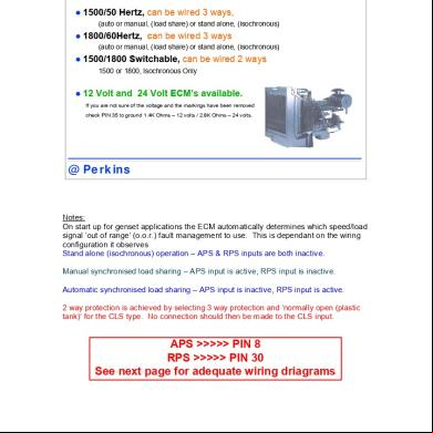
1300edi Wiring Diagrams For Genset Applications 5o35h
October 2019 37