Syswan Duolinks Sw24 Series Dual Wan Router Guide 3z6y7
This document was ed by and they confirmed that they have the permission to share it. If you are author or own the copyright of this book, please report to us by using this report form. Report 2z6p3t
Overview 5o1f4z
& View Syswan Duolinks Sw24 Series Dual Wan Router Guide as PDF for free.
More details 6z3438
- Words: 23,891
- Pages: 114
Duolinks SW24 Series
Guide
Syswan Technologies, Inc. 2050 Beavercreek Rd, Suite 101 #388 Oregon City, OR 97045 USA 1 - 877 - 6 - SYSWAN www.syswan.com
Copyright and Trademarks Copyright © 2007-2008 Syswan Technologies, Inc. All rights reserved. Brands and product names are trademarks or ed trademarks of their respective holders. Specifications are subject to change without notice. V1/RBEN
Table of Contents Purpose ...........................................................................................................................................................iv Audience..........................................................................................................................................................iv Document Layout.............................................................................................................................................iv Documentation updates...................................................................................................................................iv Technical ............................................................................................................................................iv 1. INTRODUCTION ......................................................................................................................................... 1 Overview.......................................................................................................................................................... 1 Main Features.................................................................................................................................................. 3 Internet Sharing Features................................................................................................................................ 4 Other Features................................................................................................................................................. 5 Package Contents ........................................................................................................................................... 7 Product Details ................................................................................................................................................ 7 2. BASIC SETUP........................................................................................................................................... 11 Overview........................................................................................................................................................ 11 Configuration Procedure................................................................................................................................ 12 3. ADVANCED PORT ................................................................................................................................... 25 Overview........................................................................................................................................................ 25 Port Options................................................................................................................................................... 25 Load Balancing .............................................................................................................................................. 28 Advanced PPPoE .......................................................................................................................................... 30 Advanced PPTP ............................................................................................................................................ 33 4. ADVANCED CONFIGURATION............................................................................................................... 35 Overview........................................................................................................................................................ 35 Host IP Setup................................................................................................................................................. 35 Routing .......................................................................................................................................................... 38 Virtual Servers ............................................................................................................................................... 39 i
Guide
© Syswan Technologies, Inc.
Special Applications....................................................................................................................................... 42 Dynamic DNS ................................................................................................................................................ 44 Multi DMZ ...................................................................................................................................................... 47 UPnP ............................................................................................................................................................. 48 NAT................................................................................................................................................................ 49 ARP Status .................................................................................................................................................... 51 Advanced Features........................................................................................................................................ 53 5. SECURITY MANAGEMENT ..................................................................................................................... 56 Overview........................................................................................................................................................ 56 URL Filter....................................................................................................................................................... 56 Access Filter .................................................................................................................................................. 58 Session Limit ................................................................................................................................................. 60 SysFilter Exception ........................................................................................................................................ 61 6. VPN CONFIGURATION............................................................................................................................ 62 Overview........................................................................................................................................................ 62 IPSec (IKE) Global Setting ............................................................................................................................ 63 IPSec Policy Setup ........................................................................................................................................ 65 VPN Mesh Group Configuration .................................................................................................................... 71 7. QOS CONFIGURATION ........................................................................................................................... 73 Overview........................................................................................................................................................ 73 QoS Setup ..................................................................................................................................................... 73 QoS Policy Configuration .............................................................................................................................. 74 8. DNS CONFIGURATION............................................................................................................................ 76 Overview........................................................................................................................................................ 76 Configure DNS............................................................................................................................................... 77 Map Host URL ............................................................................................................................................... 79 9. MANAGEMENT ASSISTANT ................................................................................................................... 81 ii
Guide
© Syswan Technologies, Inc.
Overview........................................................................................................................................................ 81 Setup .................................................................................................................................................. 81 Email Alert ..................................................................................................................................................... 82 SNMP ............................................................................................................................................................ 84 Syslog ............................................................................................................................................................ 85 Diagnostic Tools ............................................................................................................................................ 87 Upgrade Firmware ......................................................................................................................................... 88 10. ADVANCED LAN CONFIGURATION .................................................................................................... 89 Overview........................................................................................................................................................ 89 Existing DH Server ................................................................................................................................... 89 Routing .......................................................................................................................................................... 89 11. OPERATION AND STATUS ................................................................................................................... 93 Operation ....................................................................................................................................................... 93 System Status................................................................................................................................................ 93 WAN Status ................................................................................................................................................... 96 NAT Status .................................................................................................................................................... 97 APPENDIX A SPECIFICATIONS ................................................................................................................. 99 APPENDIX B WINDOWS T/IP SETUP.................................................................................................. 100 Overview...................................................................................................................................................... 100 T/IP Settings ........................................................................................................................................... 100 APPENDIX C TROUBLESHOOTING ......................................................................................................... 107 Overview...................................................................................................................................................... 107 General Problems........................................................................................................................................ 107 Internet Access ............................................................................................................................................ 107
iii
Guide
© Syswan Technologies, Inc.
Purpose This document explains how to configure and use the Duolinks SW24 Series Load Balancers to optimize your Internet activities.
Audience This document is intended for all s of the Duolinks SW24 Series Load Balancers, from high level s to end-s having basic knowledge of computers and the Internet.
Document Layout This documentation is the Guide for all versions of the Duolinks SW24 Series Load Balancers. Some of the advanced features described in this Guide are specific to certain Duolinks SW24 Series Load Balancer models. Such as: VPN : Duolinks SW24 VPN and Duolinks SW24 VPN Plus models only. VPN Failover : Duolinks SW24 VPN and Duolinks SW24 VPN Plus models only. VPN Mesh : Duolinks SW24 VPN Plus model only. Inbound load balancing / Built-in DNS Server : Duolinks SW24 VPN Plus model only. Depending on your Duolinks SW24 model, some parts of this documentation may not apply to you. Advanced functionalities which are specific to certain models are clearly indicated at the beginning of the relevant Chapter.
Documentation updates At Syswan Techologies our R&D team works each day to provide our customers with superior quality products. Features and firmware versions described in this documentation may not match the current releases. New and enhanced features may be added to the Duolinks SW24 Series Load Balancers which might not be covered or explained in this documentation. Please visit our web site regularly for an updated version of this Guide and for the latest firmware releases that may have become available after your purchase.
Technical Syswan Technologies offers free technical for all problems related to Syswan products. Technical can be reached by phone, email or you may use our online knowledgebase for extensive online information on our product range and basic networking guidelines. Phone :
USA/Canada – 1-877-7-SYSWAN International – 1-541-393-2222
Email : [email protected] Go to http://www.syswan.com/knowledgebase to access our knowledgebase.
iv
Guide
© Syswan Technologies, Inc.
Syswan Duolinks SW24 Series
1. Introduction Congratulations on purchasing your Syswan Duolinks SW24 Series Load Balancer. The Duolinks SW24 Series Load Balancers provides uninterrupted Internet connectivity for multiple computers for SOHO, SMB and corporate networks. This chapter briefly describes the features of the Duolinks SW24 Series Load Balancers with more detailed information in the chapters ahead.
Overview The Syswan Technologies Duolinks SW24 Series high performance Dual WAN router provides a fast, secure and reliable connection to the Internet. Using state of the art automatic redundancy and bandwidth load balancing technologies, it allows fast, secure and reliable Internet connectivity to all networked computers in home offices, small offices and small-to-medium sized organizations. With the addition of a second Internet broadband connection, the Duolinks SW24 ensures your network not only remains connected to the Internet, but all Internet traffic is constantly managed reliably and securely even during periods of high traffic and heavy workloads.
Syswan Duolinks SW24 Series Load Balancer - example configuration
Page 1
Guide
© Syswan Technologies, Inc.
Syswan Duolinks SW24 Series Maximize available bandwidth The Duolinks SW24 has two WAN ports that allows connection to two separate broadband links, including xDSL, Cable, Satellite or Leased (T1) links. This design feature allows for intelligent load balancing to maximize the available bandwidth whilst managing and prioritizing traffic flow for fast and redundant Internet connectivity. Easy to install and manage The Duolinks SW24 is easy to configure locally or remotely using your Internet browser via a standard (HTTP) or a secure management interface (HTTPS). Built-in NAT, SPI Firewall, DH server, URL Blocking and Access Filters amongst other security options provide the highest industry standards to easily build a fast, reliable and secure network configuration. With its easy-to-use Configuration Interface, you can set Alerts to be sent via email, System Logs to be sent to a Syslog server, as well as monitor network activity via SNMP. Flexible configurations The flexible network configuration capabilities of the Duolinks SW24 allows it to be used in networks which Static Routing, RIP or Dynamic Routing. With UPnP you can automatically open and close networking ports as required by certain applications. QoS helps give priority to critical traffic on your network taking advantage of the maximum available bandwidth at all times. With these powerful features, the Duolinks SW24 can be quickly and easily integrated into any network. As more people rely on the Internet for communication, so too does the need to rely on scalable, secure and fast Internet connectivity. This means that there is no longer the need to limit your Internet needs with just one ISP. The Duolinks SW24 resolves this issue by maximizing the benefits of two different ISP’s whilst minimizing the need for costly upgrades and changes in existing network infrastructure. Secure IPSec Virtual Private Networking (VPN) The Virtual Private Network (VPN) capability can maintain up to 25 encrypted VPN tunnels simultaneously and provides remote offices and traveling s with the ability to connect securely to your network. When interconnecting two remote networks, the VPN failover technology of the Duolinks SW24 VPN automatically and seamlessly switches any active LAN-to-LAN VPN tunnels to the second ISP link when the primary ISP link fails. The IPSec implementation of the Duolinks SW24 VPN provides industry standard security with DES, 3DES or AES (128-bit) encryption and MD5 or SHA hashing algorithm for authentication. Intelligent DNS load balancing The DNS load balancing feature of the Duolinks SW24 VPN Plus acts as an authoritative Domain Name Server (DNS) for your domains hosted on your network. Intelligent inbound DNS load balancing and failover features not only increases the available bandwidth to your remote Internet s, but also ensures your Websites and other Internet services are always running in a failsafe and secure environment even with the added risks of broadband outages. The Duolinks SW24 VPN Plus can host up to 6 domains (SOA entries). It offers up to 2 local or remote mail exchange (MX) entries and up to 30 different services (type A DNS entries) per domain, each pointing to one or more servers on your local network. VPN Tunnel Clustering The VPN Tunnel Clustering feature of the Duolinks SW24 VPN Plus router allows for VPN tunnels to be configured into a Meshed Group which is then perceived as a single VPN tunnel. Its built-in VPN failover architecture ensures that the clustered VPN tunnels between networks remains fully functional even in the event of a failing WAN link at the local or remote end.
Page 2
Guide
© Syswan Technologies, Inc.
Syswan Duolinks SW24 Series
Main Features
Intelligent Load Balancing Use two WAN ports simultaneously to increase the available bandwidth. Set the load balancing values for each WAN port individually and configure the load balancing algorithm to suit your needs.
Multiple Connection Options Use broadband access from any broadband provider including Leased links (T1). All standard xDSL, Cable and Satellite modems and connection methods are ed, including Fixed IP, Dynamic IP, PPPoE, multiple-session PPPoE and PPTP.
Secure Management Secure access to the configuration interface locally from within your network or remotely via the Internet.
SPI Firewall The industry standard protection for any network using built-in advanced Stateful Packet Inspection technology against malicious attacks.
Access Filters and URL Blocking Controls Internet access and available applications for network s. Up to five groups can be defined with each group assigned different access rights.
Multi DMZ s up to 8 Static IP Addresses per WAN port.
Virtual Servers Allows remote s to access servers on your network. Easily enable standard services such as Web, FTP or Email or define your own servers and services.
Special Applications Manage applications which do not directly work behind a firewall (example: online games).
Dynamic DNS Allows the use of a Domain Name even when a fixed IP Address is not available.
QoS (Quality of Service) Gain control over critical applications by asg priority to your network traffic. This function will make specified packets with higher priority for -through before low priority packets. This is useful if you use real-time applications like Internet phone, video conference,. etc.
UPnP (Universal Plug and Play) By enabling UPnP (Universal Plug & Play), the Duolinks SW24 Series Load Balancer will become one of the network devices. Useful for discovery and control of network devices, such as Internet gateways.
Virtual Private Network (VPN) - Duolinks SW24 VPN and SW24 VPN Plus only Up to 25 simultaneous Remote-to-LAN or LAN-to-LAN IPSec VPN tunnels with VPN Clustering.
DNS Load Balancing (Inbound) - Duolinks SW24 VPN Plus only Built-in authoritative Domain Name Server (DNS) with inbound load balancing and DNS failover.
Page 3
Guide
© Syswan Technologies, Inc.
Syswan Duolinks SW24 Series
Internet Sharing Features
Shared Broadband Internet Access LAN s can access the Internet through the Syswan Duolinks SW24 Series Load Balancer by sharing one (1) or two (2) Broadband modems and connections.
s all common Connection Methods All popular DSL, Cable Modems and connection methods are ed, including Fixed IP, Dynamic IP, PPPoE, and PPTP.
PPPoE Session Management Multiple PPPoE sessions are ed. You can choose to “map” sessions to individual PCs.
Multiple IP Address If your ISP allocates multiple IP addresses, you can “map” up to eight (8) public IP addresses to individual PCs.
Special Applications This feature allows you to use some non-standard applications, where the port number used for the response is different to the port number used by the sender.
Virtual Servers This feature allows Internet s to access Internet servers on your LAN. For standard servers such as Web, FTP or E-Mail servers, only the IP address of the server PC is required. Optionally, you can also define you own Server types.
Multiple DMZ A "DMZ" PC will receive incoming connection requests, which would otherwise be blocked. For each IP address allocated by your ISP, a separate "DMZ" PC can be specified. So if your ISP has given you multiple IP addresses, you can have multiple “DMZ” PCs. Each “DMZ” PC has unrestricted 2-way Internet access, providing the ability to run programs that are otherwise incompatible with NAT routers (like the Syswan Duolinks SW24 Series Load Balancer).
Access Filter The Network can use the Access Filter to gain fine control over Internet access and applications available to LAN s. Five (5) groups are available, and each group can have different access rights.
Built-in DNS server - Duolinks SW24 VPN Plus only This feature is available only on the Syswan Duolinks SW24 VPN Plus Load Balancer. The Duolinks SW24 VPN Plus has a built in DNS server. This feature allows you to setup DNS and to provide Inbound and outbound load balancing features to s.
URL Filter This feature blocks LAN s from accessing undesirable web sites. You can even have different settings for different groups of PCs.
Session Limit With the Session Limit feature, if the numbers of new sessions for the system exceeds the maximum sampling time, any new session in the system will be dropped.
Page 4
Guide
© Syswan Technologies, Inc.
Syswan Duolinks SW24 Series
System Filter Exception This feature ensures that every packet with an unrecognized port will be rejected so as to prevent access to port scanning programs from hackers. However, in some situations this may incur problems with some servers (e.g. SMTP server port 113) or WAN clients who require a response packet to the availability of their communication peers.
IPSec VPN (Virtual Private Network) - Duolinks SW24 VPN and SW24 VPN Plus only This feature is available only on the Syswan Duolinks SW24 VPN and the Syswan Duolinks SW24 VPN Plus Load Balancers. is provided for up to 25 IPSec VPN tunnels with VPN failover and back-up mechanisms.
IPSec VPN Mesh Groups - Duolinks SW24 VPN Plus only This feature is available only on the Duolinks SW24 VPN Plus Load Balancers. The Duolinks SW24 VPN Plus Load Balancer s VPN Load Balancing with a mesh group configuration.
Other Features
4-Port Ethernet Switch The Duolinks SW24 Series Load Balancers incorporate a 4-port 10 /100BaseT switch, making it easy to create or extend your LAN.
DH Server Dynamic Host Configuration Protocol provides a dynamic IP address to PCs and other devices upon request. The Duolinks SW24 Series Load Balancers can act as DH Servers and provide dynamic IP addresses to PCs and devices on your local LAN.
Multi Segment LAN LANs containing one or more segments are ed, via the Duolinks SW24 Series Load Balancer's built-in static routing table and “LAN Any IP” options.
ARP proxy The ARP proxy feature allows you to assign an external (Internet) IP address to the Duolinks SW24 Series Load Balancer's LAN port. This allows servers on your LAN to have external (Internet) IP addresses.
Easy Setup Use your favorite web browser for configuration.
Secure SSL access The Duolinks SW24 Series Load Balancers offer secure HTTPS (SSL) encryption by defaut when accessing the management GUI. You may optionally deactivate this feature and use a classic (HTTP) access if needed.
Remote Management The Duolinks SW24 Series Load Balancer can be managed from any PC on your LAN. If an Internet connection exists, it can also (optional) be configured via the Internet.
protected Configuration Optional protection is provided to prevent unauthorized s from modifying the configuration data and settings.
Page 5
Guide
© Syswan Technologies, Inc.
Syswan Duolinks SW24 Series
HTTPS (SSL) or HTTP Firmware Upgrade and backup The web management feature allows you to use HTTPS or HTTP upgrade new firmware and backup system configuration from local or remote sites. This is enabled via “Remote upgrade” and “Remote setup” options available on the Setup page.
7Email Alerts It will send a warning email to the system , if one of the WAN ports was disconnected when both WAN ports are enabled.
Syslog Generates real time system information on a web page or sends system logs to a syslog server. Useful for monitoring the device.
Scheduled Events The Duolinks SW24 Series Load Balancer can be set to automatically reboot once a day at a specified time.
Page 6
Guide
© Syswan Technologies, Inc.
Syswan Duolinks SW24 Series
Package Contents The following items should be included with your purchase:
Duolinks SW24 Series Load Balancer
External power adapter
Two 5 feet Ethernet cables
Quick Installation Guide
CD-Rom containing the guides and tools.
Rack mounts (19”1U).
If any of the above items are damaged or missing, please your dealer immediately.
Product Details Front
Syswan Duolinks SW24 Series Load Balancer Front s
Operation of the Front LEDs is as follows: LAN LINK/ACT
ON – Physical connection or data in/out. OFF – No physical connection.
10M/100M
ON – The corresponding LAN port is using 100BaseT. OFF – 10BaseT connection on the corresponding LAN port or no connection.
Page 7
Guide
© Syswan Technologies, Inc.
Syswan Duolinks SW24 Series
WAN LINK/ACT
ON – Physical connection to the Broadband modem on WAN port 1/2 established. OFF – No physical connection on WAN port 1/2.
10M/100M
ON – Physical connection using 100BaseT on WAN port 1/2 established. OFF – 10BaseT connection or no connection on WAN port 1/2.
System Power
OFF – No power. ON – Normal Operation
Status
OFF – Normal operation. ON – Firmware not loaded or Hardware error. Blinking – Data in/out
Some Status and Error conditions are indicated by combinations of LEDs, as shown below
LED Action
Condition
WAN1 LINK/ACT & 10M/100M LEDs flash alternatively.
Firmware in progress.
WAN1 LINK/ACT & 10M/100M LEDs flash concurrently.
MAC address not assigned.
WAN1 LINK/ACT & 10M/100M LEDs solid On.
SDRAM error.
WAN2 LINK/ACT & 10M/100M LEDs solid On.
Timer/Interrupt error.
LAN1 LINK/ACT & 10M/100M LEDs solid On.
LAN/WAN error.
If your discover any of the above error conditions, please our team for assistance.
Page 8
Guide
© Syswan Technologies, Inc.
Syswan Duolinks SW24 Series
Rear
Duolinks SW24 Series Rear
DC 5V
Connect the supplied power adapter here.
WAN 2
Connect the 2nd Broadband Modem here, if available.
Reset Button
When pressed and released, the Duolinks SW24 Series Load Balancer will reboot (restart) within 1 second. It resets to default (factory reset) if pressed for over 3 seconds.
LAN Ports
Connect the PCs to these ports. Both 10BaseT and 100BaseT connections can be used simultaneously. Note: Any port will automatically operate as an "Uplink" port if required. Just use a LAN cable to connect to a port on another hub.
WAN 1
Connect the primary Broadband Modem here.
Default Settings When the Duolinks SW24 Series Load Balancer has finished booting after a factory reset, all configuration settings will be set to factory default, including:
IP Address set to its default value of 192.168.1.1, with a Network Mask of 255.255.255.0
DH Server is enabled
Name:
blanked (no )
Page 9
Guide
© Syswan Technologies, Inc.
Syswan Duolinks SW24 Series
TFTP This setting should be used only if your Duolinks SW24 Series Load Balancer is unstable and if you wish to restore it by ing a new firmware version. Follow this procedure: 1. Power On your Syswan Duolinks SW24 Series Load Balancer. 2. Use the supplied Windows TFTP utility or a TFTP client program to apply the new firmware. If using the supplied Windows TFTP program, the software screen will look like the following example.
TFTP utility
Enter the name of the firmware upgrade file on your PC, or click Browse to locate the file.
Enter the LAN IP address of the Duolinks SW24 Series Load Balancer in the Server IP field.
Click Upgrade Firmware to send the file to the Duolinks SW24 Series Load Balancer.
3. When the is completed the Load Balancer will reboot and work as normal. Note: The supplied Windows TFTP utility also allows you to perform other operations:
Save the current configuration settings to your PC (use the Save Configuration button).
Restore a previously-saved configuration file to the Duolinks SW24 Series Load Balancer (use the Upgrade Firmware button).
Set the Duolinks SW24 Series Load Balancer to its default values (use the Set to Default button).
TFTP utility help
Page 10
Guide
© Syswan Technologies, Inc.
Syswan Duolinks SW24 Series
2. Basic Setup Overview The Basic Setup of your Duolinks SW24 Series Load Balancer involves the following steps: 1. Configuring the Duolinks SW24 Series Load Balancer LAN settings to suit your needs. 2. Installing the Duolinks SW24 Series Load Balancer in your LAN and connecting the Broadband Modem or Modems. 3. Configuring your Duolinks SW24 Series Load Balancer for Internet (WAN) Access. 4. Configuring PCs on your LAN to use the Duolinks SW24 Series Load Balancer.
Requirements
One (1) or two (2) DSL or Cable modems, each with an Internet Access subscribed with an ISP.
Network cables. Use standard 10/100BaseT network (UTP) cables with RJ45 connectors
T/IP network protocol must be installed on all PCs.
Page 11
Guide
© Syswan Technologies, Inc.
Syswan Duolinks SW24 Series
Configuration Procedure 1. Configuring the Duolinks SW24 Series Load Balancer for your LAN 1. Use a standard LAN cable to connect your PC to any Hub port on the Duolinks SW24 Series Load Balancer. 2. Connect the power adapter and power up the Duolinks SW24 Series Load Balancer. Only use the power adapter provided; using a different one may cause hardware damage. 3. Start your PC. If your PC is already running, restart it. It will then obtain an IP address (DH) from the Duolinks SW24 Series Load Balancer. 4. Start your web browser. 5. In the Address or Location box enter : https://192.168.1.1 6. Accept to continue if you receive a warning for the SSL certificate. You will then be prompted for the Name and , as shown below:
SSL Certificate Warning and Dialog
7. Enter for the " Name" and leave the "" blank.
The default " Name" is . You may change this in the setup page.
You can and you should set a , using the following Setup screen.
Page 12
Guide
© Syswan Technologies, Inc.
Syswan Duolinks SW24 Series
You cannot access the page ?
If your PC is configured to use a fixed IP address : a) You must configure your PC to use an IP address within the range 192.168.1.2 to 192.168.1.254, with a Network Mask of 255.255.255.0. b) You can temporarily set your PC to use DH to obtain an IP Address automatically. See Appendix B – Windows T/IP Setup for details on how to configure the T/IP settings on your PC.
Check the following points : a) The Syswan Duolinks SW24 Series Load Balancer is properly installed. b) LAN connection to your PC is correct. c) The Syswan Duolinks SW24 Series Load Balancer is powered ON.
8. After the , you will first see the Setup screen, as shown below. You can assign a new name if you wish to change it from the default and a by entering it in the "" and "" Fields.
Setup Page Page 13
Guide
© Syswan Technologies, Inc.
Syswan Duolinks SW24 Series Local Access Configuration Local Upgrade : Allows s to upgrade the firmware of the device locally. Local Setup : Allows s to set up the configuration of the device locally.
Important Note: If you wish to use a classic access (http) instead of a secure access (https) to manage your load balancer, you may change the local access port from 443 (default for https) to 80 (default for http). Otherwise, you will need to specify the T port in the browser address box (ie: http://192.168.1.1:443) in order to access the management interface.
Remote Access Configuration Remote Upgrade : Allows s to upgrade the firmware of the device remotely. Remote Setup : Allows s to set up the configuration of the device remotely. Allowed Remote IP : Only requests from hosts with the IP address within the range of the Allowed Remote IP are allowed to Upgrade or Setup remotely. “Advanced” permits the defining of more than one allowed remote IP range. Extended Device IP Range : Allows to define alternate IP for the remote management console in a multiple IP WAN environment. Access Port : The specific port number used for s to upgrade or set up the device remotely.
name : You may change the defaut name here. New / Confirm : A prevents unauthorized people from retrieving or changing the device's configuration. New and Confirm must be the same.
Important Note: If you forget your new name and/or the , you will have to perform a “Reset to Default” by pressing the reset button on the rear for more than 3 seconds. The Syswan team will not be able to help you find the name and/or the once they have been changed from the default. names and s are case sensitive. You may use any combination of letters, signs or numbers when creating them except the semi-colon (;) as it is used as the configuration seperator within the firmware.
You may configure these options if needed (Remote access, Scheduled Events…).
Click Submit when done.
Depending on your setup configuration changes, you may be required to re-enter your name and new to proceed.
Page 14
Guide
© Syswan Technologies, Inc.
Syswan Duolinks SW24 Series
9. Select Basic Setup > LAN & DH from the menu. You will see a screen like the example below.
LAN & DH Page LAN IP Configuration This is the IP address of your Duolinks SW24 Series Load Balancer on your network (LAN). The default values shown are suitable for any network. If your existing network configuration uses another IP address range or if the default IP address is already in use by another device, you may change this information to suit your needs. The default values shown in Network Mask are suitable for a class C network and will accommodate for 253 PCs or devices (ie printers etc). This is the most common network mask configuration. You may change this information to suit your network settings. This information should be identical on all PCs and devices on your local network (LAN).
Optional Configuration This setting is intended for Advanced s. For normal usage, it is recommended that you leave these options at their defaults. Note : Misconfiguring the LAN Any IP options may cause security issues when used in an uncontrolled network enviironment (ie public networks…).
DH Configuration These settings allow your Duolinks SW24 Series Load Balancer to allocate dynamic IP addresses to PCs and other network devices using DH (Dynamic Host Configuration Protocol). If you already have another DH server on your LAN, this setting must be disabled.
Page 15
Guide
© Syswan Technologies, Inc.
Syswan Duolinks SW24 Series
10. Ensure that all settings are suitable for your LAN:
The default settings are suitable for many situations.
See the following table for details of each setting.
11. Click Submit to save your data, then go to Step 2, Installing the Duolinks SW24 Series Load Balancer on your LAN.
Note : If you change LAN IP Settings, the Duolinks SW24 Series Load Balancer will instantly reboot in order to deploy the new LAN configurations.
Settings – LAN & DH LAN IP Configuration
Optional Configuration
DH Configuration
IP address - for the Duolinks SW24 Series Load Balancer, as seen from the local LAN. Use the default value unless the address is already in use or your LAN is using a different IP address range. In the latter case, enter an unused IP Address from within the range used by your LAN.
Subnet Mask - The default value 255.255.255.0 is standard for small (class C) networks. For other networks, use the Subnet Mask for the LAN segment to which the Duolinks SW24 Series Load Balancer is attached (the same value as the PCs on that LAN segment).
DH Server Setup - If Enabled, the Duolinks SW24 Series Load Balancer will allocate IP Addresses to PCs (DH clients) on your LAN when they start up. The default and recommended value is "Enable". (Windows systems, by default, act as DH clients. This setting is called Obtain an IP address automatically.) If you are already using another DH Server on your LAN, the built-in DH Server on the Duolinks SW24 Series Load Balancer must be Disabled, and your existing DH server must be configured to provide the IP address of the Duolinks SW24 Series Load Balancer as the Default Gateway to your s.
LAN Any IP – By default it is disabled. If enabled, this option allows packets from any IP subnet on this device's LAN segment to be NATed to this device's WAN segment. Otherwise, only packets from the device's LAN IP subnet are allowed.
Lease Time – A finite period of time for a DH server to lease an IP address to a client.
DNS Server IP for Client – An IP address of the default DNS server for the client requesting DH service.
Offered IP Range fields set the values used by the DH server when allocating IP Addresses to DH clients. This range also determines the number of DH clients ed.
Page 16
Guide
© Syswan Technologies, Inc.
Syswan Duolinks SW24 Series
DH List
Free Entry indicates how many DH entries are not currently allocated and still available.
This table shows the IP addresses which have been allocated by the DH Server function. For each address which has been allocated, the following information is shown.
Name – The "hostname" of the PC. In some cases, this may not be known.
MAC Address – The physical address (network adapter address) of the PC.
IP Address – The IP address allocated to this PC.
Type – Indicates IP address to be dynamic or static.
Status – If Dynamic, the IP address was allocated by this DH Server. If Sniffed, the IP address was detected by examining the LAN, rather than allocated by the DH Server. In this case, the Name is usually not known.
Time Left – The time left until the DH lease expires.
Page 17
Guide
© Syswan Technologies, Inc.
Syswan Duolinks SW24 Series
2. Installing the Duolinks SW24 Series Load Balancer
Installation Diagram
1. First, that your Duolinks SW24 Series Load Balancer and your cable or DSL modems are powered OFF. You have to leave the modems connected to their data lines and assure that appropriate DSL filters have been installed as per your ISP installation specifications. 2. Using Ethernet cables connect your Broadband modems to the Duolinks SW24 Series Load Balancer’s WAN ports on the back .
If you plan to use only one (1) Broadband modem, connect it to the "WAN 1" port.
Use the cable supplied with your DSL/Cable modem. If no cable was supplied, use a standard Ethernet cable.
3. Connect the Ethernet cables from PCs to the LAN ports of your Duolinks SW24 Series Load Balancer.
Both 10BaseT and 100BaseT connections can be used simultaneously.
If you need to connect the Duolinks SW24 Series Load Balancer to another Hub, just use a standard LAN cable to connect any port on the Duolinks SW24 Series Load Balancer to a standard port on another hub.
Any LAN port on the Duolinks SW24 Series Load Balancer will automatically act as an «Uplink» port when connected to another Ethernet switch or hub.
4. Power ON the modems and wait for synchronization (approx. 30 seconds). 5. Plug in the power adapter of the Duolinks SW24 Series Load Balancer to an electrical outlet and insert the power cord into the DC 5V input on the back . Immediately the Power LED of your router will light up. 6. The corresponding WAN – Link/ACT LED will be ON if the WAN port is correctly connected to a Broadband modem. 7. For each PC or device connected to the LAN ports, the corresponding LAN – Link/ACT LED (either 10 or 100) will be ON.
Page 18
Guide
© Syswan Technologies, Inc.
Syswan Duolinks SW24 Series
3. Configuring the Duolinks SW24 Series Load Balancer for Internet Access Select “Basic Configuration >Primary Setup” from the menu. Make sure you have all the setup instructions provided by your ISP. If not, your ISP to obtain all the necessary instructions for accessing the Internet using your Broadband modems before proceeding. In this section you will need to enter the information provided by your ISP. You can configure your WAN links using the following four possibilities with the information provided by your ISP. a) Static IP Select Static IP from the Connection Type drop-down menu if your ISP states that you are connecting through Static IP. Enter the IP Address, Subnet Mask, Gateway from the Address Information section. You will need to enter at least one DNS Server information. Submit to save your configuration. b) Dynamic IP Select Dynamic IP from the Connection Type drop-down menu if your ISP states that you are connecting through Dynamic IP (DH). You will need to enter at least one DNS Server information (Optional for Dynamic IP). Submit to save your configuration. c) PPPoE Select PPPoE from the Connection Type drop-down menu if your ISP states that you are connecting through PPPoE. Enter the Name, and other required information provided by your ISP in the PPPoE Dialup section. Submit to save your configuration. d) PPTP Choose the correct connection method indicated by your ISP, enable the PPTP Connection checkbox and enter the relevant PPTP information provided by your ISP. Submit to save your configuration. Other information Host Name: This information is required in certain configurations and is specified by your ISP. If you have received a Host Name from your ISP, you will have to enter it here. By default your load balancer comes with a host name which is suitable for common situations. Domain Name: This information is required in certain configurations and is specified by your ISP. If you have received a Domain Name setting from your ISP, you will have to enter it here. Otherwise, you can leave this blank. MAC Address: Some ISP’s require the MAC address of your connection.This is a unique identifier for Ethernet ports. Your load balancer has three MAC addresses: One for each WAN port and one for the LAN port switch. By default your load balancer will show the corresponding MAC address of the WAN port. This information is suitable for all common configurations.
Repeat the above procedure for your 2nd WAN port. When both WAN links are correctly configured, select Submit and Reboot to save and activate your configuration.
Page 19
Guide
© Syswan Technologies, Inc.
Syswan Duolinks SW24 Series
Primary Setup Page
For any of the following situations, refer to Chapter 3: Advanced Port Setup for further configuration, which may be required.
Multiple IP addresses on either port
Multiple PPPoE sessions
Page 20
Guide
© Syswan Technologies, Inc.
Syswan Duolinks SW24 Series
Settings – Primary Setup Connection
Interface – Select which WAN (WAN1 or WAN2) to be setup.
Connection Mode
Select the appropriate setting:
Enable – Select this if you have connected a broadband modem to this port.
Disable – Select this if there is no broadband modem connected to this port.
Backup – Select this if you have a broadband modem on each port, and wish to use only one. Select Enable for the primary port, and Backup for the secondary port. The Backup port will only be used if the primary port fails.
Connection Type
Check the data supplied by your ISP, and select the appropriate option.
Static IP – Select this if your ISP has provided a Fixed or Static IP address. Then enter the data into the Address Info fields.
Dynamic IP – Select this if your ISP provides an IP address automatically, when you connect. You can ignore the Address Info fields.
PPPoE – Select this if your ISP uses this method. If this method is selected, you must complete the PPPoE dialup fields.
PPTP Connection – This is for PPTP s only.
Enter the name and provided by your ISP.
If using PPTP, enable the PPTP Connection checkbox, and enter the IP address of the PPTP server.
Note: If using the PPTP connection method, select Static IP or Dynamic IP, according to the IP address method used by your ISP. Address Information
This is for Static IP s only. Enter the address information provided by your ISP. If your ISP provided multiple IP address, you can use the Multi-DMZ feature to assign the additional IP addresses.
DNS (Optional for dynamic IP)
If using a Fixed IP address, you MUST enter at least 1 DNS address. If using Dynamic IP or PPPoE, DNS information is optional.
Optional
Host name – This is required by some ISPs. If your ISP provided a Host Name, enter it here. Otherwise, you can use the default value.
Domain name – This is required by some ISPs. If your ISP provided a Domain Name, enter it here. Otherwise, you can use the default value.
MAC address – Some ISPs record your MAC address (also called "Physical address" or "Network Adapter address"). If so, you can enter the MAC address expected by your ISP in this field. Otherwise, this should be left at the default value.
The setup of your Duolinks SW24 Series Load Balancer for dual WAN routing is now complete. The following section details how to configure PCs and other devices on your network to use the Duolinks SW24 Series Load Balancer as the gateway and benefit from the twin WAN installation. Page 21
Guide
© Syswan Technologies, Inc.
Syswan Duolinks SW24 Series
4. Configure PCs on your LAN Overview For each PC, the following may need to be configured:
T/IP network settings
Internet Access configuration
T/IP Settings If using the default Duolinks SW24 Series Load Balancer settings and the default Windows 95/98/ME/2000/XP/Vista T/IP settings no changes need to be made. Just start or restart your PCs or other networked devices (ie network printer…).
By default, the Duolinks SW24 Series Load Balancer will act as a DH Server, automatically providing a suitable IP Address (and related information) to each PC when the PC boots.
For all non-Server versions of Windows, the default T/IP setting is to act as a DH client. In Windows, this is called Obtain an IP address automatically. Just start (or restart) your PC, and it will obtain an IP address from the Duolinks SW24 Series Load Balancer.
If you are using fixed IP addresses on your LAN or if you wish to check your T/IP settings, please refer to Appendix B – Windows T/IP Setup.
Network and Internet Access To configure your PCs to use the Duolinks SW24 Series Load Balancer as the gateway for Internet access, follow this procedure : 1. Restart each PC connected to the LAN ports of your router in order to automatically obtain an IP address (DH) from your Duolinks SW24 Series router. 2. Ensure that your PCs are configured to use the Duolinks SW24 Series router as the gateway for Internet access, as described below. For Windows 9x/2000 1. Select Start Menu - Settings - Control - Internet Options. 2. Select the Connection tab, and click the Setup button. 3. Select «I want to set up my Internet connection manually, or I want to connect through a local area network (LAN)» and click Next. 4. Select «I connect through a local area network (LAN)» and click Next. 5. Ensure all of the boxes on the following Local Area Network Internet Configuration screen are unchecked. 6. Check the «No» option when prompted «Do you want to set up an Internet mail now?». 7. Click Finish to close the Internet Connection Wizard. You may be required to restart your machine.
Page 22
Guide
© Syswan Technologies, Inc.
Syswan Duolinks SW24 Series For Windows XP 1. Select Start Menu - Control - Network and Internet Connections. 2. Select Set up or change your Internet Connection. 3. Select the Connection tab, and click the Setup button. 4. Cancel the pop-up «Location Information» screen. 5. Click Next on the «New Connection Wizard» screen. 6. Select «Connect to the Internet» and click Next. 7. Select «Set up my connection manually» and click Next. 8. Check «Connect using a broadband connection that is always on» and click Next. 9. Click Finish to close the New Connection Wizard. For Windows Vista 1. Select Start Menu - Control - Network and Internet. If your Control is in Classic View, click Network and Sharing Center. 2. In Network and Internet select Network and Sharing Center. 3. In the Network and Sharing Center Tasks tab, select Manage Network Connections. 4. In Manage Network Connections, double click Local Area Connection. 5. In the Local Area Connection Status window, select Properties. 6. In the LAN Properties select Internet Protocol Version 4 (T/IPv4) and click Properties. 7. Ensure that Obtain an IP address automatically and Obtain DNS server address automatically are selected. Macintosh Clients 1. Open the T/IP Control . 2. Select Ethernet from the Connect via pop-up menu. 3. Select Using DH Server from the Configure pop-up menu. The DH Client ID field can be left blank. 4. Close the T/IP , saving your settings. Note: If using manually assigned IP addresses instead of DH, the required changes are: - Set the Router Address field to the IP Address of your Duolinks SW24 Series router. - Ensure your DNS (Name Server) settings are correct. Linux Clients It is only necessary to set the Duolinks SW24 Series router as the «Gateway» for the Linux Client and ensure your Name Server settings are correct. Make sure that you are logged in as «root» before attempting any changes. Fixed IP Address : By default, most Linux and Unix installations use a fixed IP Address. If you wish to continue using a fixed IP Address, make the following changes to your configuration. 1. Set your Default Gateway to the IP Address of your Duolinks SW24 Series router. 2. Ensure your DNS (Name server) settings are correct. DH Client (recommended) : The procedure below may vary according to your version of Linux and X-windows shell. 1. Start your X-windows client. 2. Select Control – Network 3. Select the «Interface» entry for your Network card. Normally, this will be called «eth0». 4. Click the Edit button, set the «protocol» to «DH», and save this data. 5. To apply your changes use the «Deactivate» and «Activate» buttons if available or restart your system.
Page 23
Guide
© Syswan Technologies, Inc.
Syswan Duolinks SW24 Series Other Network enabled devices (ie network printer…) Most network enabled devices are configured for DH by default. Please consult the guide or the guide provided with your network enabled device on how to activate and configure T/IP networking.
Page 24
Guide
© Syswan Technologies, Inc.
Syswan Duolinks SW24 Series
3. Advanced Port Overview Advanced port options permits advanced WAN link related settings and optional connection configuration as required by your ISP and helps fine tune of the twin WAN routing capabilities of your Duolinks SW24 Series Load Balancer.
Port Options contain options which can be set on either or both WAN ports. For most situations, the default values are satisfactory. For connection methods other than PPPoE, you may specify connection health check settings here.
Load Balancing screen is only functional if you are using both WAN ports. It allows you to determine the proportion of WAN traffic sent through each port and permits traffic specific settings.
Advanced PPPoE setup is required if you wish to use multiple sessions on one or both of the WAN ports. It can also be used to manually connect or disconnect a PPPoE session. Otherwise, this screen can be ignored.
Advanced PPTP setup is required if using the PPTP connection method.
Port Options
Port Options Page
Page 25
Guide
© Syswan Technologies, Inc.
Syswan Duolinks SW24 Series Interface MTU (Maximum Transmission Unit): Defines the maximum size of the packets sent from this device onto the network. The default is 1500. Sometimes you may want the MTU to be the same as the smallest MTU of all the networks between this device and a packet's final destination to avoid the packet from being fragmented.The default MTU allows the Duolinks SW24 Series Load Balancer to automatically determine the correct value. Connection Health Check: Uses the following methods to check if the WAN interfaces are still connected to the Internet. ICMP: If it is enabled, this device will perform ICMP echo test on the link between the WAN port and the specified host (Alive Indicator) periodically. If there is at least one success echo out of four tries, this link es the ICMP test. Otherwise, it fails. HTTP: If it is enabled, this device will build a T connection between the WAN port and the Alive Indicator first. Then the device will send a HTTP HEAD packet to the Alive Indicator periodically. If the Alive Indicator replies with an acknowledgment out of 5 tries, the link es the HTTP test. Otherwise, it fails. Traffic: If it is enabled and if there are packets through the WAN port in the Interval time, the WAN link is considered as connected. Otherwise, the device refers to an active health check method such as HTTP or ICMP.
Interval: The period in seconds to check if the WAN port is responding.
Alive Indicator: This field should be filled in with a host name (FQDN) or IP address for the ICMP or HTTP methods.
Transparent Bridge Option
Bridge Mode: If enabled, traffic from LAN hosts with real IPs can go through the specified WAN port without NAT translation, this device will work like a bridge switch for that specified WAN port. NetBIOS Broadcast: If enabled, NetBIOS Broadcast packets are allowed to be ed through the device. Transparent Bridge Options (For all interfaces) Traffic Management: Strict binding: If enabled, the traffic from LAN hosts go only through the bridged WAN interface. Loose binding: If enabled, the traffic from LAN hosts go through the bridged WAN interface when the specified link is connected. Otherwise, it goes to the alternative WAN interface in NAT mode. It will then act like a failover mechanism for Transparent Bridge mode. Load Balancing: If enabled, the traffic from LAN hosts go through the WAN interface based on the loading mechanism specified in the Load Balance section. It will act like a load balancing mechanism for Transparent Bridge mode. No IP Translation: When Bridge mode is set to Loose binding or Load Balancing and if the bridged WAN link is down, the packets from LAN hosts can go through an alternative WAN interface with its original source IP if checked or with the alternative WAN IP (NATed) if unchecked. ARP Table: This ARP table is applied on the device only in bridge mode. Its size can be adjusted if necessary. Page 26
Guide
© Syswan Technologies, Inc.
Syswan Duolinks SW24 Series
Settings – Port Options Interface
Connection Health Check
Transparent Bridge
WAN Port – Select a particular WAN port from the pull-down menu to setup WAN port configuration.
MTU – The Maximum Transmission Unit for the Ethernet data. This field determines the packet size used on the WAN interface. Normally, this does not need to be changed but if your ISP advises you to use a particular MTU, enter it here. The default MTU value is 1500 Bytes.
Method – There are three methods available for checking if a WAN port is alive or not. Multiple choices can be selected when using it.
Disable will not perform an Alive Indicator Check. By default, Health Check is set to Enable. If the “Alive Indicator” input box is left blank, Health Check performs an ICMP echo packet request to the specific destination. This could be either a URL or an IP Address specified by s in the “Alive Indicator” input box or WAN interface gateway.
Interval – The interval time for device health check. The default interval time is 60 seconds.
Alive Indicator – Enter the FQDN or the IP address of the remote host which is used to check if the WAN connection is operational. The Duolinks SW24 Series Load Balancer will this system to check if the WAN connection is working or not. If you do not specify any information here, the remote ISP gateway will be checked. Note: This option is not used for PPPoE connections. PPPoE connections use L Echo mechanism to validate link availability.
Bridge Mode – If set to Enable, this WAN port will not use the NAT and Load Balancing features. Traffic from LAN hosts with real IPs will go through the specified WAN port without NAT translation, the device will work like a bridged switch for that specified WAN port.
NetBIOS Broadcast – If enabled, NetBIOS Broadcast packets will be allowed to through the device.
Traffic Management – Strict Binding: Traffic from bridge hosts (eg. transparent to WAN1) can only go through the specified WAN interface (eg. WAN1).
Loose Binding: Acts as a failover mechanism for transparent bridge mode. Traffic from bridge hosts (eg. transparent to WAN1) can go through any WAN interface (eg. WAN2 or other) when bind interface (eg. WAN1) is down. Load Balancing: Acts as a load balancing mechanism for transparent bridge mode. Traffic from bridge hosts (eg. transparent to WAN1) can go through any WAN interface (eg. WAN1, 2 or other) based on the loading mechanism specified in the load balance section.
ARP Table – Used by the device to determine the bridge hosts’ location (e.g. inside/outside WAN and which WAN). Its size can be adjusted if needed. View ARP Tables displays ON/OFF selection of bridge mode on each WAN port. Clear ARP Tables disables bridge mode on all WAN ports.
Option
Transparent Bridge Options (For all interfaces)
Page 27
Guide
© Syswan Technologies, Inc.
Syswan Duolinks SW24 Series
Load Balancing This screen is only operational if using Internet connections on both WAN ports. When load balancing is enabled, the device will automatically assign the WAN port that has the lightest current load based on the Loading Share ratio.
Load Balancing page Load Balancing Configuration
Enable: Allows you to enable or disable the Load Balancing feature.
Load Balancing Base on: Select the desired option to measure traffic load. Bytes Tx + Rx: The link with the least number of bytes transmitted through the WAN port. Packets Tx + Rx: The link with the least number of packets transmitted through the WAN port. Sessions Established: The link with the least number of sessions built on the WAN port. IP Addresses: The link with the least number of Host IP addresses built on the WAN port. Loading Share: Enter the desired percent of traffic load for each WAN port. Page 28
Guide
© Syswan Technologies, Inc.
Syswan Duolinks SW24 Series
Traffic Statistics Configuration and display This section enables the setting and display of : 1. Interface Statistics 2. Traffic statistics on WAN ports.
The Current Statistics and the Overall Statistics sections display WAN port status, usage and bandwidth utilization statistics.
Settings – Load Balanccing Load Balance Configuration
Traffic Statistics Configuration
Enable – Allows you to enable or disable the Load Balancing feature.
Load Balancing Base On – Select the desired option to measure the traffic load. 1. Bytes Tx + Rx: The link with the least number of bytes transmitted through the WAN port. 2. Packets Tx + Rx: The link with the least number of packets transmitted through the WAN port. 3. Sessions Established: The link with the least number of sessions built on the WAN port. 4. IP Addresses: The link with the least number of Host IP addresses built on the WAN port.
Loading Share –Enter the desired percent of traffic load for each WAN port.
Current Statistics – Enable current packets loading share statistics for WAN1 & WAN2.
Overall Statistics – Enable overall packets loading share statistics for WAN1 & WAN2.
Accumulated Statistics – Enable Accumulated statistics for WAN1 & WAN2 for a defined time interval.
Current Statistics
Current loading share table for WAN1 & WAN2.
Overall statistics
Overall loading share table for WAN1 & WAN2.
Page 29
Guide
© Syswan Technologies, Inc.
Syswan Duolinks SW24 Series
Advanced PPPoE PPPoE (Point-to-Point Protocol over Ethernet) is a network protocol which is widely used by DSL service providers today. You may use the Advanced PPPoE settings to open multiple PPPoE sessions on the same WAN port. This feature is provided by some ISPs and allows you to create Multiple PPPoE sessions over the same DSL link and allows you to obtain a different public IP address for each opened session. You can manually connect or disconnect a PPPoE session from this page.
Advanced PPPoE Page
Select WAN Port & Session Select the desired WAN port and PPPoE session from the pull-down menu and click Select. The screen will then show the data for the selected Port/Session. Input the required data and click Update to save your changes.
PPPoE Session MTU: The Maximum Transmission Unit for the PPPoE session. The default value is 1492 bytes. Note: You can bind individual PPPoE sessions to specific PCs on the Host IP page, if desired.
Page 30
Guide
© Syswan Technologies, Inc.
Syswan Duolinks SW24 Series WAN IP :The information that you need to enter for connecting to the PPPoE server.
Options Fixed IP Address: If your PPPoE IP address is static (instead of dynamic), you need to enter the static IP address. Assigned Host Name: This field is used by a Host to uniquely associate an access concentrator with a particular Host request.
PPPoE Auto Dialup Auto Dialup: This enables or disables auto dialup for a PPPoE connection. If you decide not to use auto dialup or auto disconnect, then you have to connect/disconnect manually.
Disconnect After Idle: Defines timeout value for disconnecting when there is no traffic on the connection. Enter -1 to keep the connection always alive. Enter 0 to enable 'dial on demand’ trigger.
Echo Interval: Defines how often an Echo request is sent to the PPPoE server. It is recommended to leave this setting at its default value.
Echo Retry: Defines the maximum number of times the Echo request is allowed to be sent to the PPPoE server until a response is received. It is recommended to leave this setting at its default value.
Settings – Advanced PPPoE Select WAN Port & Session
WAN IP
Options
Select WAN Port & PPPoE Session – Select the desired WAN port and PPPoE session from the pull-down menu and click the Select button. The screen will then show the data for the selected Port/Session. Input the required data and click Update to save your changes
PPPoE Session MTU – The Maximum Transmission Unit for the PPPoE session. The default value is 1492 bytes.
Name – Enter the PPPoE name assigned by your ISP.
– Enter the PPPoE assigned by your ISP.
– Re-enter the PPPoE assigned by your ISP.
Specified Fix IP Address – If you have a fixed IP address, enter if here. Otherwise, this field should be left at 0.0.0.0.
Assigned Host Name – This field is used by a Host to uniquely associate an access concentrator to a particular Host request.
Page 31
Guide
© Syswan Technologies, Inc.
Syswan Duolinks SW24 Series
PPPoE Auto Dialup
Connection Status
Auto Dialup Connect-on-demand – To enable or disable auto dialup for a PPPoE connection. If you decide not to use auto dialup or auto disconnect, then you have to connect/disconnect manually.
Disconnect After Idle – To decide the timeout for disconnecting when there is no traffic on the connection. Enter -1 to keep the connection always alive. Enter 0 to enable 'dial on demand by trigger'.
Echo Time – To determine how often an Echo request is sent to the PPPoE server. It is recommended to leave this setting at its default value.
Echo Retry – To determine the maximum number times that the Echo request is allowed to be sent to the PPPoE server until a response is received. It is recommended to leave this setting at its default value.
This displays the current connection status for each session.
Page 32
Guide
© Syswan Technologies, Inc.
Syswan Duolinks SW24 Series
Advanced PPTP The PPTP (Point-to-Point Tunneling Protocol) is used to implement a virtual private network (VPN) between a DSL subscriber and a DSL service provider when opening an Internet connection. These setttings are needed only if required by your ISP and if you have checked the PPTP check box with Static or Dynamic IP as your connection method on the Primary Setup page. You may use PPTP manual dialup on this page or use Port Options for auto dialup on demand or configure this setting to be always connected.
Advanced PPTP Page
WAN Port PPTP MTU: The default value is 1460 (bytes), the same as the maximum PPTP MTU for this device.
WAN IP Server IP Address: The PPTP server IP Address specified by ISP.
Static IP Address: Fill in the IP address assigned by your ISP if you have a Static IP PPTP , otherwise use the default value 0.0.0.0.
Page 33
Guide
© Syswan Technologies, Inc.
Syswan Duolinks SW24 Series PPTP Auto Dialup
Auto Dialup: Use to enable or disable auto dialup for a PPTP connection. If you decide not to use auto dialup or auto disconnect, then you have to connect/disconnect manually.
Disconnect After Idle: Use to decide the timeout for disconnecting when there is no traffic on the connection. Enter -1 to keep the connection always alive. Enter 0 to enable 'dial on demand by trigger'.
EchoTime: To determine how often an Echo request is sent to the PPTP server. It is recommended to leave this setting at its default value.
Echo Retry: To determine the maximum times that the Echo request is allowed to be sent to the PPTP server until a response is received. It is recommended to leave this setting at its default value.
Settings – Advanced PPTP WAN Port
WAN IP
PPTP Auto Dialup
Connection Status
Used if you choose PPTP on Static/Dynamic IP as your connection setup from primary setup. You may use PPTP manual dialup in this page or use Port Options for auto dialup on demand or always connected
PPTP MTU –The default value is 1460 (bytes), the same as the maximum PPTP MTU for this device
Name – The PPTP name ( name) assigned by your ISP.
– The PPTP associated with the Name above. This is assigned by your ISP, and used to to the PPTP Server.
– Re-enter the PPTP assigned by your ISP.
Server IP Address – Enter the IP address of the PPTP Server, as provided by your ISP.
Static IP Address – If you have a fixed IP address, enter if here. Otherwise, this field should be left at 0.0.0.0.
Auto Dialup –To enable or disable auto dialup for a PPTP connection. If you decide not to use auto dialup or auto disconnect, then you have to connect/disconnect manually.
Disconnect After Idle –To decide the timeout for disconnecting when there is no traffic on the connection. Enter -1 to keep the connection always alive. Enter 0 to enable 'dial on demand by trigger'.
Echo Time –To determine how often an Echo request is sent to the PPTP server. It is recommended to leave this setting at its default value.
Echo Retry –To determine the maximum number times that the Echo request is allowed to be sent to the PPTP server until a response is received. It is recommended to leave this setting at its default value.
This displays the current connection status for PPTP
Page 34
Guide
© Syswan Technologies, Inc.
Syswan Duolinks SW24 Series
4. Advanced Configuration Overview Advanced configuration section allows you to configure various NAT 1:1 related settings and other advanced features (ie : Dynamic DNS, Multi DMZ, UpnP..) of your Duolinks SW24 Series Load Balancer. Network Address Translation (NAT, which is also known as Native Address Translation, IP Masquerading or Network Masquerading) is a technique used to translate network traffic ing through a router by rewriting the source and destination IP addresses of IP packets. NAT enables many s on a local area network (LAN) to share an Internet (WAN) access. Sometimes the T/UDP port numbers of IP packets are also translated as they through (PAT - Port Address Translation). The following advanced configration settings are covered in this section.
Host IP
Routing
Virtual Servers
Special Applications
Dynamic DNS
Multi DMZ
UPnP
NAT Setup
ARP Status
Advanced Features
Host IP Setup This feature is used in the following situations:
If you have Multi-Session PPPoE and wish to bind each session to a particular PC on your LAN.
You wish to use the Access Filter feature. This requires that each PC be identified with its MAC address by using the Host IP Setup screen.
If you wish to have different URL Filter settings for different PCs. This requires that each PC be identified with its MAC address by using the Host IP Setup screen. You do not have to use the Host IP feature to apply the same URL Filter settings to all PCs on your network.
If you wish to reserve a particular (LAN) IP address for a particular PC on your LAN. This allows the PC to still use DH (Windows calls this "Obtain an IP address automatically") while gaining the benefits of a fixed IP address. The PC's IP address will never change as it will be reserved in DH.
Page 35
Guide
© Syswan Technologies, Inc.
Syswan Duolinks SW24 Series
Host IP Setup Page
This section defines hosts on your LAN and you can assign them to groups. These group can be applied to Access Filter and Block URL features. You can also bind multiple PPPoE link sessions to individual hosts on the LAN.
Host Network Identity settings Host Name: This should be an unique name for the host to be associated to the list.
MAC Address: This is your host's network adapter address.
Select Group: Select a group to assign the host to.
Reserve in DH: If this is enabled, the DH Server will always assign the Reserved IP Address to this host on request.
Reserved IP Address: The IP address you wish to assign to this host.
Page 36
Guide
© Syswan Technologies, Inc.
Syswan Duolinks SW24 Series Host Network binding Option settings This is used only if you have multiple WAN ports or PPPoE sessions. Use this to ensure that a particular host always uses the same WAN port or PPPoE session.
Host & Group List: This list displays all the entries you have made. Click on the desired entry in the list, the host's data will show up in the editing area. Then you may update or delete the entry.
Settings – Host IP Setup Host Network Identity
This section identifies each Host (PC)
Host name (Required) – Enter a suitable name. Generally, you should use the "Hostname" (computer name) defined on the Host itself.
MAC Address ( Required) – Also called Physical Address or Network Adapter Address. Enter the MAC address of this host. MAC Button – Check ARP list for entering MAC Address.
Select Group – Select the group you wish to put this host into.
Reserve in DH – Select Enable to reserve a particular (LAN) IP address for a particular PC on your LAN. This allows the PC to use DH (Windows calls this "obtain an IP address automatically") while having an IP address which never changes.
Reserved IP – Enter the IP address you wish to reserve, if the setting above is Enable. Otherwise, ignore this field. DH List – Check DH list for entering DH IP Address.
Host Network Binding
Bind WAN port/Session – Select Enable if you wish to associate this PC with a particular PPPoE Session. All traffic for that PC will then use the selected PPPoE port and session.
Binding Method – Suppose your PC is bound to WAN1 port, now you are selecting “Strict Binding”. If WAN1 port is disconnected, your packets cannot go out through WAN2 port, if WAN2 port is still alive. If you are selecting “Loose Binding” then when WAN1 port is disconnected, your packets will automatically go to WAN2, if WAN2 is alive.
Select WAN Port/Select PPPoE session – If the setting above is Enable, select the desired Port and Session. Otherwise, ignore these settings.
Note: Multiple PPPoE sessions are defined on the Advanced PPPoE screen. Host & Group List
This table shows the current bindings.
Page 37
Guide
© Syswan Technologies, Inc.
Syswan Duolinks SW24 Series
Routing This section is only relevant if your LAN has other Routers or Gateways.
If you do not have other routers or gateways on your LAN, you can skip the Routing configuration page.
If your LAN has other gateways and routers, you must configure the Static Routing screen as described below. You also need to configure the other Routers.
Routing Page
Please refer to the Advanced LAN Configuration section of this guide for more details.
Page 38
Guide
© Syswan Technologies, Inc.
Syswan Duolinks SW24 Series
Virtual Servers This feature allows you to define Servers on your network (LAN) that will be accessible to s from the Internet. Without these settings, Internet s would not be able to access a server on your LAN because:
Your Server's IP address is only valid on your LAN, not on the Internet.
Attempts to connect to devices on your LAN are automatically blocked by the SPI firewall in the Duolinks SW24 Series Load Balancer.
The "Virtual Server" feature allows Internet s to connect to servers that you assign as servers that are visible to s from the Internet, as illustrated below.
Virtual Servers Note that, in this illustration, both Internet s are connecting to the same public IP Address, but are using two different protocols (ftp and http) to connect to two different servers on your network.
Connecting to the Virtual Servers Once configured, anyone on the Internet can connect to your defined Virtual Servers. They must use the Duolinks SW24 Series Load Balancer's Internet IP Address (the IP Address allocated by your ISP) to access the Virtual Servers. Example: http://72.167.0.118 or ftp://72.167.0.118
To Internet s, all virtual Servers on your LAN have the same IP Address. This public IP Address is allocated by your ISP.
This public IP address should be static, rather than dynamic, to make it easier for Internet s to connect to your Servers. However, you can use the Dynamic DNS feature (explained later in this chapter) to allow s to connect to your Virtual Servers using a FQDN (URL), instead of an IP Address.
Example: http://mydomain.dyndns.org or ftp://mydomain.dyndns.org
Page 39
Guide
© Syswan Technologies, Inc.
Syswan Duolinks SW24 Series
Virtual Server Page The provided list covers all common server settings. Click on the required Server Name to Enable the server and to indicate the Server’s IP address on your network. You may add your own Virtual Server by defining a new name and indicating the Protocol, the required Server’s IP on your network, the WAN Port Range and the Interface Binding settings. Example : To enable your HTTP server which has 192.168.1.100 as LAN IP address : 1. Select the Server Name “HTTP” 2. Click on Enabled check box 3. Enter 192.168.1.100 in IP address box and click Update New servers can be added to the list using the same procedure and by clicking the Add button.
Page 40
Guide
© Syswan Technologies, Inc.
Syswan Duolinks SW24 Series
Settings – Virtual Server Virtual Server Configuration
Virtual Server List
Enable – To activate or deactivate the current entry.
Server Name – A unique name for identifying the virtual server.
Protocol – Select the protocol (either T or UDP) used by the server software.
IP Address – LAN: Enter the IP address of the server on the device's LAN side. The hosts used as Virtual Servers need static IP addresses or reserved IP addresses. WAN: The WAN port that the virtual server is bound on.
Port Range – LAN: The range of port numbers used by the server. If only one port number is used, fill the same number in both starting and ending fields. WAN: The range of port numbers for s in public to access the virtual server. If only one port number is used, fill the same number in both starting and ending fields.
Allowed Remote IP – The range of IP addresses that are allowed to access the virtual server.
The Virtual Server List shows details of all Virtual Servers which have been defined.
Page 41
Guide
© Syswan Technologies, Inc.
Syswan Duolinks SW24 Series
Special Applications If you use Internet applications which have non-standard connections or port numbers, you may find that they do not operate correctly because they are blocked by the firewall of the Duolinks SW24 Series Load Balancer. To overcome this problem, you can define the application as a "Special Application" to make it to work. Note that the "Incoming" and "Outgoing" on the following screen refer to traffic from the client (PC) viewpoint : Incoming - From Internet server to LAN PC Outgoing - From LAN PC to Internet server
Special Applications Page
Settings – Special Applications Special Application Configuration
Special Application List
Enable – Use this to Enable or Disable this Special Application as required.
Name – Enter a descriptive name to identify this Special Application.
Outgoing Protocol – Select the protocol used by this application, when sending data to the remote server or PC.
Outgoing Port Range – Enter the beginning and end of the range of port numbers used by the application server, for data you send. If the application uses a single port number, enter it in both fields
Incoming Protocol – Select the protocol used by this application, when receiving data from the remote server or PC.
Incoming Port Range – Enter the beginning and end of the range of port numbers used by the application server, for data you receive. If the application uses a single port number, enter it in both fields.
This shows details of all Special Applications which are currently defined.
Page 42
Guide
© Syswan Technologies, Inc.
Syswan Duolinks SW24 Series
Using a Special Application on your PC
Once the Special Applications screen is correctly configured, you can start using the defined application on your PC. Only one (1) PC within your network can use a specific Special Application at any given time.
When a PC has finished using a specific Special Application, there may be a need for a "Time-out" period before another PC can effectivly use the same Special Application.
You may be required to use the DMZ feature if a defined specific application does not work on your PC after configuration. The reason would be that your PC requires a full and non NATed Internet access for the specific application to work correctly.
Note: Adding a PC to the DMZ feature requires that basic security requirements are met on that PC as DMZ devices are totally exposed to the Internet and are not protected by your Duolinks SW24 Series Load Balancer’s firewall. Please refer to the Multi DMZ section of the guide for detailed information on setting up and securing DMZ hosts.
Page 43
Guide
© Syswan Technologies, Inc.
Syswan Duolinks SW24 Series
Dynamic DNS Dynamic DNS is very useful when combined with the Virtual Server feature. It allows Internet s to connect to your Virtual Servers using a Fully Qualified Domain Name (FQDN or URL address), rather than an IP Address. This also solves the problem of having a dynamic IP address. With a dynamic IP address, your IP address may change whenever you connect to your ISP or at least once in every 24 hours. If you wish to use this feature, first you must for the Dynamic DNS services with a Dynamic DNS service provider (ie http://www.dyndns.org). The Duolinks SW24 Series Load Balancer s several types of service providers:
Standard client or DYNDNS (http://www.dyndns.org)
TZO (http://www.tzo.com)
3322 is a service available only in China (http://www.3322.org)
Other sites may offer Dynamic DNS facilities that you may implement using the “ Defined DDNS Server” option. Note that compatibility and functionality can not be guaranteed.
To use the Dynamic DNS feature 1. for the service from your preferred service provider. 2. Follow the service provider's procedure to have a Domain Name (Host name) allocated to you. 3. Configure the Dynamic DNS screen, as described below. 4. The Duolinks SW24 Series Load Balancer will then automatically update your IP Address recorded by the Dynamic DNS service provider. 5. From the Internet, s will now be able to connect to your Virtual Servers (or DMZ PC) using your Domain name.
Page 44
Guide
© Syswan Technologies, Inc.
Syswan Duolinks SW24 Series
Dynamic DNS Page
Settings – Dynamic DNS Dynamic DNS Service
Additional Settings
WAN Port Binding
Use this to Enable/Disable the Dynamic DNS feature, and select the required service provider.
Disable – Dynamic DNS is not used.
TZO – Select this to use the TZO service (www.tzo.com). You must configure the TZO section of this screen.
Standard Client – Select this to use the standard service (from www.dyndns.org or other provider). You must configure the Standard Client section of this screen.
3322 – 3322 is available in China. It is similar to “Standard client”
Defined DDNS Server – This is the define DDNS server. If the DDNS other than TZO, dyndns.org and 3322.
These options are available if using the standard client.
Enable Wildcard – If selected, traffic sent to sub-domains (of your Domain name) will also be forwarded to you.
Enable backup MX – If enabled, you must enter the Mail Exchanger address below.
Mail Exchanger – If the setting above is enabled, enter the address of the backup Mail Exchanger.
Select the WAN port on which the Dynamic DNS is used. The "Force Update" button will update your record on the Dynamic DNS Server immediately.
Page 45
Guide
© Syswan Technologies, Inc.
Syswan Duolinks SW24 Series The Dynamic DNS implemetation on the Duolinks SW24 Series Load Balancer permits a dynamic host name for the device and does not provide individual dynamic host names for each WAN port configuration. The Duolinks SW24 Series Load Balancers update Dynamic DNS information on the specified WAN port. In the event of the specified WAN link failure, Dynamic DNS is automatically updated using the second WAN port IP address, thus providing continuous and transparent access to your remote s via the dynamic host name (FQDN or URL). When the specified WAN port recovers from failure, Dynamic DNS settings are immediately updated to reflect the original WAN port settings.
Example of Dynamic DNS setting and automated updates :
1. syswan.dyndns.org host name is set to WAN1 IP address 2. WAN1 is down 3. syswan.dyndns.org host name is automatically updated to WAN2 IP address 4. WAN1 is up 5. syswan.dyndns.org host name is automatically updated to WAN1 IP address
Page 46
Guide
© Syswan Technologies, Inc.
Syswan Duolinks SW24 Series
Multi DMZ This feature allows each WAN port public IP address to be associated with a computer on your LAN. All outgoing traffic from that PC will be associated with that WAN port IP address. Any traffic sent to that IP address will be forwarded to the specified computer, allowing unrestricted 2-way communication between the "DMZ PC" and other Internet s or Servers. Important Note: The "DMZ PC" resides outside the Duolinks SW24 Series Load Balancer’s SPI Firewall, thus making it more vulnerable to Internet attacks. For this reason, you should only enable the DMZ feature when required and secure the DMZ PC locally (ie OS level port restrictions, local firewall...).
Multi DMZ Page
Settings – Multi DMZ Multi DMZ Edit
Enable – To activate or deactivate the current DMZ entry.
WAN – The WAN (WAN1,WAN2) port applied to the current DMZ entry.
Name – To identify the current DMZ entry.
Public IP – The public IP (or PPPoE session) that the current DMZ entry is bound on.
Private IP (LAN) – The IP address of the server in the DMZ
Access Group – To specify which Access Group will be applied. Each Access Group has its own access rules.
Multi DMZ List
Default : Applies the access rules for the Default Group.
Group1 ~ Group4 : Applies the access rules for Group1~Group4, respectively
Direction – To specify in which direction the Access Group will be applied: Outgoing, Incoming, Both.
The List shows details of all DMZ that are currently defined. Page 47
Guide
© Syswan Technologies, Inc.
Syswan Duolinks SW24 Series
UPnP Universal Plug and Play (UPnP) is a set of protocols that simplifies the implementation of networks in SOHO, SMB and corporate environments. This is achieved by publishing device control protocols built on Internet communication standards. With UPnP you can easily setup and configure an entire network, enable discovery and control of networked devices and services. When UPnP is enabled, you will see your Duolinks SW24 Series Load Balancer as an icon is the Network Neighbourhood when using Windows OS on your PC.
UpnP Setup Page
Settings – UPnP UPnP Option
UpnP Port Mapping List
UPnP (Univeral Plug & Play) can be enabled or disabled for automatic device configuration. If disabled (Default), the router will not allow any device to automatically control the resources.
ment Interval – The ment Interval is how often the router will broadcast its UPnP information. This value can range from 2 to 1440 minutes. The default interval is for 30 minutes. Shorter time interval will ensure that control points have current device status at the expense of additional network traffic. Longer time interval may compromise the freshness of the device status but can significantly reduce network traffic.
Outgoing Interface – Select though which WAN or LAN port you want to send out traffic from UPnP. If the WAN port you select loses its connection, the router attempts to use the other WAN port.
You can set the dynamic port mappings to Internet gateway via UPnP on Windows XP. This will allow you make a connection between applications and the defined device.
Page 48
Guide
© Syswan Technologies, Inc.
Syswan Duolinks SW24 Series
NAT Network Address Translation (NAT, which is also known as Native Address Translation, IP Masquerading or Network Masquerading) is a technique used to translate network traffic ing through a router by rewriting the source and destination IP addresses of IP packets. NAT enables many s on a local area network (LAN) to share an Internet (WAN) access. Sometimes the T/UDP port numbers of IP packets are also translated as they through (PAT - Port Address Translation). NAT is the technology which allows one or more WAN (Internet) IP addresses of your Duolinks SW24 Series Load Balancer to be transparently used by all LAN s.
NAT Setup Page
Page 49
Guide
© Syswan Technologies, Inc.
Syswan Duolinks SW24 Series
Settings – NAT NAT Configuration
NAT Port Option
NAT Alias
NAT Alias List
NAT Routing – Enables or disables NAT routing by checking or un-checking the checkbox. If you disable NAT routing, this device will act as a Bridge or Static Router. Most features, including Load Balance, will be unavailable. If some packets have port numbers which cannot be translated for special applications, you must input value in port range for Disable Port Translation.
T Timeout – The time during which T expects to receive the acknowledgement from the destination. The default is 300 seconds.
UDP Timeout – The time during which UDP expects to receive the acknowledgement from the destination. The default is 120 seconds.
T Window Limit – The maximum number of outstanding packets prior to T receiving an acknowledgement. The default is 0 (no limit).
T MSS Limit – The largest amount of data that can be transmitted in one T packet. The default is 0 (no change).
Non-Port-Translation – To keep the source port number unchanged for T/UDP sessions on the specified Port Range. Some special applications do not allow the source port number to be translated.
Port Range – The Source Port Number Range for T and UDP protocol.
Specific T / UDP Timeout –To define specific Timeout for T/UDP sessions on the specified Port Range.
For each alias entry the WAN IP acts as an alias of the host with Local LAN IP accessing the Internet via the specified WAN port for the specified protocol packets, i.e. 1-1 NAT.
Enable – To activate or deactivate current entry.
Local LAN IP – The IP address of the host in LAN that wants to use the specific WAN IP as its source IP.
WAN IP – The IP address used as the source IP of the packets sent out from the specified host.
Protocol – The protocol that the current rule is applied to.
WAN – The WAN port that the current rule is applied to.
Allow Inbound (Virtual Server) – Enable check box, can be used as a virtual server through alias WAN port.
The List shows NAT Alias that is currently defined.
Page 50
Guide
© Syswan Technologies, Inc.
Syswan Duolinks SW24 Series
ARP Status Address Resolution Protocol (ARP) is the standard method for finding a host's hardware or MAC address when only its network layer address is known. Media Access Control address (MAC address) is a unique identifier of any network adapter (NICs). ARP is used to convert addresses from a layer 3 protocol such as Internet Protocol (IP) to a layer 2 MAC address. On broadcast networks like the Ethernet, the MAC address allows each host to be uniquely identified. Example, the MAC address of a Duolinks SW24 Series Load Balancer : 00-1C-74-00-00-01 Typical ARP usage : - Two hosts on the same network and one host wants to send a packet to the other - Hosts on two different networks who need a gateway/router to reach each other - By a router to forward packets through another router - By a router to forward packets to a destination host on the same network The ARP status page displays all the detailed MAC/IP mapping information on the device's Arp table and provides tools for adding static ARP entries and for searching hosts with specific MAC addresses.
ARP Status Page
Page 51
Guide
© Syswan Technologies, Inc.
Syswan Duolinks SW24 Series
Requests ( In / Out ) – The number of system ARP requests.
Reply ( In / Out ) – The number of system ARP replies.
System Time – System starting time.
Global Arp Ageout Time – Arp time out. Default is 600 seconds. If set to “-1” it will never expire.
Arp Table
Lists all LAN, WAN address resolution and its related info.
Arp Entry Add / Update
Specify IP and MAC address to add or update a record.
Arp Query Check
Input LAN or WAN IP address to query ARP.
Arp Statistics
Page 52
Guide
© Syswan Technologies, Inc.
Syswan Duolinks SW24 Series
Advanced Features The following advanced feature configurations are covered in this section.
External Filters Configuration : Limits the packets ing through the device from WAN to LAN.
DNS Loopback : If there is any domain in your private network you can setup the Domain Name & Private IP mapping table for DNS query.
Application Binding : This feature allows the application specific packets to be bound to the specified WAN port.
Session Persistency : This feature allows T sessions on defined ports to be bound to either one of the WAN ports.
Protocol & Port Binding : It is similar to SMTP binding but you must setup additional data such as Protocol & Port Range. If all the checked settings are met then the specific packet will be bound on the specified WAN port.
Advanced Features Page Page 53
Guide
© Syswan Technologies, Inc.
Syswan Duolinks SW24 Series
Settings – Advanced Features External Filters Configuration
DNS Loopback
When you have some servers on LAN and their domain names have already ed on public DNS. To avoid DNS loopback problem, please enter the following fields.
Application
Block Selected ICMP Types – This acts as "master" switch. If checked, the selected packet types are blocked. Otherwise, they are accepted.
Domain Name – Enter the domain name specified by you for local host/server.
Private IP – Enter the private IP address of your local host/server.
IDENT Port – Port 113 is associated with the Internet's (Identification / Authentication) service. This port (port 113) provides a means of determining the identity of a on a particular T connection. By default the device is stealth for this port. Enable to make this port closed, not stealth.
SMTP Binding – To determine if the SMTP packets are bound on the WAN port.
IPSec through – To determine if the VPN client can make a tunnel established with remote side VPN host.
PPTP through – To determine if PPTP client can connect to remote side PPTP server via the device.
Session persistency
This feature allows T sessions on defined ports to be bound to the specified WAN port. Some applications require session persistency (ie online banking..). The Duolinks SW24 Series load balancers automatically provide session persistency for SSL (HTTPS/T port 443) widely used today.
Protocol & Port Binding
Enable – To activate or deactivate the current rule.
Source IP – The IP address that the packet's source IP will be checked against. (0.0.0.0 is wildcard, means all IP range)
Destination IP / IP Address – The specific IP range that the packet's destination IP will be checked against. (0.0.0.0 is wildcard, means all IP range) There are two forms of Destination IP: If Subnet is selected, the IP Address and Subnet Mask fields need to be filled. If IP Range is selected, the From and To fields need to be filled.
Protocol – The protocol that the packet's protocol will be checked against.
Port Range – The specific port number range that the packet's destination port number will be checked against.
WAN – The specific WAN port that the packet will be bound on if all the checked items are met.
Strict Binding – If check box is enabled, that mean once the port binding is disconnected, it will not switch to the WAN port that are still alive.
Page 54
Guide
© Syswan Technologies, Inc.
Syswan Duolinks SW24 Series
Protocol & Port Binding List
The List shows NAT Alias that is currently defined.
Note : Once a sesssion is bound either via Session Persistency or via Protocol & Port Binding, the device will maintain it on the choosen WAN port during the entire session. This is useful in some situations where Load Balancing is not permitted or will be seen as a session hijack (ie: secure banking via non standard SSL port…). The device is set to automatically maintain Session Persistency for SSL connections (https) made via the default T Port 443.
Page 55
Guide
© Syswan Technologies, Inc.
Syswan Duolinks SW24 Series
5. Security Management Overview Enhanced security settings that are available and are discussed in this chapter :
URL Filter : You can block specific web sites by configuring their IP address, URL or Key words .
Access filter : You can block all Internet access, select blocks of well-known ports or block define ports for previously defined groups of LAN s.
Session Limit : You can limit access to the Internet in the event of the device detecting any new sessions that exceed the maximum sessions setting during the given sampling time.
Firewall Exception : This option byes the SPI Firewall and the NAT. It permits the specified packets to be processed directly by the system protocol stack. As any unrecognized packet to the device are normally rejected, if you want the device to accept any specific packets, you should build the corresponding exception rules in this section.
URL Filter This feature allows you to block or allow access to specific Web sites. You can block or allow Internet access by URL, IP address, or Keyword. You can also have different blocking or allow access settings for different groups of PCs.
When in operation, every URL is searched to see if it matches or contains any of the URL or keywords specified. A DNS lookup determines the IP address of the requested site and the site's IP address is checked against specified IP address entries. Depending on the results and the URL filter settings, access is either granted or denied.
URL Filter Page
Page 56
Guide
© Syswan Technologies, Inc.
Syswan Duolinks SW24 Series
Settings – URL Filter Access Group
Select Group – A group that current rule is applied for
URL Filter Type – The Filter type (Block/Allow) that current group is set to use. Block Internet Access: All the web page accesses will be blocked if the target is found in the packets. Allow Internet Access: All the web page accesses will be permitted if the target is found in the packets.
Access Item
This text field is to enable/disable the URL Filter function, and input URL keyword phrase.
Internet Access List
List of current input items.
Page 57
Guide
© Syswan Technologies, Inc.
Syswan Duolinks SW24 Series
Access Filter You can use the Access Filter settings to gain control over the Internet access and applications available to LAN s.
Five groups are available and each group can have different access rights.
By default all PCs (s) are in the Default group unless specifically assigned to another group on the Host IP screen.
Access Filter Page
Page 58
Guide
© Syswan Technologies, Inc.
Syswan Duolinks SW24 Series
Settings – Access Filter Access Group
The Group that the current rule is applied for. To apply restrictions to everyone, select the Default group. All s (Hosts) are in the default group unless moved to another group on the Host IP screen.
Filter Setting
No Filtering – To allow all Internet access by LAN s.
Block All Access – To prohibit all Internet access by LAN s.
Allow Selected Items – To apply the rules for permitting Internet access defined in -Defined Filter.
Block Selected Items – To apply the rules for blocking Internet access defined in -Defined Filter.
ICMP Filter
-defined Filter
- Defined Filter List
To limit the ICMP activities initialized from the LAN.
Selected Packet Types – To prohibit the selected types of ICMP packets from the LAN to be ed through the device.
Packet Types – The types of ICMP packets that could be blocked
This lets you define which custom ports are to be blocked.
Enable – To activate or deactivate the current rule.
Name – A unique name to identify the current rule.
Protocol Type – The protocol to be blocked.
Port No. Range – The port number range to be blocked. (For T and UDP only) If only one port number is used, enter the same port number in both fields.
List all enabled and disabled filter and have been defined.
Page 59
Guide
© Syswan Technologies, Inc.
Syswan Duolinks SW24 Series
Session Limit This feature allows to drop any new session requests from the WAN or the LAN when the total new sessions number exceedes the maximum sessions during the sampling time.
Session Limit Page
Session Limit Outgoing New Session
Session Limit – Check this to enable limiting sessions.
Sampling Time – The period to count the new sessions. Only those new sessions which occurred in the most recently Sampling Time are counted for limit checking. (default: 400 mili-sec., maximum: 500 mili-sec., step: 50 mili-sec.)
Maximum of Total New session – If the number of new sessions for the system exceeds the Maximum in the Sampling Time, any new session in the system will be dropped. (default: 65535 sess./sec., maximum: 65535 sess./sec.)
Maximum of New Sessions for Host – If the number of new sessions for the host exceeds the Maximum in the Sampling Time, any new session of the host will be dropped. (default: 100 sess./sec., maximum: 999 sess./sec.)
Maximum of Dropped New Sessions for Host – If the number of dropped new sessions for the host exceeds the Maximum in the Sampling Time, any new session of the host will be dropped for the Pause Time. (default: 25 sess./sec., maximum: 999 sess./sec.)
Pause Time for Host while exceeding limits on dropped new sessions – Within the Pause Time, no new session of the suspended host will be served by the system. (default: 5 min., maximum: 65535 min.)
Page 60
Guide
© Syswan Technologies, Inc.
Syswan Duolinks SW24 Series
SysFilter Exception The Duolinks SW24 Series Load Balancer’s built-in SPI firewall will automatically reject any unrecognized packets. If you want the device to accept any specific packets, you should build the corresponding exception rules using the System Filter Exceptions. You will not need to modify the default settings or add anything here except if you are running a specific application which needs the default SPI firewall and security settings modified on the load balancer.
SysFilter Exception Page
Firewall Exception System Filter Exception Rules
System Filter Exception Rule List
Enable – To activate or deactivate this rule.
Interface – The port that the packets enter the device on.
Protocol – The protocol of the packets to be accepted.
Foreign Port Range – The source port range of the packets to be accepted.
Device Port Range – The destination port range of the packets to be accepted.
List all system rules that have been defined.
Important Note : Misconfiguration of this section may lead to serious security threats for your network.
Page 61
Guide
© Syswan Technologies, Inc.
Syswan Duolinks SW24 Series
6. VPN Configuration Overview This chapter applies to the Duolinks SW24 VPN and the Duolinks SW24 VPN Plus Load Balancers only. Virtual Private Network (VPN), is a connection between two end points. VPN allows private data to be sent securely over a public network, such as the Internet using encrypted tunnels. Like the Syswan VPN Client, your Duolinks SW24 VPN Series Load Balancer uses industry standard IPSec VPN protocol thus making all Syswan Technologies VPN solutions 100% compatible with each other. The Duolinks SW24 VPN Series Load Balancers provide Remote-to-LAN and LAN-to-LAN VPN configurations. VPN Tunnels can be configured for redundancy and failover and VPN MESH GROUPS can be created when inter connecting two Duolinks SW24 VPN Plus Load Balancers. Although the Duolinks SW24 VPN Series Load Balancer can interoperate with many other IPSec VPN gateways and products, it is not in the scope of Syswan Technologies team to provide specific technical to any third party gateways or products involved in your network configuration.
Important Note : Data encryption may not be permitted by law in your country. Please make sure that you comply with all local laws and regulations before building a VPN Tunnel.
Planning the VPN Before building your VPN infrastructure, you must identify and plan your VPN requirements : 1. Is it a Remote-to-LAN or a LAN-to-LAN VPN ? Do both end points have Duolinks SW24 VPN Series Load Balancers or the Syswan VPN Client ? 2. Do both networks have the same network settings (ie 192.168.1.0/24) ? If yes, you will need to change network settings on one of the networks. For a LAN-to-LAN VPN configuration, both networks have to be on different network segments. 3. What are the security settings (authentication, preshared key…) ? 4. Do you have a fixed IP address at least on the responder endpoint ? For security reasons, a fixed IP address for each endpoint is recommended in LAN-to-LAN VPN Configurations. 5.
What is the encryption level (DES, 3DES or AES) ?
Page 62
Guide
© Syswan Technologies, Inc.
Syswan Duolinks SW24 Series
IPSec (IKE) Global Setting
IKE Global Setup Page
To configure IPSec VPN on your Duolinks SW24 VPN Series Load Balancer, first enable both WAN links (WAN1 and WAN2) on the IKE Global Setup page. You may leave the default configuration which is suitable for most common situations. The above example shows changes in default configurations for DH Group, Encryption Method and Authentication Method. You may change these settings and specify other options here.
Once both WAN links are configured for IKE, click Submit and Reboot.
Page 63
Guide
© Syswan Technologies, Inc.
Syswan Duolinks SW24 Series
IKE Global Setting Global List (Phase 1)
List WAN1 and WAN2 VPN phase1 setting.
Global Parameter
Enable Setting – If you enable check box WAN1, WAN2 or both, this will start IPSec Global Setting.
ISAkmp Port – Internet Security Association and Key Protocol Management (ISAkmp) is designed to negotiate, establish, modify and delete security associations and their attributes. In particular, it was assigned UDP port 500 by the IANA.
Phase 1 DH Group – Use DH Group 1(768-bits),DH Group 2(1024-bits), Group 5 (1536-bits) to generate IPSec SA keys.
Phase 1 Encryption Method – There are three data encryption methods available : DES, 3DES,and AES.
Phase 1 Authentication Method – There are two authentication available. MD5 and SHA1 (Secure Hash Algorithm).
Phase 1 SA Life Time – By default the Security Association lifetime is 28800 Sec.
Maxtime to complete phase 1 – The aim of phase 1 is to authenticate and establish a secure tunnel, which will protect further IKE negotiation. The maximum time default is 10 sec.
Maxtime to complete phase 2 – Really establish the IPSec SAs. By default the maximum time is 300 sec.
Log Level
Select a VPN log level that you like to display on the VPN logs.
Page 64
Guide
© Syswan Technologies, Inc.
Syswan Duolinks SW24 Series
IPSec Policy Setup Use the IPSec Policy Setup page to create new VPN tunnels (phase 2 policies) or to modify existing VPN tunnels. You will need to specify all network related information and security related information including encryption and authentication methods. Please note that all these settings need to be the same on the remote end point for your VPN tunnel to open. Any misconfiguration on either side will not open the VPN tunnel. Once you have made the configuration settings at both ends you may click Connection to initiate the VPN tunnel. The Set Options.. button permits configuration of DPD (Dead Peer Detection) and other advanced VPN features.
Page 65
Guide
© Syswan Technologies, Inc.
Syswan Duolinks SW24 Series IPSec Policy Setup Page
VPN Fail over A redundant VPN Failover configuration is achieved by creating two (2) identical VPN tunnels between two Duolinks SW24 VPN Series Load Balancers and by pointing each WAN link to the corresponding WAN link on the remote device.
VPN Fail Over diagram
In case the first WAN link fails, the tunnel will be automatically created using the second configuration.
VPN Mesh A VPN Mesh configuration is achieved by creating four (4) identical VPN tunnels between two Duolinks SW24 VPN Plus Load Balancers and by pointing each local WAN link to both WAN links on the remote device.
VPN Mesh Group diagram
In the event of one WAN link failure, the VPN tunnel will still be maintained between both networks.
Page 66
Guide
© Syswan Technologies, Inc.
Syswan Duolinks SW24 Series
Settings - VPN Policy Setup
Tunnel Name – Given a name for this tunnel.
State – Enable/Disable VPN policy state.
Traffic Binding
Interface – Select WAN1 or WAN2 for binding VPN tunnel.
Local Identity Option
Type – There are three local WAN identity types to choose: IP address, domain name and distinguished name.
Traffic Selector
Protocol Type – You can choose either T/UDP/ICMP/GRE protocol as your connection protocol. By default the protocol type is “Any”.
Local Security Network – These entries identify the private network on this VPN router, the hosts of which can use the LAN-to-LAN connection. You can choose a single IP address, the subnet, or a selected IP range to make VPN LAN-to-LAN connection.
Remote Security Network – These entries identify the private network on the remote peer VPN router whose hosts can use the LAN-to-LAN connection. You can choose a single IP address, the subnet, or a selected IP range to make VPN connection
Remote Security Gateway – You can either select remote side domain name or remote side IP address (WAN IP address) as your remote side security gateway.
Encryption Method – It specifies the encryption mechanism to use. Data encryption makes the data unreadable if intercepted. There are three encryption method available; DES/3DES and AES. The default is null.
Authentication – It specifies the packets authentication mechanism to use. Packets authentication proves that data comes from source you think it comes from. There are three authentications available. MD5, SHA1 and SHA2.
Policy Entry
Security Level
Page 67
Guide
© Syswan Technologies, Inc.
Syswan Duolinks SW24 Series
Key Management
Tunnel List
Key Type – There are two key types (manual key and auto key) available for the key exchange management.
Manual Key – If manual key is selected, no key negotiation is needed. Encryption Key- This field specifies a key to encrypt and decrypt IP traffic. Authentication Key – This field specifies a key use to authentication IP traffic. Inbound/outbound SPI (Security Parameter Index) – is carried on the ESP header. Each tunnel must have a unique inbound and outbound SPI, and no two tunnels share the same SPI. Notice that Inbound SPI must match the other router’s outbound SPI.
AutoKey (IKE) – There are two types of operation modes can be used. 1.
Main mode accomplishes a phase 1 IKE exchange establishing a secure channel.
2.
Aggressive Mode is another way of accomplishing a phase 1 exchange. It is faster and simpler than main mode, but does not provide identity protection for the negotiating nodes.
Perfect Forward Secrecy (PFS) – If PFS is enable, IKE phase 2 negotiation will generate a new key material for IP traffic encryption & authentication. Preshared Key – This field is to authenticate the remote IKE peer.
Key Lifetime- This is specified the lifetime of the IKE generated Key. If the time expires or data is ed over this volume, a new key will be renegotiated, By default, 0 is for no limit.
Lists all VPN tunnel that are configured. You can modify, update or delete VPN records.
Page 68
Guide
© Syswan Technologies, Inc.
Syswan Duolinks SW24 Series
IPSec Policy Options Page
Dead Peer Detection Feature
Dead Peer Detection (DPD) uses IPSec traffic patterns to minimize the number of IKE messages that are needed to confirm aliveness. DPD mechanisms, is needed to determine when to perform IKE peer failover, and to reclaim lost resources.
Detection – Checked will enable Dead Peer Detection.
Check Method: ICMP – use ICMP packets to prove aliveness. Heartbeat is referring to a unidirectional (a HELLO only) message to prove aliveness. Keep alive is referring to bi-directional (HELLO/ACK) message to prove aliveness.
Action – Executed action after DPD failure. There are Failover, Remove Tunnel and Keep Tunnel Alive options available for this action.
Logging – enable logging will display log on VPN log view list.
Page 69
Guide
© Syswan Technologies, Inc.
Syswan Duolinks SW24 Series
NAT Traversal Feature
Options
NAT Traversal – Enable/Disable NAT Traversal within the VPN tunnel.
Keep Alive Interval – Time to keep NAT entries.
UDP Checksum – Enable/Disable UDP Checksum for NAT Traversal.
NetBIOS Broadcast – This is used to forward NetBIOS broadcast across the Internet.
Auto Triggered – This is help to keep up the IPSec connection tunnel. It can be re-established immediately, if a connection is dropped and detected.
Anti Replay – It ensures to keep track of IP packet-level security in order.
ive (Responder) mode – This means that your PC establishes the data connection. If you enable ive mode.
Check ESP Pad – If enable ESP(Encapsulating Security Payload),it will check ESP padding.
Allow Full ECN – Enable will allow full Explicit Congestion Notification (ECN). ECN is a standard proposed by the IETF that will cut down on network congestion and routers dropping packets.
Copy DF Flag – When an IP packet is encapsulated as payload inside another IP packet, some of the outer header fields can be newly written, and the others are determined by the inner header. Among these fields is the IP DF (don't fragment) flag. When the inner packet DF flag is clear, the outer packet may copy it or set it; however, when the inner DF flag is set, the outer header MUST copy it.
Set DF Flag – If this DF (Do not Fragment) flag is set, it means the fragmentation of this packet at the IP level is not permitted.
Page 70
Guide
© Syswan Technologies, Inc.
Syswan Duolinks SW24 Series
VPN Mesh Group Configuration This section only applies to the Duolinks SW24 VPN Plus Load Balancer. The following section will help guide you on how to configure VPN load balancing through the mesh group setup. 1. On the mesh group configuration page, click Create to display a configuration page similar to the “VPN policy” setup page.
Mesh Group Configuration Page
Page 71
Guide
© Syswan Technologies, Inc.
Syswan Duolinks SW24 Series 2. Configure the Mesh group as per your LAN-to-LAN VPN network requirements.
Mesh Group Setup Page
You can modify a Mesh Group Policy by clicking Modify. Once you have created or modified a new VPN Mesh Group policy you have to enable Group, apply and set to validate your settings and to open the VPN load balancing tunnels between both networks. You may reduce the Dead Peer Detection “Idle” and “Retry Times” settings on the Set Options.. page for better VPN performance during a link failure. All other settings in the Set Options.. page should be left at their defaults for optimum VPN Mesh Group functionality.
Page 72
Guide
© Syswan Technologies, Inc.
Syswan Duolinks SW24 Series
7. QoS Configuration Overview Quality of Service (QoS) offers the capability to a network to provide a better service to selected network traffic within T/IP networks. The goal of QoS is to provide priority to identified network traffic including dedicated bandwidth, controlled jitter and latency that is required by real time applications while improving quality by reducing packet loss. The Duolinks SW24 Series Load Balancer provides QoS based on the Type of Service (ToS) header or by using defined QoS policies. Once enabled, it will classify outgoing packets based on policies and enable real-time applications to get better response or performance.
QoS Setup The following configuration page guides you on how to setup QoS.
QoS Setup Page
Page 73
Guide
© Syswan Technologies, Inc.
Syswan Duolinks SW24 Series
Settings – QoS Setup. QoS Feature
IP TOS ( Type of Service) Feature
Enable QoS – s can choose to Enable QoS (Quality of Service). If set to "enable" QoS, the QoS will allow higher priority packets to through the device.
Queuing Method – The methods for managing your queue. "Priority Queuing" is one of the first queuing variations to be widely implemented. This is based on the concept that certain types of traffic can be identified and shuffled to the front of the output queue so that some traffic is always transmitted ahead of other types of traffic.
Process TOS Field – An 8 bits field in the IP packet header designed to contain values indicating how each packet should be handled in the network. If you choose "enable" then it will enable this function to process IP Type of Service field.
Overwrite policy priority – Choose “yes” to set the priority of TOS field in IP packet overwrite the priority defined in policy configuration.
QoS Policy Configuration Settings in the QoS policy can assign received packets a higher or a lower priority based on your configuration to through the device. You can define policies which classify received packets based on source/destination IP, MAC, port and protocol type. This feature is useful when the WAN link is very busy or congested or when using special applications that need real time services such as Internet phone, video conferencing... etc.
QoS Policy Configuration Page Page 74
Guide
© Syswan Technologies, Inc.
Syswan Duolinks SW24 Series
Settings – Policy Configuration. Policy Priority
Policy Name – The name of a policy which is used to classify the received packets based on the following types for your memory.
Source/Destination Address, Port – Specify a packet based on source/destination address or port. Address has two types: IP address and MAC address. By default, the IP address is 0.0.0.0 for all IP Addresses but the MAC address is 00-00-00-0000-00 which cannot be used to classify. Port and Protocol Type define all packets for special applications.
Protocol Type – This field defines traffic packet type, i.e. IP,T and UDP.
Source Port – This field defines the source ports.
Destination Port – This field defines the destination ports.
Priority Queue – This device s four queues. When a packet meets a policy rule requirement, it will be put into the responding queue. Otherwise, it is assigned the lowest priority to through.
Page 75
Guide
© Syswan Technologies, Inc.
Syswan Duolinks SW24 Series
8. DNS Configuration Overview This chapter only applies to the Duolinks SW24 VPN Plus Load Balancer. The Domain Name System (DNS) associates various information to a domain name. The primary function of a DNS server is to translate IP addresses into host names and host names into IP addresses (e.g. www.syswan.com translates to 72.167.0.118). A DNS Server stores all information related to a given domain name like a list of email servers, web servers or FTP servers. A DNS Server provides a name based redirection system which is an essential component of Internet activity today. DNS configuration is necessary if you want to use Inbound Load Balancing mechanism in your network environment. You must know how to change IP addresses of your DNS servers at the registrar level (NIC) to point to public IP addresses of your load balancer WAN ports as follows : Name server 1 : Public IP Address of your WAN 1 Name server 2 : Public IP Address of your WAN 2 After this registrar level update, your registrar will redirect to your Duolinks SW24 VPN Plus Load Balancer all DNS requests for your domain (e.g.A, NS, CNAME, MX). You will need to set the SOA resource records and configure DNS & Map Host URL pages in the DNS Configuration section to enable DNS response and to direct specific traffic to servers within your LAN. Note that DNS propagation after a modification might take from 24 to 72 hours depending on the type of your TLD and your registrar. Important Note : You will need to check with your Internet Service Provider or your ISP service agreement documentation to make sure that there are no restrictions for hosting content on your WAN links.
Inbound Load Balancing diagram Page 76
Guide
© Syswan Technologies, Inc.
Syswan Duolinks SW24 Series
Configure DNS In order to make inbound load balancing work, you have to accommodate for servers on the LAN side of your Duolinks SW24 VPN Plus Load Balancer. It is also necessary for you to own or newly at least one domain name. You will also need fixed public IP addresses for each of your WAN ports. The Duolinks SW24 VPN Plus Load Balancer can host upto 6 SOA records (domains) and accommodate for 30 host URLs per domain (ie: www, ftp…). Note : Once you have ed your domain name and have the above server hardware structure installed within your LAN, you can configure inbound load balancing through the DNS setup pages as shown in the following example.
DNS Configuration Page
Page 77
Guide
© Syswan Technologies, Inc.
Syswan Duolinks SW24 Series
Settings - DNS Configuration Setup Domain
SOA (Start Of Authority) Record
NS (Name Server) Record
Domain List – The device s up to 6 domains.
Domain Name/Primary Name Server –These are fully qualified domain names (FQDN). e.g. www.mydomain.com. It should terminate with a dot (.), otherwise the domain name will be added after it.
. Mail Box – Email address for the domain . You should use dot(.) to replace the at symbol(@) in the mail address. e.g. if Email address is [email protected]. you should fill it as super.mydomain.com.
Serial Number/Refresh Interval/Retry Interval/Expiration /Minimum TTL – These are referenced in RFC1035 or set by the default value.
Pri. Name Server/Sec. Name Server – IP Address of your DNS server. Public WAN IP Address – By default, this is: 0.0.0.0. This device will use the current WAN port IP address the same as DNS index. e.g. DNS1 Pri./Sec. Name Server used WAN1/WAN2, otherwise enter a public IP addresses provided by the ISP.
MX (Mail Exchange) Record
Mail Exchange – FQDN for this mail server
Preference – Preference is the priority order, 0 being the highest priority.
Location/IP Address – Select Private and enter IP Address with its private address if the mail server is inside your LAN. Otherwise select Public and enter its public IP Address.
Page 78
Guide
© Syswan Technologies, Inc.
Syswan Duolinks SW24 Series
Map Host URL After the setup of your DNS configuration, it is necessary to specify host URLs to map to the LAN IP addresses on your network. A FQDN (Fully Qualified Domain Name) is the combination of the host URL and the domain name (ie: www.mydomain.com).
Map Host URL Page
Page 79
Guide
© Syswan Technologies, Inc.
Syswan Duolinks SW24 Series
Settings - Map Host URL A Record
CNAME Record
Host URL List – You select a URL to map to the IP address of a local host.
Host URL – The URL to be mapped. If its value is "www" and domain name is mydomain.com. its FQDN is the combination of URL and domain name (www.mydomain.com.).
Local IP Address – The IP address of local host. Port Number – The port number of all incoming packets are accepted and processed by a local host with the specified private IP address
Public WAN1/2/3/4 IP address – Used based on incoming load balance, if your ISP s multiple static IP addresses for any WAN port; otherwise leave it blank. By default, it will use your current WAN port IP address for incoming load balance
Canonical Name – Alias for host URLs.
Page 80
Guide
© Syswan Technologies, Inc.
Syswan Duolinks SW24 Series
9. Management Assistant Overview The following settings are discussed in this chapter :
Setup
Email Alert
SNMP
Syslog
Diagnostic Tools
Upgrade Firmware
Setup This page is intended for various related settings. Please see “ Setup” section in Chapter 2 for more details.
Setup Page Page 81
Guide
© Syswan Technologies, Inc.
Syswan Duolinks SW24 Series
Email Alert This feature will send a warning email, informing the System that one of the WAN ports has been disconnected. Email Alert – You can choose to enable or disable the sending of a warning email. Email Sender Address – The email address which will send the warning email. Email (SMTP) Server Address – The email server address that the warning email will be sent from. Email Recipient Address – The email address of the System the email will be sent to.
Email Alert Page
Page 82
Guide
© Syswan Technologies, Inc.
Syswan Duolinks SW24 Series
Settings – Email Alert Global Setting
Email Alert Configuration
Email Alert Configuration list
Enable & Link down – To enable or disable the Alert Mail sending in the event one of the WAN ports is disconnected.
Excessive ping – This function is useful to prevent ICMP packets attacks from WAN or LAN onk the device. It will drop the packets if the ping times exceed the threshold value.
The purpose of email alert is in the event a WAN port is disconnected or malfunctions, it will send an email message to inform the recipient.
Email (SMTP) Server Address – The e-mail server address. (ex: mail.yourdomain.com)
Name – The name of an e-mail sender address for authentication. (ex: abc)
– The of an e-mail sender address for authentication. (ex:12345)
Sender Address – The email address of the sender.
Recipient Address – The email address of the receiver. (ex: [email protected]).
List of configured Email Alerts.
Note: If the email server is on the LAN side, then SMTP server should be entered as an IP address ( ex. 192.168.1.x ). If the email server is on LAN site, and the SMTP server is using domain name instead of IP address, then you should enable “DNS loop-back” for that FQDN in the Advanced Setup > Advanced Features page.
Page 83
Guide
© Syswan Technologies, Inc.
Syswan Duolinks SW24 Series
SNMP SNMP (Simple Network Management Protocol) is used in network management to monitor network devices for conditions that may requirer attention. This section is only useful if you have installed a SNMP (Simple Network Management Protocol) software on your PC. If so, you may use a standard MIB II file with your Duolinks SW24 Series Load Balancer to monitor network and device activity.
SNMP Configuration Page
Settings – SNMP System Information
This is the system information which will identify this device.
Community
A relationship between a SNMP agent and a set of SNMP managers that defines authentication, access control and proxy characteristics.
Trap Targets
Up to three IP addresses can be entered. SNMP Trap information will be sent to these target addresses.
Page 84
Guide
© Syswan Technologies, Inc.
Syswan Duolinks SW24 Series
Syslog Syslog is a standard for sending log messages within a T/IP network and is often used for network and security auditing purposes. A syslog client usually sends a syslog message to the syslog server using UDP or T protocol. The Duolinks SW24 Series Load Balancer can internally store the last 100 Syslog messages and/or send them on the fly to the specified Syslog Server for real time system information updates. Syslog Configuration – Syslog Configuration allows you to specify where to send system information. You can define up to three remote Syslog Servers and define priority level for each. Message Status – Messages sent will only be kept locally if “keep sent message” is checked. Only the last 100 messages are kept in device memory and are cleared during a reboot or power off. SNTP – You can define up to 3 SNTP servers to enable the load balancer to obtain GMT. By defining your time zone, your system and logs will show the current date and the correct time. If no time servers are defined by the , the system will try to obtain GMT time from a public SNTP server. DST (Daylight Saving Time) is not available.
Syslog Page Page 85
Guide
© Syswan Technologies, Inc.
Syswan Duolinks SW24 Series
Syslog Configuration Syslog Delivery
Sending Out – If checked, the device will send syslog messages to other machines (log servers).
Keep Sent Message – If checked, the sent messages will be kept on the device, otherwise they will be deleted.
Syslog Servers –
IP Address: Up to 3 syslog servers can be used.
Enable: If checked, the log message will be sent to the server. You can disable or enable each server temporarily.
Port: If your syslog server does not use the default port (514), change it.
Log Priority Level: The messages are grouped into 8 priority levels, from Emergency to Debug. The lower level it is, the more messages it will generate. Emergency is the highest priority level, and Debug is the lowest. Setting priority to Debug will send all generated messages.
Log Priority Modules
This feature displays and controls the current log priority for each module. For a module with different priorities, the different level of messages will be generated in Syslog. A lower level of log priority for a module will generate more messages. DEBUG is the lowest level of log priority.
SNTP Configuration
SNTP Servers – Up to 3 SNTP servers can be used for GMT. You can enter its IP or Domain address here. You can use some servers such as timea.nist.gov, time.nist.gov, time-nw.nist.gov, etc.
Time Zone – This lists all time differences between GMT and the local time selected by you.
Page 86
Guide
© Syswan Technologies, Inc.
Syswan Duolinks SW24 Series
Diagnostic Tools This page provides tools for troubleshooting the network connectivity, DNS name resolving and Arp lookup problem. IP Tools ICMP Method : Test network connectivity by issuing ICMP Echo Request (Ping) packets to the specified destination (Name/IP). The detailed result will be shown in each column. HTTP Method : Test network connectivity by establishing HTTP (T Port 80) session to the specified destination (Name/IP). The detailed result will be shown in each column. DNS Method : Test network connectivity by sending DNS query (UDP Port 53) packets using the specified FQDN. The corresponding IP address will be shown in the destination column if succeeded. Arp Query Check Check Arp : Lookup the MAC address by specifing the corresponding IP address, detailed result will be shown in each column if found.
Diagnostic Tools Page
Page 87
Guide
© Syswan Technologies, Inc.
Syswan Duolinks SW24 Series
Upgrade Firmware The Upgrade Firmware screen allows you to upgrade firmware or to backup and restore your system configuration.
Firmware Upgrade Page
You can backup your system configuration by clicking Save. It will save the system configuration on to your hard drive.
You can perform firmware upgrades by inputting the correct name, and the firmware file location and by clicking Upgrade. If required (please see firmware release notes), you may launch a Factory Reset by clicking Factory Settings.
Important note: Do not Reset or Restart the device while a firmware or configuration update is in progress, as it may cause severe and permanent damage to the load balancer. Damage resulting in resetting your load balancer during a firmware or configuration update is NOT covered by the standard 2 year warranty.
Page 88
Guide
© Syswan Technologies, Inc.
Syswan Duolinks SW24 Series
10. Advanced LAN Configuration Overview These settings are provided to deal with any non-standard network situations, or to provide additional options to Advanced s and Network s.
Existing DH Server If your LAN already has a DH Server, and you wish to continue using it, the following configuration is required.
The DH Server function in the Duolinks SW24 Series Load Balancer must be disabled. This setting is on the LAN & DH screen.
Your DH Server must be configured to provide the Duolinks SW24 Series Load Balancer's LAN IP address as the "Default Gateway".
Your DH Server must provide correct DNS addresses to the PCs on your LAN.
Routing This section is only relevant if your LAN has other routers or gateways.
If you do not have other routers or gateways on your LAN, you can skip the Static Routing page.
If your LAN has other gateways and routers, you must configure the Static Routing screen as described below. You will also need to configure all the other Routers in your network in the same way. Please refer to the constructor documentation provided with your other routers or gateways on how to configure static routing options on those.
Routing Configuration Page Page 89
Guide
© Syswan Technologies, Inc.
Syswan Duolinks SW24 Series
Note: If there are entries in the Routing table with an Index of zero (0), these are system specific entries. You cannot modify or delete them.
Settings – Routing Dynamic Routing
Static Routing
Routing List
RIP v2 – RIP is a dynamic routing protocol which is used to direct traffic over the network. Disable it if you do not need to use it.
LAN, WAN1, WAN2 – If enabled, any WAN or LAN can execute RIP function.
If there is more than one router on a network, this Routing table must be configured because the router needs to know what packet goes to which router. A routing table entry is required for each LAN segment on the network.
Network Address – Network Address is the address of the destination network segment.
Netmask – The subnet mask used to select the bits from an IP Address that corresponds to the subnet.
Gateway – The IP router that the packets destined for the subnet with Network Address will be forwarded to.
Interface – The device's port that the packets destined for the subnet with Network Address will be ed through.
Metric – The number of routers that must be traversed to reach the destination network segment.
List of prevously configured static routes.
Page 90
Guide
© Syswan Technologies, Inc.
Syswan Duolinks SW24 Series
Configuring other routers on your LAN All traffic for devices not on the local LAN must be forwarded to the Duolinks SW24 Series Load Balancer, so that they can be forwarded to the Internet. This is done by configuring other routers to use the Duolinks SW24 Series Load Balancer as the Default Route or Default Gateway, as illustrated by the example below.
Static Routing - Example
Routing Example
For the Duolinks SW24 Series Load Balancer's Routing Table For the LAN shown above, with 2 routers and 3 LAN segments, the Duolinks SW24 Series Load Balancer requires 2 entries as follows.
Entry 1 (Segment 1) Destination IP Address
192.168.2.0
Network Mask
255.255.255.0
Gateway IP Address
192.168.1.100
Interface
LAN
Metric
2
Entry 2 (Segment 2) Destination IP Address
192.168.3.0
Network Mask
255.255.255.0 (Standard Class C)
Gateway IP Address
192.168.1.100
Interface
LAN
Metric
3 Page 91
Guide
© Syswan Technologies, Inc.
Syswan Duolinks SW24 Series
For Router A's Default Route Destination IP Address
0.0.0.0
Network Mask
0.0.0.0
Gateway IP Address
192.168.1.1
Metric
2
For Router B's Default Route Destination IP Address
0.0.0.0
Network Mask
0.0.0.0
Gateway IP Address
192.168.2.80
Interface
LAN
Metric
3
Page 92
Guide
© Syswan Technologies, Inc.
Syswan Duolinks SW24 Series
11. Operation and Status Operation Once the Duolinks SW24 Series Load Balancer and the LAN PCs are configured, networking operations are handled automatically within your network and the configured WAN ports. However, there are some situations where additional Internet configuration may be required: Refer to Chapter 4 - Advanced Features for further details.
System Status Use the System Status link on the main menu to view this screen.
System Status Screen
Page 93
Guide
© Syswan Technologies, Inc.
Syswan Duolinks SW24 Series
Data – System Status Interface Information
LAN Information
Device Information
Device Statistics
Connection Status – Current status – either "Connected" or "Not connected".
Connection Type – The type of connection used – DH, Fixed IP, PPPoE, or PPTP.
Force Renew button – Only available if using a dynamic IP address (DH). Clicking this button will perform a DH "Renew" transaction with the ISP's DH server. This will extend the period for which the current WAN IP address is allocated to you.
IP Address – The IP address of the Duolinks SW24 Series Load Balancer, as seen from the Internet. This IP Address is allocated by the ISP (Internet Service Provider).
Subnet Mask – The Network Mask (Subnet Mask) for the IP Address above.
Domain Name IP Address – The address of the current DNS (Domain Name Server).
MAC Address – The MAC (physical) address of the Duolinks SW24 Series Load Balancer, as seen from the Internet.
IP Address – The LAN IP Address of the Duolinks SW24 Series Load Balancer.
Subnet Mask – The Network Mask (Subnet Mask) for the IP Address above.
MAC Address – The MAC (physical) address of the Duolinks SW24 Series Load Balancer, as seen from the local LAN.
DH Server – The status of the DH Server function - either "Enabled" or "Disabled".
Hardware ID – The manufacturers ID for this particular device.
Firmware Version – Version of the firmware currently installed.
NAT – Status of the NAT feature – either “Enable” or “Disable”.
Load Balance – Status of the Load Balance feature – either “Enable” or “Disable”.
Virtual Server – Status of the Virtual Server feature – either "Enabled" or "Disabled".
Special Applications – Status of the Special Applications feature – either "Enabled" or "Disabled".
Multi DMZ – Status of the DMZ feature – either "Enabled" or "Disabled".
URL Filter – Status of the Block URL feature – either “Enable” or “Disable”.
System UpTime – The time since the system of a device was last reinitialized.
U Usage – The current usage percentage of U.
Memory Usage – The current usage percentage of Memory Heap.
Packet Queue Usage – The current usage percentage of Packet Queue.
Page 94
Guide
© Syswan Technologies, Inc.
Syswan Duolinks SW24 Series
Buttons
Refresh – Updates the data on screen.
Restart – Restarts (reboots) the Duolinks SW24 Series Load Balancer.
Factory Settings – This will delete all existing settings and restore the factory default settings. See below for details.
Restore Factory Defaults When the "Factory Settings" button on the Status screen above is clicked, the following screen is displayed.
Restore Factory Defaults Page
If the "Restore" button on this screen is clicked:
All of your existing settings will be erased.
The device IP address, name, and ALL other settings will be restored to the factory default values.
The DCHP server function will be enabled.
These changes may mean that your current connection to the GUI is invalid, and you will have to re-connect to the Duolinks SW24 Series Load Balancer using its default IP address (https://192.168.1.1).
Page 95
Guide
© Syswan Technologies, Inc.
Syswan Duolinks SW24 Series
WAN Status Use the WAN Status link on the main menu to view this screen.
WAN Status Page
System Status Current Statistics
Current loading share for WAN1, WAN2.
Accumulated Statistics
The statistics for WAN1 & WAN2 packets with a period of time. can define the time period through load balancing web page setup.
Overall statistics
Overall loading share (receive & transmit) packets for WAN1 and WAN2.
Page 96
Guide
© Syswan Technologies, Inc.
Syswan Duolinks SW24 Series
NAT Status This screen is displayed when you click the "Check NAT Detail" button on the WAN Status screen.
NAT Status Page
Page 97
Guide
© Syswan Technologies, Inc.
Syswan Duolinks SW24 Series
NAT Status Active Interface IP Info
Interface – LAN and WAN interface of the Duolinks SW24 Series Load Balancer.
IP Address – The WAN (Internet) & LAN IP Address of the Duolinks SW24 Series Load Balancer.
Subnet Mask – The Network Mask (Subnet Mask) for the IP Address above.
NAT Timeouts
This displays the current timeout values for T and UDP connections.
T Prosperity
This displays the MSS (Maximum Segment Size) and Maximum Window size for T packets.
NAT Traffic
This section displays statistics for both outgoing (LAN to Internet) and Incoming (Internet to Local) traffic.
Connections List
This displays the current number of active connections. For further details, click the "View Connection" list button.
Errors
Statistics are displayed for Checksum errors, number of retries, and number of bad packets.
Misc.
This displays the total IP packets and reserved address.
Page 98
Guide
© Syswan Technologies, Inc.
Syswan Duolinks SW24 Series
Appendix A
Specifications Models
Duolinks SW24 Load Balancer Duolinks SW24 VPN Load Balancer Duolinks SW24 VPN Plus Load Balancer
Dimensions
245mm (W) x 137mm (D) x 30mm (H)
Operating Temperature
0 C to 40 C
Storage Temperature
-10 C to 70 C
Network Protocol
T/IP
Network Interfaces
6 x Ethernet : 4 x 10/100BaseT (RJ45) auto-Switching Hub ports for LAN devices 2 x 10/100BaseT (RJ45) for WAN
LEDs
8 x LAN 4 x WAN 1 x Status 1 x Power
External Power Adapter
5 V 1.5A DC
FCC Statement This device complies with Part 15 of the FCC Rules. Operation is subject to the following two conditions: 1. This device may not cause harmful interference. 2. This device must accept any interference received, including interference that may cause undesired operation.
CE Marking Warning This is a Class A product. In a domestic environment this product may cause radio interference in which case the may be required to take adequate measures.
Page 99
Guide
© Syswan Technologies, Inc.
Syswan Duolinks SW24 Series
Appendix B
Windows T/IP Setup Overview T/IP Settings If using the default Duolinks SW24 Series Load Balancer settings, and the default Windows 95/98/ME/2000 T/IP settings, no changes need to be made.
By default, the Duolinks SW24 Series Load Balancer will act as a DH Server, automatically providing a suitable IP Address (and related information) to each PC when the PC boots.
For all non server versions of Windows, the default T/IP setting is to act as a DH client.
If you wish to check your T/IP settings, the procedure is described in the following sections.
If your LAN already has another router, the Network must re-configure it.
Checking T/IP Settings - Windows 9x/ME: 1. Select Control - Network. You should see a screen like the following:
Figure B-1: Network Configuration
2. Select the T/IP protocol for your network card. 3. Click on the Properties button. You should then see a screen like the following.
Page 100
Guide
© Syswan Technologies, Inc.
Syswan Duolinks SW24 Series
Figure B-2: IP Address (Win 95) Ensure your T/IP settings are correct, as follows:
Using DH To use DH, select the radio button Obtain an IP Address automatically. This is the default Windows settings. Restart your PC to ensure it obtains an IP Address from the Duolinks SW24 Series Load Balancer.
Using "Specify an IP Address" If your PC is already configured, check with your Network before making the following changes:
If the DNS Server fields are empty, select Use the following DNS server addresses, and enter the DNS address or addresses provided by your ISP, then click OK.
On the Gateway tab, enter the Duolinks SW24 Series Load Balancer's IP address in the New Gateway field and click Add, as shown below. (Your LAN can advise you of the IP Address they assigned to the Duolinks SW24 Series Load Balancer.)
Page 101
Guide
© Syswan Technologies, Inc.
Syswan Duolinks SW24 Series
Figure B-3: Gateway Tab (Win 95/98)
On the DNS Configuration tab, ensure Enable DNS is selected. If the DNS Server Search Order list is empty, enter the DNS address provided by your ISP in the fields beside the Add button, then click Add.
Figure B-4: DNS Tab (Win 95/98)
Checking T/IP Settings - Windows 2000: 1. Select Control - Network and Dial-up Connection. 2. Right click the Local Area Connection icon and select Properties. You should see a screen like the following:
Page 102
Guide
© Syswan Technologies, Inc.
Syswan Duolinks SW24 Series
Figure B-5: Network Configuration (Win 2000) 3. Select the T/IP protocol for your network card. 4. Click on the Properties button. You should then see a screen like the following.
Page 103
Guide
© Syswan Technologies, Inc.
Syswan Duolinks SW24 Series
Figure B-6: T/IP Properties (Win 2000) 5. Ensure your T/IP settings are correct:
Using DH To use DH, select the radio button Obtain an IP Address automatically. This is the default Windows settings. Restart your PC to ensure it obtains an IP Address from the Duolinks SW24 Series Load Balancer.
Using a fixed IP Address ("Use the following IP Address") If your PC is already configured, check with your Network before making the following changes:
Enter the Duolinks SW24 Series Load Balancer's IP address in the Default gateway field and click OK. (Your LAN can advise you of the IP Address they assigned to the Duolinks SW24 Series Load Balancer.)
If the DNS Server fields are empty, select Use the following DNS server addresses, and enter the DNS address or addresses provided by your ISP, then click OK.
Page 104
Guide
© Syswan Technologies, Inc.
Syswan Duolinks SW24 Series
Checking T/IP Settings - Windows XP: 1. Select Control - Network Connection. 2. Right click the Local Area Connection and choose Properties. You should see a screen like the following:
Figure B-7: Network Configuration (Windows XP)
3. Select the T/IP protocol for your network card. 4. Click on the Properties button. You should then see a screen like the following.
Page 105
Guide
© Syswan Technologies, Inc.
Syswan Duolinks SW24 Series
Figure B-8: T/IP Properties (Windows XP) 5. Ensure your T/IP settings are correct.
Using DH To use DH, select the radio button obtain an IP Address automatically. This is the default Windows settings. Restart your PC to ensure it obtains an IP Address from the Duolinks SW24 Series Load Balancer.
Using a fixed IP Address ("Use the following IP Address") If your PC is already configured, check with your Network before making the following changes.
Enter the Duolinks SW24 Series Load Balancer's IP address in the Default gateway field and click OK. (Your LAN can advise you of the IP Address they assigned to the Duolinks SW24 Series Load Balancer.)
If the DNS Server fields are empty, select Use the following DNS server addresses, and enter the DNS address or addresses provided by your ISP, then click OK.
Page 106
Guide
© Syswan Technologies, Inc.
Syswan Duolinks SW24 Series
Appendix C
Troubleshooting Overview This chapter covers some common problems that may be encountered while using the Duolinks SW24 Series Load Balancer and some possible solutions to them. If you follow the suggested steps and the Duolinks SW24 Series Load Balancer still does not function properly, our team or your dealer for further assistance.
General Problems Problem 1:
Can't connect to the Syswan Duolinks SW24 Series Load Balancer to configure it.
Solution 1:
Check the following:
The Duolinks SW24 Series Load Balancer is properly installed, LAN connections are OK, and it is powered ON.
Ensure that your PC and the Duolinks SW24 Series Load Balancer are on the same network segment. (If you don't have a router, this must be the case.)
If your PC is set to "Obtain an IP Address automatically" (DH client), restart it.
If your PC uses a Fixed (Static) IP address, ensure that it is using an IP Address within the range 192.168.1.2 to 192.168.1.254 and thus compatible with the Duolinks SW24 Series Load Balancer’s default IP Address of 192.168.1.1. Also, the Network Mask should be set to 255.255.255.0 to match the Duolinks SW24 Series Load Balancer defaults. In Windows, you can check these settings by using Control -Network to check the Properties for the T/IP protocol.
Internet Access Problem 1:
When I enter a URL or IP address I get a time out error.
Solution 1:
A number of things could be causing this. Try the following troubleshooting steps.
Check if other PCs work. If they do, ensure that your PCs IP settings are correct. If using a Fixed (Static) IP Address, check the Network Mask, Default gateway and DNS as well as the IP Address.
If the PCs are configured correctly, but still not working, check the Duolinks SW24 Series Load Balancer. Ensure that it is connected and ON. Connect to it and check its settings. (If you can't connect to it, check the LAN and power connections.)
If the Duolinks SW24 Series Load Balancer is configured correctly, check your Internet connection (DSL/Cable modem etc) to see if your load balancer is connected to the Internet and that it is working correctly. You may use the diagnostic tools available in the Management Assistant menu to trouble shoot Internet access problems.
Page 107
Guide
© Syswan Technologies, Inc.
Syswan Duolinks SW24 Series
Problem 2:
Some applications do not run properly when using the Duolinks SW24 Series Load Balancer.
Solution 2:
The Duolinks SW24 Series Load Balancer processes the data ing through it, so it is not transparent. Use the Special Applications feature to allow the use of Internet applications which do not function correctly. If this does not solve the problem, you may have to use the DMZ function. This should work with most applications. Note :
The SPI firewall is disabled for DMZ PCs.
Only one (1) PC can use this feature per public IP (WAN) address.
Page 108
Guide
© Syswan Technologies, Inc.
Guide
Syswan Technologies, Inc. 2050 Beavercreek Rd, Suite 101 #388 Oregon City, OR 97045 USA 1 - 877 - 6 - SYSWAN www.syswan.com
Copyright and Trademarks Copyright © 2007-2008 Syswan Technologies, Inc. All rights reserved. Brands and product names are trademarks or ed trademarks of their respective holders. Specifications are subject to change without notice. V1/RBEN
Table of Contents Purpose ...........................................................................................................................................................iv Audience..........................................................................................................................................................iv Document Layout.............................................................................................................................................iv Documentation updates...................................................................................................................................iv Technical ............................................................................................................................................iv 1. INTRODUCTION ......................................................................................................................................... 1 Overview.......................................................................................................................................................... 1 Main Features.................................................................................................................................................. 3 Internet Sharing Features................................................................................................................................ 4 Other Features................................................................................................................................................. 5 Package Contents ........................................................................................................................................... 7 Product Details ................................................................................................................................................ 7 2. BASIC SETUP........................................................................................................................................... 11 Overview........................................................................................................................................................ 11 Configuration Procedure................................................................................................................................ 12 3. ADVANCED PORT ................................................................................................................................... 25 Overview........................................................................................................................................................ 25 Port Options................................................................................................................................................... 25 Load Balancing .............................................................................................................................................. 28 Advanced PPPoE .......................................................................................................................................... 30 Advanced PPTP ............................................................................................................................................ 33 4. ADVANCED CONFIGURATION............................................................................................................... 35 Overview........................................................................................................................................................ 35 Host IP Setup................................................................................................................................................. 35 Routing .......................................................................................................................................................... 38 Virtual Servers ............................................................................................................................................... 39 i
Guide
© Syswan Technologies, Inc.
Special Applications....................................................................................................................................... 42 Dynamic DNS ................................................................................................................................................ 44 Multi DMZ ...................................................................................................................................................... 47 UPnP ............................................................................................................................................................. 48 NAT................................................................................................................................................................ 49 ARP Status .................................................................................................................................................... 51 Advanced Features........................................................................................................................................ 53 5. SECURITY MANAGEMENT ..................................................................................................................... 56 Overview........................................................................................................................................................ 56 URL Filter....................................................................................................................................................... 56 Access Filter .................................................................................................................................................. 58 Session Limit ................................................................................................................................................. 60 SysFilter Exception ........................................................................................................................................ 61 6. VPN CONFIGURATION............................................................................................................................ 62 Overview........................................................................................................................................................ 62 IPSec (IKE) Global Setting ............................................................................................................................ 63 IPSec Policy Setup ........................................................................................................................................ 65 VPN Mesh Group Configuration .................................................................................................................... 71 7. QOS CONFIGURATION ........................................................................................................................... 73 Overview........................................................................................................................................................ 73 QoS Setup ..................................................................................................................................................... 73 QoS Policy Configuration .............................................................................................................................. 74 8. DNS CONFIGURATION............................................................................................................................ 76 Overview........................................................................................................................................................ 76 Configure DNS............................................................................................................................................... 77 Map Host URL ............................................................................................................................................... 79 9. MANAGEMENT ASSISTANT ................................................................................................................... 81 ii
Guide
© Syswan Technologies, Inc.
Overview........................................................................................................................................................ 81 Setup .................................................................................................................................................. 81 Email Alert ..................................................................................................................................................... 82 SNMP ............................................................................................................................................................ 84 Syslog ............................................................................................................................................................ 85 Diagnostic Tools ............................................................................................................................................ 87 Upgrade Firmware ......................................................................................................................................... 88 10. ADVANCED LAN CONFIGURATION .................................................................................................... 89 Overview........................................................................................................................................................ 89 Existing DH Server ................................................................................................................................... 89 Routing .......................................................................................................................................................... 89 11. OPERATION AND STATUS ................................................................................................................... 93 Operation ....................................................................................................................................................... 93 System Status................................................................................................................................................ 93 WAN Status ................................................................................................................................................... 96 NAT Status .................................................................................................................................................... 97 APPENDIX A SPECIFICATIONS ................................................................................................................. 99 APPENDIX B WINDOWS T/IP SETUP.................................................................................................. 100 Overview...................................................................................................................................................... 100 T/IP Settings ........................................................................................................................................... 100 APPENDIX C TROUBLESHOOTING ......................................................................................................... 107 Overview...................................................................................................................................................... 107 General Problems........................................................................................................................................ 107 Internet Access ............................................................................................................................................ 107
iii
Guide
© Syswan Technologies, Inc.
Purpose This document explains how to configure and use the Duolinks SW24 Series Load Balancers to optimize your Internet activities.
Audience This document is intended for all s of the Duolinks SW24 Series Load Balancers, from high level s to end-s having basic knowledge of computers and the Internet.
Document Layout This documentation is the Guide for all versions of the Duolinks SW24 Series Load Balancers. Some of the advanced features described in this Guide are specific to certain Duolinks SW24 Series Load Balancer models. Such as: VPN : Duolinks SW24 VPN and Duolinks SW24 VPN Plus models only. VPN Failover : Duolinks SW24 VPN and Duolinks SW24 VPN Plus models only. VPN Mesh : Duolinks SW24 VPN Plus model only. Inbound load balancing / Built-in DNS Server : Duolinks SW24 VPN Plus model only. Depending on your Duolinks SW24 model, some parts of this documentation may not apply to you. Advanced functionalities which are specific to certain models are clearly indicated at the beginning of the relevant Chapter.
Documentation updates At Syswan Techologies our R&D team works each day to provide our customers with superior quality products. Features and firmware versions described in this documentation may not match the current releases. New and enhanced features may be added to the Duolinks SW24 Series Load Balancers which might not be covered or explained in this documentation. Please visit our web site regularly for an updated version of this Guide and for the latest firmware releases that may have become available after your purchase.
Technical Syswan Technologies offers free technical for all problems related to Syswan products. Technical can be reached by phone, email or you may use our online knowledgebase for extensive online information on our product range and basic networking guidelines. Phone :
USA/Canada – 1-877-7-SYSWAN International – 1-541-393-2222
Email : [email protected] Go to http://www.syswan.com/knowledgebase to access our knowledgebase.
iv
Guide
© Syswan Technologies, Inc.
Syswan Duolinks SW24 Series
1. Introduction Congratulations on purchasing your Syswan Duolinks SW24 Series Load Balancer. The Duolinks SW24 Series Load Balancers provides uninterrupted Internet connectivity for multiple computers for SOHO, SMB and corporate networks. This chapter briefly describes the features of the Duolinks SW24 Series Load Balancers with more detailed information in the chapters ahead.
Overview The Syswan Technologies Duolinks SW24 Series high performance Dual WAN router provides a fast, secure and reliable connection to the Internet. Using state of the art automatic redundancy and bandwidth load balancing technologies, it allows fast, secure and reliable Internet connectivity to all networked computers in home offices, small offices and small-to-medium sized organizations. With the addition of a second Internet broadband connection, the Duolinks SW24 ensures your network not only remains connected to the Internet, but all Internet traffic is constantly managed reliably and securely even during periods of high traffic and heavy workloads.
Syswan Duolinks SW24 Series Load Balancer - example configuration
Page 1
Guide
© Syswan Technologies, Inc.
Syswan Duolinks SW24 Series Maximize available bandwidth The Duolinks SW24 has two WAN ports that allows connection to two separate broadband links, including xDSL, Cable, Satellite or Leased (T1) links. This design feature allows for intelligent load balancing to maximize the available bandwidth whilst managing and prioritizing traffic flow for fast and redundant Internet connectivity. Easy to install and manage The Duolinks SW24 is easy to configure locally or remotely using your Internet browser via a standard (HTTP) or a secure management interface (HTTPS). Built-in NAT, SPI Firewall, DH server, URL Blocking and Access Filters amongst other security options provide the highest industry standards to easily build a fast, reliable and secure network configuration. With its easy-to-use Configuration Interface, you can set Alerts to be sent via email, System Logs to be sent to a Syslog server, as well as monitor network activity via SNMP. Flexible configurations The flexible network configuration capabilities of the Duolinks SW24 allows it to be used in networks which Static Routing, RIP or Dynamic Routing. With UPnP you can automatically open and close networking ports as required by certain applications. QoS helps give priority to critical traffic on your network taking advantage of the maximum available bandwidth at all times. With these powerful features, the Duolinks SW24 can be quickly and easily integrated into any network. As more people rely on the Internet for communication, so too does the need to rely on scalable, secure and fast Internet connectivity. This means that there is no longer the need to limit your Internet needs with just one ISP. The Duolinks SW24 resolves this issue by maximizing the benefits of two different ISP’s whilst minimizing the need for costly upgrades and changes in existing network infrastructure. Secure IPSec Virtual Private Networking (VPN) The Virtual Private Network (VPN) capability can maintain up to 25 encrypted VPN tunnels simultaneously and provides remote offices and traveling s with the ability to connect securely to your network. When interconnecting two remote networks, the VPN failover technology of the Duolinks SW24 VPN automatically and seamlessly switches any active LAN-to-LAN VPN tunnels to the second ISP link when the primary ISP link fails. The IPSec implementation of the Duolinks SW24 VPN provides industry standard security with DES, 3DES or AES (128-bit) encryption and MD5 or SHA hashing algorithm for authentication. Intelligent DNS load balancing The DNS load balancing feature of the Duolinks SW24 VPN Plus acts as an authoritative Domain Name Server (DNS) for your domains hosted on your network. Intelligent inbound DNS load balancing and failover features not only increases the available bandwidth to your remote Internet s, but also ensures your Websites and other Internet services are always running in a failsafe and secure environment even with the added risks of broadband outages. The Duolinks SW24 VPN Plus can host up to 6 domains (SOA entries). It offers up to 2 local or remote mail exchange (MX) entries and up to 30 different services (type A DNS entries) per domain, each pointing to one or more servers on your local network. VPN Tunnel Clustering The VPN Tunnel Clustering feature of the Duolinks SW24 VPN Plus router allows for VPN tunnels to be configured into a Meshed Group which is then perceived as a single VPN tunnel. Its built-in VPN failover architecture ensures that the clustered VPN tunnels between networks remains fully functional even in the event of a failing WAN link at the local or remote end.
Page 2
Guide
© Syswan Technologies, Inc.
Syswan Duolinks SW24 Series
Main Features
Intelligent Load Balancing Use two WAN ports simultaneously to increase the available bandwidth. Set the load balancing values for each WAN port individually and configure the load balancing algorithm to suit your needs.
Multiple Connection Options Use broadband access from any broadband provider including Leased links (T1). All standard xDSL, Cable and Satellite modems and connection methods are ed, including Fixed IP, Dynamic IP, PPPoE, multiple-session PPPoE and PPTP.
Secure Management Secure access to the configuration interface locally from within your network or remotely via the Internet.
SPI Firewall The industry standard protection for any network using built-in advanced Stateful Packet Inspection technology against malicious attacks.
Access Filters and URL Blocking Controls Internet access and available applications for network s. Up to five groups can be defined with each group assigned different access rights.
Multi DMZ s up to 8 Static IP Addresses per WAN port.
Virtual Servers Allows remote s to access servers on your network. Easily enable standard services such as Web, FTP or Email or define your own servers and services.
Special Applications Manage applications which do not directly work behind a firewall (example: online games).
Dynamic DNS Allows the use of a Domain Name even when a fixed IP Address is not available.
QoS (Quality of Service) Gain control over critical applications by asg priority to your network traffic. This function will make specified packets with higher priority for -through before low priority packets. This is useful if you use real-time applications like Internet phone, video conference,. etc.
UPnP (Universal Plug and Play) By enabling UPnP (Universal Plug & Play), the Duolinks SW24 Series Load Balancer will become one of the network devices. Useful for discovery and control of network devices, such as Internet gateways.
Virtual Private Network (VPN) - Duolinks SW24 VPN and SW24 VPN Plus only Up to 25 simultaneous Remote-to-LAN or LAN-to-LAN IPSec VPN tunnels with VPN Clustering.
DNS Load Balancing (Inbound) - Duolinks SW24 VPN Plus only Built-in authoritative Domain Name Server (DNS) with inbound load balancing and DNS failover.
Page 3
Guide
© Syswan Technologies, Inc.
Syswan Duolinks SW24 Series
Internet Sharing Features
Shared Broadband Internet Access LAN s can access the Internet through the Syswan Duolinks SW24 Series Load Balancer by sharing one (1) or two (2) Broadband modems and connections.
s all common Connection Methods All popular DSL, Cable Modems and connection methods are ed, including Fixed IP, Dynamic IP, PPPoE, and PPTP.
PPPoE Session Management Multiple PPPoE sessions are ed. You can choose to “map” sessions to individual PCs.
Multiple IP Address If your ISP allocates multiple IP addresses, you can “map” up to eight (8) public IP addresses to individual PCs.
Special Applications This feature allows you to use some non-standard applications, where the port number used for the response is different to the port number used by the sender.
Virtual Servers This feature allows Internet s to access Internet servers on your LAN. For standard servers such as Web, FTP or E-Mail servers, only the IP address of the server PC is required. Optionally, you can also define you own Server types.
Multiple DMZ A "DMZ" PC will receive incoming connection requests, which would otherwise be blocked. For each IP address allocated by your ISP, a separate "DMZ" PC can be specified. So if your ISP has given you multiple IP addresses, you can have multiple “DMZ” PCs. Each “DMZ” PC has unrestricted 2-way Internet access, providing the ability to run programs that are otherwise incompatible with NAT routers (like the Syswan Duolinks SW24 Series Load Balancer).
Access Filter The Network can use the Access Filter to gain fine control over Internet access and applications available to LAN s. Five (5) groups are available, and each group can have different access rights.
Built-in DNS server - Duolinks SW24 VPN Plus only This feature is available only on the Syswan Duolinks SW24 VPN Plus Load Balancer. The Duolinks SW24 VPN Plus has a built in DNS server. This feature allows you to setup DNS and to provide Inbound and outbound load balancing features to s.
URL Filter This feature blocks LAN s from accessing undesirable web sites. You can even have different settings for different groups of PCs.
Session Limit With the Session Limit feature, if the numbers of new sessions for the system exceeds the maximum sampling time, any new session in the system will be dropped.
Page 4
Guide
© Syswan Technologies, Inc.
Syswan Duolinks SW24 Series
System Filter Exception This feature ensures that every packet with an unrecognized port will be rejected so as to prevent access to port scanning programs from hackers. However, in some situations this may incur problems with some servers (e.g. SMTP server port 113) or WAN clients who require a response packet to the availability of their communication peers.
IPSec VPN (Virtual Private Network) - Duolinks SW24 VPN and SW24 VPN Plus only This feature is available only on the Syswan Duolinks SW24 VPN and the Syswan Duolinks SW24 VPN Plus Load Balancers. is provided for up to 25 IPSec VPN tunnels with VPN failover and back-up mechanisms.
IPSec VPN Mesh Groups - Duolinks SW24 VPN Plus only This feature is available only on the Duolinks SW24 VPN Plus Load Balancers. The Duolinks SW24 VPN Plus Load Balancer s VPN Load Balancing with a mesh group configuration.
Other Features
4-Port Ethernet Switch The Duolinks SW24 Series Load Balancers incorporate a 4-port 10 /100BaseT switch, making it easy to create or extend your LAN.
DH Server Dynamic Host Configuration Protocol provides a dynamic IP address to PCs and other devices upon request. The Duolinks SW24 Series Load Balancers can act as DH Servers and provide dynamic IP addresses to PCs and devices on your local LAN.
Multi Segment LAN LANs containing one or more segments are ed, via the Duolinks SW24 Series Load Balancer's built-in static routing table and “LAN Any IP” options.
ARP proxy The ARP proxy feature allows you to assign an external (Internet) IP address to the Duolinks SW24 Series Load Balancer's LAN port. This allows servers on your LAN to have external (Internet) IP addresses.
Easy Setup Use your favorite web browser for configuration.
Secure SSL access The Duolinks SW24 Series Load Balancers offer secure HTTPS (SSL) encryption by defaut when accessing the management GUI. You may optionally deactivate this feature and use a classic (HTTP) access if needed.
Remote Management The Duolinks SW24 Series Load Balancer can be managed from any PC on your LAN. If an Internet connection exists, it can also (optional) be configured via the Internet.
protected Configuration Optional protection is provided to prevent unauthorized s from modifying the configuration data and settings.
Page 5
Guide
© Syswan Technologies, Inc.
Syswan Duolinks SW24 Series
HTTPS (SSL) or HTTP Firmware Upgrade and backup The web management feature allows you to use HTTPS or HTTP upgrade new firmware and backup system configuration from local or remote sites. This is enabled via “Remote upgrade” and “Remote setup” options available on the Setup page.
7Email Alerts It will send a warning email to the system , if one of the WAN ports was disconnected when both WAN ports are enabled.
Syslog Generates real time system information on a web page or sends system logs to a syslog server. Useful for monitoring the device.
Scheduled Events The Duolinks SW24 Series Load Balancer can be set to automatically reboot once a day at a specified time.
Page 6
Guide
© Syswan Technologies, Inc.
Syswan Duolinks SW24 Series
Package Contents The following items should be included with your purchase:
Duolinks SW24 Series Load Balancer
External power adapter
Two 5 feet Ethernet cables
Quick Installation Guide
CD-Rom containing the guides and tools.
Rack mounts (19”1U).
If any of the above items are damaged or missing, please your dealer immediately.
Product Details Front
Syswan Duolinks SW24 Series Load Balancer Front s
Operation of the Front LEDs is as follows: LAN LINK/ACT
ON – Physical connection or data in/out. OFF – No physical connection.
10M/100M
ON – The corresponding LAN port is using 100BaseT. OFF – 10BaseT connection on the corresponding LAN port or no connection.
Page 7
Guide
© Syswan Technologies, Inc.
Syswan Duolinks SW24 Series
WAN LINK/ACT
ON – Physical connection to the Broadband modem on WAN port 1/2 established. OFF – No physical connection on WAN port 1/2.
10M/100M
ON – Physical connection using 100BaseT on WAN port 1/2 established. OFF – 10BaseT connection or no connection on WAN port 1/2.
System Power
OFF – No power. ON – Normal Operation
Status
OFF – Normal operation. ON – Firmware not loaded or Hardware error. Blinking – Data in/out
Some Status and Error conditions are indicated by combinations of LEDs, as shown below
LED Action
Condition
WAN1 LINK/ACT & 10M/100M LEDs flash alternatively.
Firmware in progress.
WAN1 LINK/ACT & 10M/100M LEDs flash concurrently.
MAC address not assigned.
WAN1 LINK/ACT & 10M/100M LEDs solid On.
SDRAM error.
WAN2 LINK/ACT & 10M/100M LEDs solid On.
Timer/Interrupt error.
LAN1 LINK/ACT & 10M/100M LEDs solid On.
LAN/WAN error.
If your discover any of the above error conditions, please our team for assistance.
Page 8
Guide
© Syswan Technologies, Inc.
Syswan Duolinks SW24 Series
Rear
Duolinks SW24 Series Rear
DC 5V
Connect the supplied power adapter here.
WAN 2
Connect the 2nd Broadband Modem here, if available.
Reset Button
When pressed and released, the Duolinks SW24 Series Load Balancer will reboot (restart) within 1 second. It resets to default (factory reset) if pressed for over 3 seconds.
LAN Ports
Connect the PCs to these ports. Both 10BaseT and 100BaseT connections can be used simultaneously. Note: Any port will automatically operate as an "Uplink" port if required. Just use a LAN cable to connect to a port on another hub.
WAN 1
Connect the primary Broadband Modem here.
Default Settings When the Duolinks SW24 Series Load Balancer has finished booting after a factory reset, all configuration settings will be set to factory default, including:
IP Address set to its default value of 192.168.1.1, with a Network Mask of 255.255.255.0
DH Server is enabled
Name:
blanked (no )
Page 9
Guide
© Syswan Technologies, Inc.
Syswan Duolinks SW24 Series
TFTP This setting should be used only if your Duolinks SW24 Series Load Balancer is unstable and if you wish to restore it by ing a new firmware version. Follow this procedure: 1. Power On your Syswan Duolinks SW24 Series Load Balancer. 2. Use the supplied Windows TFTP utility or a TFTP client program to apply the new firmware. If using the supplied Windows TFTP program, the software screen will look like the following example.
TFTP utility
Enter the name of the firmware upgrade file on your PC, or click Browse to locate the file.
Enter the LAN IP address of the Duolinks SW24 Series Load Balancer in the Server IP field.
Click Upgrade Firmware to send the file to the Duolinks SW24 Series Load Balancer.
3. When the is completed the Load Balancer will reboot and work as normal. Note: The supplied Windows TFTP utility also allows you to perform other operations:
Save the current configuration settings to your PC (use the Save Configuration button).
Restore a previously-saved configuration file to the Duolinks SW24 Series Load Balancer (use the Upgrade Firmware button).
Set the Duolinks SW24 Series Load Balancer to its default values (use the Set to Default button).
TFTP utility help
Page 10
Guide
© Syswan Technologies, Inc.
Syswan Duolinks SW24 Series
2. Basic Setup Overview The Basic Setup of your Duolinks SW24 Series Load Balancer involves the following steps: 1. Configuring the Duolinks SW24 Series Load Balancer LAN settings to suit your needs. 2. Installing the Duolinks SW24 Series Load Balancer in your LAN and connecting the Broadband Modem or Modems. 3. Configuring your Duolinks SW24 Series Load Balancer for Internet (WAN) Access. 4. Configuring PCs on your LAN to use the Duolinks SW24 Series Load Balancer.
Requirements
One (1) or two (2) DSL or Cable modems, each with an Internet Access subscribed with an ISP.
Network cables. Use standard 10/100BaseT network (UTP) cables with RJ45 connectors
T/IP network protocol must be installed on all PCs.
Page 11
Guide
© Syswan Technologies, Inc.
Syswan Duolinks SW24 Series
Configuration Procedure 1. Configuring the Duolinks SW24 Series Load Balancer for your LAN 1. Use a standard LAN cable to connect your PC to any Hub port on the Duolinks SW24 Series Load Balancer. 2. Connect the power adapter and power up the Duolinks SW24 Series Load Balancer. Only use the power adapter provided; using a different one may cause hardware damage. 3. Start your PC. If your PC is already running, restart it. It will then obtain an IP address (DH) from the Duolinks SW24 Series Load Balancer. 4. Start your web browser. 5. In the Address or Location box enter : https://192.168.1.1 6. Accept to continue if you receive a warning for the SSL certificate. You will then be prompted for the Name and , as shown below:
SSL Certificate Warning and Dialog
7. Enter for the " Name" and leave the "" blank.
The default " Name" is . You may change this in the setup page.
You can and you should set a , using the following Setup screen.
Page 12
Guide
© Syswan Technologies, Inc.
Syswan Duolinks SW24 Series
You cannot access the page ?
If your PC is configured to use a fixed IP address : a) You must configure your PC to use an IP address within the range 192.168.1.2 to 192.168.1.254, with a Network Mask of 255.255.255.0. b) You can temporarily set your PC to use DH to obtain an IP Address automatically. See Appendix B – Windows T/IP Setup for details on how to configure the T/IP settings on your PC.
Check the following points : a) The Syswan Duolinks SW24 Series Load Balancer is properly installed. b) LAN connection to your PC is correct. c) The Syswan Duolinks SW24 Series Load Balancer is powered ON.
8. After the , you will first see the Setup screen, as shown below. You can assign a new name if you wish to change it from the default and a by entering it in the "" and "" Fields.
Setup Page Page 13
Guide
© Syswan Technologies, Inc.
Syswan Duolinks SW24 Series Local Access Configuration Local Upgrade : Allows s to upgrade the firmware of the device locally. Local Setup : Allows s to set up the configuration of the device locally.
Important Note: If you wish to use a classic access (http) instead of a secure access (https) to manage your load balancer, you may change the local access port from 443 (default for https) to 80 (default for http). Otherwise, you will need to specify the T port in the browser address box (ie: http://192.168.1.1:443) in order to access the management interface.
Remote Access Configuration Remote Upgrade : Allows s to upgrade the firmware of the device remotely. Remote Setup : Allows s to set up the configuration of the device remotely. Allowed Remote IP : Only requests from hosts with the IP address within the range of the Allowed Remote IP are allowed to Upgrade or Setup remotely. “Advanced” permits the defining of more than one allowed remote IP range. Extended Device IP Range : Allows to define alternate IP for the remote management console in a multiple IP WAN environment. Access Port : The specific port number used for s to upgrade or set up the device remotely.
name : You may change the defaut name here. New / Confirm : A prevents unauthorized people from retrieving or changing the device's configuration. New and Confirm must be the same.
Important Note: If you forget your new name and/or the , you will have to perform a “Reset to Default” by pressing the reset button on the rear for more than 3 seconds. The Syswan team will not be able to help you find the name and/or the once they have been changed from the default. names and s are case sensitive. You may use any combination of letters, signs or numbers when creating them except the semi-colon (;) as it is used as the configuration seperator within the firmware.
You may configure these options if needed (Remote access, Scheduled Events…).
Click Submit when done.
Depending on your setup configuration changes, you may be required to re-enter your name and new to proceed.
Page 14
Guide
© Syswan Technologies, Inc.
Syswan Duolinks SW24 Series
9. Select Basic Setup > LAN & DH from the menu. You will see a screen like the example below.
LAN & DH Page LAN IP Configuration This is the IP address of your Duolinks SW24 Series Load Balancer on your network (LAN). The default values shown are suitable for any network. If your existing network configuration uses another IP address range or if the default IP address is already in use by another device, you may change this information to suit your needs. The default values shown in Network Mask are suitable for a class C network and will accommodate for 253 PCs or devices (ie printers etc). This is the most common network mask configuration. You may change this information to suit your network settings. This information should be identical on all PCs and devices on your local network (LAN).
Optional Configuration This setting is intended for Advanced s. For normal usage, it is recommended that you leave these options at their defaults. Note : Misconfiguring the LAN Any IP options may cause security issues when used in an uncontrolled network enviironment (ie public networks…).
DH Configuration These settings allow your Duolinks SW24 Series Load Balancer to allocate dynamic IP addresses to PCs and other network devices using DH (Dynamic Host Configuration Protocol). If you already have another DH server on your LAN, this setting must be disabled.
Page 15
Guide
© Syswan Technologies, Inc.
Syswan Duolinks SW24 Series
10. Ensure that all settings are suitable for your LAN:
The default settings are suitable for many situations.
See the following table for details of each setting.
11. Click Submit to save your data, then go to Step 2, Installing the Duolinks SW24 Series Load Balancer on your LAN.
Note : If you change LAN IP Settings, the Duolinks SW24 Series Load Balancer will instantly reboot in order to deploy the new LAN configurations.
Settings – LAN & DH LAN IP Configuration
Optional Configuration
DH Configuration
IP address - for the Duolinks SW24 Series Load Balancer, as seen from the local LAN. Use the default value unless the address is already in use or your LAN is using a different IP address range. In the latter case, enter an unused IP Address from within the range used by your LAN.
Subnet Mask - The default value 255.255.255.0 is standard for small (class C) networks. For other networks, use the Subnet Mask for the LAN segment to which the Duolinks SW24 Series Load Balancer is attached (the same value as the PCs on that LAN segment).
DH Server Setup - If Enabled, the Duolinks SW24 Series Load Balancer will allocate IP Addresses to PCs (DH clients) on your LAN when they start up. The default and recommended value is "Enable". (Windows systems, by default, act as DH clients. This setting is called Obtain an IP address automatically.) If you are already using another DH Server on your LAN, the built-in DH Server on the Duolinks SW24 Series Load Balancer must be Disabled, and your existing DH server must be configured to provide the IP address of the Duolinks SW24 Series Load Balancer as the Default Gateway to your s.
LAN Any IP – By default it is disabled. If enabled, this option allows packets from any IP subnet on this device's LAN segment to be NATed to this device's WAN segment. Otherwise, only packets from the device's LAN IP subnet are allowed.
Lease Time – A finite period of time for a DH server to lease an IP address to a client.
DNS Server IP for Client – An IP address of the default DNS server for the client requesting DH service.
Offered IP Range fields set the values used by the DH server when allocating IP Addresses to DH clients. This range also determines the number of DH clients ed.
Page 16
Guide
© Syswan Technologies, Inc.
Syswan Duolinks SW24 Series
DH List
Free Entry indicates how many DH entries are not currently allocated and still available.
This table shows the IP addresses which have been allocated by the DH Server function. For each address which has been allocated, the following information is shown.
Name – The "hostname" of the PC. In some cases, this may not be known.
MAC Address – The physical address (network adapter address) of the PC.
IP Address – The IP address allocated to this PC.
Type – Indicates IP address to be dynamic or static.
Status – If Dynamic, the IP address was allocated by this DH Server. If Sniffed, the IP address was detected by examining the LAN, rather than allocated by the DH Server. In this case, the Name is usually not known.
Time Left – The time left until the DH lease expires.
Page 17
Guide
© Syswan Technologies, Inc.
Syswan Duolinks SW24 Series
2. Installing the Duolinks SW24 Series Load Balancer
Installation Diagram
1. First, that your Duolinks SW24 Series Load Balancer and your cable or DSL modems are powered OFF. You have to leave the modems connected to their data lines and assure that appropriate DSL filters have been installed as per your ISP installation specifications. 2. Using Ethernet cables connect your Broadband modems to the Duolinks SW24 Series Load Balancer’s WAN ports on the back .
If you plan to use only one (1) Broadband modem, connect it to the "WAN 1" port.
Use the cable supplied with your DSL/Cable modem. If no cable was supplied, use a standard Ethernet cable.
3. Connect the Ethernet cables from PCs to the LAN ports of your Duolinks SW24 Series Load Balancer.
Both 10BaseT and 100BaseT connections can be used simultaneously.
If you need to connect the Duolinks SW24 Series Load Balancer to another Hub, just use a standard LAN cable to connect any port on the Duolinks SW24 Series Load Balancer to a standard port on another hub.
Any LAN port on the Duolinks SW24 Series Load Balancer will automatically act as an «Uplink» port when connected to another Ethernet switch or hub.
4. Power ON the modems and wait for synchronization (approx. 30 seconds). 5. Plug in the power adapter of the Duolinks SW24 Series Load Balancer to an electrical outlet and insert the power cord into the DC 5V input on the back . Immediately the Power LED of your router will light up. 6. The corresponding WAN – Link/ACT LED will be ON if the WAN port is correctly connected to a Broadband modem. 7. For each PC or device connected to the LAN ports, the corresponding LAN – Link/ACT LED (either 10 or 100) will be ON.
Page 18
Guide
© Syswan Technologies, Inc.
Syswan Duolinks SW24 Series
3. Configuring the Duolinks SW24 Series Load Balancer for Internet Access Select “Basic Configuration >Primary Setup” from the menu. Make sure you have all the setup instructions provided by your ISP. If not, your ISP to obtain all the necessary instructions for accessing the Internet using your Broadband modems before proceeding. In this section you will need to enter the information provided by your ISP. You can configure your WAN links using the following four possibilities with the information provided by your ISP. a) Static IP Select Static IP from the Connection Type drop-down menu if your ISP states that you are connecting through Static IP. Enter the IP Address, Subnet Mask, Gateway from the Address Information section. You will need to enter at least one DNS Server information. Submit to save your configuration. b) Dynamic IP Select Dynamic IP from the Connection Type drop-down menu if your ISP states that you are connecting through Dynamic IP (DH). You will need to enter at least one DNS Server information (Optional for Dynamic IP). Submit to save your configuration. c) PPPoE Select PPPoE from the Connection Type drop-down menu if your ISP states that you are connecting through PPPoE. Enter the Name, and other required information provided by your ISP in the PPPoE Dialup section. Submit to save your configuration. d) PPTP Choose the correct connection method indicated by your ISP, enable the PPTP Connection checkbox and enter the relevant PPTP information provided by your ISP. Submit to save your configuration. Other information Host Name: This information is required in certain configurations and is specified by your ISP. If you have received a Host Name from your ISP, you will have to enter it here. By default your load balancer comes with a host name which is suitable for common situations. Domain Name: This information is required in certain configurations and is specified by your ISP. If you have received a Domain Name setting from your ISP, you will have to enter it here. Otherwise, you can leave this blank. MAC Address: Some ISP’s require the MAC address of your connection.This is a unique identifier for Ethernet ports. Your load balancer has three MAC addresses: One for each WAN port and one for the LAN port switch. By default your load balancer will show the corresponding MAC address of the WAN port. This information is suitable for all common configurations.
Repeat the above procedure for your 2nd WAN port. When both WAN links are correctly configured, select Submit and Reboot to save and activate your configuration.
Page 19
Guide
© Syswan Technologies, Inc.
Syswan Duolinks SW24 Series
Primary Setup Page
For any of the following situations, refer to Chapter 3: Advanced Port Setup for further configuration, which may be required.
Multiple IP addresses on either port
Multiple PPPoE sessions
Page 20
Guide
© Syswan Technologies, Inc.
Syswan Duolinks SW24 Series
Settings – Primary Setup Connection
Interface – Select which WAN (WAN1 or WAN2) to be setup.
Connection Mode
Select the appropriate setting:
Enable – Select this if you have connected a broadband modem to this port.
Disable – Select this if there is no broadband modem connected to this port.
Backup – Select this if you have a broadband modem on each port, and wish to use only one. Select Enable for the primary port, and Backup for the secondary port. The Backup port will only be used if the primary port fails.
Connection Type
Check the data supplied by your ISP, and select the appropriate option.
Static IP – Select this if your ISP has provided a Fixed or Static IP address. Then enter the data into the Address Info fields.
Dynamic IP – Select this if your ISP provides an IP address automatically, when you connect. You can ignore the Address Info fields.
PPPoE – Select this if your ISP uses this method. If this method is selected, you must complete the PPPoE dialup fields.
PPTP Connection – This is for PPTP s only.
Enter the name and provided by your ISP.
If using PPTP, enable the PPTP Connection checkbox, and enter the IP address of the PPTP server.
Note: If using the PPTP connection method, select Static IP or Dynamic IP, according to the IP address method used by your ISP. Address Information
This is for Static IP s only. Enter the address information provided by your ISP. If your ISP provided multiple IP address, you can use the Multi-DMZ feature to assign the additional IP addresses.
DNS (Optional for dynamic IP)
If using a Fixed IP address, you MUST enter at least 1 DNS address. If using Dynamic IP or PPPoE, DNS information is optional.
Optional
Host name – This is required by some ISPs. If your ISP provided a Host Name, enter it here. Otherwise, you can use the default value.
Domain name – This is required by some ISPs. If your ISP provided a Domain Name, enter it here. Otherwise, you can use the default value.
MAC address – Some ISPs record your MAC address (also called "Physical address" or "Network Adapter address"). If so, you can enter the MAC address expected by your ISP in this field. Otherwise, this should be left at the default value.
The setup of your Duolinks SW24 Series Load Balancer for dual WAN routing is now complete. The following section details how to configure PCs and other devices on your network to use the Duolinks SW24 Series Load Balancer as the gateway and benefit from the twin WAN installation. Page 21
Guide
© Syswan Technologies, Inc.
Syswan Duolinks SW24 Series
4. Configure PCs on your LAN Overview For each PC, the following may need to be configured:
T/IP network settings
Internet Access configuration
T/IP Settings If using the default Duolinks SW24 Series Load Balancer settings and the default Windows 95/98/ME/2000/XP/Vista T/IP settings no changes need to be made. Just start or restart your PCs or other networked devices (ie network printer…).
By default, the Duolinks SW24 Series Load Balancer will act as a DH Server, automatically providing a suitable IP Address (and related information) to each PC when the PC boots.
For all non-Server versions of Windows, the default T/IP setting is to act as a DH client. In Windows, this is called Obtain an IP address automatically. Just start (or restart) your PC, and it will obtain an IP address from the Duolinks SW24 Series Load Balancer.
If you are using fixed IP addresses on your LAN or if you wish to check your T/IP settings, please refer to Appendix B – Windows T/IP Setup.
Network and Internet Access To configure your PCs to use the Duolinks SW24 Series Load Balancer as the gateway for Internet access, follow this procedure : 1. Restart each PC connected to the LAN ports of your router in order to automatically obtain an IP address (DH) from your Duolinks SW24 Series router. 2. Ensure that your PCs are configured to use the Duolinks SW24 Series router as the gateway for Internet access, as described below. For Windows 9x/2000 1. Select Start Menu - Settings - Control - Internet Options. 2. Select the Connection tab, and click the Setup button. 3. Select «I want to set up my Internet connection manually, or I want to connect through a local area network (LAN)» and click Next. 4. Select «I connect through a local area network (LAN)» and click Next. 5. Ensure all of the boxes on the following Local Area Network Internet Configuration screen are unchecked. 6. Check the «No» option when prompted «Do you want to set up an Internet mail now?». 7. Click Finish to close the Internet Connection Wizard. You may be required to restart your machine.
Page 22
Guide
© Syswan Technologies, Inc.
Syswan Duolinks SW24 Series For Windows XP 1. Select Start Menu - Control - Network and Internet Connections. 2. Select Set up or change your Internet Connection. 3. Select the Connection tab, and click the Setup button. 4. Cancel the pop-up «Location Information» screen. 5. Click Next on the «New Connection Wizard» screen. 6. Select «Connect to the Internet» and click Next. 7. Select «Set up my connection manually» and click Next. 8. Check «Connect using a broadband connection that is always on» and click Next. 9. Click Finish to close the New Connection Wizard. For Windows Vista 1. Select Start Menu - Control - Network and Internet. If your Control is in Classic View, click Network and Sharing Center. 2. In Network and Internet select Network and Sharing Center. 3. In the Network and Sharing Center Tasks tab, select Manage Network Connections. 4. In Manage Network Connections, double click Local Area Connection. 5. In the Local Area Connection Status window, select Properties. 6. In the LAN Properties select Internet Protocol Version 4 (T/IPv4) and click Properties. 7. Ensure that Obtain an IP address automatically and Obtain DNS server address automatically are selected. Macintosh Clients 1. Open the T/IP Control . 2. Select Ethernet from the Connect via pop-up menu. 3. Select Using DH Server from the Configure pop-up menu. The DH Client ID field can be left blank. 4. Close the T/IP , saving your settings. Note: If using manually assigned IP addresses instead of DH, the required changes are: - Set the Router Address field to the IP Address of your Duolinks SW24 Series router. - Ensure your DNS (Name Server) settings are correct. Linux Clients It is only necessary to set the Duolinks SW24 Series router as the «Gateway» for the Linux Client and ensure your Name Server settings are correct. Make sure that you are logged in as «root» before attempting any changes. Fixed IP Address : By default, most Linux and Unix installations use a fixed IP Address. If you wish to continue using a fixed IP Address, make the following changes to your configuration. 1. Set your Default Gateway to the IP Address of your Duolinks SW24 Series router. 2. Ensure your DNS (Name server) settings are correct. DH Client (recommended) : The procedure below may vary according to your version of Linux and X-windows shell. 1. Start your X-windows client. 2. Select Control – Network 3. Select the «Interface» entry for your Network card. Normally, this will be called «eth0». 4. Click the Edit button, set the «protocol» to «DH», and save this data. 5. To apply your changes use the «Deactivate» and «Activate» buttons if available or restart your system.
Page 23
Guide
© Syswan Technologies, Inc.
Syswan Duolinks SW24 Series Other Network enabled devices (ie network printer…) Most network enabled devices are configured for DH by default. Please consult the guide or the guide provided with your network enabled device on how to activate and configure T/IP networking.
Page 24
Guide
© Syswan Technologies, Inc.
Syswan Duolinks SW24 Series
3. Advanced Port Overview Advanced port options permits advanced WAN link related settings and optional connection configuration as required by your ISP and helps fine tune of the twin WAN routing capabilities of your Duolinks SW24 Series Load Balancer.
Port Options contain options which can be set on either or both WAN ports. For most situations, the default values are satisfactory. For connection methods other than PPPoE, you may specify connection health check settings here.
Load Balancing screen is only functional if you are using both WAN ports. It allows you to determine the proportion of WAN traffic sent through each port and permits traffic specific settings.
Advanced PPPoE setup is required if you wish to use multiple sessions on one or both of the WAN ports. It can also be used to manually connect or disconnect a PPPoE session. Otherwise, this screen can be ignored.
Advanced PPTP setup is required if using the PPTP connection method.
Port Options
Port Options Page
Page 25
Guide
© Syswan Technologies, Inc.
Syswan Duolinks SW24 Series Interface MTU (Maximum Transmission Unit): Defines the maximum size of the packets sent from this device onto the network. The default is 1500. Sometimes you may want the MTU to be the same as the smallest MTU of all the networks between this device and a packet's final destination to avoid the packet from being fragmented.The default MTU allows the Duolinks SW24 Series Load Balancer to automatically determine the correct value. Connection Health Check: Uses the following methods to check if the WAN interfaces are still connected to the Internet. ICMP: If it is enabled, this device will perform ICMP echo test on the link between the WAN port and the specified host (Alive Indicator) periodically. If there is at least one success echo out of four tries, this link es the ICMP test. Otherwise, it fails. HTTP: If it is enabled, this device will build a T connection between the WAN port and the Alive Indicator first. Then the device will send a HTTP HEAD packet to the Alive Indicator periodically. If the Alive Indicator replies with an acknowledgment out of 5 tries, the link es the HTTP test. Otherwise, it fails. Traffic: If it is enabled and if there are packets through the WAN port in the Interval time, the WAN link is considered as connected. Otherwise, the device refers to an active health check method such as HTTP or ICMP.
Interval: The period in seconds to check if the WAN port is responding.
Alive Indicator: This field should be filled in with a host name (FQDN) or IP address for the ICMP or HTTP methods.
Transparent Bridge Option
Bridge Mode: If enabled, traffic from LAN hosts with real IPs can go through the specified WAN port without NAT translation, this device will work like a bridge switch for that specified WAN port. NetBIOS Broadcast: If enabled, NetBIOS Broadcast packets are allowed to be ed through the device. Transparent Bridge Options (For all interfaces) Traffic Management: Strict binding: If enabled, the traffic from LAN hosts go only through the bridged WAN interface. Loose binding: If enabled, the traffic from LAN hosts go through the bridged WAN interface when the specified link is connected. Otherwise, it goes to the alternative WAN interface in NAT mode. It will then act like a failover mechanism for Transparent Bridge mode. Load Balancing: If enabled, the traffic from LAN hosts go through the WAN interface based on the loading mechanism specified in the Load Balance section. It will act like a load balancing mechanism for Transparent Bridge mode. No IP Translation: When Bridge mode is set to Loose binding or Load Balancing and if the bridged WAN link is down, the packets from LAN hosts can go through an alternative WAN interface with its original source IP if checked or with the alternative WAN IP (NATed) if unchecked. ARP Table: This ARP table is applied on the device only in bridge mode. Its size can be adjusted if necessary. Page 26
Guide
© Syswan Technologies, Inc.
Syswan Duolinks SW24 Series
Settings – Port Options Interface
Connection Health Check
Transparent Bridge
WAN Port – Select a particular WAN port from the pull-down menu to setup WAN port configuration.
MTU – The Maximum Transmission Unit for the Ethernet data. This field determines the packet size used on the WAN interface. Normally, this does not need to be changed but if your ISP advises you to use a particular MTU, enter it here. The default MTU value is 1500 Bytes.
Method – There are three methods available for checking if a WAN port is alive or not. Multiple choices can be selected when using it.
Disable will not perform an Alive Indicator Check. By default, Health Check is set to Enable. If the “Alive Indicator” input box is left blank, Health Check performs an ICMP echo packet request to the specific destination. This could be either a URL or an IP Address specified by s in the “Alive Indicator” input box or WAN interface gateway.
Interval – The interval time for device health check. The default interval time is 60 seconds.
Alive Indicator – Enter the FQDN or the IP address of the remote host which is used to check if the WAN connection is operational. The Duolinks SW24 Series Load Balancer will this system to check if the WAN connection is working or not. If you do not specify any information here, the remote ISP gateway will be checked. Note: This option is not used for PPPoE connections. PPPoE connections use L Echo mechanism to validate link availability.
Bridge Mode – If set to Enable, this WAN port will not use the NAT and Load Balancing features. Traffic from LAN hosts with real IPs will go through the specified WAN port without NAT translation, the device will work like a bridged switch for that specified WAN port.
NetBIOS Broadcast – If enabled, NetBIOS Broadcast packets will be allowed to through the device.
Traffic Management – Strict Binding: Traffic from bridge hosts (eg. transparent to WAN1) can only go through the specified WAN interface (eg. WAN1).
Loose Binding: Acts as a failover mechanism for transparent bridge mode. Traffic from bridge hosts (eg. transparent to WAN1) can go through any WAN interface (eg. WAN2 or other) when bind interface (eg. WAN1) is down. Load Balancing: Acts as a load balancing mechanism for transparent bridge mode. Traffic from bridge hosts (eg. transparent to WAN1) can go through any WAN interface (eg. WAN1, 2 or other) based on the loading mechanism specified in the load balance section.
ARP Table – Used by the device to determine the bridge hosts’ location (e.g. inside/outside WAN and which WAN). Its size can be adjusted if needed. View ARP Tables displays ON/OFF selection of bridge mode on each WAN port. Clear ARP Tables disables bridge mode on all WAN ports.
Option
Transparent Bridge Options (For all interfaces)
Page 27
Guide
© Syswan Technologies, Inc.
Syswan Duolinks SW24 Series
Load Balancing This screen is only operational if using Internet connections on both WAN ports. When load balancing is enabled, the device will automatically assign the WAN port that has the lightest current load based on the Loading Share ratio.
Load Balancing page Load Balancing Configuration
Enable: Allows you to enable or disable the Load Balancing feature.
Load Balancing Base on: Select the desired option to measure traffic load. Bytes Tx + Rx: The link with the least number of bytes transmitted through the WAN port. Packets Tx + Rx: The link with the least number of packets transmitted through the WAN port. Sessions Established: The link with the least number of sessions built on the WAN port. IP Addresses: The link with the least number of Host IP addresses built on the WAN port. Loading Share: Enter the desired percent of traffic load for each WAN port. Page 28
Guide
© Syswan Technologies, Inc.
Syswan Duolinks SW24 Series
Traffic Statistics Configuration and display This section enables the setting and display of : 1. Interface Statistics 2. Traffic statistics on WAN ports.
The Current Statistics and the Overall Statistics sections display WAN port status, usage and bandwidth utilization statistics.
Settings – Load Balanccing Load Balance Configuration
Traffic Statistics Configuration
Enable – Allows you to enable or disable the Load Balancing feature.
Load Balancing Base On – Select the desired option to measure the traffic load. 1. Bytes Tx + Rx: The link with the least number of bytes transmitted through the WAN port. 2. Packets Tx + Rx: The link with the least number of packets transmitted through the WAN port. 3. Sessions Established: The link with the least number of sessions built on the WAN port. 4. IP Addresses: The link with the least number of Host IP addresses built on the WAN port.
Loading Share –Enter the desired percent of traffic load for each WAN port.
Current Statistics – Enable current packets loading share statistics for WAN1 & WAN2.
Overall Statistics – Enable overall packets loading share statistics for WAN1 & WAN2.
Accumulated Statistics – Enable Accumulated statistics for WAN1 & WAN2 for a defined time interval.
Current Statistics
Current loading share table for WAN1 & WAN2.
Overall statistics
Overall loading share table for WAN1 & WAN2.
Page 29
Guide
© Syswan Technologies, Inc.
Syswan Duolinks SW24 Series
Advanced PPPoE PPPoE (Point-to-Point Protocol over Ethernet) is a network protocol which is widely used by DSL service providers today. You may use the Advanced PPPoE settings to open multiple PPPoE sessions on the same WAN port. This feature is provided by some ISPs and allows you to create Multiple PPPoE sessions over the same DSL link and allows you to obtain a different public IP address for each opened session. You can manually connect or disconnect a PPPoE session from this page.
Advanced PPPoE Page
Select WAN Port & Session Select the desired WAN port and PPPoE session from the pull-down menu and click Select. The screen will then show the data for the selected Port/Session. Input the required data and click Update to save your changes.
PPPoE Session MTU: The Maximum Transmission Unit for the PPPoE session. The default value is 1492 bytes. Note: You can bind individual PPPoE sessions to specific PCs on the Host IP page, if desired.
Page 30
Guide
© Syswan Technologies, Inc.
Syswan Duolinks SW24 Series WAN IP :The information that you need to enter for connecting to the PPPoE server.
Options Fixed IP Address: If your PPPoE IP address is static (instead of dynamic), you need to enter the static IP address. Assigned Host Name: This field is used by a Host to uniquely associate an access concentrator with a particular Host request.
PPPoE Auto Dialup Auto Dialup: This enables or disables auto dialup for a PPPoE connection. If you decide not to use auto dialup or auto disconnect, then you have to connect/disconnect manually.
Disconnect After Idle: Defines timeout value for disconnecting when there is no traffic on the connection. Enter -1 to keep the connection always alive. Enter 0 to enable 'dial on demand’ trigger.
Echo Interval: Defines how often an Echo request is sent to the PPPoE server. It is recommended to leave this setting at its default value.
Echo Retry: Defines the maximum number of times the Echo request is allowed to be sent to the PPPoE server until a response is received. It is recommended to leave this setting at its default value.
Settings – Advanced PPPoE Select WAN Port & Session
WAN IP
Options
Select WAN Port & PPPoE Session – Select the desired WAN port and PPPoE session from the pull-down menu and click the Select button. The screen will then show the data for the selected Port/Session. Input the required data and click Update to save your changes
PPPoE Session MTU – The Maximum Transmission Unit for the PPPoE session. The default value is 1492 bytes.
Name – Enter the PPPoE name assigned by your ISP.
– Enter the PPPoE assigned by your ISP.
– Re-enter the PPPoE assigned by your ISP.
Specified Fix IP Address – If you have a fixed IP address, enter if here. Otherwise, this field should be left at 0.0.0.0.
Assigned Host Name – This field is used by a Host to uniquely associate an access concentrator to a particular Host request.
Page 31
Guide
© Syswan Technologies, Inc.
Syswan Duolinks SW24 Series
PPPoE Auto Dialup
Connection Status
Auto Dialup Connect-on-demand – To enable or disable auto dialup for a PPPoE connection. If you decide not to use auto dialup or auto disconnect, then you have to connect/disconnect manually.
Disconnect After Idle – To decide the timeout for disconnecting when there is no traffic on the connection. Enter -1 to keep the connection always alive. Enter 0 to enable 'dial on demand by trigger'.
Echo Time – To determine how often an Echo request is sent to the PPPoE server. It is recommended to leave this setting at its default value.
Echo Retry – To determine the maximum number times that the Echo request is allowed to be sent to the PPPoE server until a response is received. It is recommended to leave this setting at its default value.
This displays the current connection status for each session.
Page 32
Guide
© Syswan Technologies, Inc.
Syswan Duolinks SW24 Series
Advanced PPTP The PPTP (Point-to-Point Tunneling Protocol) is used to implement a virtual private network (VPN) between a DSL subscriber and a DSL service provider when opening an Internet connection. These setttings are needed only if required by your ISP and if you have checked the PPTP check box with Static or Dynamic IP as your connection method on the Primary Setup page. You may use PPTP manual dialup on this page or use Port Options for auto dialup on demand or configure this setting to be always connected.
Advanced PPTP Page
WAN Port PPTP MTU: The default value is 1460 (bytes), the same as the maximum PPTP MTU for this device.
WAN IP Server IP Address: The PPTP server IP Address specified by ISP.
Static IP Address: Fill in the IP address assigned by your ISP if you have a Static IP PPTP , otherwise use the default value 0.0.0.0.
Page 33
Guide
© Syswan Technologies, Inc.
Syswan Duolinks SW24 Series PPTP Auto Dialup
Auto Dialup: Use to enable or disable auto dialup for a PPTP connection. If you decide not to use auto dialup or auto disconnect, then you have to connect/disconnect manually.
Disconnect After Idle: Use to decide the timeout for disconnecting when there is no traffic on the connection. Enter -1 to keep the connection always alive. Enter 0 to enable 'dial on demand by trigger'.
EchoTime: To determine how often an Echo request is sent to the PPTP server. It is recommended to leave this setting at its default value.
Echo Retry: To determine the maximum times that the Echo request is allowed to be sent to the PPTP server until a response is received. It is recommended to leave this setting at its default value.
Settings – Advanced PPTP WAN Port
WAN IP
PPTP Auto Dialup
Connection Status
Used if you choose PPTP on Static/Dynamic IP as your connection setup from primary setup. You may use PPTP manual dialup in this page or use Port Options for auto dialup on demand or always connected
PPTP MTU –The default value is 1460 (bytes), the same as the maximum PPTP MTU for this device
Name – The PPTP name ( name) assigned by your ISP.
– The PPTP associated with the Name above. This is assigned by your ISP, and used to to the PPTP Server.
– Re-enter the PPTP assigned by your ISP.
Server IP Address – Enter the IP address of the PPTP Server, as provided by your ISP.
Static IP Address – If you have a fixed IP address, enter if here. Otherwise, this field should be left at 0.0.0.0.
Auto Dialup –To enable or disable auto dialup for a PPTP connection. If you decide not to use auto dialup or auto disconnect, then you have to connect/disconnect manually.
Disconnect After Idle –To decide the timeout for disconnecting when there is no traffic on the connection. Enter -1 to keep the connection always alive. Enter 0 to enable 'dial on demand by trigger'.
Echo Time –To determine how often an Echo request is sent to the PPTP server. It is recommended to leave this setting at its default value.
Echo Retry –To determine the maximum number times that the Echo request is allowed to be sent to the PPTP server until a response is received. It is recommended to leave this setting at its default value.
This displays the current connection status for PPTP
Page 34
Guide
© Syswan Technologies, Inc.
Syswan Duolinks SW24 Series
4. Advanced Configuration Overview Advanced configuration section allows you to configure various NAT 1:1 related settings and other advanced features (ie : Dynamic DNS, Multi DMZ, UpnP..) of your Duolinks SW24 Series Load Balancer. Network Address Translation (NAT, which is also known as Native Address Translation, IP Masquerading or Network Masquerading) is a technique used to translate network traffic ing through a router by rewriting the source and destination IP addresses of IP packets. NAT enables many s on a local area network (LAN) to share an Internet (WAN) access. Sometimes the T/UDP port numbers of IP packets are also translated as they through (PAT - Port Address Translation). The following advanced configration settings are covered in this section.
Host IP
Routing
Virtual Servers
Special Applications
Dynamic DNS
Multi DMZ
UPnP
NAT Setup
ARP Status
Advanced Features
Host IP Setup This feature is used in the following situations:
If you have Multi-Session PPPoE and wish to bind each session to a particular PC on your LAN.
You wish to use the Access Filter feature. This requires that each PC be identified with its MAC address by using the Host IP Setup screen.
If you wish to have different URL Filter settings for different PCs. This requires that each PC be identified with its MAC address by using the Host IP Setup screen. You do not have to use the Host IP feature to apply the same URL Filter settings to all PCs on your network.
If you wish to reserve a particular (LAN) IP address for a particular PC on your LAN. This allows the PC to still use DH (Windows calls this "Obtain an IP address automatically") while gaining the benefits of a fixed IP address. The PC's IP address will never change as it will be reserved in DH.
Page 35
Guide
© Syswan Technologies, Inc.
Syswan Duolinks SW24 Series
Host IP Setup Page
This section defines hosts on your LAN and you can assign them to groups. These group can be applied to Access Filter and Block URL features. You can also bind multiple PPPoE link sessions to individual hosts on the LAN.
Host Network Identity settings Host Name: This should be an unique name for the host to be associated to the list.
MAC Address: This is your host's network adapter address.
Select Group: Select a group to assign the host to.
Reserve in DH: If this is enabled, the DH Server will always assign the Reserved IP Address to this host on request.
Reserved IP Address: The IP address you wish to assign to this host.
Page 36
Guide
© Syswan Technologies, Inc.
Syswan Duolinks SW24 Series Host Network binding Option settings This is used only if you have multiple WAN ports or PPPoE sessions. Use this to ensure that a particular host always uses the same WAN port or PPPoE session.
Host & Group List: This list displays all the entries you have made. Click on the desired entry in the list, the host's data will show up in the editing area. Then you may update or delete the entry.
Settings – Host IP Setup Host Network Identity
This section identifies each Host (PC)
Host name (Required) – Enter a suitable name. Generally, you should use the "Hostname" (computer name) defined on the Host itself.
MAC Address ( Required) – Also called Physical Address or Network Adapter Address. Enter the MAC address of this host. MAC Button – Check ARP list for entering MAC Address.
Select Group – Select the group you wish to put this host into.
Reserve in DH – Select Enable to reserve a particular (LAN) IP address for a particular PC on your LAN. This allows the PC to use DH (Windows calls this "obtain an IP address automatically") while having an IP address which never changes.
Reserved IP – Enter the IP address you wish to reserve, if the setting above is Enable. Otherwise, ignore this field. DH List – Check DH list for entering DH IP Address.
Host Network Binding
Bind WAN port/Session – Select Enable if you wish to associate this PC with a particular PPPoE Session. All traffic for that PC will then use the selected PPPoE port and session.
Binding Method – Suppose your PC is bound to WAN1 port, now you are selecting “Strict Binding”. If WAN1 port is disconnected, your packets cannot go out through WAN2 port, if WAN2 port is still alive. If you are selecting “Loose Binding” then when WAN1 port is disconnected, your packets will automatically go to WAN2, if WAN2 is alive.
Select WAN Port/Select PPPoE session – If the setting above is Enable, select the desired Port and Session. Otherwise, ignore these settings.
Note: Multiple PPPoE sessions are defined on the Advanced PPPoE screen. Host & Group List
This table shows the current bindings.
Page 37
Guide
© Syswan Technologies, Inc.
Syswan Duolinks SW24 Series
Routing This section is only relevant if your LAN has other Routers or Gateways.
If you do not have other routers or gateways on your LAN, you can skip the Routing configuration page.
If your LAN has other gateways and routers, you must configure the Static Routing screen as described below. You also need to configure the other Routers.
Routing Page
Please refer to the Advanced LAN Configuration section of this guide for more details.
Page 38
Guide
© Syswan Technologies, Inc.
Syswan Duolinks SW24 Series
Virtual Servers This feature allows you to define Servers on your network (LAN) that will be accessible to s from the Internet. Without these settings, Internet s would not be able to access a server on your LAN because:
Your Server's IP address is only valid on your LAN, not on the Internet.
Attempts to connect to devices on your LAN are automatically blocked by the SPI firewall in the Duolinks SW24 Series Load Balancer.
The "Virtual Server" feature allows Internet s to connect to servers that you assign as servers that are visible to s from the Internet, as illustrated below.
Virtual Servers Note that, in this illustration, both Internet s are connecting to the same public IP Address, but are using two different protocols (ftp and http) to connect to two different servers on your network.
Connecting to the Virtual Servers Once configured, anyone on the Internet can connect to your defined Virtual Servers. They must use the Duolinks SW24 Series Load Balancer's Internet IP Address (the IP Address allocated by your ISP) to access the Virtual Servers. Example: http://72.167.0.118 or ftp://72.167.0.118
To Internet s, all virtual Servers on your LAN have the same IP Address. This public IP Address is allocated by your ISP.
This public IP address should be static, rather than dynamic, to make it easier for Internet s to connect to your Servers. However, you can use the Dynamic DNS feature (explained later in this chapter) to allow s to connect to your Virtual Servers using a FQDN (URL), instead of an IP Address.
Example: http://mydomain.dyndns.org or ftp://mydomain.dyndns.org
Page 39
Guide
© Syswan Technologies, Inc.
Syswan Duolinks SW24 Series
Virtual Server Page The provided list covers all common server settings. Click on the required Server Name to Enable the server and to indicate the Server’s IP address on your network. You may add your own Virtual Server by defining a new name and indicating the Protocol, the required Server’s IP on your network, the WAN Port Range and the Interface Binding settings. Example : To enable your HTTP server which has 192.168.1.100 as LAN IP address : 1. Select the Server Name “HTTP” 2. Click on Enabled check box 3. Enter 192.168.1.100 in IP address box and click Update New servers can be added to the list using the same procedure and by clicking the Add button.
Page 40
Guide
© Syswan Technologies, Inc.
Syswan Duolinks SW24 Series
Settings – Virtual Server Virtual Server Configuration
Virtual Server List
Enable – To activate or deactivate the current entry.
Server Name – A unique name for identifying the virtual server.
Protocol – Select the protocol (either T or UDP) used by the server software.
IP Address – LAN: Enter the IP address of the server on the device's LAN side. The hosts used as Virtual Servers need static IP addresses or reserved IP addresses. WAN: The WAN port that the virtual server is bound on.
Port Range – LAN: The range of port numbers used by the server. If only one port number is used, fill the same number in both starting and ending fields. WAN: The range of port numbers for s in public to access the virtual server. If only one port number is used, fill the same number in both starting and ending fields.
Allowed Remote IP – The range of IP addresses that are allowed to access the virtual server.
The Virtual Server List shows details of all Virtual Servers which have been defined.
Page 41
Guide
© Syswan Technologies, Inc.
Syswan Duolinks SW24 Series
Special Applications If you use Internet applications which have non-standard connections or port numbers, you may find that they do not operate correctly because they are blocked by the firewall of the Duolinks SW24 Series Load Balancer. To overcome this problem, you can define the application as a "Special Application" to make it to work. Note that the "Incoming" and "Outgoing" on the following screen refer to traffic from the client (PC) viewpoint : Incoming - From Internet server to LAN PC Outgoing - From LAN PC to Internet server
Special Applications Page
Settings – Special Applications Special Application Configuration
Special Application List
Enable – Use this to Enable or Disable this Special Application as required.
Name – Enter a descriptive name to identify this Special Application.
Outgoing Protocol – Select the protocol used by this application, when sending data to the remote server or PC.
Outgoing Port Range – Enter the beginning and end of the range of port numbers used by the application server, for data you send. If the application uses a single port number, enter it in both fields
Incoming Protocol – Select the protocol used by this application, when receiving data from the remote server or PC.
Incoming Port Range – Enter the beginning and end of the range of port numbers used by the application server, for data you receive. If the application uses a single port number, enter it in both fields.
This shows details of all Special Applications which are currently defined.
Page 42
Guide
© Syswan Technologies, Inc.
Syswan Duolinks SW24 Series
Using a Special Application on your PC
Once the Special Applications screen is correctly configured, you can start using the defined application on your PC. Only one (1) PC within your network can use a specific Special Application at any given time.
When a PC has finished using a specific Special Application, there may be a need for a "Time-out" period before another PC can effectivly use the same Special Application.
You may be required to use the DMZ feature if a defined specific application does not work on your PC after configuration. The reason would be that your PC requires a full and non NATed Internet access for the specific application to work correctly.
Note: Adding a PC to the DMZ feature requires that basic security requirements are met on that PC as DMZ devices are totally exposed to the Internet and are not protected by your Duolinks SW24 Series Load Balancer’s firewall. Please refer to the Multi DMZ section of the guide for detailed information on setting up and securing DMZ hosts.
Page 43
Guide
© Syswan Technologies, Inc.
Syswan Duolinks SW24 Series
Dynamic DNS Dynamic DNS is very useful when combined with the Virtual Server feature. It allows Internet s to connect to your Virtual Servers using a Fully Qualified Domain Name (FQDN or URL address), rather than an IP Address. This also solves the problem of having a dynamic IP address. With a dynamic IP address, your IP address may change whenever you connect to your ISP or at least once in every 24 hours. If you wish to use this feature, first you must for the Dynamic DNS services with a Dynamic DNS service provider (ie http://www.dyndns.org). The Duolinks SW24 Series Load Balancer s several types of service providers:
Standard client or DYNDNS (http://www.dyndns.org)
TZO (http://www.tzo.com)
3322 is a service available only in China (http://www.3322.org)
Other sites may offer Dynamic DNS facilities that you may implement using the “ Defined DDNS Server” option. Note that compatibility and functionality can not be guaranteed.
To use the Dynamic DNS feature 1. for the service from your preferred service provider. 2. Follow the service provider's procedure to have a Domain Name (Host name) allocated to you. 3. Configure the Dynamic DNS screen, as described below. 4. The Duolinks SW24 Series Load Balancer will then automatically update your IP Address recorded by the Dynamic DNS service provider. 5. From the Internet, s will now be able to connect to your Virtual Servers (or DMZ PC) using your Domain name.
Page 44
Guide
© Syswan Technologies, Inc.
Syswan Duolinks SW24 Series
Dynamic DNS Page
Settings – Dynamic DNS Dynamic DNS Service
Additional Settings
WAN Port Binding
Use this to Enable/Disable the Dynamic DNS feature, and select the required service provider.
Disable – Dynamic DNS is not used.
TZO – Select this to use the TZO service (www.tzo.com). You must configure the TZO section of this screen.
Standard Client – Select this to use the standard service (from www.dyndns.org or other provider). You must configure the Standard Client section of this screen.
3322 – 3322 is available in China. It is similar to “Standard client”
Defined DDNS Server – This is the define DDNS server. If the DDNS other than TZO, dyndns.org and 3322.
These options are available if using the standard client.
Enable Wildcard – If selected, traffic sent to sub-domains (of your Domain name) will also be forwarded to you.
Enable backup MX – If enabled, you must enter the Mail Exchanger address below.
Mail Exchanger – If the setting above is enabled, enter the address of the backup Mail Exchanger.
Select the WAN port on which the Dynamic DNS is used. The "Force Update" button will update your record on the Dynamic DNS Server immediately.
Page 45
Guide
© Syswan Technologies, Inc.
Syswan Duolinks SW24 Series The Dynamic DNS implemetation on the Duolinks SW24 Series Load Balancer permits a dynamic host name for the device and does not provide individual dynamic host names for each WAN port configuration. The Duolinks SW24 Series Load Balancers update Dynamic DNS information on the specified WAN port. In the event of the specified WAN link failure, Dynamic DNS is automatically updated using the second WAN port IP address, thus providing continuous and transparent access to your remote s via the dynamic host name (FQDN or URL). When the specified WAN port recovers from failure, Dynamic DNS settings are immediately updated to reflect the original WAN port settings.
Example of Dynamic DNS setting and automated updates :
1. syswan.dyndns.org host name is set to WAN1 IP address 2. WAN1 is down 3. syswan.dyndns.org host name is automatically updated to WAN2 IP address 4. WAN1 is up 5. syswan.dyndns.org host name is automatically updated to WAN1 IP address
Page 46
Guide
© Syswan Technologies, Inc.
Syswan Duolinks SW24 Series
Multi DMZ This feature allows each WAN port public IP address to be associated with a computer on your LAN. All outgoing traffic from that PC will be associated with that WAN port IP address. Any traffic sent to that IP address will be forwarded to the specified computer, allowing unrestricted 2-way communication between the "DMZ PC" and other Internet s or Servers. Important Note: The "DMZ PC" resides outside the Duolinks SW24 Series Load Balancer’s SPI Firewall, thus making it more vulnerable to Internet attacks. For this reason, you should only enable the DMZ feature when required and secure the DMZ PC locally (ie OS level port restrictions, local firewall...).
Multi DMZ Page
Settings – Multi DMZ Multi DMZ Edit
Enable – To activate or deactivate the current DMZ entry.
WAN – The WAN (WAN1,WAN2) port applied to the current DMZ entry.
Name – To identify the current DMZ entry.
Public IP – The public IP (or PPPoE session) that the current DMZ entry is bound on.
Private IP (LAN) – The IP address of the server in the DMZ
Access Group – To specify which Access Group will be applied. Each Access Group has its own access rules.
Multi DMZ List
Default : Applies the access rules for the Default Group.
Group1 ~ Group4 : Applies the access rules for Group1~Group4, respectively
Direction – To specify in which direction the Access Group will be applied: Outgoing, Incoming, Both.
The List shows details of all DMZ that are currently defined. Page 47
Guide
© Syswan Technologies, Inc.
Syswan Duolinks SW24 Series
UPnP Universal Plug and Play (UPnP) is a set of protocols that simplifies the implementation of networks in SOHO, SMB and corporate environments. This is achieved by publishing device control protocols built on Internet communication standards. With UPnP you can easily setup and configure an entire network, enable discovery and control of networked devices and services. When UPnP is enabled, you will see your Duolinks SW24 Series Load Balancer as an icon is the Network Neighbourhood when using Windows OS on your PC.
UpnP Setup Page
Settings – UPnP UPnP Option
UpnP Port Mapping List
UPnP (Univeral Plug & Play) can be enabled or disabled for automatic device configuration. If disabled (Default), the router will not allow any device to automatically control the resources.
ment Interval – The ment Interval is how often the router will broadcast its UPnP information. This value can range from 2 to 1440 minutes. The default interval is for 30 minutes. Shorter time interval will ensure that control points have current device status at the expense of additional network traffic. Longer time interval may compromise the freshness of the device status but can significantly reduce network traffic.
Outgoing Interface – Select though which WAN or LAN port you want to send out traffic from UPnP. If the WAN port you select loses its connection, the router attempts to use the other WAN port.
You can set the dynamic port mappings to Internet gateway via UPnP on Windows XP. This will allow you make a connection between applications and the defined device.
Page 48
Guide
© Syswan Technologies, Inc.
Syswan Duolinks SW24 Series
NAT Network Address Translation (NAT, which is also known as Native Address Translation, IP Masquerading or Network Masquerading) is a technique used to translate network traffic ing through a router by rewriting the source and destination IP addresses of IP packets. NAT enables many s on a local area network (LAN) to share an Internet (WAN) access. Sometimes the T/UDP port numbers of IP packets are also translated as they through (PAT - Port Address Translation). NAT is the technology which allows one or more WAN (Internet) IP addresses of your Duolinks SW24 Series Load Balancer to be transparently used by all LAN s.
NAT Setup Page
Page 49
Guide
© Syswan Technologies, Inc.
Syswan Duolinks SW24 Series
Settings – NAT NAT Configuration
NAT Port Option
NAT Alias
NAT Alias List
NAT Routing – Enables or disables NAT routing by checking or un-checking the checkbox. If you disable NAT routing, this device will act as a Bridge or Static Router. Most features, including Load Balance, will be unavailable. If some packets have port numbers which cannot be translated for special applications, you must input value in port range for Disable Port Translation.
T Timeout – The time during which T expects to receive the acknowledgement from the destination. The default is 300 seconds.
UDP Timeout – The time during which UDP expects to receive the acknowledgement from the destination. The default is 120 seconds.
T Window Limit – The maximum number of outstanding packets prior to T receiving an acknowledgement. The default is 0 (no limit).
T MSS Limit – The largest amount of data that can be transmitted in one T packet. The default is 0 (no change).
Non-Port-Translation – To keep the source port number unchanged for T/UDP sessions on the specified Port Range. Some special applications do not allow the source port number to be translated.
Port Range – The Source Port Number Range for T and UDP protocol.
Specific T / UDP Timeout –To define specific Timeout for T/UDP sessions on the specified Port Range.
For each alias entry the WAN IP acts as an alias of the host with Local LAN IP accessing the Internet via the specified WAN port for the specified protocol packets, i.e. 1-1 NAT.
Enable – To activate or deactivate current entry.
Local LAN IP – The IP address of the host in LAN that wants to use the specific WAN IP as its source IP.
WAN IP – The IP address used as the source IP of the packets sent out from the specified host.
Protocol – The protocol that the current rule is applied to.
WAN – The WAN port that the current rule is applied to.
Allow Inbound (Virtual Server) – Enable check box, can be used as a virtual server through alias WAN port.
The List shows NAT Alias that is currently defined.
Page 50
Guide
© Syswan Technologies, Inc.
Syswan Duolinks SW24 Series
ARP Status Address Resolution Protocol (ARP) is the standard method for finding a host's hardware or MAC address when only its network layer address is known. Media Access Control address (MAC address) is a unique identifier of any network adapter (NICs). ARP is used to convert addresses from a layer 3 protocol such as Internet Protocol (IP) to a layer 2 MAC address. On broadcast networks like the Ethernet, the MAC address allows each host to be uniquely identified. Example, the MAC address of a Duolinks SW24 Series Load Balancer : 00-1C-74-00-00-01 Typical ARP usage : - Two hosts on the same network and one host wants to send a packet to the other - Hosts on two different networks who need a gateway/router to reach each other - By a router to forward packets through another router - By a router to forward packets to a destination host on the same network The ARP status page displays all the detailed MAC/IP mapping information on the device's Arp table and provides tools for adding static ARP entries and for searching hosts with specific MAC addresses.
ARP Status Page
Page 51
Guide
© Syswan Technologies, Inc.
Syswan Duolinks SW24 Series
Requests ( In / Out ) – The number of system ARP requests.
Reply ( In / Out ) – The number of system ARP replies.
System Time – System starting time.
Global Arp Ageout Time – Arp time out. Default is 600 seconds. If set to “-1” it will never expire.
Arp Table
Lists all LAN, WAN address resolution and its related info.
Arp Entry Add / Update
Specify IP and MAC address to add or update a record.
Arp Query Check
Input LAN or WAN IP address to query ARP.
Arp Statistics
Page 52
Guide
© Syswan Technologies, Inc.
Syswan Duolinks SW24 Series
Advanced Features The following advanced feature configurations are covered in this section.
External Filters Configuration : Limits the packets ing through the device from WAN to LAN.
DNS Loopback : If there is any domain in your private network you can setup the Domain Name & Private IP mapping table for DNS query.
Application Binding : This feature allows the application specific packets to be bound to the specified WAN port.
Session Persistency : This feature allows T sessions on defined ports to be bound to either one of the WAN ports.
Protocol & Port Binding : It is similar to SMTP binding but you must setup additional data such as Protocol & Port Range. If all the checked settings are met then the specific packet will be bound on the specified WAN port.
Advanced Features Page Page 53
Guide
© Syswan Technologies, Inc.
Syswan Duolinks SW24 Series
Settings – Advanced Features External Filters Configuration
DNS Loopback
When you have some servers on LAN and their domain names have already ed on public DNS. To avoid DNS loopback problem, please enter the following fields.
Application
Block Selected ICMP Types – This acts as "master" switch. If checked, the selected packet types are blocked. Otherwise, they are accepted.
Domain Name – Enter the domain name specified by you for local host/server.
Private IP – Enter the private IP address of your local host/server.
IDENT Port – Port 113 is associated with the Internet's (Identification / Authentication) service. This port (port 113) provides a means of determining the identity of a on a particular T connection. By default the device is stealth for this port. Enable to make this port closed, not stealth.
SMTP Binding – To determine if the SMTP packets are bound on the WAN port.
IPSec through – To determine if the VPN client can make a tunnel established with remote side VPN host.
PPTP through – To determine if PPTP client can connect to remote side PPTP server via the device.
Session persistency
This feature allows T sessions on defined ports to be bound to the specified WAN port. Some applications require session persistency (ie online banking..). The Duolinks SW24 Series load balancers automatically provide session persistency for SSL (HTTPS/T port 443) widely used today.
Protocol & Port Binding
Enable – To activate or deactivate the current rule.
Source IP – The IP address that the packet's source IP will be checked against. (0.0.0.0 is wildcard, means all IP range)
Destination IP / IP Address – The specific IP range that the packet's destination IP will be checked against. (0.0.0.0 is wildcard, means all IP range) There are two forms of Destination IP: If Subnet is selected, the IP Address and Subnet Mask fields need to be filled. If IP Range is selected, the From and To fields need to be filled.
Protocol – The protocol that the packet's protocol will be checked against.
Port Range – The specific port number range that the packet's destination port number will be checked against.
WAN – The specific WAN port that the packet will be bound on if all the checked items are met.
Strict Binding – If check box is enabled, that mean once the port binding is disconnected, it will not switch to the WAN port that are still alive.
Page 54
Guide
© Syswan Technologies, Inc.
Syswan Duolinks SW24 Series
Protocol & Port Binding List
The List shows NAT Alias that is currently defined.
Note : Once a sesssion is bound either via Session Persistency or via Protocol & Port Binding, the device will maintain it on the choosen WAN port during the entire session. This is useful in some situations where Load Balancing is not permitted or will be seen as a session hijack (ie: secure banking via non standard SSL port…). The device is set to automatically maintain Session Persistency for SSL connections (https) made via the default T Port 443.
Page 55
Guide
© Syswan Technologies, Inc.
Syswan Duolinks SW24 Series
5. Security Management Overview Enhanced security settings that are available and are discussed in this chapter :
URL Filter : You can block specific web sites by configuring their IP address, URL or Key words .
Access filter : You can block all Internet access, select blocks of well-known ports or block define ports for previously defined groups of LAN s.
Session Limit : You can limit access to the Internet in the event of the device detecting any new sessions that exceed the maximum sessions setting during the given sampling time.
Firewall Exception : This option byes the SPI Firewall and the NAT. It permits the specified packets to be processed directly by the system protocol stack. As any unrecognized packet to the device are normally rejected, if you want the device to accept any specific packets, you should build the corresponding exception rules in this section.
URL Filter This feature allows you to block or allow access to specific Web sites. You can block or allow Internet access by URL, IP address, or Keyword. You can also have different blocking or allow access settings for different groups of PCs.
When in operation, every URL is searched to see if it matches or contains any of the URL or keywords specified. A DNS lookup determines the IP address of the requested site and the site's IP address is checked against specified IP address entries. Depending on the results and the URL filter settings, access is either granted or denied.
URL Filter Page
Page 56
Guide
© Syswan Technologies, Inc.
Syswan Duolinks SW24 Series
Settings – URL Filter Access Group
Select Group – A group that current rule is applied for
URL Filter Type – The Filter type (Block/Allow) that current group is set to use. Block Internet Access: All the web page accesses will be blocked if the target is found in the packets. Allow Internet Access: All the web page accesses will be permitted if the target is found in the packets.
Access Item
This text field is to enable/disable the URL Filter function, and input URL keyword phrase.
Internet Access List
List of current input items.
Page 57
Guide
© Syswan Technologies, Inc.
Syswan Duolinks SW24 Series
Access Filter You can use the Access Filter settings to gain control over the Internet access and applications available to LAN s.
Five groups are available and each group can have different access rights.
By default all PCs (s) are in the Default group unless specifically assigned to another group on the Host IP screen.
Access Filter Page
Page 58
Guide
© Syswan Technologies, Inc.
Syswan Duolinks SW24 Series
Settings – Access Filter Access Group
The Group that the current rule is applied for. To apply restrictions to everyone, select the Default group. All s (Hosts) are in the default group unless moved to another group on the Host IP screen.
Filter Setting
No Filtering – To allow all Internet access by LAN s.
Block All Access – To prohibit all Internet access by LAN s.
Allow Selected Items – To apply the rules for permitting Internet access defined in -Defined Filter.
Block Selected Items – To apply the rules for blocking Internet access defined in -Defined Filter.
ICMP Filter
-defined Filter
- Defined Filter List
To limit the ICMP activities initialized from the LAN.
Selected Packet Types – To prohibit the selected types of ICMP packets from the LAN to be ed through the device.
Packet Types – The types of ICMP packets that could be blocked
This lets you define which custom ports are to be blocked.
Enable – To activate or deactivate the current rule.
Name – A unique name to identify the current rule.
Protocol Type – The protocol to be blocked.
Port No. Range – The port number range to be blocked. (For T and UDP only) If only one port number is used, enter the same port number in both fields.
List all enabled and disabled filter and have been defined.
Page 59
Guide
© Syswan Technologies, Inc.
Syswan Duolinks SW24 Series
Session Limit This feature allows to drop any new session requests from the WAN or the LAN when the total new sessions number exceedes the maximum sessions during the sampling time.
Session Limit Page
Session Limit Outgoing New Session
Session Limit – Check this to enable limiting sessions.
Sampling Time – The period to count the new sessions. Only those new sessions which occurred in the most recently Sampling Time are counted for limit checking. (default: 400 mili-sec., maximum: 500 mili-sec., step: 50 mili-sec.)
Maximum of Total New session – If the number of new sessions for the system exceeds the Maximum in the Sampling Time, any new session in the system will be dropped. (default: 65535 sess./sec., maximum: 65535 sess./sec.)
Maximum of New Sessions for Host – If the number of new sessions for the host exceeds the Maximum in the Sampling Time, any new session of the host will be dropped. (default: 100 sess./sec., maximum: 999 sess./sec.)
Maximum of Dropped New Sessions for Host – If the number of dropped new sessions for the host exceeds the Maximum in the Sampling Time, any new session of the host will be dropped for the Pause Time. (default: 25 sess./sec., maximum: 999 sess./sec.)
Pause Time for Host while exceeding limits on dropped new sessions – Within the Pause Time, no new session of the suspended host will be served by the system. (default: 5 min., maximum: 65535 min.)
Page 60
Guide
© Syswan Technologies, Inc.
Syswan Duolinks SW24 Series
SysFilter Exception The Duolinks SW24 Series Load Balancer’s built-in SPI firewall will automatically reject any unrecognized packets. If you want the device to accept any specific packets, you should build the corresponding exception rules using the System Filter Exceptions. You will not need to modify the default settings or add anything here except if you are running a specific application which needs the default SPI firewall and security settings modified on the load balancer.
SysFilter Exception Page
Firewall Exception System Filter Exception Rules
System Filter Exception Rule List
Enable – To activate or deactivate this rule.
Interface – The port that the packets enter the device on.
Protocol – The protocol of the packets to be accepted.
Foreign Port Range – The source port range of the packets to be accepted.
Device Port Range – The destination port range of the packets to be accepted.
List all system rules that have been defined.
Important Note : Misconfiguration of this section may lead to serious security threats for your network.
Page 61
Guide
© Syswan Technologies, Inc.
Syswan Duolinks SW24 Series
6. VPN Configuration Overview This chapter applies to the Duolinks SW24 VPN and the Duolinks SW24 VPN Plus Load Balancers only. Virtual Private Network (VPN), is a connection between two end points. VPN allows private data to be sent securely over a public network, such as the Internet using encrypted tunnels. Like the Syswan VPN Client, your Duolinks SW24 VPN Series Load Balancer uses industry standard IPSec VPN protocol thus making all Syswan Technologies VPN solutions 100% compatible with each other. The Duolinks SW24 VPN Series Load Balancers provide Remote-to-LAN and LAN-to-LAN VPN configurations. VPN Tunnels can be configured for redundancy and failover and VPN MESH GROUPS can be created when inter connecting two Duolinks SW24 VPN Plus Load Balancers. Although the Duolinks SW24 VPN Series Load Balancer can interoperate with many other IPSec VPN gateways and products, it is not in the scope of Syswan Technologies team to provide specific technical to any third party gateways or products involved in your network configuration.
Important Note : Data encryption may not be permitted by law in your country. Please make sure that you comply with all local laws and regulations before building a VPN Tunnel.
Planning the VPN Before building your VPN infrastructure, you must identify and plan your VPN requirements : 1. Is it a Remote-to-LAN or a LAN-to-LAN VPN ? Do both end points have Duolinks SW24 VPN Series Load Balancers or the Syswan VPN Client ? 2. Do both networks have the same network settings (ie 192.168.1.0/24) ? If yes, you will need to change network settings on one of the networks. For a LAN-to-LAN VPN configuration, both networks have to be on different network segments. 3. What are the security settings (authentication, preshared key…) ? 4. Do you have a fixed IP address at least on the responder endpoint ? For security reasons, a fixed IP address for each endpoint is recommended in LAN-to-LAN VPN Configurations. 5.
What is the encryption level (DES, 3DES or AES) ?
Page 62
Guide
© Syswan Technologies, Inc.
Syswan Duolinks SW24 Series
IPSec (IKE) Global Setting
IKE Global Setup Page
To configure IPSec VPN on your Duolinks SW24 VPN Series Load Balancer, first enable both WAN links (WAN1 and WAN2) on the IKE Global Setup page. You may leave the default configuration which is suitable for most common situations. The above example shows changes in default configurations for DH Group, Encryption Method and Authentication Method. You may change these settings and specify other options here.
Once both WAN links are configured for IKE, click Submit and Reboot.
Page 63
Guide
© Syswan Technologies, Inc.
Syswan Duolinks SW24 Series
IKE Global Setting Global List (Phase 1)
List WAN1 and WAN2 VPN phase1 setting.
Global Parameter
Enable Setting – If you enable check box WAN1, WAN2 or both, this will start IPSec Global Setting.
ISAkmp Port – Internet Security Association and Key Protocol Management (ISAkmp) is designed to negotiate, establish, modify and delete security associations and their attributes. In particular, it was assigned UDP port 500 by the IANA.
Phase 1 DH Group – Use DH Group 1(768-bits),DH Group 2(1024-bits), Group 5 (1536-bits) to generate IPSec SA keys.
Phase 1 Encryption Method – There are three data encryption methods available : DES, 3DES,and AES.
Phase 1 Authentication Method – There are two authentication available. MD5 and SHA1 (Secure Hash Algorithm).
Phase 1 SA Life Time – By default the Security Association lifetime is 28800 Sec.
Maxtime to complete phase 1 – The aim of phase 1 is to authenticate and establish a secure tunnel, which will protect further IKE negotiation. The maximum time default is 10 sec.
Maxtime to complete phase 2 – Really establish the IPSec SAs. By default the maximum time is 300 sec.
Log Level
Select a VPN log level that you like to display on the VPN logs.
Page 64
Guide
© Syswan Technologies, Inc.
Syswan Duolinks SW24 Series
IPSec Policy Setup Use the IPSec Policy Setup page to create new VPN tunnels (phase 2 policies) or to modify existing VPN tunnels. You will need to specify all network related information and security related information including encryption and authentication methods. Please note that all these settings need to be the same on the remote end point for your VPN tunnel to open. Any misconfiguration on either side will not open the VPN tunnel. Once you have made the configuration settings at both ends you may click Connection to initiate the VPN tunnel. The Set Options.. button permits configuration of DPD (Dead Peer Detection) and other advanced VPN features.
Page 65
Guide
© Syswan Technologies, Inc.
Syswan Duolinks SW24 Series IPSec Policy Setup Page
VPN Fail over A redundant VPN Failover configuration is achieved by creating two (2) identical VPN tunnels between two Duolinks SW24 VPN Series Load Balancers and by pointing each WAN link to the corresponding WAN link on the remote device.
VPN Fail Over diagram
In case the first WAN link fails, the tunnel will be automatically created using the second configuration.
VPN Mesh A VPN Mesh configuration is achieved by creating four (4) identical VPN tunnels between two Duolinks SW24 VPN Plus Load Balancers and by pointing each local WAN link to both WAN links on the remote device.
VPN Mesh Group diagram
In the event of one WAN link failure, the VPN tunnel will still be maintained between both networks.
Page 66
Guide
© Syswan Technologies, Inc.
Syswan Duolinks SW24 Series
Settings - VPN Policy Setup
Tunnel Name – Given a name for this tunnel.
State – Enable/Disable VPN policy state.
Traffic Binding
Interface – Select WAN1 or WAN2 for binding VPN tunnel.
Local Identity Option
Type – There are three local WAN identity types to choose: IP address, domain name and distinguished name.
Traffic Selector
Protocol Type – You can choose either T/UDP/ICMP/GRE protocol as your connection protocol. By default the protocol type is “Any”.
Local Security Network – These entries identify the private network on this VPN router, the hosts of which can use the LAN-to-LAN connection. You can choose a single IP address, the subnet, or a selected IP range to make VPN LAN-to-LAN connection.
Remote Security Network – These entries identify the private network on the remote peer VPN router whose hosts can use the LAN-to-LAN connection. You can choose a single IP address, the subnet, or a selected IP range to make VPN connection
Remote Security Gateway – You can either select remote side domain name or remote side IP address (WAN IP address) as your remote side security gateway.
Encryption Method – It specifies the encryption mechanism to use. Data encryption makes the data unreadable if intercepted. There are three encryption method available; DES/3DES and AES. The default is null.
Authentication – It specifies the packets authentication mechanism to use. Packets authentication proves that data comes from source you think it comes from. There are three authentications available. MD5, SHA1 and SHA2.
Policy Entry
Security Level
Page 67
Guide
© Syswan Technologies, Inc.
Syswan Duolinks SW24 Series
Key Management
Tunnel List
Key Type – There are two key types (manual key and auto key) available for the key exchange management.
Manual Key – If manual key is selected, no key negotiation is needed. Encryption Key- This field specifies a key to encrypt and decrypt IP traffic. Authentication Key – This field specifies a key use to authentication IP traffic. Inbound/outbound SPI (Security Parameter Index) – is carried on the ESP header. Each tunnel must have a unique inbound and outbound SPI, and no two tunnels share the same SPI. Notice that Inbound SPI must match the other router’s outbound SPI.
AutoKey (IKE) – There are two types of operation modes can be used. 1.
Main mode accomplishes a phase 1 IKE exchange establishing a secure channel.
2.
Aggressive Mode is another way of accomplishing a phase 1 exchange. It is faster and simpler than main mode, but does not provide identity protection for the negotiating nodes.
Perfect Forward Secrecy (PFS) – If PFS is enable, IKE phase 2 negotiation will generate a new key material for IP traffic encryption & authentication. Preshared Key – This field is to authenticate the remote IKE peer.
Key Lifetime- This is specified the lifetime of the IKE generated Key. If the time expires or data is ed over this volume, a new key will be renegotiated, By default, 0 is for no limit.
Lists all VPN tunnel that are configured. You can modify, update or delete VPN records.
Page 68
Guide
© Syswan Technologies, Inc.
Syswan Duolinks SW24 Series
IPSec Policy Options Page
Dead Peer Detection Feature
Dead Peer Detection (DPD) uses IPSec traffic patterns to minimize the number of IKE messages that are needed to confirm aliveness. DPD mechanisms, is needed to determine when to perform IKE peer failover, and to reclaim lost resources.
Detection – Checked will enable Dead Peer Detection.
Check Method: ICMP – use ICMP packets to prove aliveness. Heartbeat is referring to a unidirectional (a HELLO only) message to prove aliveness. Keep alive is referring to bi-directional (HELLO/ACK) message to prove aliveness.
Action – Executed action after DPD failure. There are Failover, Remove Tunnel and Keep Tunnel Alive options available for this action.
Logging – enable logging will display log on VPN log view list.
Page 69
Guide
© Syswan Technologies, Inc.
Syswan Duolinks SW24 Series
NAT Traversal Feature
Options
NAT Traversal – Enable/Disable NAT Traversal within the VPN tunnel.
Keep Alive Interval – Time to keep NAT entries.
UDP Checksum – Enable/Disable UDP Checksum for NAT Traversal.
NetBIOS Broadcast – This is used to forward NetBIOS broadcast across the Internet.
Auto Triggered – This is help to keep up the IPSec connection tunnel. It can be re-established immediately, if a connection is dropped and detected.
Anti Replay – It ensures to keep track of IP packet-level security in order.
ive (Responder) mode – This means that your PC establishes the data connection. If you enable ive mode.
Check ESP Pad – If enable ESP(Encapsulating Security Payload),it will check ESP padding.
Allow Full ECN – Enable will allow full Explicit Congestion Notification (ECN). ECN is a standard proposed by the IETF that will cut down on network congestion and routers dropping packets.
Copy DF Flag – When an IP packet is encapsulated as payload inside another IP packet, some of the outer header fields can be newly written, and the others are determined by the inner header. Among these fields is the IP DF (don't fragment) flag. When the inner packet DF flag is clear, the outer packet may copy it or set it; however, when the inner DF flag is set, the outer header MUST copy it.
Set DF Flag – If this DF (Do not Fragment) flag is set, it means the fragmentation of this packet at the IP level is not permitted.
Page 70
Guide
© Syswan Technologies, Inc.
Syswan Duolinks SW24 Series
VPN Mesh Group Configuration This section only applies to the Duolinks SW24 VPN Plus Load Balancer. The following section will help guide you on how to configure VPN load balancing through the mesh group setup. 1. On the mesh group configuration page, click Create to display a configuration page similar to the “VPN policy” setup page.
Mesh Group Configuration Page
Page 71
Guide
© Syswan Technologies, Inc.
Syswan Duolinks SW24 Series 2. Configure the Mesh group as per your LAN-to-LAN VPN network requirements.
Mesh Group Setup Page
You can modify a Mesh Group Policy by clicking Modify. Once you have created or modified a new VPN Mesh Group policy you have to enable Group, apply and set to validate your settings and to open the VPN load balancing tunnels between both networks. You may reduce the Dead Peer Detection “Idle” and “Retry Times” settings on the Set Options.. page for better VPN performance during a link failure. All other settings in the Set Options.. page should be left at their defaults for optimum VPN Mesh Group functionality.
Page 72
Guide
© Syswan Technologies, Inc.
Syswan Duolinks SW24 Series
7. QoS Configuration Overview Quality of Service (QoS) offers the capability to a network to provide a better service to selected network traffic within T/IP networks. The goal of QoS is to provide priority to identified network traffic including dedicated bandwidth, controlled jitter and latency that is required by real time applications while improving quality by reducing packet loss. The Duolinks SW24 Series Load Balancer provides QoS based on the Type of Service (ToS) header or by using defined QoS policies. Once enabled, it will classify outgoing packets based on policies and enable real-time applications to get better response or performance.
QoS Setup The following configuration page guides you on how to setup QoS.
QoS Setup Page
Page 73
Guide
© Syswan Technologies, Inc.
Syswan Duolinks SW24 Series
Settings – QoS Setup. QoS Feature
IP TOS ( Type of Service) Feature
Enable QoS – s can choose to Enable QoS (Quality of Service). If set to "enable" QoS, the QoS will allow higher priority packets to through the device.
Queuing Method – The methods for managing your queue. "Priority Queuing" is one of the first queuing variations to be widely implemented. This is based on the concept that certain types of traffic can be identified and shuffled to the front of the output queue so that some traffic is always transmitted ahead of other types of traffic.
Process TOS Field – An 8 bits field in the IP packet header designed to contain values indicating how each packet should be handled in the network. If you choose "enable" then it will enable this function to process IP Type of Service field.
Overwrite policy priority – Choose “yes” to set the priority of TOS field in IP packet overwrite the priority defined in policy configuration.
QoS Policy Configuration Settings in the QoS policy can assign received packets a higher or a lower priority based on your configuration to through the device. You can define policies which classify received packets based on source/destination IP, MAC, port and protocol type. This feature is useful when the WAN link is very busy or congested or when using special applications that need real time services such as Internet phone, video conferencing... etc.
QoS Policy Configuration Page Page 74
Guide
© Syswan Technologies, Inc.
Syswan Duolinks SW24 Series
Settings – Policy Configuration. Policy Priority
Policy Name – The name of a policy which is used to classify the received packets based on the following types for your memory.
Source/Destination Address, Port – Specify a packet based on source/destination address or port. Address has two types: IP address and MAC address. By default, the IP address is 0.0.0.0 for all IP Addresses but the MAC address is 00-00-00-0000-00 which cannot be used to classify. Port and Protocol Type define all packets for special applications.
Protocol Type – This field defines traffic packet type, i.e. IP,T and UDP.
Source Port – This field defines the source ports.
Destination Port – This field defines the destination ports.
Priority Queue – This device s four queues. When a packet meets a policy rule requirement, it will be put into the responding queue. Otherwise, it is assigned the lowest priority to through.
Page 75
Guide
© Syswan Technologies, Inc.
Syswan Duolinks SW24 Series
8. DNS Configuration Overview This chapter only applies to the Duolinks SW24 VPN Plus Load Balancer. The Domain Name System (DNS) associates various information to a domain name. The primary function of a DNS server is to translate IP addresses into host names and host names into IP addresses (e.g. www.syswan.com translates to 72.167.0.118). A DNS Server stores all information related to a given domain name like a list of email servers, web servers or FTP servers. A DNS Server provides a name based redirection system which is an essential component of Internet activity today. DNS configuration is necessary if you want to use Inbound Load Balancing mechanism in your network environment. You must know how to change IP addresses of your DNS servers at the registrar level (NIC) to point to public IP addresses of your load balancer WAN ports as follows : Name server 1 : Public IP Address of your WAN 1 Name server 2 : Public IP Address of your WAN 2 After this registrar level update, your registrar will redirect to your Duolinks SW24 VPN Plus Load Balancer all DNS requests for your domain (e.g.A, NS, CNAME, MX). You will need to set the SOA resource records and configure DNS & Map Host URL pages in the DNS Configuration section to enable DNS response and to direct specific traffic to servers within your LAN. Note that DNS propagation after a modification might take from 24 to 72 hours depending on the type of your TLD and your registrar. Important Note : You will need to check with your Internet Service Provider or your ISP service agreement documentation to make sure that there are no restrictions for hosting content on your WAN links.
Inbound Load Balancing diagram Page 76
Guide
© Syswan Technologies, Inc.
Syswan Duolinks SW24 Series
Configure DNS In order to make inbound load balancing work, you have to accommodate for servers on the LAN side of your Duolinks SW24 VPN Plus Load Balancer. It is also necessary for you to own or newly at least one domain name. You will also need fixed public IP addresses for each of your WAN ports. The Duolinks SW24 VPN Plus Load Balancer can host upto 6 SOA records (domains) and accommodate for 30 host URLs per domain (ie: www, ftp…). Note : Once you have ed your domain name and have the above server hardware structure installed within your LAN, you can configure inbound load balancing through the DNS setup pages as shown in the following example.
DNS Configuration Page
Page 77
Guide
© Syswan Technologies, Inc.
Syswan Duolinks SW24 Series
Settings - DNS Configuration Setup Domain
SOA (Start Of Authority) Record
NS (Name Server) Record
Domain List – The device s up to 6 domains.
Domain Name/Primary Name Server –These are fully qualified domain names (FQDN). e.g. www.mydomain.com. It should terminate with a dot (.), otherwise the domain name will be added after it.
. Mail Box – Email address for the domain . You should use dot(.) to replace the at symbol(@) in the mail address. e.g. if Email address is [email protected]. you should fill it as super.mydomain.com.
Serial Number/Refresh Interval/Retry Interval/Expiration /Minimum TTL – These are referenced in RFC1035 or set by the default value.
Pri. Name Server/Sec. Name Server – IP Address of your DNS server. Public WAN IP Address – By default, this is: 0.0.0.0. This device will use the current WAN port IP address the same as DNS index. e.g. DNS1 Pri./Sec. Name Server used WAN1/WAN2, otherwise enter a public IP addresses provided by the ISP.
MX (Mail Exchange) Record
Mail Exchange – FQDN for this mail server
Preference – Preference is the priority order, 0 being the highest priority.
Location/IP Address – Select Private and enter IP Address with its private address if the mail server is inside your LAN. Otherwise select Public and enter its public IP Address.
Page 78
Guide
© Syswan Technologies, Inc.
Syswan Duolinks SW24 Series
Map Host URL After the setup of your DNS configuration, it is necessary to specify host URLs to map to the LAN IP addresses on your network. A FQDN (Fully Qualified Domain Name) is the combination of the host URL and the domain name (ie: www.mydomain.com).
Map Host URL Page
Page 79
Guide
© Syswan Technologies, Inc.
Syswan Duolinks SW24 Series
Settings - Map Host URL A Record
CNAME Record
Host URL List – You select a URL to map to the IP address of a local host.
Host URL – The URL to be mapped. If its value is "www" and domain name is mydomain.com. its FQDN is the combination of URL and domain name (www.mydomain.com.).
Local IP Address – The IP address of local host. Port Number – The port number of all incoming packets are accepted and processed by a local host with the specified private IP address
Public WAN1/2/3/4 IP address – Used based on incoming load balance, if your ISP s multiple static IP addresses for any WAN port; otherwise leave it blank. By default, it will use your current WAN port IP address for incoming load balance
Canonical Name – Alias for host URLs.
Page 80
Guide
© Syswan Technologies, Inc.
Syswan Duolinks SW24 Series
9. Management Assistant Overview The following settings are discussed in this chapter :
Setup
Email Alert
SNMP
Syslog
Diagnostic Tools
Upgrade Firmware
Setup This page is intended for various related settings. Please see “ Setup” section in Chapter 2 for more details.
Setup Page Page 81
Guide
© Syswan Technologies, Inc.
Syswan Duolinks SW24 Series
Email Alert This feature will send a warning email, informing the System that one of the WAN ports has been disconnected. Email Alert – You can choose to enable or disable the sending of a warning email. Email Sender Address – The email address which will send the warning email. Email (SMTP) Server Address – The email server address that the warning email will be sent from. Email Recipient Address – The email address of the System the email will be sent to.
Email Alert Page
Page 82
Guide
© Syswan Technologies, Inc.
Syswan Duolinks SW24 Series
Settings – Email Alert Global Setting
Email Alert Configuration
Email Alert Configuration list
Enable & Link down – To enable or disable the Alert Mail sending in the event one of the WAN ports is disconnected.
Excessive ping – This function is useful to prevent ICMP packets attacks from WAN or LAN onk the device. It will drop the packets if the ping times exceed the threshold value.
The purpose of email alert is in the event a WAN port is disconnected or malfunctions, it will send an email message to inform the recipient.
Email (SMTP) Server Address – The e-mail server address. (ex: mail.yourdomain.com)
Name – The name of an e-mail sender address for authentication. (ex: abc)
– The of an e-mail sender address for authentication. (ex:12345)
Sender Address – The email address of the sender.
Recipient Address – The email address of the receiver. (ex: [email protected]).
List of configured Email Alerts.
Note: If the email server is on the LAN side, then SMTP server should be entered as an IP address ( ex. 192.168.1.x ). If the email server is on LAN site, and the SMTP server is using domain name instead of IP address, then you should enable “DNS loop-back” for that FQDN in the Advanced Setup > Advanced Features page.
Page 83
Guide
© Syswan Technologies, Inc.
Syswan Duolinks SW24 Series
SNMP SNMP (Simple Network Management Protocol) is used in network management to monitor network devices for conditions that may requirer attention. This section is only useful if you have installed a SNMP (Simple Network Management Protocol) software on your PC. If so, you may use a standard MIB II file with your Duolinks SW24 Series Load Balancer to monitor network and device activity.
SNMP Configuration Page
Settings – SNMP System Information
This is the system information which will identify this device.
Community
A relationship between a SNMP agent and a set of SNMP managers that defines authentication, access control and proxy characteristics.
Trap Targets
Up to three IP addresses can be entered. SNMP Trap information will be sent to these target addresses.
Page 84
Guide
© Syswan Technologies, Inc.
Syswan Duolinks SW24 Series
Syslog Syslog is a standard for sending log messages within a T/IP network and is often used for network and security auditing purposes. A syslog client usually sends a syslog message to the syslog server using UDP or T protocol. The Duolinks SW24 Series Load Balancer can internally store the last 100 Syslog messages and/or send them on the fly to the specified Syslog Server for real time system information updates. Syslog Configuration – Syslog Configuration allows you to specify where to send system information. You can define up to three remote Syslog Servers and define priority level for each. Message Status – Messages sent will only be kept locally if “keep sent message” is checked. Only the last 100 messages are kept in device memory and are cleared during a reboot or power off. SNTP – You can define up to 3 SNTP servers to enable the load balancer to obtain GMT. By defining your time zone, your system and logs will show the current date and the correct time. If no time servers are defined by the , the system will try to obtain GMT time from a public SNTP server. DST (Daylight Saving Time) is not available.
Syslog Page Page 85
Guide
© Syswan Technologies, Inc.
Syswan Duolinks SW24 Series
Syslog Configuration Syslog Delivery
Sending Out – If checked, the device will send syslog messages to other machines (log servers).
Keep Sent Message – If checked, the sent messages will be kept on the device, otherwise they will be deleted.
Syslog Servers –
IP Address: Up to 3 syslog servers can be used.
Enable: If checked, the log message will be sent to the server. You can disable or enable each server temporarily.
Port: If your syslog server does not use the default port (514), change it.
Log Priority Level: The messages are grouped into 8 priority levels, from Emergency to Debug. The lower level it is, the more messages it will generate. Emergency is the highest priority level, and Debug is the lowest. Setting priority to Debug will send all generated messages.
Log Priority Modules
This feature displays and controls the current log priority for each module. For a module with different priorities, the different level of messages will be generated in Syslog. A lower level of log priority for a module will generate more messages. DEBUG is the lowest level of log priority.
SNTP Configuration
SNTP Servers – Up to 3 SNTP servers can be used for GMT. You can enter its IP or Domain address here. You can use some servers such as timea.nist.gov, time.nist.gov, time-nw.nist.gov, etc.
Time Zone – This lists all time differences between GMT and the local time selected by you.
Page 86
Guide
© Syswan Technologies, Inc.
Syswan Duolinks SW24 Series
Diagnostic Tools This page provides tools for troubleshooting the network connectivity, DNS name resolving and Arp lookup problem. IP Tools ICMP Method : Test network connectivity by issuing ICMP Echo Request (Ping) packets to the specified destination (Name/IP). The detailed result will be shown in each column. HTTP Method : Test network connectivity by establishing HTTP (T Port 80) session to the specified destination (Name/IP). The detailed result will be shown in each column. DNS Method : Test network connectivity by sending DNS query (UDP Port 53) packets using the specified FQDN. The corresponding IP address will be shown in the destination column if succeeded. Arp Query Check Check Arp : Lookup the MAC address by specifing the corresponding IP address, detailed result will be shown in each column if found.
Diagnostic Tools Page
Page 87
Guide
© Syswan Technologies, Inc.
Syswan Duolinks SW24 Series
Upgrade Firmware The Upgrade Firmware screen allows you to upgrade firmware or to backup and restore your system configuration.
Firmware Upgrade Page
You can backup your system configuration by clicking Save. It will save the system configuration on to your hard drive.
You can perform firmware upgrades by inputting the correct name, and the firmware file location and by clicking Upgrade. If required (please see firmware release notes), you may launch a Factory Reset by clicking Factory Settings.
Important note: Do not Reset or Restart the device while a firmware or configuration update is in progress, as it may cause severe and permanent damage to the load balancer. Damage resulting in resetting your load balancer during a firmware or configuration update is NOT covered by the standard 2 year warranty.
Page 88
Guide
© Syswan Technologies, Inc.
Syswan Duolinks SW24 Series
10. Advanced LAN Configuration Overview These settings are provided to deal with any non-standard network situations, or to provide additional options to Advanced s and Network s.
Existing DH Server If your LAN already has a DH Server, and you wish to continue using it, the following configuration is required.
The DH Server function in the Duolinks SW24 Series Load Balancer must be disabled. This setting is on the LAN & DH screen.
Your DH Server must be configured to provide the Duolinks SW24 Series Load Balancer's LAN IP address as the "Default Gateway".
Your DH Server must provide correct DNS addresses to the PCs on your LAN.
Routing This section is only relevant if your LAN has other routers or gateways.
If you do not have other routers or gateways on your LAN, you can skip the Static Routing page.
If your LAN has other gateways and routers, you must configure the Static Routing screen as described below. You will also need to configure all the other Routers in your network in the same way. Please refer to the constructor documentation provided with your other routers or gateways on how to configure static routing options on those.
Routing Configuration Page Page 89
Guide
© Syswan Technologies, Inc.
Syswan Duolinks SW24 Series
Note: If there are entries in the Routing table with an Index of zero (0), these are system specific entries. You cannot modify or delete them.
Settings – Routing Dynamic Routing
Static Routing
Routing List
RIP v2 – RIP is a dynamic routing protocol which is used to direct traffic over the network. Disable it if you do not need to use it.
LAN, WAN1, WAN2 – If enabled, any WAN or LAN can execute RIP function.
If there is more than one router on a network, this Routing table must be configured because the router needs to know what packet goes to which router. A routing table entry is required for each LAN segment on the network.
Network Address – Network Address is the address of the destination network segment.
Netmask – The subnet mask used to select the bits from an IP Address that corresponds to the subnet.
Gateway – The IP router that the packets destined for the subnet with Network Address will be forwarded to.
Interface – The device's port that the packets destined for the subnet with Network Address will be ed through.
Metric – The number of routers that must be traversed to reach the destination network segment.
List of prevously configured static routes.
Page 90
Guide
© Syswan Technologies, Inc.
Syswan Duolinks SW24 Series
Configuring other routers on your LAN All traffic for devices not on the local LAN must be forwarded to the Duolinks SW24 Series Load Balancer, so that they can be forwarded to the Internet. This is done by configuring other routers to use the Duolinks SW24 Series Load Balancer as the Default Route or Default Gateway, as illustrated by the example below.
Static Routing - Example
Routing Example
For the Duolinks SW24 Series Load Balancer's Routing Table For the LAN shown above, with 2 routers and 3 LAN segments, the Duolinks SW24 Series Load Balancer requires 2 entries as follows.
Entry 1 (Segment 1) Destination IP Address
192.168.2.0
Network Mask
255.255.255.0
Gateway IP Address
192.168.1.100
Interface
LAN
Metric
2
Entry 2 (Segment 2) Destination IP Address
192.168.3.0
Network Mask
255.255.255.0 (Standard Class C)
Gateway IP Address
192.168.1.100
Interface
LAN
Metric
3 Page 91
Guide
© Syswan Technologies, Inc.
Syswan Duolinks SW24 Series
For Router A's Default Route Destination IP Address
0.0.0.0
Network Mask
0.0.0.0
Gateway IP Address
192.168.1.1
Metric
2
For Router B's Default Route Destination IP Address
0.0.0.0
Network Mask
0.0.0.0
Gateway IP Address
192.168.2.80
Interface
LAN
Metric
3
Page 92
Guide
© Syswan Technologies, Inc.
Syswan Duolinks SW24 Series
11. Operation and Status Operation Once the Duolinks SW24 Series Load Balancer and the LAN PCs are configured, networking operations are handled automatically within your network and the configured WAN ports. However, there are some situations where additional Internet configuration may be required: Refer to Chapter 4 - Advanced Features for further details.
System Status Use the System Status link on the main menu to view this screen.
System Status Screen
Page 93
Guide
© Syswan Technologies, Inc.
Syswan Duolinks SW24 Series
Data – System Status Interface Information
LAN Information
Device Information
Device Statistics
Connection Status – Current status – either "Connected" or "Not connected".
Connection Type – The type of connection used – DH, Fixed IP, PPPoE, or PPTP.
Force Renew button – Only available if using a dynamic IP address (DH). Clicking this button will perform a DH "Renew" transaction with the ISP's DH server. This will extend the period for which the current WAN IP address is allocated to you.
IP Address – The IP address of the Duolinks SW24 Series Load Balancer, as seen from the Internet. This IP Address is allocated by the ISP (Internet Service Provider).
Subnet Mask – The Network Mask (Subnet Mask) for the IP Address above.
Domain Name IP Address – The address of the current DNS (Domain Name Server).
MAC Address – The MAC (physical) address of the Duolinks SW24 Series Load Balancer, as seen from the Internet.
IP Address – The LAN IP Address of the Duolinks SW24 Series Load Balancer.
Subnet Mask – The Network Mask (Subnet Mask) for the IP Address above.
MAC Address – The MAC (physical) address of the Duolinks SW24 Series Load Balancer, as seen from the local LAN.
DH Server – The status of the DH Server function - either "Enabled" or "Disabled".
Hardware ID – The manufacturers ID for this particular device.
Firmware Version – Version of the firmware currently installed.
NAT – Status of the NAT feature – either “Enable” or “Disable”.
Load Balance – Status of the Load Balance feature – either “Enable” or “Disable”.
Virtual Server – Status of the Virtual Server feature – either "Enabled" or "Disabled".
Special Applications – Status of the Special Applications feature – either "Enabled" or "Disabled".
Multi DMZ – Status of the DMZ feature – either "Enabled" or "Disabled".
URL Filter – Status of the Block URL feature – either “Enable” or “Disable”.
System UpTime – The time since the system of a device was last reinitialized.
U Usage – The current usage percentage of U.
Memory Usage – The current usage percentage of Memory Heap.
Packet Queue Usage – The current usage percentage of Packet Queue.
Page 94
Guide
© Syswan Technologies, Inc.
Syswan Duolinks SW24 Series
Buttons
Refresh – Updates the data on screen.
Restart – Restarts (reboots) the Duolinks SW24 Series Load Balancer.
Factory Settings – This will delete all existing settings and restore the factory default settings. See below for details.
Restore Factory Defaults When the "Factory Settings" button on the Status screen above is clicked, the following screen is displayed.
Restore Factory Defaults Page
If the "Restore" button on this screen is clicked:
All of your existing settings will be erased.
The device IP address, name, and ALL other settings will be restored to the factory default values.
The DCHP server function will be enabled.
These changes may mean that your current connection to the GUI is invalid, and you will have to re-connect to the Duolinks SW24 Series Load Balancer using its default IP address (https://192.168.1.1).
Page 95
Guide
© Syswan Technologies, Inc.
Syswan Duolinks SW24 Series
WAN Status Use the WAN Status link on the main menu to view this screen.
WAN Status Page
System Status Current Statistics
Current loading share for WAN1, WAN2.
Accumulated Statistics
The statistics for WAN1 & WAN2 packets with a period of time. can define the time period through load balancing web page setup.
Overall statistics
Overall loading share (receive & transmit) packets for WAN1 and WAN2.
Page 96
Guide
© Syswan Technologies, Inc.
Syswan Duolinks SW24 Series
NAT Status This screen is displayed when you click the "Check NAT Detail" button on the WAN Status screen.
NAT Status Page
Page 97
Guide
© Syswan Technologies, Inc.
Syswan Duolinks SW24 Series
NAT Status Active Interface IP Info
Interface – LAN and WAN interface of the Duolinks SW24 Series Load Balancer.
IP Address – The WAN (Internet) & LAN IP Address of the Duolinks SW24 Series Load Balancer.
Subnet Mask – The Network Mask (Subnet Mask) for the IP Address above.
NAT Timeouts
This displays the current timeout values for T and UDP connections.
T Prosperity
This displays the MSS (Maximum Segment Size) and Maximum Window size for T packets.
NAT Traffic
This section displays statistics for both outgoing (LAN to Internet) and Incoming (Internet to Local) traffic.
Connections List
This displays the current number of active connections. For further details, click the "View Connection" list button.
Errors
Statistics are displayed for Checksum errors, number of retries, and number of bad packets.
Misc.
This displays the total IP packets and reserved address.
Page 98
Guide
© Syswan Technologies, Inc.
Syswan Duolinks SW24 Series
Appendix A
Specifications Models
Duolinks SW24 Load Balancer Duolinks SW24 VPN Load Balancer Duolinks SW24 VPN Plus Load Balancer
Dimensions
245mm (W) x 137mm (D) x 30mm (H)
Operating Temperature
0 C to 40 C
Storage Temperature
-10 C to 70 C
Network Protocol
T/IP
Network Interfaces
6 x Ethernet : 4 x 10/100BaseT (RJ45) auto-Switching Hub ports for LAN devices 2 x 10/100BaseT (RJ45) for WAN
LEDs
8 x LAN 4 x WAN 1 x Status 1 x Power
External Power Adapter
5 V 1.5A DC
FCC Statement This device complies with Part 15 of the FCC Rules. Operation is subject to the following two conditions: 1. This device may not cause harmful interference. 2. This device must accept any interference received, including interference that may cause undesired operation.
CE Marking Warning This is a Class A product. In a domestic environment this product may cause radio interference in which case the may be required to take adequate measures.
Page 99
Guide
© Syswan Technologies, Inc.
Syswan Duolinks SW24 Series
Appendix B
Windows T/IP Setup Overview T/IP Settings If using the default Duolinks SW24 Series Load Balancer settings, and the default Windows 95/98/ME/2000 T/IP settings, no changes need to be made.
By default, the Duolinks SW24 Series Load Balancer will act as a DH Server, automatically providing a suitable IP Address (and related information) to each PC when the PC boots.
For all non server versions of Windows, the default T/IP setting is to act as a DH client.
If you wish to check your T/IP settings, the procedure is described in the following sections.
If your LAN already has another router, the Network must re-configure it.
Checking T/IP Settings - Windows 9x/ME: 1. Select Control - Network. You should see a screen like the following:
Figure B-1: Network Configuration
2. Select the T/IP protocol for your network card. 3. Click on the Properties button. You should then see a screen like the following.
Page 100
Guide
© Syswan Technologies, Inc.
Syswan Duolinks SW24 Series
Figure B-2: IP Address (Win 95) Ensure your T/IP settings are correct, as follows:
Using DH To use DH, select the radio button Obtain an IP Address automatically. This is the default Windows settings. Restart your PC to ensure it obtains an IP Address from the Duolinks SW24 Series Load Balancer.
Using "Specify an IP Address" If your PC is already configured, check with your Network before making the following changes:
If the DNS Server fields are empty, select Use the following DNS server addresses, and enter the DNS address or addresses provided by your ISP, then click OK.
On the Gateway tab, enter the Duolinks SW24 Series Load Balancer's IP address in the New Gateway field and click Add, as shown below. (Your LAN can advise you of the IP Address they assigned to the Duolinks SW24 Series Load Balancer.)
Page 101
Guide
© Syswan Technologies, Inc.
Syswan Duolinks SW24 Series
Figure B-3: Gateway Tab (Win 95/98)
On the DNS Configuration tab, ensure Enable DNS is selected. If the DNS Server Search Order list is empty, enter the DNS address provided by your ISP in the fields beside the Add button, then click Add.
Figure B-4: DNS Tab (Win 95/98)
Checking T/IP Settings - Windows 2000: 1. Select Control - Network and Dial-up Connection. 2. Right click the Local Area Connection icon and select Properties. You should see a screen like the following:
Page 102
Guide
© Syswan Technologies, Inc.
Syswan Duolinks SW24 Series
Figure B-5: Network Configuration (Win 2000) 3. Select the T/IP protocol for your network card. 4. Click on the Properties button. You should then see a screen like the following.
Page 103
Guide
© Syswan Technologies, Inc.
Syswan Duolinks SW24 Series
Figure B-6: T/IP Properties (Win 2000) 5. Ensure your T/IP settings are correct:
Using DH To use DH, select the radio button Obtain an IP Address automatically. This is the default Windows settings. Restart your PC to ensure it obtains an IP Address from the Duolinks SW24 Series Load Balancer.
Using a fixed IP Address ("Use the following IP Address") If your PC is already configured, check with your Network before making the following changes:
Enter the Duolinks SW24 Series Load Balancer's IP address in the Default gateway field and click OK. (Your LAN can advise you of the IP Address they assigned to the Duolinks SW24 Series Load Balancer.)
If the DNS Server fields are empty, select Use the following DNS server addresses, and enter the DNS address or addresses provided by your ISP, then click OK.
Page 104
Guide
© Syswan Technologies, Inc.
Syswan Duolinks SW24 Series
Checking T/IP Settings - Windows XP: 1. Select Control - Network Connection. 2. Right click the Local Area Connection and choose Properties. You should see a screen like the following:
Figure B-7: Network Configuration (Windows XP)
3. Select the T/IP protocol for your network card. 4. Click on the Properties button. You should then see a screen like the following.
Page 105
Guide
© Syswan Technologies, Inc.
Syswan Duolinks SW24 Series
Figure B-8: T/IP Properties (Windows XP) 5. Ensure your T/IP settings are correct.
Using DH To use DH, select the radio button obtain an IP Address automatically. This is the default Windows settings. Restart your PC to ensure it obtains an IP Address from the Duolinks SW24 Series Load Balancer.
Using a fixed IP Address ("Use the following IP Address") If your PC is already configured, check with your Network before making the following changes.
Enter the Duolinks SW24 Series Load Balancer's IP address in the Default gateway field and click OK. (Your LAN can advise you of the IP Address they assigned to the Duolinks SW24 Series Load Balancer.)
If the DNS Server fields are empty, select Use the following DNS server addresses, and enter the DNS address or addresses provided by your ISP, then click OK.
Page 106
Guide
© Syswan Technologies, Inc.
Syswan Duolinks SW24 Series
Appendix C
Troubleshooting Overview This chapter covers some common problems that may be encountered while using the Duolinks SW24 Series Load Balancer and some possible solutions to them. If you follow the suggested steps and the Duolinks SW24 Series Load Balancer still does not function properly, our team or your dealer for further assistance.
General Problems Problem 1:
Can't connect to the Syswan Duolinks SW24 Series Load Balancer to configure it.
Solution 1:
Check the following:
The Duolinks SW24 Series Load Balancer is properly installed, LAN connections are OK, and it is powered ON.
Ensure that your PC and the Duolinks SW24 Series Load Balancer are on the same network segment. (If you don't have a router, this must be the case.)
If your PC is set to "Obtain an IP Address automatically" (DH client), restart it.
If your PC uses a Fixed (Static) IP address, ensure that it is using an IP Address within the range 192.168.1.2 to 192.168.1.254 and thus compatible with the Duolinks SW24 Series Load Balancer’s default IP Address of 192.168.1.1. Also, the Network Mask should be set to 255.255.255.0 to match the Duolinks SW24 Series Load Balancer defaults. In Windows, you can check these settings by using Control -Network to check the Properties for the T/IP protocol.
Internet Access Problem 1:
When I enter a URL or IP address I get a time out error.
Solution 1:
A number of things could be causing this. Try the following troubleshooting steps.
Check if other PCs work. If they do, ensure that your PCs IP settings are correct. If using a Fixed (Static) IP Address, check the Network Mask, Default gateway and DNS as well as the IP Address.
If the PCs are configured correctly, but still not working, check the Duolinks SW24 Series Load Balancer. Ensure that it is connected and ON. Connect to it and check its settings. (If you can't connect to it, check the LAN and power connections.)
If the Duolinks SW24 Series Load Balancer is configured correctly, check your Internet connection (DSL/Cable modem etc) to see if your load balancer is connected to the Internet and that it is working correctly. You may use the diagnostic tools available in the Management Assistant menu to trouble shoot Internet access problems.
Page 107
Guide
© Syswan Technologies, Inc.
Syswan Duolinks SW24 Series
Problem 2:
Some applications do not run properly when using the Duolinks SW24 Series Load Balancer.
Solution 2:
The Duolinks SW24 Series Load Balancer processes the data ing through it, so it is not transparent. Use the Special Applications feature to allow the use of Internet applications which do not function correctly. If this does not solve the problem, you may have to use the DMZ function. This should work with most applications. Note :
The SPI firewall is disabled for DMZ PCs.
Only one (1) PC can use this feature per public IP (WAN) address.
Page 108
Guide
© Syswan Technologies, Inc.
Related Documents c2h70

Syswan Duolinks Sw24 Series Dual Wan Router Guide 3z6y7
November 2019 25
Syswan Duolinks Sw24 Series Dual Wan Router Quick Installation Guide 27725r
January 2022 0
Syswan Octolinks Sw88 Multi Wan Router Guide 6w4w20
December 2019 24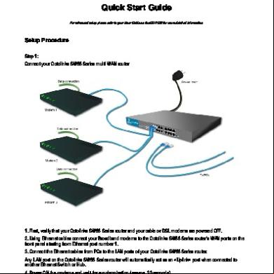
Syswan Octolinks Sw88 Multi Wan Router Quick Installation Guide 4s154b
December 2019 29
Router Vpn Dual Wan Cisco Rv082 2m2o5p
June 2022 0
Cisco Rv042g Dual Gigabit Wan Vpn Router 4f1s4n
February 2021 0More Documents from "Syswan Technologies, Inc." 146fy
Syswan Octolinks Sw88 Multi Wan Router Quick Installation Guide 4s154b
December 2019 29
Syswan Octolinks Sw88 Multi Wan Router Guide 6w4w20
December 2019 24
Syswan Duolinks Sw24 Series Dual Wan Router Guide 3z6y7
November 2019 25
Syswan Duolinks Sw24 Series Dual Wan Router Quick Installation Guide 27725r
January 2022 0
Altibox Automates Network Diagramming With Opnet Netmapper 5h5if
December 2021 0