Specification For External 3lpe 2n6o1m
This document was ed by and they confirmed that they have the permission to share it. If you are author or own the copyright of this book, please report to us by using this report form. Report 2z6p3t
Overview 5o1f4z
& View Specification For External 3lpe as PDF for free.
More details 6z3438
- Words: 8,524
- Pages: 25
Page 1 of 25
Nord Stream 2
Specification for External Three Layer Polyethylene Coating
Document Owner
Michael Frame
Review Manager
Klaus Schmidt
Approver
Trond Gjedrem
W-MA-ENG-GEN-SPE-800-ACC001EN-02
Rev.
Date
01 02
2015-11-04 2016-02-24
Description
Feb 26, 2016
Page 2 of 25
Table of Contents
1
2
3
4
5
SCOPE................................................................................................................................................5 1.1
Definitions ...............................................................................................................................5
1.2
Abbreviations...........................................................................................................................5
SPECIFICATIONS, CODES AND STANDARDS.....................................................................................5 2.1
General ...................................................................................................................................5
2.2
Codes, Standards and Regulations ...........................................................................................6
REQUIREMENTS.................................................................................................................................8 3.1
Operating environment and design temperature.........................................................................8
3.2
Composition of the coating system ............................................................................................9
Coating Materials ...............................................................................................................................9 4.1
Epoxy primer ...........................................................................................................................9
4.2
Adhesive .................................................................................................................................10
4.3
HDPE Layer.............................................................................................................................10
Storage of coating materials ..............................................................................................................11 5.1
6
7
Preservation of coating materials ..............................................................................................11
Cleaning and surface preparation before coating ..............................................................................11 6.1
Environmental conditions..........................................................................................................11
6.2
Preheating of pipes ..................................................................................................................12
6.3
Abrasive Cleaning....................................................................................................................12
3 Layer Coating...................................................................................................................................12 7.1
Coatings Materials ...................................................................................................................12
7.2
PE application methods............................................................................................................13
7.3
Line pipe, Buckle arrestors and transition pieces coating cut back...............................................14
8
Marking ..............................................................................................................................................15
9
Handling, Storage and Deliv ery of the coated pipes...........................................................................15 9.1
Pipe Storage ...........................................................................................................................15
9.2
Pipe Handling, Stacking ..........................................................................................................15
10 Local safety requirements and HSE requirements .............................................................................16
Specification for External Three Layer Polyethylene Coating
W-MA-ENG-GEN-SPE-800-ACC001EN-02
2016-02-24
Page 3 of 25
11 Defectiv e coating, coating repairs .....................................................................................................16 12 Quality Control and Inspection activ ities...........................................................................................17 12.1
Manufacturing Procedure Qualification Test...............................................................................17
12.1.1 12.2
Documentation for MPQT ....................................................................................................18
Qualification testing of coating ..................................................................................................18
12.2.1
Visual examination ..............................................................................................................18
12.2.2
FBE layer porosity ...............................................................................................................18
12.2.3
Coating thickness ................................................................................................................18
12.2.4
Degree of cure.....................................................................................................................18
12.2.5
Holiday Test........................................................................................................................19
12.2.6
Hot water soak test...............................................................................................................19
12.2.7
Quality requirements and inspection for MPQT and production ..............................................19
12.3
Reception of bare pipes............................................................................................................21
12.4
Reception of the coating materials.............................................................................................21
12.5
Pipe identification.....................................................................................................................21
12.6
Control of surface cleanliness....................................................................................................22
12.6.1
Visual inspection .................................................................................................................22
12.6.2
Check of surface roughness and coating ..............................................................................22
Table 12.6.2. Requirements for inspection of surface preparation and coating ...............................22 12.7
Quality Inspection during production .........................................................................................24
12.7.1
Tests and Test Frequencies.................................................................................................24
12.7.2
Visual inspection .................................................................................................................24
12.7.3
Hot water soak test...............................................................................................................24
12.8
Repair Control .........................................................................................................................24
12.9
Residual magnetism.................................................................................................................24
13 Documentation ...................................................................................................................................24 14 Load Out.............................................................................................................................................25
Specification for External Three Layer Polyethylene Coating
W-MA-ENG-GEN-SPE-800-ACC001EN-02
2016-02-24
Page 4 of 25
SPECIFICATION FOR EXTERNAL THREE LAYER POLYETHYLENE COATING
Document N° W-MA-ENG-GEN-SPE-800-ACC001EN
OLD Document N° N°. N-EN-PLM-SPE-000-EXTACCCO N°. N-EN-PIE-SPE-000-00000003
Specification for External Three Layer Polyethylene Coating
W-MA-ENG-GEN-SPE-800-ACC001EN-02
2016-02-24
Page 5 of 25
Specification for External Three-Layer Polyethylene Coating 1
SCOPE
This Specification defines the functional requirements for the external three-layer PE anti-corrosion coating system to be applied on the Nord Stream 2 Offshore Pipeline through the Baltic Sea. The pipes may also be coated with concrete coating prior to installation in order to provide sufficient negative buoyancy. Requirements for Internal Flow Coat and Concrete Weight Coating are covered in a separate specification. 1.1
Definitions
COMPANY
Nord Stream 2
CONTRACTOR
Coating Contractor, or their agents, who is responsible to COMPANY for the performance of the WORK as addressed within this specification.
SUPPLIER
Vendor or manufacturer for supply of material, equipment and services to the CONTRACTOR
1.2
Abbrev iations
APS
NS2 PE TBD
Applica ti on Procedure DSC Specif ication Exempli gratia (f or the Etc. sake of example) Enviro n m en t al Stress FBE Cracking Resistance High Density IR Poly ethy lene Health, Saf ety & ITP Env ironment Manufa ct u ri n g Procedure No. Qualifi cati o n Test Nord Stream 2 Of fshore Gas Pipeline Poly ethy lene Para To Be Decided PTS
Paragraph Pipe Tracking Sy stem
YS
Y ield Strength
Tensile Strength
3LPE
Three Lay er Poly ethylene UV
e.g. ESCR HDPE HSE MPQT
TS
Differe nti al Scanning Calorimetry Etcetera (and more) Fusion Bonded Epoxy Inf ra-Red Inspe cti o n and Testing Plan Number
Ultra Violet
2
SPECIFICATIONS, CODES AND STANDARDS
2.1
General
A certified quality system according to ISO 9001 shall be applied to assist compliance with the requirements of this document. A material and pipe tracking system has to be established according Company’s procedures and manual referenced in para 2.2. The Coating to be produced shall meet all requirements of DNV RP-F106. CONTRACTOR shall be responsible for the quality of materials, workmanship, and compliance with the requirements of all applicable legislative authorities, guidance notes and specifications.
Specification for External Three Layer Polyethylene Coating
W-MA-ENG-GEN-SPE-800-ACC001EN-02
2016-02-24
Page 6 of 25
2.2
Codes, Standards and Regulations
The latest issue of the following specifications, codes, standards and regulations shall form part of this specification. In the event of conflict between this specification and other specifications, data sheets, applicable codes or references, the specification W-MA-ENG-GEN-SPE-800-ACC001EN takes precedence. The Nord Stream Offshore Pipeline shall be designed to meet DNV OS-F101 Submarine Pipeline Systems (2013). The references listed below shall be considered by CONTRACTOR in their latest version and shall be regarded as an integral part of this Specification together with the contract documents. Compliance with DNV OS-F101, means compliance with DNV-RP-F106 which provides additional requirements, above industry standard document ISO 21809-1: 2011. This specification includes additional requirements specified by COMPANY.
COMPANY Specification/Procedure W-HS-HSE-GEN-PRO-800-LPCOATEN W-QY -QAC-GEN-SPE-800-PQSRCSEN
Title HSES Minimum Standards f or Line Pipe, Weight Coating and Logistics Project Quality Sy stem requirements for Contractors and Suppliers
W-MA-OFP-POF-SPE-800-INDBENEN W-MA-OFP-POF-SPE-800-LINEPIEN W-MA-ENG-GEN-SPE-800-FLC001EN W-LC-CWC-GEN-SPE-800-CWC001EN W-LC-CON-GEN-SPE-800-PTSFSPEN W-MA-OFP-POF-SPE-800-MEASUMEN
Specifi cati o n Specifi cati o n Specifi cati o n Specifi cati o n Pipe Tracki n g Measu re m en t
f or Bends Manufactured by induction Heating f or Line Pipe, (Inc. Buckle Arrestors and Transition Pieces) f or Internal Coating - Flow Coat f or Concrete Weight Coating - CWC Syste m Functi o n al Specifi cati o n of Residual Magnetism in Steel Line Pipe
DNV OS-F101
Submarine Pipeline Systems.
DNV-RP-F106
Factory applied external coatings for corrosion control
DIN EN ISO 306
Plastics-Determination of Vicat softening temperature of thermoplastics.
DIN EN ISO 527
Plastics-Determination of tensile properties
DIN EN ISO 8130-1
Coating powders – Part 1: Determination of particle size distribution by sieving
DIN EN ISO 8503-4
Preparation of steel substrates before application of paints and related products – Surface roughness characteristics of blastcleaned steel substrates – Part 4: Method for the calibration of ISO surface profile comparators and for the determination of surface profile; stylus instrument procedure
DIN 30670
Polyethylene coatings of steel pipes and fittings; requirements and testing
ISO 62
Plastics-Determination of water absorption
ISO 179
Plastics- Determination of Charpy impact properties
ISO 868
Plastics-Determination of indentation hardness by means of a durometer (Shore Hardness)
ISO 1133
Plastics-Determination of melt flow rate of thermoplastics.
ISO 1183
Plastics-Methods for determining the density and relative density (Specific Gravity) of plastics, excluding cellular plastics.
Specification for External Three Layer Polyethylene Coating
W-MA-ENG-GEN-SPE-800-ACC001EN-02
2016-02-24
Page 7 of 25
ISO 1304
Rubber-Carbon black. Determination of iodine-absorption number. Titrimetric method
ISO 1872
Plastics- Polyethylene (PE) moulding and extrusion materials – Part 2: Preparation of test specimens and determination of properties
ISO 2808
Paint and varnishes – Determination of film thickness
ISO 8501-1
Preparation of steel substrates before application of paints and related products. – Visual assessment of surface cleanliness. Part 1: Rust grades and preparation grades of uncoated steel substrates and of steel substrates after overall removal of previous coatings
ISO 8502-3
Preparation of steel substrate before application of paint and related products tests for the assessment of surface cleanliness – Part 3: Assessment of dust on steel surfaces prepared for painting (pressure-sensitive tape method)
ISO 8502-9
Preparation of steel substrate before application of paint and related products tests for the assessment of surface cleanliness – Part 9: Field method for the conductometric determination of water-soluble salts
ISO 8503-1
Preparation of steel substrate before application of paint and related products surface roughness characteristics of blast cleaned steel substrate
ISO 8503-4
Preparation of steel substrate before application of paint and related products surface roughness characteristics of blast cleaned steel substrate – Part 4: Method for the calibration of ISO surface profile comparators and for the determination of surface profile
ISO 9001
Quality Management Systems - Requirements
ISO 11124
Preparation of steel substrates before application of paints and related products – specification for metallic blast-cleaning abrasives
ISO 11127-6
Preparation of steel substrates before application of paints and related products – test methods for non-metallic blast-cleaning abrasives – Part 6: Determine of water-soluble contaminants by conductivity measurement
ISO 11357
Plastics – Differential scanning calorimetry (DSC) – Part 2: Determination of glass transition temperature
ISO 15512
Plastics – Determination of water content
ISO 21809-1
Petroleum and natural gas industries –External coating for buried or submerged pipelines in pipeline transportation systems – Part 1: Polyolefin coatings (3-layer PE and 3-layer PP)
ISO 21809-2
Petroleum and natural gas industries –External coating for buried or submerged pipelines in pipeline transportation systems – Part 2: Fusion-bonded epoxy coatings
ISO 11127-6
Preparation of steel substrates before application of paints and related products -- Test methods for non-metallic blast-cleaning abrasives -- Part 6: Determination of water-soluble contaminants by conductivity measurement
ASTM D 570
Water absorption of plastics
Specification for External Three Layer Polyethylene Coating
W-MA-ENG-GEN-SPE-800-ACC001EN-02
2016-02-24
Page 8 of 25
ASTM D638
Tensile properties of plastics
ASTM D1505
Flow rates of thermoplastics by extrusion plastometer
ASTM D1525
Vicat softening temperature of plastics
ASTM D 1693
Environmental stress-cracking of ethylene plastics.
ASTM D 2240
Rubber property – Durometer hardness
ASTM D 4060
Abrasion resistance of organic coatings by the Taber Abraser
ASTM D 4940
Standard Test Method for Conductimetric Analysis of Water Soluble Ionic Contamination of Blast Cleaning Abrasives
ASTM G8
Test for cathodic disbonding of pipeline coatings
ASTM G 14
Test for impact resistance of pipeline coatings (falling weight test)
ASTM G 42
Cathodic disbonding of pipeline coatings subjected to elevated or cyclic temperature
SSPC-AB-1
Mineral and Slag Abrasives
SSPC-AB-2
Cleanliness of Recycled Ferrous Metallic Abrasives
SSPC-AB-3
Ferrous Metallic Abrasive
3 3.1
REQUIREMENTS Operating env ironment and design temperature
The PE external anti-corrosion coating shall be able to withstand a maximum design temperature of 80°C, and a minimum design temperature of -40°C both in an offshore and onshore environment involving attack by chemical agents and/or of microbiological type. Storage conditions of coated pipes: coating shall be able to withstand a minimum temperature of -40°C and a maximum temperature of +80°C. Design life of the 48” O.D. pipelines is 50 years and shall include several (3 or 4) wall thicknesses. Line pipes for offshore use have a minimum design temperature equal to -10°C, maximum design temperature equal to +40°C. Note: Some line pipe quantities intended for above ground use at landfalls may be ordered without coating and with wider design temperature range (typically these pipes shall have minimum design temperature equal to -38°C and maximum design temperature of +60°C). The design pressures range from 177.5 barg to 220 barg. CONTRACTOR shall ensure that his application procedures shall have no detrimental effect on the internal flow coating which may have been applied by others, including the introduction of contamination/material deposits from the 3LPE process onto the painted surface. Reference is made to COMPANY specification W-MA-ENG-GEN-800-FLC001EN. The surface roughness, the mechanical properties and the integrity of the internal coating shall not be negatively affected by the external coating process.
Specification for External Three Layer Polyethylene Coating
W-MA-ENG-GEN-SPE-800-ACC001EN-02
2016-02-24
Page 9 of 25
3.2
Com position of the coating system
The pipe external coating shall consist of: -
One layer of fusion bonded epoxy; thickness shall be minimum 0.150 mm.
-
One layer of adhesive; thickness shall be minimum 0.200 mm.
-
One layer of HDPE base with additives.
-
One layer of PE Powder (Rough Surface Finished, minimum particle size 0.5 mm).
-
The overall coating thickness, excluding possible sinter powder used for increasing the surface roughness, obtained by adding the thickness of the individual layers shall be minimum 4.2 mm and maximum average of 7.2 mm. The minimum thickness may be reduced by a maximum of 10% on top of the longitudinal weld seam. (Minimum coating thickness is 3.8 mm on top of the weld). Minimum and average thickness values shall be measured in accordance with the clause 12.2.3 of this document.
4
Coating Materials
The materials shall be fully compatible with each other for use in a Three-Layer Polyethylene coating system. The adhesive copolymer and the polyethylene top coat shall preferably be produced by the same Manufacturer. Contractor shall propose a Three Layer PE Coating System in compliance with the requirements of this specification and shall have a proven track record on similar projects. 4.1
Epoxy primer
The epoxy resins to be used shall: a) b)
be completely compatible with the adhesive shall be in compliance with Table 1
Table 1 — Requirements for the epoxy material Properties
Unit
Test Method
Moisture content
% by mass
Annex K of ISO 21809-1
d 0, 6
Minimum glass transition temperature (Tg2) (DSC Analy sis) Gel time at 205°C +/-3°C.
°C
t 95, and as per manuf acturer specification.
Density
g/l
Annex D of ISO 21809-1 Annex J of ISO 21809-1 Annex N of ISO 21809-1
%
Requirements
± 20%. Within per manuf acturer’s specification As per manuf acturer’s specification r 0,05
Note: DSC Analysis, Polymerization condition in accordance of Manufacturer Specification.
Specification for External Three Layer Polyethylene Coating
W-MA-ENG-GEN-SPE-800-ACC001EN-02
2016-02-24
Page 10 of 25
4.2
Adhesiv e
The adhesive (polyethylene compatible grafted type) shall be in compliance with Table 2 Table 2 — Requirements for the adhesiv e material (grafted adhesive in pellet) Properties
Unit
Test Method
Requirements
Elongation at break at 23 °C +/- 2 °C (a)
%
ISO 527-2 or ISO 527-3
t 600
Tensile y ield strength at 23°C +/-2 °C
Mpa
ISO 527-2 or ISO 527-3
t8
Vicat sof tening temperature A/50 (9.8N)
°C
ISO 306
t 85
Water content
%
ISO 15512
d 0,1
(a) 2 mm thick compression moulded sheet, test specimen ty pe according to ISO 527-3, strained at 50 mm/min
4.3
HDPE Layer
The PE compound shall: a) be able to withstand the maximum design temperature (80°C) and pipes storage conditions of the pipeline and be dyed by the CONTRACTOR with 2-3% of carbon black with iodine absorption number always over 110 (ISO 1304), stabilized with additives to withstand oxygen action and the application and service temperatures. Additives used shall not float to the surface of the coating while it is being applied. b) be in compliance with Table 3.
Table 3 — Minimum requirements for PE top layer Properties
Unit
Melt f low index/rate
g/10mn
ISO 1133
Manuf acturer data sheet
Density of the base resin
g/cm 3
ISO 1183 (all parties)
t 0.930
%
ISO 527-2 or ISO 527-3
t 600
Table 1 -Tensile Y ield strength at 23 °C +/-2°C **
Mpa
ISO 527-2 or ISO 527-3
t 15
Vicat sof tening temperature A/50 (9.8N)
°C
ISO 306
t 110
Water content
%
ISO 15512
d 0,05
Hardness Shore D
Unit
ISO 868
t 55
ESCR (50 °C, F50, Cond. A or B, 10% Igepal CO 630)
h
Oxidation induction time (intercept in the tangent method)
min
Elongation at break at 23°C +/-2°C **
Specification for External Three Layer Polyethylene Coating
Test Method
ASTM D-1693
ISO 11357
Requirements
t 1000 t 30 at 210 ° C
W-MA-ENG-GEN-SPE-800-ACC001EN-02
2016-02-24
Page 11 of 25
Resistance to abrasion UV Resistance and thermal ageing
mg/1000 turns %
ASTM D 4060 Annex G ISO 21809-1
”10 'MFR d 35
** 2 mm thick compression moulded sheet, specimen ISO 1872-2, strained at 50 mm/min
5
Storage of coating m aterials
5.1
Preserv ation of coating materials
Materials that shall be used for coating shall be stored as follows in the CONTRACTOR’s facilities: All cleaning and coating materials shall be stored in such a manner that they are not detrimentally affected by climatic or other injurious conditions and according to the supplier’s recommendations. The containers holding liquid products shall be kept hermetically sealed, and be protected from sun rays and stored at a proper distance from heat sources and from those areas where free flames are used. The containers shall not be in direct with the ground. Solid products shall be kept in sheltered areas with controlled temperature and humidity, in accordance of the supplier’s recommendations. Products supplied packaged shall be kept in their packing until they are used; any handling shall be carried out taking care not to damage these packages. Packaged materials shall not be placed nor stored on wet or damp surfaces or environments, nor in places that can be flooded or are near to possible sources of fire. All products that become altered for any reason shall be removed from the manufacturing areas. Raw materials shall be used in a manner First In / First Out.
6
Cleaning and surface preparation before coating
Before pipes are cleaned, all pipes shall be carefully visually inspected to check metal surfaces for corrosion and any presence of oil, grease or other foreign substances, in order to be able to choose the most suitable cleaning process. Pre-treatments shall be performed, if needed, in accordance to the provisions of ISO 8501-1. All pipes shall be externally washed by high pressure fresh water at the plant entry point. The minimum water pressure shall be hundred (100) bars. The washing operation shall be carried whilst the pipe is rotating. The total external pipe surface shall be cleaned. The cleaning method shall be tested and documented as report as part of the MPQT. 6.1
Env ironmental conditions
CONTRACTOR shall check that the pipe surface is completely dry before blast cleaning. The pipe temperature shall be at least 3°C above the dew point immediately prior to abrasive blast cleaning.
Specification for External Three Layer Polyethylene Coating
W-MA-ENG-GEN-SPE-800-ACC001EN-02
2016-02-24
Page 12 of 25
6.2
Preheating of pipes
The equipment used for preheating the pipes shall be approved by COMPANY. If CONTRACTOR uses open flames in direct with the pipe surface, the surface shall be kept in motion in respect to the flame at a minimum rate of 10 mm/sec, along a helically winding path. The flame shall also be adjusted in its combustion ratio so that no soot or moisture is deposited on the metal. The preheat temperature shall be kept between 35°C and 80°C; it shall be checked at least three times for every work shift (at the start, middle, and end) and whenever stoppages occur in the production line. Preheat temperature shall be checked using thermometers or similar COMPANY approved devices. All temperature measurements shall be recorded on the production record. 6.3
Abrasiv e Cleaning
The grit used in the coating plant shall be in accordance with the requirements of ISO 11124. The abrasives shall be maintained clean, dry and free from contaminants in accordance to SSPC-AB 1, SSPC-AB 2 and SSPC-AB 3 so as not to contaminate the substrate. The use of shot (round) abrasives is not allowed. Pipe surfaces shall be cleaned to a degree corresponding as a minimum to Sa 2 1/2 of ISO 8501-1, i.e. white metal finish. After completion of the blasting operation the steel surface shall be thoroughly checked. Any slivers, swabs, burns, laminations and gouges shall be removed by grinding. The remaining wall thickness shall comply with minimum requirements of Document No. W-MA-OFP-POF-SPE-800-LINEPIEN Specification for Line Pipe. The maximum allowable area of grinding shall be 10 cm 2 per 1m pipe length. The average surface roughness Rz (cut off 2.5) shall be between 50 and 90 microns, measured according to ISO 8503-4. Soluble salts on the steel surface shall be checked after water washing, before and after blast cleaning and should preferably be performed on the cut back area. Salt contaminations on the surface shall be measured by a Soluble Salt Detector, SCM 400 or equivalent, measuring conductivity. Requirements: Maximum 1μg/cm². Steel pre-treatment using chromate solution is required, and shall be part of the MPQT and shall follow the recommendations of the SUPPLIER. Time lapse between blasting to coating application shall be limited as follows: Relative humidity (R.H) RH > 80% 70% < RH < 80% RH < 70%
7
3 Layer Coating
7.1
Coatings Materials
Max elapsed time 1.5 hours 2 hours 3 hours
The coating material (batch certificate) shall be supplied in accordance with DNV-RP-F106.
Specification for External Three Layer Polyethylene Coating
W-MA-ENG-GEN-SPE-800-ACC001EN-02
2016-02-24
Page 13 of 25
7.2
PE application methods
Coating materials shall be applied according to the Manufacturer’s recommendations and following the CONTRACTOR’s application procedure approved by COMPANY. Note: Use of recycled FBE material is not allowed. It is not allowed to stop and restart the coating application sequence on any pipe. If stoppage cannot be avoided, the coating already applied shall be stripped and the pipe shall be sent back to the process starting point (blast cleaning). The maximum temperature of the steel shall be limited to 225°C. Unless the CONTRACTOR can prove that the Internal Flow Coating and steel properties define in specifications W-MA-ENG-GEN-800-FLC001EN and W-MA-OFP-POF-SPE-800-LINEPIEN respectively are not affected by the higher steel temperature. Constant measurement of pipe temperature shall be taken by automatic pyrometers and recorded before and after FBE application. Line speed shall also be recorded. PE application shall result in a homogeneous and solid coating, showing good adhesion, no wrinkles, no cavities, no air bubbles and no air entrapment along the weld seam; this applies in particular to where weld beads protrude from the rest of the pipe surface. The surface of the PE coated pipes shall be specially treated in order to obtain a rough surface which provides high level of shear resistance between PE and Concrete Coating. The rough coat shall be applied in such as manner as to provide a uniform finished, securely adhered to 100% of the 3LPE coated surface. CONTRACTOR and Weight Coating CONTRACTOR shall prove that this surface is sufficient by testing pipes which have received a concrete coating layer on top of the PE layer, see MPQT requirements, section 12.1 Forced cooling shall result in no damage or deterioration of the PE coating. Note: As part of the MPQT, verification need to be done for steel properties, in case of more than one stripping is necessary to be done on the same pipe. In case one pipe is subject of stripping more than once, the supplier needs to prove the steel properties are not adversely affected and the pipe properties for YS + TS are maintained however the YS/TS ratio maximum shall not exceed 0.94, (in transverse and longitudinal direction). For that, simulation of stripping operation on bare pipe needs to be done according to the following process: 1) 2) 3) 4) 5)
Pipe heating at the temperature requested for coating application (max 225°C). Pipe water cooling until ambient temperature. Pipe heating at temperature necessary for stripping. Pipe water cooling until ambient temperature. Realization of samples for the verification of the Yield Strength (YS) and Tensile Strength (TS).
This operation cycle of coating and stripping simulation and Yield Strength, Tensile Strength testing needs to be repeated two times on the same pipe (total three cycles). After this verification is done and acceptable results are obtained, the following requirement shall apply: In case, pipe(s) need to be stripped more than two times, the relevant pipe(s) after the second stripping need to be subjected to natural rust surfaces before re-blasting and coating.
Specification for External Three Layer Polyethylene Coating
W-MA-ENG-GEN-SPE-800-ACC001EN-02
2016-02-24
Page 14 of 25
7.3
Line pipe, Buckle arrestors and transition pieces coating cut back
External coating shall be removed (cut back) from the pipe ends with a tolerance of +/-10 mm over a length to be specified by COMPANY at later stage. The exact length and tolerance depends on selected pipe lay contractor and has to be confirmed by COMPANY no later than six (6) weeks before Manufacturing Procedure Qualification Test. Cut back includes full removal of both PE layer and of the adhesive layer, while the epoxy layer shall be left to a distance of 50 ± 20 mm from PE bevel. No damage of the protruding epoxy primer layer shall be accepted over a distance of minimum 30 mm to the base of the PE bevel. In case of damage in that area the cut back length of the PE- and adhesive layers shall be increased to reach a 30 mm wide undamaged primer layer. In case the total cut back length exceeds the specified maximum value the pipe shall be reduced in length by re-beveling. The re-finished pipe end shall comply with the requirements of W-MA-OFP-POF-SPE-800-LINEPIEN.
30mm
Damages of less than 4 cm² are acceptable on the protruding epoxy primer layer located outside the above mentioned 30 mm wide undamaged primer zone. The maximum number of damagesis two (2) per pipe end. A series of four (4) sequential pipes (during production) with damages shall immediately requires corrective action at the end finishing station. Damages located after the 30 mm wide undamaged zone, as described above, shall be repaired according to a procedure proposed and accepted at MPQT by the COMPANY. The PE removal straight to the 50 mm of the epoxy protruding as well as the angle of the PE of ” 20 degrees shall be carried out by a tool type knife, wire brushes are not authorized. Local spots of residual adhesive layer, or larger areas with thin adhesive layer (Epoxy has to shine through) in the 50 mm protruding epoxy layer are acceptable. The cut back end shall be tapered to an angle of ”20 degrees to the epoxy primer layer. The bare pipe ends (including root face and bevels) shall be properly cleaned to bright steel and shall be free of any fabrication residuals. Pipe ends shall not to be protected by any kind of painting (varnish or equivalent). Hard Stamp shall be varnish (durable protection) and a white paint mark close to the hard stamp shall be applied on the bevel to easily locate the hard stamp.
Specification for External Three Layer Polyethylene Coating
W-MA-ENG-GEN-SPE-800-ACC001EN-02
2016-02-24
Page 15 of 25
Note: For Buckle Arrestors and Transition Pieces, cut back length and tolerance depends on selected pipe lay contractor and has to be confirmed by COMPANY. Schematic shall be provided by the COMPANY. Buckle arrestors and transition pieces shall be manufactured from standard pipe lengths with machining taking place after 3LPE application.
8
Marking
CONTRACTOR shall assure that neither the hard stamped markings on pipe ends (bevels), the bar codes nor the internal stencil marking are damaged during the coating and handling process. Marking shall be performed at line pipe mill and internal coating facilities in accordance with W-MAOFP-POF-SPE-800-LINEPIEN and W-MA-ENG-GEN-SPE-800-FLC001EN respectively.
9
Handling, Storage and Delivery of the coated pipes
9.1
Pipe Storage
Pipe storage areas within the CONTRACTOR’s facilities shall meet the following requirements:
9.2
-
Storage area shall be at least thirty (30) meters distance from any type of electrical power line, the distance being measured from the vertical projection on the ground of the nearest conductor.
-
Shall be free or be freed before use from all kinds of plant life; the same applies to a surrounding area of a width sufficient to keep fires from propagating to the pipe stacks.
-
Shall be free or freed before use from protruding stones and foreign matter.
-
Shall be level on a horizontal plane, in order to allow uniform loading of the s and ensure stack stability.
-
Flat wooden s shall be positioned on the ground. The outside s shall be at least 0.5 meter distance from the pipe end.
-
Shall have sufficient load bearing capacity, in order that no occurs between pipes and ground soil shall be at least twenty (20) cm. Should the distance between the ground and the bottom of the first layer be less than 20cm mentioned above, restacking should be required by the Company.
-
s shall be of a size and number sufficient for avoiding permanent deformations, through proper load distribution.
-
Shall never be directly exposed to salt water spray.
-
Shall be stacked in an area that is self-draining and / or guarded against localized flooding.
Pipe Handling, Stacking
All stacking operations shall be performed using lifting equipment (such as cranes, overhead or other, lift trucks) with adequate slings equipped of hooks protected or vacuum systems. Hooks for lifting pipes from their ends shall be provided with a rubber or copper sheathing in order to avoid damaging the pipe bevels and coating.
Specification for External Three Layer Polyethylene Coating
W-MA-ENG-GEN-SPE-800-ACC001EN-02
2016-02-24
Page 16 of 25
Handling operations and equipment shall all strictly comply with the applicable safety regulations and laws Suspended pipes shall be kept from swiveling around, either by the type of lifting device selected or by the addition side guide ropes attached to the lifting equipment. All personnel involved in the handling operations shall be adequately trained. When handled, pipes shall be kept from striking or scraping against other bodies or pipes; positioning of the pipes on those already stacked shall be carried out using utmost care. Slings equipped with hooks shall also neither strike nor scrape the pipes. Handling procedure shall have to be submitted and approved by COMPANY. Stack height Calculations shall be submitted to COMPANY for approval. Pipe Surface temperatures of the coating can reach - 40°C in winter and + 80°C in summer Careful visual inspection shall be performed during transportation, and all pipes showing damage and/or surface defects shall be properly repaired (see § 11). Bevels with depth damages over one (1) mm caused by handling operations shall be re-beveled. Damages to pipes caused during coating process shall not be accepted and the cause for such damages shall be rectified prior to production start.
10
Local safety requirements and HSE requirements
It is the duty of CONTRACTOR to observe the local regulations on safety and health applicable to his premises. Special consideration shall be given to the following: a)
The abrasives selected for blast cleaning shall not be harmful to operators’ health.
b)
The material storerooms shall be appropriately ventilated and complying with applicable law provisions on safety and fire prevention.
11
Defective coating, coating repairs
Defects caused during coating process are not acceptable and pipes have to be rejected. Pipes have to be recoated after stripping. Repairs are only allowed on coating damages caused by handling, transport and destructive coating tests. CONTRACTOR shall forward a coating repair procedure which considers the following repair limitations: A.
Maximum damaged coating area shall not exceed 100 cm 2.
B.
Regardless of the area, not more than three (3) repairs may be performed on each individual pipe; no repair shall be allowed in the first 400 mm of each end of the pipes.
C.
Complete removal of the coating shall be required when the above limits are exceeded.
Specification for External Three Layer Polyethylene Coating
W-MA-ENG-GEN-SPE-800-ACC001EN-02
2016-02-24
Page 17 of 25
CONTRACTOR shall propose a repair procedure, including materials which shall be qualified and approved by COMPANY before use. The proposal shall specify the material characteristics, as well as application and test / inspection method. The area to be repaired shall be adequately prepared by removing the damaged coating until sound coating is reached, and the edges smoothed down to the steel or FBE surface to ensure an even transition between the top of the repair and the bottom. Maximum temperature during Stripping / Recoating & Repair shall not exceed 225°C.
12
Quality Control and Inspection activities
12.1
Manufacturing Procedure Qualification Test
CONTRACTOR shall prepare a test program and submit this for approval to the COMPANY. This MPQT shall be performed under the surveillance of Company. The CONTRACTOR shall require from SUPPLIER that all coatings materials are qualified in accordance with the requirements of this specification (Para 4.1 to 4.3) and DNV-RP-F106. Historical Data can be accepted if this data is not more than two (2) years old and the tests have been executed by an independent and accredited test laboratory. At least twelve (12) weeks before coating production start, fifteen (15) sample pipes shall be coated continuously (in one sequence run) without break, by CONTRACTOR. These fifteen (15) pipes shall be specially inspected and tested and shall act as the Manufacturing Procedure Qualification Test (MPQT). Where possible, the MPQT should be performed on the same pipe (heats) as used for the line pipe (steel) MPQT, including the four MPQT pipes which have been subject to mechanical testing during line pipe MPQT. They shall all be prepared to a surface cleanliness and roughness complying with this Specification. The qualification shall be repeated should any of the following changes be made after MPQT: -
Raw material composition. Production process and parameters which influence the material processing behavior. Line speed defined during MPQT (tolerance ± 5%). Change of wall thickness (unless approved otherwise by COMPANY) New production line. Production facility.
Coating system applied during MPQT shall be specified in the MPS document. Coating repair shall also be performed during the MPQT in accordance with DNV-RP-F106, Sec.6.4.11. Testing on repairs shall be shown in CONTRACTOR APS approved by COMPANY. One pipe shall be coated with 1/3 of the length with a full 3-Layer PE Coating, 1/3 of the length only with adhesive and epoxy primer layer and 1/3 of the pipe length with only epoxy primer. This pipe shall be subject to full visual inspection, and all non-destructive and destructive coating tests as per acceptance criteria as specified in this Specification. The fourteen (14) remaining pipes shall meet all MPQT criteria’s. Twelve (12) fully coated pipes (three layers) shall thereafter be sent to a concrete coating yard for concrete coating and testing as per concrete coating specification: W-LC-CWC-GEN-SPE-800CWC001EN.
Specification for External Three Layer Polyethylene Coating
W-MA-ENG-GEN-SPE-800-ACC001EN-02
2016-02-24
Page 18 of 25
12.1.1 Documentation for MPQT In line with COMPANY approved schedule, CONTRACTOR shall supply the following documents for COMPANY approval: -
Coating application procedure specification (APS) in accordance with DNV-RP-F106. Inspection and test plan (ITP) in accordance with DNV-RP-F106. Where possible, all information shall be included under one manufacturing and inspection document.
All manufacturing and inspection steps required for the process shall be included. Testing and inspection shall be performed in a systematic manner to ensure repeatability of testing. MPQT shall be documented in a separate report and approved by COMPANY prior to start of mass production and shall meet the requirements of DNV-RP-F106, section 6.4. CONTRACTOR shall prepare a Daily Log Format in accordance with DNV-RP-F106 for COMPANY approval prior to the start of production. During production the daily log shall be updated on a daily basis and be available for COMPANY review at any time throughout production. 12.2
Qualification testing of coating
12.2.1 Visual examination All PE coated pipes shall be subjected to visual inspection. The coating shall not present any type of defect, such as: air bubbles, air entrapment located at weld seam, wrinkles, cuts, bulging or heaping of material, lack of fusion of the sides for laterally extruded coating, etc. The regularity of the PE layer roughness is inspected by comparison with a sample taken on MPQT pipe. 12.2.2 FBE layer porosity The coating integrity of each test pipe shall be examined by viewing the cross section of the coating thickness. The FBE-Layer shall be examined under x40 magnification. Porosity and voids in the corrosion coating shall follow the reference of ISO standard 21809.2. 12.2.3 Coating thickness Coating thickness shall be checked by means of an electronic depth measuring device in accordance with ISO 2808 method No. 7 and ISO 21809-1, Annex A. Checking by means of a pit depth gauge shall not be permitted. Coating thickness checks shall be made on each pipe. The thickness inspection shall consist of an electronic measurement of the coating thickness at twelve (12) locations around the pipes circumference over the full coated pipe length. Six (6) measurements shall be made on the weld over the full pipe length in addition to those specified above. 12.2.4 Degree of cure The thermal properties of the cured FBE layer shall be measured by the use of Differential Scanning Calorimetric (DSC) in accordance with ISO Standard 21809.1 Annex D. ǻTg shall be within ± 3°C. The results of all of these measurements are to be included in the MPQT report.
Specification for External Three Layer Polyethylene Coating
W-MA-ENG-GEN-SPE-800-ACC001EN-02
2016-02-24
Page 19 of 25
12.2.5 Holiday Test The holiday detector shall be operated according to ISO Standard 21809.1. Annex B. The voltage shall be set at 25 KV. 12.2.6 Hot water soak test During coating qualification, at the beginning of production, at each start up and at each FBE batch changes CONTRACTOR shall provide minimum three (3) samples coated with FBE primer layer only for hot water soak tests that certify long term bonding properties of the coating. The test section shall be subjected to water immersion testing at 80ºC ± 3ºC (COMPANY shall consider alternative methods that do not require pipe cutting). The coating shall show no loss of adhesion after 48 hours, tested by cross cut test. A detailed test and evaluation-procedure for this test shall be prepared by CONTRACTOR and shall be approved by COMPANY. In addition, the full 3LPE system shall be tested in accordance with ISO 21809-1, Annex M. Note: COMPANY reserves the right to have the results of the certified tests confirmed through testing at other laboratories. 12.2.7 Quality requirements and inspection for MPQT and production Table 12.2.7 Item / Property
Coating Qualification Testing (MPQT) and Production Control Test Method Acceptance criteria Frequency MPQT Production
Epoxy Layer
ISO 2808 method 7. And Para 12.2.3 ISO 21809.1 Annex D. And Para 12.2.4
150 μm minimum/ maximum agreed at MPQT Tg 2 – Tg ǻWJ ǻWJ± 3ºC
1 pipe
Hot water soak test
Para 12.2.6
No loss of adhesion
1 pipe
FBE Layer porosity
ISO 21809-2 And Para 12.2.2
No greater than level show in ISO 21809-2
1 pipe
FBE Layer dry adhesion
ISO 21809-2 Annex A.4
Rating 2
1 pipe
200 μm minimum/ maximum agreed at MPQT
1 pipe
Thickness Degree of cure
Adhesiv e Layer Thickness Full Layer Thickness
Para 12.2.3 ISO 2808 method 7. And Para 12.2.3
Specification for External Three Layer Polyethylene Coating
4.2 mm minimum Average 7.2 mm maxi. (-10% maxi on the weld seam, 3.8 mm).
1 pipe
all pipes
Every day at the beginning of the shift and each start up Every day at the beginning of the shift and each start up At the beginning of production, each start up and each changes of FBE batch At the beginning of production, each start up and each changes of FBE batch At the beginning of production, each start up and each changes of FBE batch Every day at the beginning of the shift and each start up On the first 5 pipes at the beginning of each shift and after every 10 th pipes
W-MA-ENG-GEN-SPE-800-ACC001EN-02
2016-02-24
Page 20 of 25
Visual Inspection
/
Holiday test
ISO 21809-1 And Para 12.2.5
Sound and continuous each pipe coating 25 KV. No holiday
each pipe all pipes
each pipe each pipe First pipe and start up/lead pipe, then one per shift both pipe ends at 20°C and 80°C
Adhesion (peel strength)
ISO 21809.1 Annex C (Figure C2)
Min 150 N/cm at 20°C Min 40 N/cm at 80°C In each case tolerance ± 2°C
Impact resistance
ISO 21809-1 Annex E
10 impacts at 7 J/mm at 23°C ± 2°C 7 J/mm at -40°C ± 2°C
3 pipes 1 pipe
> 15 MPa. 23°C ± 2°C
once
once per PE batch
once
once per PE batch
once
once per PE batch
once
each start up
Tensile strength (a) Elongation at break Indentation In process degradation and UV resistance
-40°C test on pipe samples ISO 527-2 or ISO 527-3 ISO 527-2 or ISO 527-3 ISO 21809-1 Annex F ISO 1133 And ISO 21809-1 Annex G
After extrusion • 400 % 23 °C ± 2°C 0.2 mm at 23 ± 2°C 0.4 mm at 80 ± 2°C ǻ0)5” (comparison between virgin granulate and after extrusion of the same batch) 24 hours@65°C, -3.5V 28 days@23°C, -1.5V 28 days@80°C, -1.5V Radius disbondment: < 7mm T° 23 and 65°C < 15 mm for T° 80°C
once per PE batch at 23°C ± 2°C
1 pipe per day at 65°C.
Cathodic disbonding (Temperature tolerances ± 2°C) Initial hole 6 mm.
ISO 21809-1 Annex H
Hot water immersion test
ISO 21809-1 Annex M
Average ” 2mm, 0D[LPXP” 3mm disbonding
1 pipe
Residual magnetism
COMPANY Specification W-MA-OFP-POFSPE-800MEASUMEN
20 Gauss average. 25 Gauss maximum
all pipes ends
1 pipe every 10 pipes at both ends. 4 measurement at each pipe end.
PE Powder. Rough surface for Final Layer.
Para 12.2.1
all pipes
all pipes
100% coverage of PE powder. Test pieces shall be agreed at MPQT for production quality control comparison
2 pipes At all temp At the beginning of production, each start up and each changes of FBE batch
Note: Due to prevailing ambient conditions, (greater than 23°C) Contractor may propose a higher test temperature when performing the adhesion & impact strength tests, as long as the acceptance criteria in this specification is met .
Specification for External Three Layer Polyethylene Coating
W-MA-ENG-GEN-SPE-800-ACC001EN-02
2016-02-24
Page 21 of 25
Requirements for inspection of Surface preparation and coating as per table 12.6.2 A “START UP” is defined as a modification of production parameters recorded during the MPQT or a stop of the coating line of more than 24 hours. All MPQT production parameters used, based on manufacturer requirement and tolerances, shall be recorded during qualification tests to ensure they are reproduced during the production phase. During production, should a change request of agreed parameters exceed the recommendations of manufacturer tolerancesand / or line speed above or below 5% of the actual speed qualified defined during MPQT, a new MPQT shall be performed. COMPANY shall define what production parameters shall be recorded with CONTRACTOR to confirm that MPQT quality is replicated in production. 12.3
Reception of bare pipes
Upon receiving the pipes to be coated, CONTRACTOR shall first at once that the pipes are not damaged and that there are no apparent defects. If damages such as dents, cuts or scratches are found on the bevel, these damages shall be recorded without fail in the shipping documents, making reference to the serial number of the pipes concerned. Damaged or defective non-conforming pipes shall be appropriately segregated (quarantined). CONTRACTOR shall provide a written report for submission to COMPANY that is entitled to reject damaged pipes. 12.4
Reception of the coating materials
All materials that shall be used for pipe coating shall be properly checked upon their delivery to the coating facilities, in order to that their containers are well preserved and to segregate immediately any material that does not comply with the requirements of this Specification. COMPANY may have samples of the delivered materials taken and analyzed elsewhere. The packaging / container markings shall also be checked, as well as the accompanying documents and shall include material certificates showing results of tests performed by the Manufacturer on the coating products. 12.5
Pipe identification
Before starting any work, CONTRACTOR shall be in possession of the Packing List of the pipes to be coated. If the Packing List is not yet available, CONTRACTOR shall request and obtain it before starting work. CONTRACTOR shall compare pipes serial numbers and these shall be matched with the ones listed, identifying all inconsistencies. When these cannot be solved (e.g. packing list without any such serial no. and showing no pipe of such length) a written report shall be submitted to COMPANY. CONTRACTOR shall take the pipes serial numbers and record them, and enter these data into the Pipe Tracking System of COMPANY. If pipes have not yet been internally coated and stencil marked inside, CONTRACTOR shall write pipe numbers with indelible paint on the pipe inside surface before starting work on the pipes.
Specification for External Three Layer Polyethylene Coating
W-MA-ENG-GEN-SPE-800-ACC001EN-02
2016-02-24
Page 22 of 25
Note: Internal coating (flow-coating) shall be completed before any external anti-corrosion coating is applied, except for special pipes requested by COMPANY . The serial number shall follow the pipe in all production stages and appear in the pipe final marking. It shall be recorded on all production documents and on the quality control record. All pipes shall be traceable to the coating material batch Number. Note: There shall be no hard-stamping of pipe steel surfaces (only exception is the pipe number hard-stamp on pipe (end) bevel, (see Specification for Line Pipe). 12.6
Control of surface cleanliness
After blast cleaning and before the primer is applied the pipe shall be subjected to the following checks: 12.6.1 Visual inspection All the blast cleaned pipes shall be subject to a visual inspection. CONTRACTOR shall assign properly qualified personnel to perform this inspection. In addition to ing that the surface cleanliness grade is as required, CONTRACTOR shall check that blast cleaning has not revealed surface defects such as slivers, scale, cuts, dents and pitting. All surface defects of a limited size (slivers, light pitting) shall be removed by light grinding. After grinding the remaining wall thickness shall (be measured and) comply with the minimum wall thickness tolerance requirements in the Line Pipe Specification. If the area to be ground exceeds 10 cm 2, CONTRACTOR shall re-blast the area. Dust test as per ISO 8502-3 shall be carried out during production, dust quality rating of 2 or better. Test frequency is every hour as long as results are acceptable, otherwise every pipe shall be dust tested. If defects such as scale, deep pitting and dents are found, CONTRACTOR shall segregate (quarantine) the pipe, marking clearly the defect area(s). These defective pipes shall be checked by COMPANY before any decision whether to use or scrap is made. 12.6.2 Check of surface roughness and coating At the start, and then every work hour the pipes surface roughness shall be checked in accordance with the provisions of ISO 8503. The roughness values measured shall be recorded on the relevant production certificate. Table 12.6.2. Requirements for inspection of surface preparation and coating
Properties Surf ace condition bef ore blasting
Unit /
Test Method Visual Inspection
Specification for External Three Layer Polyethylene Coating
Requirements f ree of contaminations and no steel def ect
Frequency during MPQT each pipe
W-MA-ENG-GEN-SPE-800-ACC001EN-02
Frequency during Production each pipe
2016-02-24
Page 23 of 25
Env ironnemental conditions
/
Pipe temperature bef ore blasting
°C
Size, shape and properties of abrasiv e
Water soluble contamination of abrasiv es
Soluble salt before blasting
Soluble salt after blasting
Surf ace roughness of blasted surf ace Rz
Visual inspection of blasted surf ace
/
μS/cm
μg/cm2
Calculation
as determined at time of measurement
once
ev ery 4 h
Thermocouple
Minimum 3°C abov e the dew point. (Minimum ambient temperature 5°C)
once
ev ery 4 h
Visual
Certif icate conf ormity
And ISO 11124
once
1 / day
(all metallic part)
And Compliance to manuf acturing / working procedures
ASTM D 4940
Conductiv ity max. 60
once
1 / shif t
each pipe
5 f irst pipes (beginning of the shif t) 1 pipe in the shif t
ISO 8502-9 and ISO 11127-6
ISO 8502-9 μg/cm2
μm
/
and ISO 11127-6
Salt content (NaCl) max. 1μg / cm2
Salt content (NaCl) max. 1μg / cm2
each pipe
5 f irst pipes (beginning of the shif t) 1 pipe in the shif t
ISO 8503-4
50 to 90 μm
5 pipes
At beginning of the shif t and af ter ev ery hour. At each pipe end.
ISO 8501-1
Grade Sa 2 1/2
each pipe
each pipe
5 pipes
ev ery 1 h
Max. class 2 Presence of dust af ter dust remov al
/
ISO 8502-3
d 2 f or the size and d 2 f or the quantity
Visual Inspection of pipe prior to introduction to the coating line Coating Line Speed Temperature control bef ore and af ter epoxy application and prior adhesiv e application
/
Visual
No steel def ect,
each pipe
each pipe
minutes
CONTRACTOR APS
Variation f rom MPQT +/- 5%
Minimum once
Minimum ev ery 0.5 hour
Max: 225°C
Continuously monitored, recorded f or each pipe
Continuously monitored, recorded minimum ev ery 0.5 hour
°C
Py rometer
Specification for External Three Layer Polyethylene Coating
W-MA-ENG-GEN-SPE-800-ACC001EN-02
2016-02-24
Page 24 of 25
Temperature of extruded adhesiv e and poly olef in
12.7
°C
Py rometer
Compliance to material supplier(s)
once
Ev ery 1 h
Quality Inspection during production
Production parameters shall be recorded (minimum every hour). Inspection and Testing Plan and daily log according to DNV-RP-F106. 12.7.1 Tests and Test Frequencies In general, testing and inspection during production shall refer to table 12.2.7 and 12.6.2. 12.7.2 Visual inspection All PE coated pipes shall be subjected to an accurate visual inspection. The internal painted surface shall be free of contamination / material deposits from the 3LPE coating process. The coating shall not present any type of defect, such as; air bubbles, air entrapment along the weld seam, wrinkles, cuts, bulging or heaping / sagging of material, lack of fusion of the sides for laterally extruded coating, excessive waviness, etc. 12.7.3 Hot water soak test Hot water soak test has to be carried out as defined in Para12.2.6. If test failures occur, COMPANY shall be informed. COMPANY shall decide if the pipes are acceptable or if CONTRACTOR has to develop another method to increase adhesion.
12.8
Repair Control
All repairs shall be properly checked by performing at least the following: Visual inspection, Continuity (25 KV) and Thickness check in accordance to the provisions of paragraph 12.7.2, 12.2.5 and for thickness based on 12.2.3.
12.9
Residual magnetism
CONTRACTOR shall take precautions to avoid too high levels of residual magnetism in the pipes. CONTRACTOR shall measure residual magnetism in accordance with a COMPANY approved procedure based on the requirements of the COMPANY Specification W-MA-OFP-POF-SPE-800-MEASMAEN. Test frequency, in accordance with table 12.2.7. The residual magnetism shall not exceed 25 Gauss with an average of 20 Gauss using a Hall-effect Gauss meter.
13
Docum entation
Contractor shall provide to COMPANY: CERTIFICATE EN 10204 – 3.1 Documentation shall comply with DNV-RP-F106 section 6.13.
Specification for External Three Layer Polyethylene Coating
W-MA-ENG-GEN-SPE-800-ACC001EN-02
2016-02-24
Page 25 of 25
CONTRACTOR shall provide to COMPANY their historical data proving the track record of polyethylene coated pipes for offshore use, including material certificates and laboratory tests. This documentation shall be submitted together with the bid. The final Data Book shall include the following details as a minimum: Ɣ
Coating material qualification report.
Ɣ
Coating material batch certificates.
Ɣ
Application procedure Specification.
Ɣ
Procedure Qualification Trial Report.
Ɣ
Inspection & Testing Plan.
Ɣ
Inspection of surface preparation and coating application.
Ɣ
Inspection and testing of applied coating.
Ɣ
Inspection of Repair.
Pipe numbers / pipe tracking data x Details of surface defects and their removal. x Names of responsible persons. x Pipe surface finish and profile. x Material test certificates and IR spectra from tested s x Pipe temperature. x All relevant coating application variables. x Inspection, holiday detection, thickness, adhesion etc, and details of any repairs. Ɣ Batch certificates (3.1), including conformity declaration, stating that the data recorded on the material Certificates comply with the requirements of this Specification.
14
Load Out
Contractor shall submit to COMPANY for approval a fully comprehensive load out procedure, for all pipe movements from the supplier storage yard to vessel, railway wagon and/or truck.
Specification for External Three Layer Polyethylene Coating
W-MA-ENG-GEN-SPE-800-ACC001EN-02
2016-02-24
Nord Stream 2
Specification for External Three Layer Polyethylene Coating
Document Owner
Michael Frame
Review Manager
Klaus Schmidt
Approver
Trond Gjedrem
W-MA-ENG-GEN-SPE-800-ACC001EN-02
Rev.
Date
01 02
2015-11-04 2016-02-24
Description
Feb 26, 2016
Page 2 of 25
Table of Contents
1
2
3
4
5
SCOPE................................................................................................................................................5 1.1
Definitions ...............................................................................................................................5
1.2
Abbreviations...........................................................................................................................5
SPECIFICATIONS, CODES AND STANDARDS.....................................................................................5 2.1
General ...................................................................................................................................5
2.2
Codes, Standards and Regulations ...........................................................................................6
REQUIREMENTS.................................................................................................................................8 3.1
Operating environment and design temperature.........................................................................8
3.2
Composition of the coating system ............................................................................................9
Coating Materials ...............................................................................................................................9 4.1
Epoxy primer ...........................................................................................................................9
4.2
Adhesive .................................................................................................................................10
4.3
HDPE Layer.............................................................................................................................10
Storage of coating materials ..............................................................................................................11 5.1
6
7
Preservation of coating materials ..............................................................................................11
Cleaning and surface preparation before coating ..............................................................................11 6.1
Environmental conditions..........................................................................................................11
6.2
Preheating of pipes ..................................................................................................................12
6.3
Abrasive Cleaning....................................................................................................................12
3 Layer Coating...................................................................................................................................12 7.1
Coatings Materials ...................................................................................................................12
7.2
PE application methods............................................................................................................13
7.3
Line pipe, Buckle arrestors and transition pieces coating cut back...............................................14
8
Marking ..............................................................................................................................................15
9
Handling, Storage and Deliv ery of the coated pipes...........................................................................15 9.1
Pipe Storage ...........................................................................................................................15
9.2
Pipe Handling, Stacking ..........................................................................................................15
10 Local safety requirements and HSE requirements .............................................................................16
Specification for External Three Layer Polyethylene Coating
W-MA-ENG-GEN-SPE-800-ACC001EN-02
2016-02-24
Page 3 of 25
11 Defectiv e coating, coating repairs .....................................................................................................16 12 Quality Control and Inspection activ ities...........................................................................................17 12.1
Manufacturing Procedure Qualification Test...............................................................................17
12.1.1 12.2
Documentation for MPQT ....................................................................................................18
Qualification testing of coating ..................................................................................................18
12.2.1
Visual examination ..............................................................................................................18
12.2.2
FBE layer porosity ...............................................................................................................18
12.2.3
Coating thickness ................................................................................................................18
12.2.4
Degree of cure.....................................................................................................................18
12.2.5
Holiday Test........................................................................................................................19
12.2.6
Hot water soak test...............................................................................................................19
12.2.7
Quality requirements and inspection for MPQT and production ..............................................19
12.3
Reception of bare pipes............................................................................................................21
12.4
Reception of the coating materials.............................................................................................21
12.5
Pipe identification.....................................................................................................................21
12.6
Control of surface cleanliness....................................................................................................22
12.6.1
Visual inspection .................................................................................................................22
12.6.2
Check of surface roughness and coating ..............................................................................22
Table 12.6.2. Requirements for inspection of surface preparation and coating ...............................22 12.7
Quality Inspection during production .........................................................................................24
12.7.1
Tests and Test Frequencies.................................................................................................24
12.7.2
Visual inspection .................................................................................................................24
12.7.3
Hot water soak test...............................................................................................................24
12.8
Repair Control .........................................................................................................................24
12.9
Residual magnetism.................................................................................................................24
13 Documentation ...................................................................................................................................24 14 Load Out.............................................................................................................................................25
Specification for External Three Layer Polyethylene Coating
W-MA-ENG-GEN-SPE-800-ACC001EN-02
2016-02-24
Page 4 of 25
SPECIFICATION FOR EXTERNAL THREE LAYER POLYETHYLENE COATING
Document N° W-MA-ENG-GEN-SPE-800-ACC001EN
OLD Document N° N°. N-EN-PLM-SPE-000-EXTACCCO N°. N-EN-PIE-SPE-000-00000003
Specification for External Three Layer Polyethylene Coating
W-MA-ENG-GEN-SPE-800-ACC001EN-02
2016-02-24
Page 5 of 25
Specification for External Three-Layer Polyethylene Coating 1
SCOPE
This Specification defines the functional requirements for the external three-layer PE anti-corrosion coating system to be applied on the Nord Stream 2 Offshore Pipeline through the Baltic Sea. The pipes may also be coated with concrete coating prior to installation in order to provide sufficient negative buoyancy. Requirements for Internal Flow Coat and Concrete Weight Coating are covered in a separate specification. 1.1
Definitions
COMPANY
Nord Stream 2
CONTRACTOR
Coating Contractor, or their agents, who is responsible to COMPANY for the performance of the WORK as addressed within this specification.
SUPPLIER
Vendor or manufacturer for supply of material, equipment and services to the CONTRACTOR
1.2
Abbrev iations
APS
NS2 PE TBD
Applica ti on Procedure DSC Specif ication Exempli gratia (f or the Etc. sake of example) Enviro n m en t al Stress FBE Cracking Resistance High Density IR Poly ethy lene Health, Saf ety & ITP Env ironment Manufa ct u ri n g Procedure No. Qualifi cati o n Test Nord Stream 2 Of fshore Gas Pipeline Poly ethy lene Para To Be Decided PTS
Paragraph Pipe Tracking Sy stem
YS
Y ield Strength
Tensile Strength
3LPE
Three Lay er Poly ethylene UV
e.g. ESCR HDPE HSE MPQT
TS
Differe nti al Scanning Calorimetry Etcetera (and more) Fusion Bonded Epoxy Inf ra-Red Inspe cti o n and Testing Plan Number
Ultra Violet
2
SPECIFICATIONS, CODES AND STANDARDS
2.1
General
A certified quality system according to ISO 9001 shall be applied to assist compliance with the requirements of this document. A material and pipe tracking system has to be established according Company’s procedures and manual referenced in para 2.2. The Coating to be produced shall meet all requirements of DNV RP-F106. CONTRACTOR shall be responsible for the quality of materials, workmanship, and compliance with the requirements of all applicable legislative authorities, guidance notes and specifications.
Specification for External Three Layer Polyethylene Coating
W-MA-ENG-GEN-SPE-800-ACC001EN-02
2016-02-24
Page 6 of 25
2.2
Codes, Standards and Regulations
The latest issue of the following specifications, codes, standards and regulations shall form part of this specification. In the event of conflict between this specification and other specifications, data sheets, applicable codes or references, the specification W-MA-ENG-GEN-SPE-800-ACC001EN takes precedence. The Nord Stream Offshore Pipeline shall be designed to meet DNV OS-F101 Submarine Pipeline Systems (2013). The references listed below shall be considered by CONTRACTOR in their latest version and shall be regarded as an integral part of this Specification together with the contract documents. Compliance with DNV OS-F101, means compliance with DNV-RP-F106 which provides additional requirements, above industry standard document ISO 21809-1: 2011. This specification includes additional requirements specified by COMPANY.
COMPANY Specification/Procedure W-HS-HSE-GEN-PRO-800-LPCOATEN W-QY -QAC-GEN-SPE-800-PQSRCSEN
Title HSES Minimum Standards f or Line Pipe, Weight Coating and Logistics Project Quality Sy stem requirements for Contractors and Suppliers
W-MA-OFP-POF-SPE-800-INDBENEN W-MA-OFP-POF-SPE-800-LINEPIEN W-MA-ENG-GEN-SPE-800-FLC001EN W-LC-CWC-GEN-SPE-800-CWC001EN W-LC-CON-GEN-SPE-800-PTSFSPEN W-MA-OFP-POF-SPE-800-MEASUMEN
Specifi cati o n Specifi cati o n Specifi cati o n Specifi cati o n Pipe Tracki n g Measu re m en t
f or Bends Manufactured by induction Heating f or Line Pipe, (Inc. Buckle Arrestors and Transition Pieces) f or Internal Coating - Flow Coat f or Concrete Weight Coating - CWC Syste m Functi o n al Specifi cati o n of Residual Magnetism in Steel Line Pipe
DNV OS-F101
Submarine Pipeline Systems.
DNV-RP-F106
Factory applied external coatings for corrosion control
DIN EN ISO 306
Plastics-Determination of Vicat softening temperature of thermoplastics.
DIN EN ISO 527
Plastics-Determination of tensile properties
DIN EN ISO 8130-1
Coating powders – Part 1: Determination of particle size distribution by sieving
DIN EN ISO 8503-4
Preparation of steel substrates before application of paints and related products – Surface roughness characteristics of blastcleaned steel substrates – Part 4: Method for the calibration of ISO surface profile comparators and for the determination of surface profile; stylus instrument procedure
DIN 30670
Polyethylene coatings of steel pipes and fittings; requirements and testing
ISO 62
Plastics-Determination of water absorption
ISO 179
Plastics- Determination of Charpy impact properties
ISO 868
Plastics-Determination of indentation hardness by means of a durometer (Shore Hardness)
ISO 1133
Plastics-Determination of melt flow rate of thermoplastics.
ISO 1183
Plastics-Methods for determining the density and relative density (Specific Gravity) of plastics, excluding cellular plastics.
Specification for External Three Layer Polyethylene Coating
W-MA-ENG-GEN-SPE-800-ACC001EN-02
2016-02-24
Page 7 of 25
ISO 1304
Rubber-Carbon black. Determination of iodine-absorption number. Titrimetric method
ISO 1872
Plastics- Polyethylene (PE) moulding and extrusion materials – Part 2: Preparation of test specimens and determination of properties
ISO 2808
Paint and varnishes – Determination of film thickness
ISO 8501-1
Preparation of steel substrates before application of paints and related products. – Visual assessment of surface cleanliness. Part 1: Rust grades and preparation grades of uncoated steel substrates and of steel substrates after overall removal of previous coatings
ISO 8502-3
Preparation of steel substrate before application of paint and related products tests for the assessment of surface cleanliness – Part 3: Assessment of dust on steel surfaces prepared for painting (pressure-sensitive tape method)
ISO 8502-9
Preparation of steel substrate before application of paint and related products tests for the assessment of surface cleanliness – Part 9: Field method for the conductometric determination of water-soluble salts
ISO 8503-1
Preparation of steel substrate before application of paint and related products surface roughness characteristics of blast cleaned steel substrate
ISO 8503-4
Preparation of steel substrate before application of paint and related products surface roughness characteristics of blast cleaned steel substrate – Part 4: Method for the calibration of ISO surface profile comparators and for the determination of surface profile
ISO 9001
Quality Management Systems - Requirements
ISO 11124
Preparation of steel substrates before application of paints and related products – specification for metallic blast-cleaning abrasives
ISO 11127-6
Preparation of steel substrates before application of paints and related products – test methods for non-metallic blast-cleaning abrasives – Part 6: Determine of water-soluble contaminants by conductivity measurement
ISO 11357
Plastics – Differential scanning calorimetry (DSC) – Part 2: Determination of glass transition temperature
ISO 15512
Plastics – Determination of water content
ISO 21809-1
Petroleum and natural gas industries –External coating for buried or submerged pipelines in pipeline transportation systems – Part 1: Polyolefin coatings (3-layer PE and 3-layer PP)
ISO 21809-2
Petroleum and natural gas industries –External coating for buried or submerged pipelines in pipeline transportation systems – Part 2: Fusion-bonded epoxy coatings
ISO 11127-6
Preparation of steel substrates before application of paints and related products -- Test methods for non-metallic blast-cleaning abrasives -- Part 6: Determination of water-soluble contaminants by conductivity measurement
ASTM D 570
Water absorption of plastics
Specification for External Three Layer Polyethylene Coating
W-MA-ENG-GEN-SPE-800-ACC001EN-02
2016-02-24
Page 8 of 25
ASTM D638
Tensile properties of plastics
ASTM D1505
Flow rates of thermoplastics by extrusion plastometer
ASTM D1525
Vicat softening temperature of plastics
ASTM D 1693
Environmental stress-cracking of ethylene plastics.
ASTM D 2240
Rubber property – Durometer hardness
ASTM D 4060
Abrasion resistance of organic coatings by the Taber Abraser
ASTM D 4940
Standard Test Method for Conductimetric Analysis of Water Soluble Ionic Contamination of Blast Cleaning Abrasives
ASTM G8
Test for cathodic disbonding of pipeline coatings
ASTM G 14
Test for impact resistance of pipeline coatings (falling weight test)
ASTM G 42
Cathodic disbonding of pipeline coatings subjected to elevated or cyclic temperature
SSPC-AB-1
Mineral and Slag Abrasives
SSPC-AB-2
Cleanliness of Recycled Ferrous Metallic Abrasives
SSPC-AB-3
Ferrous Metallic Abrasive
3 3.1
REQUIREMENTS Operating env ironment and design temperature
The PE external anti-corrosion coating shall be able to withstand a maximum design temperature of 80°C, and a minimum design temperature of -40°C both in an offshore and onshore environment involving attack by chemical agents and/or of microbiological type. Storage conditions of coated pipes: coating shall be able to withstand a minimum temperature of -40°C and a maximum temperature of +80°C. Design life of the 48” O.D. pipelines is 50 years and shall include several (3 or 4) wall thicknesses. Line pipes for offshore use have a minimum design temperature equal to -10°C, maximum design temperature equal to +40°C. Note: Some line pipe quantities intended for above ground use at landfalls may be ordered without coating and with wider design temperature range (typically these pipes shall have minimum design temperature equal to -38°C and maximum design temperature of +60°C). The design pressures range from 177.5 barg to 220 barg. CONTRACTOR shall ensure that his application procedures shall have no detrimental effect on the internal flow coating which may have been applied by others, including the introduction of contamination/material deposits from the 3LPE process onto the painted surface. Reference is made to COMPANY specification W-MA-ENG-GEN-800-FLC001EN. The surface roughness, the mechanical properties and the integrity of the internal coating shall not be negatively affected by the external coating process.
Specification for External Three Layer Polyethylene Coating
W-MA-ENG-GEN-SPE-800-ACC001EN-02
2016-02-24
Page 9 of 25
3.2
Com position of the coating system
The pipe external coating shall consist of: -
One layer of fusion bonded epoxy; thickness shall be minimum 0.150 mm.
-
One layer of adhesive; thickness shall be minimum 0.200 mm.
-
One layer of HDPE base with additives.
-
One layer of PE Powder (Rough Surface Finished, minimum particle size 0.5 mm).
-
The overall coating thickness, excluding possible sinter powder used for increasing the surface roughness, obtained by adding the thickness of the individual layers shall be minimum 4.2 mm and maximum average of 7.2 mm. The minimum thickness may be reduced by a maximum of 10% on top of the longitudinal weld seam. (Minimum coating thickness is 3.8 mm on top of the weld). Minimum and average thickness values shall be measured in accordance with the clause 12.2.3 of this document.
4
Coating Materials
The materials shall be fully compatible with each other for use in a Three-Layer Polyethylene coating system. The adhesive copolymer and the polyethylene top coat shall preferably be produced by the same Manufacturer. Contractor shall propose a Three Layer PE Coating System in compliance with the requirements of this specification and shall have a proven track record on similar projects. 4.1
Epoxy primer
The epoxy resins to be used shall: a) b)
be completely compatible with the adhesive shall be in compliance with Table 1
Table 1 — Requirements for the epoxy material Properties
Unit
Test Method
Moisture content
% by mass
Annex K of ISO 21809-1
d 0, 6
Minimum glass transition temperature (Tg2) (DSC Analy sis) Gel time at 205°C +/-3°C.
°C
t 95, and as per manuf acturer specification.
Density
g/l
Annex D of ISO 21809-1 Annex J of ISO 21809-1 Annex N of ISO 21809-1
%
Requirements
± 20%. Within per manuf acturer’s specification As per manuf acturer’s specification r 0,05
Note: DSC Analysis, Polymerization condition in accordance of Manufacturer Specification.
Specification for External Three Layer Polyethylene Coating
W-MA-ENG-GEN-SPE-800-ACC001EN-02
2016-02-24
Page 10 of 25
4.2
Adhesiv e
The adhesive (polyethylene compatible grafted type) shall be in compliance with Table 2 Table 2 — Requirements for the adhesiv e material (grafted adhesive in pellet) Properties
Unit
Test Method
Requirements
Elongation at break at 23 °C +/- 2 °C (a)
%
ISO 527-2 or ISO 527-3
t 600
Tensile y ield strength at 23°C +/-2 °C
Mpa
ISO 527-2 or ISO 527-3
t8
Vicat sof tening temperature A/50 (9.8N)
°C
ISO 306
t 85
Water content
%
ISO 15512
d 0,1
(a) 2 mm thick compression moulded sheet, test specimen ty pe according to ISO 527-3, strained at 50 mm/min
4.3
HDPE Layer
The PE compound shall: a) be able to withstand the maximum design temperature (80°C) and pipes storage conditions of the pipeline and be dyed by the CONTRACTOR with 2-3% of carbon black with iodine absorption number always over 110 (ISO 1304), stabilized with additives to withstand oxygen action and the application and service temperatures. Additives used shall not float to the surface of the coating while it is being applied. b) be in compliance with Table 3.
Table 3 — Minimum requirements for PE top layer Properties
Unit
Melt f low index/rate
g/10mn
ISO 1133
Manuf acturer data sheet
Density of the base resin
g/cm 3
ISO 1183 (all parties)
t 0.930
%
ISO 527-2 or ISO 527-3
t 600
Table 1 -Tensile Y ield strength at 23 °C +/-2°C **
Mpa
ISO 527-2 or ISO 527-3
t 15
Vicat sof tening temperature A/50 (9.8N)
°C
ISO 306
t 110
Water content
%
ISO 15512
d 0,05
Hardness Shore D
Unit
ISO 868
t 55
ESCR (50 °C, F50, Cond. A or B, 10% Igepal CO 630)
h
Oxidation induction time (intercept in the tangent method)
min
Elongation at break at 23°C +/-2°C **
Specification for External Three Layer Polyethylene Coating
Test Method
ASTM D-1693
ISO 11357
Requirements
t 1000 t 30 at 210 ° C
W-MA-ENG-GEN-SPE-800-ACC001EN-02
2016-02-24
Page 11 of 25
Resistance to abrasion UV Resistance and thermal ageing
mg/1000 turns %
ASTM D 4060 Annex G ISO 21809-1
”10 'MFR d 35
** 2 mm thick compression moulded sheet, specimen ISO 1872-2, strained at 50 mm/min
5
Storage of coating m aterials
5.1
Preserv ation of coating materials
Materials that shall be used for coating shall be stored as follows in the CONTRACTOR’s facilities: All cleaning and coating materials shall be stored in such a manner that they are not detrimentally affected by climatic or other injurious conditions and according to the supplier’s recommendations. The containers holding liquid products shall be kept hermetically sealed, and be protected from sun rays and stored at a proper distance from heat sources and from those areas where free flames are used. The containers shall not be in direct with the ground. Solid products shall be kept in sheltered areas with controlled temperature and humidity, in accordance of the supplier’s recommendations. Products supplied packaged shall be kept in their packing until they are used; any handling shall be carried out taking care not to damage these packages. Packaged materials shall not be placed nor stored on wet or damp surfaces or environments, nor in places that can be flooded or are near to possible sources of fire. All products that become altered for any reason shall be removed from the manufacturing areas. Raw materials shall be used in a manner First In / First Out.
6
Cleaning and surface preparation before coating
Before pipes are cleaned, all pipes shall be carefully visually inspected to check metal surfaces for corrosion and any presence of oil, grease or other foreign substances, in order to be able to choose the most suitable cleaning process. Pre-treatments shall be performed, if needed, in accordance to the provisions of ISO 8501-1. All pipes shall be externally washed by high pressure fresh water at the plant entry point. The minimum water pressure shall be hundred (100) bars. The washing operation shall be carried whilst the pipe is rotating. The total external pipe surface shall be cleaned. The cleaning method shall be tested and documented as report as part of the MPQT. 6.1
Env ironmental conditions
CONTRACTOR shall check that the pipe surface is completely dry before blast cleaning. The pipe temperature shall be at least 3°C above the dew point immediately prior to abrasive blast cleaning.
Specification for External Three Layer Polyethylene Coating
W-MA-ENG-GEN-SPE-800-ACC001EN-02
2016-02-24
Page 12 of 25
6.2
Preheating of pipes
The equipment used for preheating the pipes shall be approved by COMPANY. If CONTRACTOR uses open flames in direct with the pipe surface, the surface shall be kept in motion in respect to the flame at a minimum rate of 10 mm/sec, along a helically winding path. The flame shall also be adjusted in its combustion ratio so that no soot or moisture is deposited on the metal. The preheat temperature shall be kept between 35°C and 80°C; it shall be checked at least three times for every work shift (at the start, middle, and end) and whenever stoppages occur in the production line. Preheat temperature shall be checked using thermometers or similar COMPANY approved devices. All temperature measurements shall be recorded on the production record. 6.3
Abrasiv e Cleaning
The grit used in the coating plant shall be in accordance with the requirements of ISO 11124. The abrasives shall be maintained clean, dry and free from contaminants in accordance to SSPC-AB 1, SSPC-AB 2 and SSPC-AB 3 so as not to contaminate the substrate. The use of shot (round) abrasives is not allowed. Pipe surfaces shall be cleaned to a degree corresponding as a minimum to Sa 2 1/2 of ISO 8501-1, i.e. white metal finish. After completion of the blasting operation the steel surface shall be thoroughly checked. Any slivers, swabs, burns, laminations and gouges shall be removed by grinding. The remaining wall thickness shall comply with minimum requirements of Document No. W-MA-OFP-POF-SPE-800-LINEPIEN Specification for Line Pipe. The maximum allowable area of grinding shall be 10 cm 2 per 1m pipe length. The average surface roughness Rz (cut off 2.5) shall be between 50 and 90 microns, measured according to ISO 8503-4. Soluble salts on the steel surface shall be checked after water washing, before and after blast cleaning and should preferably be performed on the cut back area. Salt contaminations on the surface shall be measured by a Soluble Salt Detector, SCM 400 or equivalent, measuring conductivity. Requirements: Maximum 1μg/cm². Steel pre-treatment using chromate solution is required, and shall be part of the MPQT and shall follow the recommendations of the SUPPLIER. Time lapse between blasting to coating application shall be limited as follows: Relative humidity (R.H) RH > 80% 70% < RH < 80% RH < 70%
7
3 Layer Coating
7.1
Coatings Materials
Max elapsed time 1.5 hours 2 hours 3 hours
The coating material (batch certificate) shall be supplied in accordance with DNV-RP-F106.
Specification for External Three Layer Polyethylene Coating
W-MA-ENG-GEN-SPE-800-ACC001EN-02
2016-02-24
Page 13 of 25
7.2
PE application methods
Coating materials shall be applied according to the Manufacturer’s recommendations and following the CONTRACTOR’s application procedure approved by COMPANY. Note: Use of recycled FBE material is not allowed. It is not allowed to stop and restart the coating application sequence on any pipe. If stoppage cannot be avoided, the coating already applied shall be stripped and the pipe shall be sent back to the process starting point (blast cleaning). The maximum temperature of the steel shall be limited to 225°C. Unless the CONTRACTOR can prove that the Internal Flow Coating and steel properties define in specifications W-MA-ENG-GEN-800-FLC001EN and W-MA-OFP-POF-SPE-800-LINEPIEN respectively are not affected by the higher steel temperature. Constant measurement of pipe temperature shall be taken by automatic pyrometers and recorded before and after FBE application. Line speed shall also be recorded. PE application shall result in a homogeneous and solid coating, showing good adhesion, no wrinkles, no cavities, no air bubbles and no air entrapment along the weld seam; this applies in particular to where weld beads protrude from the rest of the pipe surface. The surface of the PE coated pipes shall be specially treated in order to obtain a rough surface which provides high level of shear resistance between PE and Concrete Coating. The rough coat shall be applied in such as manner as to provide a uniform finished, securely adhered to 100% of the 3LPE coated surface. CONTRACTOR and Weight Coating CONTRACTOR shall prove that this surface is sufficient by testing pipes which have received a concrete coating layer on top of the PE layer, see MPQT requirements, section 12.1 Forced cooling shall result in no damage or deterioration of the PE coating. Note: As part of the MPQT, verification need to be done for steel properties, in case of more than one stripping is necessary to be done on the same pipe. In case one pipe is subject of stripping more than once, the supplier needs to prove the steel properties are not adversely affected and the pipe properties for YS + TS are maintained however the YS/TS ratio maximum shall not exceed 0.94, (in transverse and longitudinal direction). For that, simulation of stripping operation on bare pipe needs to be done according to the following process: 1) 2) 3) 4) 5)
Pipe heating at the temperature requested for coating application (max 225°C). Pipe water cooling until ambient temperature. Pipe heating at temperature necessary for stripping. Pipe water cooling until ambient temperature. Realization of samples for the verification of the Yield Strength (YS) and Tensile Strength (TS).
This operation cycle of coating and stripping simulation and Yield Strength, Tensile Strength testing needs to be repeated two times on the same pipe (total three cycles). After this verification is done and acceptable results are obtained, the following requirement shall apply: In case, pipe(s) need to be stripped more than two times, the relevant pipe(s) after the second stripping need to be subjected to natural rust surfaces before re-blasting and coating.
Specification for External Three Layer Polyethylene Coating
W-MA-ENG-GEN-SPE-800-ACC001EN-02
2016-02-24
Page 14 of 25
7.3
Line pipe, Buckle arrestors and transition pieces coating cut back
External coating shall be removed (cut back) from the pipe ends with a tolerance of +/-10 mm over a length to be specified by COMPANY at later stage. The exact length and tolerance depends on selected pipe lay contractor and has to be confirmed by COMPANY no later than six (6) weeks before Manufacturing Procedure Qualification Test. Cut back includes full removal of both PE layer and of the adhesive layer, while the epoxy layer shall be left to a distance of 50 ± 20 mm from PE bevel. No damage of the protruding epoxy primer layer shall be accepted over a distance of minimum 30 mm to the base of the PE bevel. In case of damage in that area the cut back length of the PE- and adhesive layers shall be increased to reach a 30 mm wide undamaged primer layer. In case the total cut back length exceeds the specified maximum value the pipe shall be reduced in length by re-beveling. The re-finished pipe end shall comply with the requirements of W-MA-OFP-POF-SPE-800-LINEPIEN.
30mm
Damages of less than 4 cm² are acceptable on the protruding epoxy primer layer located outside the above mentioned 30 mm wide undamaged primer zone. The maximum number of damagesis two (2) per pipe end. A series of four (4) sequential pipes (during production) with damages shall immediately requires corrective action at the end finishing station. Damages located after the 30 mm wide undamaged zone, as described above, shall be repaired according to a procedure proposed and accepted at MPQT by the COMPANY. The PE removal straight to the 50 mm of the epoxy protruding as well as the angle of the PE of ” 20 degrees shall be carried out by a tool type knife, wire brushes are not authorized. Local spots of residual adhesive layer, or larger areas with thin adhesive layer (Epoxy has to shine through) in the 50 mm protruding epoxy layer are acceptable. The cut back end shall be tapered to an angle of ”20 degrees to the epoxy primer layer. The bare pipe ends (including root face and bevels) shall be properly cleaned to bright steel and shall be free of any fabrication residuals. Pipe ends shall not to be protected by any kind of painting (varnish or equivalent). Hard Stamp shall be varnish (durable protection) and a white paint mark close to the hard stamp shall be applied on the bevel to easily locate the hard stamp.
Specification for External Three Layer Polyethylene Coating
W-MA-ENG-GEN-SPE-800-ACC001EN-02
2016-02-24
Page 15 of 25
Note: For Buckle Arrestors and Transition Pieces, cut back length and tolerance depends on selected pipe lay contractor and has to be confirmed by COMPANY. Schematic shall be provided by the COMPANY. Buckle arrestors and transition pieces shall be manufactured from standard pipe lengths with machining taking place after 3LPE application.
8
Marking
CONTRACTOR shall assure that neither the hard stamped markings on pipe ends (bevels), the bar codes nor the internal stencil marking are damaged during the coating and handling process. Marking shall be performed at line pipe mill and internal coating facilities in accordance with W-MAOFP-POF-SPE-800-LINEPIEN and W-MA-ENG-GEN-SPE-800-FLC001EN respectively.
9
Handling, Storage and Delivery of the coated pipes
9.1
Pipe Storage
Pipe storage areas within the CONTRACTOR’s facilities shall meet the following requirements:
9.2
-
Storage area shall be at least thirty (30) meters distance from any type of electrical power line, the distance being measured from the vertical projection on the ground of the nearest conductor.
-
Shall be free or be freed before use from all kinds of plant life; the same applies to a surrounding area of a width sufficient to keep fires from propagating to the pipe stacks.
-
Shall be free or freed before use from protruding stones and foreign matter.
-
Shall be level on a horizontal plane, in order to allow uniform loading of the s and ensure stack stability.
-
Flat wooden s shall be positioned on the ground. The outside s shall be at least 0.5 meter distance from the pipe end.
-
Shall have sufficient load bearing capacity, in order that no occurs between pipes and ground soil shall be at least twenty (20) cm. Should the distance between the ground and the bottom of the first layer be less than 20cm mentioned above, restacking should be required by the Company.
-
s shall be of a size and number sufficient for avoiding permanent deformations, through proper load distribution.
-
Shall never be directly exposed to salt water spray.
-
Shall be stacked in an area that is self-draining and / or guarded against localized flooding.
Pipe Handling, Stacking
All stacking operations shall be performed using lifting equipment (such as cranes, overhead or other, lift trucks) with adequate slings equipped of hooks protected or vacuum systems. Hooks for lifting pipes from their ends shall be provided with a rubber or copper sheathing in order to avoid damaging the pipe bevels and coating.
Specification for External Three Layer Polyethylene Coating
W-MA-ENG-GEN-SPE-800-ACC001EN-02
2016-02-24
Page 16 of 25
Handling operations and equipment shall all strictly comply with the applicable safety regulations and laws Suspended pipes shall be kept from swiveling around, either by the type of lifting device selected or by the addition side guide ropes attached to the lifting equipment. All personnel involved in the handling operations shall be adequately trained. When handled, pipes shall be kept from striking or scraping against other bodies or pipes; positioning of the pipes on those already stacked shall be carried out using utmost care. Slings equipped with hooks shall also neither strike nor scrape the pipes. Handling procedure shall have to be submitted and approved by COMPANY. Stack height Calculations shall be submitted to COMPANY for approval. Pipe Surface temperatures of the coating can reach - 40°C in winter and + 80°C in summer Careful visual inspection shall be performed during transportation, and all pipes showing damage and/or surface defects shall be properly repaired (see § 11). Bevels with depth damages over one (1) mm caused by handling operations shall be re-beveled. Damages to pipes caused during coating process shall not be accepted and the cause for such damages shall be rectified prior to production start.
10
Local safety requirements and HSE requirements
It is the duty of CONTRACTOR to observe the local regulations on safety and health applicable to his premises. Special consideration shall be given to the following: a)
The abrasives selected for blast cleaning shall not be harmful to operators’ health.
b)
The material storerooms shall be appropriately ventilated and complying with applicable law provisions on safety and fire prevention.
11
Defective coating, coating repairs
Defects caused during coating process are not acceptable and pipes have to be rejected. Pipes have to be recoated after stripping. Repairs are only allowed on coating damages caused by handling, transport and destructive coating tests. CONTRACTOR shall forward a coating repair procedure which considers the following repair limitations: A.
Maximum damaged coating area shall not exceed 100 cm 2.
B.
Regardless of the area, not more than three (3) repairs may be performed on each individual pipe; no repair shall be allowed in the first 400 mm of each end of the pipes.
C.
Complete removal of the coating shall be required when the above limits are exceeded.
Specification for External Three Layer Polyethylene Coating
W-MA-ENG-GEN-SPE-800-ACC001EN-02
2016-02-24
Page 17 of 25
CONTRACTOR shall propose a repair procedure, including materials which shall be qualified and approved by COMPANY before use. The proposal shall specify the material characteristics, as well as application and test / inspection method. The area to be repaired shall be adequately prepared by removing the damaged coating until sound coating is reached, and the edges smoothed down to the steel or FBE surface to ensure an even transition between the top of the repair and the bottom. Maximum temperature during Stripping / Recoating & Repair shall not exceed 225°C.
12
Quality Control and Inspection activities
12.1
Manufacturing Procedure Qualification Test
CONTRACTOR shall prepare a test program and submit this for approval to the COMPANY. This MPQT shall be performed under the surveillance of Company. The CONTRACTOR shall require from SUPPLIER that all coatings materials are qualified in accordance with the requirements of this specification (Para 4.1 to 4.3) and DNV-RP-F106. Historical Data can be accepted if this data is not more than two (2) years old and the tests have been executed by an independent and accredited test laboratory. At least twelve (12) weeks before coating production start, fifteen (15) sample pipes shall be coated continuously (in one sequence run) without break, by CONTRACTOR. These fifteen (15) pipes shall be specially inspected and tested and shall act as the Manufacturing Procedure Qualification Test (MPQT). Where possible, the MPQT should be performed on the same pipe (heats) as used for the line pipe (steel) MPQT, including the four MPQT pipes which have been subject to mechanical testing during line pipe MPQT. They shall all be prepared to a surface cleanliness and roughness complying with this Specification. The qualification shall be repeated should any of the following changes be made after MPQT: -
Raw material composition. Production process and parameters which influence the material processing behavior. Line speed defined during MPQT (tolerance ± 5%). Change of wall thickness (unless approved otherwise by COMPANY) New production line. Production facility.
Coating system applied during MPQT shall be specified in the MPS document. Coating repair shall also be performed during the MPQT in accordance with DNV-RP-F106, Sec.6.4.11. Testing on repairs shall be shown in CONTRACTOR APS approved by COMPANY. One pipe shall be coated with 1/3 of the length with a full 3-Layer PE Coating, 1/3 of the length only with adhesive and epoxy primer layer and 1/3 of the pipe length with only epoxy primer. This pipe shall be subject to full visual inspection, and all non-destructive and destructive coating tests as per acceptance criteria as specified in this Specification. The fourteen (14) remaining pipes shall meet all MPQT criteria’s. Twelve (12) fully coated pipes (three layers) shall thereafter be sent to a concrete coating yard for concrete coating and testing as per concrete coating specification: W-LC-CWC-GEN-SPE-800CWC001EN.
Specification for External Three Layer Polyethylene Coating
W-MA-ENG-GEN-SPE-800-ACC001EN-02
2016-02-24
Page 18 of 25
12.1.1 Documentation for MPQT In line with COMPANY approved schedule, CONTRACTOR shall supply the following documents for COMPANY approval: -
Coating application procedure specification (APS) in accordance with DNV-RP-F106. Inspection and test plan (ITP) in accordance with DNV-RP-F106. Where possible, all information shall be included under one manufacturing and inspection document.
All manufacturing and inspection steps required for the process shall be included. Testing and inspection shall be performed in a systematic manner to ensure repeatability of testing. MPQT shall be documented in a separate report and approved by COMPANY prior to start of mass production and shall meet the requirements of DNV-RP-F106, section 6.4. CONTRACTOR shall prepare a Daily Log Format in accordance with DNV-RP-F106 for COMPANY approval prior to the start of production. During production the daily log shall be updated on a daily basis and be available for COMPANY review at any time throughout production. 12.2
Qualification testing of coating
12.2.1 Visual examination All PE coated pipes shall be subjected to visual inspection. The coating shall not present any type of defect, such as: air bubbles, air entrapment located at weld seam, wrinkles, cuts, bulging or heaping of material, lack of fusion of the sides for laterally extruded coating, etc. The regularity of the PE layer roughness is inspected by comparison with a sample taken on MPQT pipe. 12.2.2 FBE layer porosity The coating integrity of each test pipe shall be examined by viewing the cross section of the coating thickness. The FBE-Layer shall be examined under x40 magnification. Porosity and voids in the corrosion coating shall follow the reference of ISO standard 21809.2. 12.2.3 Coating thickness Coating thickness shall be checked by means of an electronic depth measuring device in accordance with ISO 2808 method No. 7 and ISO 21809-1, Annex A. Checking by means of a pit depth gauge shall not be permitted. Coating thickness checks shall be made on each pipe. The thickness inspection shall consist of an electronic measurement of the coating thickness at twelve (12) locations around the pipes circumference over the full coated pipe length. Six (6) measurements shall be made on the weld over the full pipe length in addition to those specified above. 12.2.4 Degree of cure The thermal properties of the cured FBE layer shall be measured by the use of Differential Scanning Calorimetric (DSC) in accordance with ISO Standard 21809.1 Annex D. ǻTg shall be within ± 3°C. The results of all of these measurements are to be included in the MPQT report.
Specification for External Three Layer Polyethylene Coating
W-MA-ENG-GEN-SPE-800-ACC001EN-02
2016-02-24
Page 19 of 25
12.2.5 Holiday Test The holiday detector shall be operated according to ISO Standard 21809.1. Annex B. The voltage shall be set at 25 KV. 12.2.6 Hot water soak test During coating qualification, at the beginning of production, at each start up and at each FBE batch changes CONTRACTOR shall provide minimum three (3) samples coated with FBE primer layer only for hot water soak tests that certify long term bonding properties of the coating. The test section shall be subjected to water immersion testing at 80ºC ± 3ºC (COMPANY shall consider alternative methods that do not require pipe cutting). The coating shall show no loss of adhesion after 48 hours, tested by cross cut test. A detailed test and evaluation-procedure for this test shall be prepared by CONTRACTOR and shall be approved by COMPANY. In addition, the full 3LPE system shall be tested in accordance with ISO 21809-1, Annex M. Note: COMPANY reserves the right to have the results of the certified tests confirmed through testing at other laboratories. 12.2.7 Quality requirements and inspection for MPQT and production Table 12.2.7 Item / Property
Coating Qualification Testing (MPQT) and Production Control Test Method Acceptance criteria Frequency MPQT Production
Epoxy Layer
ISO 2808 method 7. And Para 12.2.3 ISO 21809.1 Annex D. And Para 12.2.4
150 μm minimum/ maximum agreed at MPQT Tg 2 – Tg ǻWJ ǻWJ± 3ºC
1 pipe
Hot water soak test
Para 12.2.6
No loss of adhesion
1 pipe
FBE Layer porosity
ISO 21809-2 And Para 12.2.2
No greater than level show in ISO 21809-2
1 pipe
FBE Layer dry adhesion
ISO 21809-2 Annex A.4
Rating 2
1 pipe
200 μm minimum/ maximum agreed at MPQT
1 pipe
Thickness Degree of cure
Adhesiv e Layer Thickness Full Layer Thickness
Para 12.2.3 ISO 2808 method 7. And Para 12.2.3
Specification for External Three Layer Polyethylene Coating
4.2 mm minimum Average 7.2 mm maxi. (-10% maxi on the weld seam, 3.8 mm).
1 pipe
all pipes
Every day at the beginning of the shift and each start up Every day at the beginning of the shift and each start up At the beginning of production, each start up and each changes of FBE batch At the beginning of production, each start up and each changes of FBE batch At the beginning of production, each start up and each changes of FBE batch Every day at the beginning of the shift and each start up On the first 5 pipes at the beginning of each shift and after every 10 th pipes
W-MA-ENG-GEN-SPE-800-ACC001EN-02
2016-02-24
Page 20 of 25
Visual Inspection
/
Holiday test
ISO 21809-1 And Para 12.2.5
Sound and continuous each pipe coating 25 KV. No holiday
each pipe all pipes
each pipe each pipe First pipe and start up/lead pipe, then one per shift both pipe ends at 20°C and 80°C
Adhesion (peel strength)
ISO 21809.1 Annex C (Figure C2)
Min 150 N/cm at 20°C Min 40 N/cm at 80°C In each case tolerance ± 2°C
Impact resistance
ISO 21809-1 Annex E
10 impacts at 7 J/mm at 23°C ± 2°C 7 J/mm at -40°C ± 2°C
3 pipes 1 pipe
> 15 MPa. 23°C ± 2°C
once
once per PE batch
once
once per PE batch
once
once per PE batch
once
each start up
Tensile strength (a) Elongation at break Indentation In process degradation and UV resistance
-40°C test on pipe samples ISO 527-2 or ISO 527-3 ISO 527-2 or ISO 527-3 ISO 21809-1 Annex F ISO 1133 And ISO 21809-1 Annex G
After extrusion • 400 % 23 °C ± 2°C 0.2 mm at 23 ± 2°C 0.4 mm at 80 ± 2°C ǻ0)5” (comparison between virgin granulate and after extrusion of the same batch) 24 hours@65°C, -3.5V 28 days@23°C, -1.5V 28 days@80°C, -1.5V Radius disbondment: < 7mm T° 23 and 65°C < 15 mm for T° 80°C
once per PE batch at 23°C ± 2°C
1 pipe per day at 65°C.
Cathodic disbonding (Temperature tolerances ± 2°C) Initial hole 6 mm.
ISO 21809-1 Annex H
Hot water immersion test
ISO 21809-1 Annex M
Average ” 2mm, 0D[LPXP” 3mm disbonding
1 pipe
Residual magnetism
COMPANY Specification W-MA-OFP-POFSPE-800MEASUMEN
20 Gauss average. 25 Gauss maximum
all pipes ends
1 pipe every 10 pipes at both ends. 4 measurement at each pipe end.
PE Powder. Rough surface for Final Layer.
Para 12.2.1
all pipes
all pipes
100% coverage of PE powder. Test pieces shall be agreed at MPQT for production quality control comparison
2 pipes At all temp At the beginning of production, each start up and each changes of FBE batch
Note: Due to prevailing ambient conditions, (greater than 23°C) Contractor may propose a higher test temperature when performing the adhesion & impact strength tests, as long as the acceptance criteria in this specification is met .
Specification for External Three Layer Polyethylene Coating
W-MA-ENG-GEN-SPE-800-ACC001EN-02
2016-02-24
Page 21 of 25
Requirements for inspection of Surface preparation and coating as per table 12.6.2 A “START UP” is defined as a modification of production parameters recorded during the MPQT or a stop of the coating line of more than 24 hours. All MPQT production parameters used, based on manufacturer requirement and tolerances, shall be recorded during qualification tests to ensure they are reproduced during the production phase. During production, should a change request of agreed parameters exceed the recommendations of manufacturer tolerancesand / or line speed above or below 5% of the actual speed qualified defined during MPQT, a new MPQT shall be performed. COMPANY shall define what production parameters shall be recorded with CONTRACTOR to confirm that MPQT quality is replicated in production. 12.3
Reception of bare pipes
Upon receiving the pipes to be coated, CONTRACTOR shall first at once that the pipes are not damaged and that there are no apparent defects. If damages such as dents, cuts or scratches are found on the bevel, these damages shall be recorded without fail in the shipping documents, making reference to the serial number of the pipes concerned. Damaged or defective non-conforming pipes shall be appropriately segregated (quarantined). CONTRACTOR shall provide a written report for submission to COMPANY that is entitled to reject damaged pipes. 12.4
Reception of the coating materials
All materials that shall be used for pipe coating shall be properly checked upon their delivery to the coating facilities, in order to that their containers are well preserved and to segregate immediately any material that does not comply with the requirements of this Specification. COMPANY may have samples of the delivered materials taken and analyzed elsewhere. The packaging / container markings shall also be checked, as well as the accompanying documents and shall include material certificates showing results of tests performed by the Manufacturer on the coating products. 12.5
Pipe identification
Before starting any work, CONTRACTOR shall be in possession of the Packing List of the pipes to be coated. If the Packing List is not yet available, CONTRACTOR shall request and obtain it before starting work. CONTRACTOR shall compare pipes serial numbers and these shall be matched with the ones listed, identifying all inconsistencies. When these cannot be solved (e.g. packing list without any such serial no. and showing no pipe of such length) a written report shall be submitted to COMPANY. CONTRACTOR shall take the pipes serial numbers and record them, and enter these data into the Pipe Tracking System of COMPANY. If pipes have not yet been internally coated and stencil marked inside, CONTRACTOR shall write pipe numbers with indelible paint on the pipe inside surface before starting work on the pipes.
Specification for External Three Layer Polyethylene Coating
W-MA-ENG-GEN-SPE-800-ACC001EN-02
2016-02-24
Page 22 of 25
Note: Internal coating (flow-coating) shall be completed before any external anti-corrosion coating is applied, except for special pipes requested by COMPANY . The serial number shall follow the pipe in all production stages and appear in the pipe final marking. It shall be recorded on all production documents and on the quality control record. All pipes shall be traceable to the coating material batch Number. Note: There shall be no hard-stamping of pipe steel surfaces (only exception is the pipe number hard-stamp on pipe (end) bevel, (see Specification for Line Pipe). 12.6
Control of surface cleanliness
After blast cleaning and before the primer is applied the pipe shall be subjected to the following checks: 12.6.1 Visual inspection All the blast cleaned pipes shall be subject to a visual inspection. CONTRACTOR shall assign properly qualified personnel to perform this inspection. In addition to ing that the surface cleanliness grade is as required, CONTRACTOR shall check that blast cleaning has not revealed surface defects such as slivers, scale, cuts, dents and pitting. All surface defects of a limited size (slivers, light pitting) shall be removed by light grinding. After grinding the remaining wall thickness shall (be measured and) comply with the minimum wall thickness tolerance requirements in the Line Pipe Specification. If the area to be ground exceeds 10 cm 2, CONTRACTOR shall re-blast the area. Dust test as per ISO 8502-3 shall be carried out during production, dust quality rating of 2 or better. Test frequency is every hour as long as results are acceptable, otherwise every pipe shall be dust tested. If defects such as scale, deep pitting and dents are found, CONTRACTOR shall segregate (quarantine) the pipe, marking clearly the defect area(s). These defective pipes shall be checked by COMPANY before any decision whether to use or scrap is made. 12.6.2 Check of surface roughness and coating At the start, and then every work hour the pipes surface roughness shall be checked in accordance with the provisions of ISO 8503. The roughness values measured shall be recorded on the relevant production certificate. Table 12.6.2. Requirements for inspection of surface preparation and coating
Properties Surf ace condition bef ore blasting
Unit /
Test Method Visual Inspection
Specification for External Three Layer Polyethylene Coating
Requirements f ree of contaminations and no steel def ect
Frequency during MPQT each pipe
W-MA-ENG-GEN-SPE-800-ACC001EN-02
Frequency during Production each pipe
2016-02-24
Page 23 of 25
Env ironnemental conditions
/
Pipe temperature bef ore blasting
°C
Size, shape and properties of abrasiv e
Water soluble contamination of abrasiv es
Soluble salt before blasting
Soluble salt after blasting
Surf ace roughness of blasted surf ace Rz
Visual inspection of blasted surf ace
/
μS/cm
μg/cm2
Calculation
as determined at time of measurement
once
ev ery 4 h
Thermocouple
Minimum 3°C abov e the dew point. (Minimum ambient temperature 5°C)
once
ev ery 4 h
Visual
Certif icate conf ormity
And ISO 11124
once
1 / day
(all metallic part)
And Compliance to manuf acturing / working procedures
ASTM D 4940
Conductiv ity max. 60
once
1 / shif t
each pipe
5 f irst pipes (beginning of the shif t) 1 pipe in the shif t
ISO 8502-9 and ISO 11127-6
ISO 8502-9 μg/cm2
μm
/
and ISO 11127-6
Salt content (NaCl) max. 1μg / cm2
Salt content (NaCl) max. 1μg / cm2
each pipe
5 f irst pipes (beginning of the shif t) 1 pipe in the shif t
ISO 8503-4
50 to 90 μm
5 pipes
At beginning of the shif t and af ter ev ery hour. At each pipe end.
ISO 8501-1
Grade Sa 2 1/2
each pipe
each pipe
5 pipes
ev ery 1 h
Max. class 2 Presence of dust af ter dust remov al
/
ISO 8502-3
d 2 f or the size and d 2 f or the quantity
Visual Inspection of pipe prior to introduction to the coating line Coating Line Speed Temperature control bef ore and af ter epoxy application and prior adhesiv e application
/
Visual
No steel def ect,
each pipe
each pipe
minutes
CONTRACTOR APS
Variation f rom MPQT +/- 5%
Minimum once
Minimum ev ery 0.5 hour
Max: 225°C
Continuously monitored, recorded f or each pipe
Continuously monitored, recorded minimum ev ery 0.5 hour
°C
Py rometer
Specification for External Three Layer Polyethylene Coating
W-MA-ENG-GEN-SPE-800-ACC001EN-02
2016-02-24
Page 24 of 25
Temperature of extruded adhesiv e and poly olef in
12.7
°C
Py rometer
Compliance to material supplier(s)
once
Ev ery 1 h
Quality Inspection during production
Production parameters shall be recorded (minimum every hour). Inspection and Testing Plan and daily log according to DNV-RP-F106. 12.7.1 Tests and Test Frequencies In general, testing and inspection during production shall refer to table 12.2.7 and 12.6.2. 12.7.2 Visual inspection All PE coated pipes shall be subjected to an accurate visual inspection. The internal painted surface shall be free of contamination / material deposits from the 3LPE coating process. The coating shall not present any type of defect, such as; air bubbles, air entrapment along the weld seam, wrinkles, cuts, bulging or heaping / sagging of material, lack of fusion of the sides for laterally extruded coating, excessive waviness, etc. 12.7.3 Hot water soak test Hot water soak test has to be carried out as defined in Para12.2.6. If test failures occur, COMPANY shall be informed. COMPANY shall decide if the pipes are acceptable or if CONTRACTOR has to develop another method to increase adhesion.
12.8
Repair Control
All repairs shall be properly checked by performing at least the following: Visual inspection, Continuity (25 KV) and Thickness check in accordance to the provisions of paragraph 12.7.2, 12.2.5 and for thickness based on 12.2.3.
12.9
Residual magnetism
CONTRACTOR shall take precautions to avoid too high levels of residual magnetism in the pipes. CONTRACTOR shall measure residual magnetism in accordance with a COMPANY approved procedure based on the requirements of the COMPANY Specification W-MA-OFP-POF-SPE-800-MEASMAEN. Test frequency, in accordance with table 12.2.7. The residual magnetism shall not exceed 25 Gauss with an average of 20 Gauss using a Hall-effect Gauss meter.
13
Docum entation
Contractor shall provide to COMPANY: CERTIFICATE EN 10204 – 3.1 Documentation shall comply with DNV-RP-F106 section 6.13.
Specification for External Three Layer Polyethylene Coating
W-MA-ENG-GEN-SPE-800-ACC001EN-02
2016-02-24
Page 25 of 25
CONTRACTOR shall provide to COMPANY their historical data proving the track record of polyethylene coated pipes for offshore use, including material certificates and laboratory tests. This documentation shall be submitted together with the bid. The final Data Book shall include the following details as a minimum: Ɣ
Coating material qualification report.
Ɣ
Coating material batch certificates.
Ɣ
Application procedure Specification.
Ɣ
Procedure Qualification Trial Report.
Ɣ
Inspection & Testing Plan.
Ɣ
Inspection of surface preparation and coating application.
Ɣ
Inspection and testing of applied coating.
Ɣ
Inspection of Repair.
Pipe numbers / pipe tracking data x Details of surface defects and their removal. x Names of responsible persons. x Pipe surface finish and profile. x Material test certificates and IR spectra from tested s x Pipe temperature. x All relevant coating application variables. x Inspection, holiday detection, thickness, adhesion etc, and details of any repairs. Ɣ Batch certificates (3.1), including conformity declaration, stating that the data recorded on the material Certificates comply with the requirements of this Specification.
14
Load Out
Contractor shall submit to COMPANY for approval a fully comprehensive load out procedure, for all pipe movements from the supplier storage yard to vessel, railway wagon and/or truck.
Specification for External Three Layer Polyethylene Coating
W-MA-ENG-GEN-SPE-800-ACC001EN-02
2016-02-24
Related Documents c2h70

Specification For External 3lpe 2n6o1m
December 2019 54
3lpe External Tds 156b2f
December 2019 24
3lpe Coating Specification 582up
November 2019 23
3lpe Coating 5c715q
November 2021 0
External Alarm Connection For Bts3900 60236j
January 2022 0
3lpe Coating Specs.doc 3u3m5x
November 2019 32More Documents from "Ennio" 206l4b
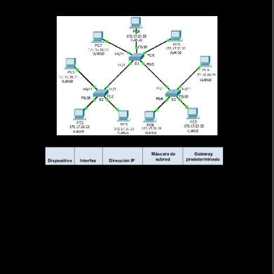
Ennio Torres 3.1.2.7 Packet Tracer - Investigating A Vlan Implementation Instructions 3c4h1f
September 2021 0
Specification For External 3lpe 2n6o1m
December 2019 54
Juan Pablo Jaramillo Valencia 10-2. (1) 5on68
July 2021 0
La Filosofia Ellenistica Tra Epicureismo E Stoicismo. 39395f
December 2019 29
Lo Stoicismo In Seneca 1r3d3s
November 2019 39