Revit 2019 Fundamentals For Mep - Part 1.pdf 6p5d61
This document was ed by and they confirmed that they have the permission to share it. If you are author or own the copyright of this book, please report to us by using this report form. Report 2z6p3t
Overview 5o1f4z
& View Revit 2019 Fundamentals For Mep - Part 1.pdf as PDF for free.
More details 6z3438
- Words: 123,868
- Pages: 576
3 3 O O
o □ □ o o □ o □ u n D D 3 O D 3
ASCENT ::i i\m.iuoK n
KXOH'1.1I'H.II.
Autodesk® Revit® 2019 Fundamentals for MEP Part 1 Learning Guide Metric Units - 1st Edition
3 3 3 3
D D ^AUTODESK
D
Authorized Publisher
OOOOOOOOOOOOUOOOUUUUUUUUUUuuuuuuu
D O O D O D D
□
D D O D O 3 D
□ D D O D O
o D D
D D D D D D D D D
ASCENT - Center for Technical Knowledge Autodesk® Revit® 2019 Fundamentals for MEP - Part 1
®
Metric Units - 1sl Edition
Prepared and produced by:
is,
ASCENT Center for Technical Knowledge 630 Peter Jefferson Parkway, Suite 175 Charlottesville, VA 22911
866-527-2368
www.ASCENTed.com Lead Contributor: Martha Hollowell
ASCENT ► 1HK III » >. -
ASCENT - Center for Technical Knowledge is a division of Rand Worldwide, Inc., providing custom developed knowledge products and services for lead ng engineering software applications. ASCENT is focused on specializing in the creation of education programs that incorporate the best of classroom learning and technology-based training offerings. We welcome any comments you may have regarding this guide, or any of our products. To us please email: [email protected]. 6 ASCENT - Center for Technical Knowledge, 2018 All rights reserved. No part of this guide may be reproduced in any form by any photographic, electrons, mechanical' or other means or used in any information storage and retrieval system without the written permission of ASCENT, a division of Rand Worldwide, Inc, The following are ed trademarks or trademarks of Autodesk, Inc., and/or its subsidiaries and/or s in the USA and other countries: 123D. 3ds Max, Alias ATC, AutoCAD LT, AutoCAD, Autodesk, the Autodesk logo, Autodesk 1230 Autodesk Homestyler, Autodesk Inventor, Autodesk MapGuide, Autodesk Streamline, AutoLISP, AutoSketch. AutoSnap, AutoTrack, Backburner, Backdraft. Beast, BIM 360, Burn, 8uzzsaw, Cep, CAiCE, CAMducl. Civil 3D, Combustion, Communication Specification, Configurator 360, Constructware. Content Explorer. Creative Bridge. Dancing Baby (image), DesignCenter, DesignKids. Des:gnStudio Discreet DWF, DWG, DWG (design/logo), DWG Extreme. DWG TrueConvert, DWG TrueView DWGX, DXF, Ecolect, Ember, ESTmep, FABmep, Face Robot, FBX, Fempro. Fire, Flame, Flare. Flint, ForceEffect. Form t 360, Freewheel. Fusion 360, Glue. Green Building Studio, Heidi, Homestyler, HumanIK, i-drop, ImageModeler, Incinerator. inferno, InfraWorks, Instructables, Instructables (stylized robot design/logo). Inventor, Inventor HSM Inventor LT. Lustre, Maya. Maya LT, MIMI, Mockup 360. Moldflow Plastics Advisers, Moldflow Plastics Insight. Moldflow, Moondust, Motion8uikJer, Movimenlo, MPA (design/logo) MPA. MPI (design/logo), MPX (design/logo). MPX. Mud box, Navisworks. ObjectARX. ObjectDBX. Opticore, P9, Pier 9. Pixlr, Pixlr-o-matic. Productstream, Publisher 360, RasterOWG, RealDWG. ReCap. ReCap 360. Remote. Revil LT. Revit, RiverCAD. Robot, Scaleform, Showcase, Showcase 360, SketchBook, Smoke. Soda'cam, Softimage, Spark & Design, Spark Logo, Sparks, SteenngWheels, Stitcher, Stone. SlormNET. TinkerBox, Tinkercad Tinkerplay ToolClip. Topobase, Toxik, TrustedDWG. T-SpSnes. ViewCube Visual L SP. Visual VRED. Wire. Wiretap, WiretapCentral, XSI. NASTRAN is a reg stored trademark of the National Aeronautics Space stration. Allother brand names, product names or trademarks belong to their respective holders. Genera i Discaimer: Notwthstand ng any language to the contrary, nothing contained herein constitutes nor is intended to constitute an offer inducement, promise, or contract of any kind The data contained herein is for informational purposes only and is not represented to be error free. ASCENT, its agents and employees expressly disdaim any ability for any damages, losses or other expenses arising in connection with the use of its materials or n connection with any failure of performance, error, omission even if ASCENT, or its representatives, are advised of the possibility of such damages, losses or other expenses. No consequential damages can be sought against ASCENT or Rand Woridwde, Inc. for the use of these materials by any third parties or for any direct or indirect result of that use. The information contained herein is intended to be of general interest to you and is provided "as is* and it does not address the circumstances of any particular individual or entity. Nothing herein constitutes professional advice, nor does it constitute a comprehensive or complete statement of the issues discussed thereto ASCENT does not warrant that the document or information will be error free or will meet any particular criteria of performance or quality. In particular (but without limitation) information may be rendered inaccurate by changes made to the subject of the materials (i.e. applicable software). Rand Worldwide. Inc. specifically disclaims any warranty, either expressed or implied, including the warranty of fitness for a particular purpose-
AS-RME1901-FND1MT-SG1 II IS-RME1901-FND1MT-SG1
nnnnnnnnnnnnnnnoooaoooooooooooooo
r-'i,
rr
IE
Wm
mUi
r
ij
!=1t
H8L.
««r rfT
r "i.
X'
IA
(ft
<*?
L-J
]Ttfa5w
ontenl
Jr. ?.
5twnfc-»
TP fa
M
n
Preface
r~\
In this Guide
xv
Practice Files
xix
Chapter 1: Introduction to BIM and Autodesk Revit
1-1
r
C-
r_\
xi
1.1 BIM and Autodesk Revit.................................. Workflow and BIM......... .............................. . Revit ...,................................................... Revit and Construction Documents....................
1-2
1.2 Overview of the Interface................................
1-6
1.3 Starting Projects.............................................. Opening Projects....,.................................. ........ Starting New Projects................................. ...... Saving Projects.......................... ......................
1-20 1-21 1-24 1-25
1.4 Viewing Commands......................................... Zooming and Panning........................................ Viewing in 3D...................... .............................. Visual Styles,....................................................
1-28 1-28 1-30 1-34
Practice 1a Open and Review a Project................ .
1-36
Chapter Review Questions..................................... .
1-45
Command Summary................................................
1-47
Chapter 2: Basic Sketching and Modify Tools........... .
2-1
2.1 Using General Sketching Tools...................... Drawing Aids.............................................. . Reference Planes................................ ........
2-2 2-2 2-6
2.2 Inserting Components.................................... Loading Components....... ................................ Purging Unused Components...........................
2-8 2-13 2-14
©2018, ASCENT - Center for Technical Knowledge®
1-3 1-4 1-5
i
Autodesk Revit 2019: Fundamental for MEP
Practice 2a Insert Components.............................
2-15
2.3 Selecting and Editing Elements.................... Selecting Multiple Elements............................. Filtering Selection Sets....................................
2-21 2-24 2-26
Practice 2b Select and Edit Elements...................
2-28
2.4 Working with Basic Modify Tools................. Moving and Copying Elements......................... Rotating Elements........................................... Mirroring Elements........................................... Creating Linear and Radial Arrays...................
2-33 2-33 2-35 2-37 2-38
Practice 2c Work with Basic Modify Tools...........
2-42
2.5
2-48 2-48 2-50 2-50 2-52
Working with Additional Modify Tools......... Aligning Elements............................................. Splitting Linear Elements.................................. Trimming and Extending...................... *........... Offsetting Elements........................... ..............
Practice 2d Work with Additional Modify Tools
2-55
Chapter Review Questions....................................
2-61
Command Summary...............................................
2-64
Chapter 3: Starting Systems Projects.............
ii
3-1
3.1 Linking and Importing CAD Files ...
3-2
3.2
Linking in Revit Models..................... Managing Links.....................................
3-5 3-7
Practice 3a Start a Systems Project..........
3-9
3.3 Setting Up Levels................................ Modifying Levels.....................*............ Creating Plan Views.............................
3-12 3-14
3-17
3.4
3-19
Copying and Monitoring Elements..
o o o O O O O
o o Q
a G G
a G G G
c:
c
C
c: c c
Practice 3b Copy and Monitor Elements
3-21
3.5 Coordinating Linked Models.............
3-26
C
Practice 3c Coordinate Linked Models ...
3-29
C
3.6
Batch Copying Fixtures..................... Batch Copying Fixtures........................
3-33 3-35
Practice 3d Batch Copy Fixtures...............
3-37
Chapter Review Questions........................
3-45
Command Summary...................................
3-47
© 2018, ASCENT - Center for Technical Knowledge®
c C
c c c c c c
o o O
u D
o o
Contents Part 1 Chapter 4: Working with Views...............................................
4-1
4.1 Setting the View Display............................................ Hiding and Overriding Graphics................................... MEP System Filters...................................................... View Properties............................................................ Using View Templates..................................................
4-2 4-2 4-8
4-10 4-16
4.2 Duplicating Views....................................................... Duplication Types.........................................................
4-18
4-18
Practice 4a Duplicate Views and Set the View Display
4-21
4.3 Adding Callout Views................................................ . Modifying Callouts.......................................................
4-26 4-27
Practice 4b Add Callout Views......................................... .
4-30 4-37 4-38
D
4.4 Creating Elevations and Sections............................ Elevations.................................................................... Sections....................................................................... Modifying Elevations and Sections..............................
4-39 4-39
n
Practice 4c Create Elevations and Sections...................
4-44
Chapter Review Questions...............................................
4-52
Command Summary..........................................................
4-55
D D
□
T
D
□
)
D
Chapter 5: Setting Up Spaces...............
5-1
5.1 Preparing a Model for Spaces
5-2
5-6
5.2 Adding Spaces.......................... Naming Spaces.......................... Creating Individual Spaces......... Space Properties........................
5-9 5-10
Practice 5a Add Spaces...................
5-11
5.3 Working with Spaces................ Special Space Situations............
5-17 5-18
5-7
Practice 5b Work with Spaces.........
5-23
Chapter Review Questions..............
5-32
Command Summary.........................
5-34
Chapter 6: Heating and Cooling Loads Analysis
6-1 6-2
6.1 Creating Zones............................................ Using the System Browser with Zones........
6-4
6.2 Applying Color Schemes...........................
6-6
Practice 6a Create Zones................... ................
6-8
© 2018, ASCENT - Center for Technical Knowledge®
iii
6.3 Analyzing the Heating and Cooling Loads..........................
6-14
Practice 6b Heating and Cooling Analysis...............................
6-20
o o o
Chapter Review Questions.........................................................
6-29
O
Command Summary............................ ......................................
6-31
Chapter 7: Basic Systems Tools....................................................
7-1
7.1 Connecting Components.................................................. Testing Connections............................................................
7-2 7-6
Practice 7a Connect Components............................................
7-8
7.2 Creating Systems - Overview............................................ Using the System Browser...................................................
7-16 7-19
Practice 7b View and Create Systems......................................
7-23
Chapter Review Questions........................................................
7-31
Command Summary..................................................................
7-32
Chapter 8: HVAC Networks.............................................................
8-1
8.1 Adding Mechanical Equipment and Air Terminals.......... Mechanical Equipment......................................................... Air Terminals........................................................................
8-2 8-2 8-4
Autodesk Revit 2019: Fundamentals for MEP
Iv
o O O
o O O O G G G G G
Practice 8a Add Mechanical Equipment and Air Terminals
8-11
8.2 Adding Ducts and Pipes.................................................... Mechanical Settings............................................................. Adding Ducts and Pipes....................................................... Creating Parallel Pipes.........................................................
8-18
8-19
C
8-20 8-24
c
Practice 8b Add Ducts and Pipes..............................................
8-27
8.3 Modifying Ducts and Pipes............................................... Adding Fittings & Accessories.............................................. Duct and Pipe Sizing............................ .......*...................... Converting Ducts and Pipes..........................................,..... Adding Insulation and Lining................................................ Modifying the Justification....................................................
8-33 8-34 8-36 8-37
8-39 8-40
C
C
c c
c
Practice 8c Modify Ducts and Pipes.........................................
8-42
c
Chapter Review Questions........................................................
8-51
Command Summary...................................................................
8-54
Chapter 9: Plumbing Networks.......................................................
9-1
9.1 Adding Plumbing Fixtures and Equipment........................ Mechanical Equipment................. ............................... ....... Plumbing Fixtures................................................................
9-2 9-2 9-4
C C C
© 2019, ASCENT - Center for Technical Knowledge®
c C C C C
□ D
o D
□
D D D D D
□
D D D
□ D D
Contents Part 1 Practice 9a Add Plumbing Fixtures and Equipment....
9-7
9.2 Adding Plumbing Pipes............................................ Adding Pipes............................................................... Sloped Piping.............................................................. Creating Parallel Pipes................................................
9-15 9-17
Practice 9b Add Plumbing Pipes......................................
9-24
9.3 Modifying Plumbing Pipes........................................ Pipe Fittings & Accessories......................................... Changing the Slope..................................................... Converting Pipes......................................................... Adding Insulation......................................................... Modifying the Justification...........................................
9-32 9-32 9-35 9-35 9-36 9-37
Practice 9c Modify Plumbing Pipes.................................
9-39
9-20 9-21
9.4 Adding Fire Protection Networks.............................
9-49
Practice 9d Add Fire Protection Networks......................
9-50
Chapter Review Questions...............................................
9-54
Command Summary..........................................................
9-56
Chapter 10: Advanced Systems for HVAC and Plumbing
10-1
10.1 Creating and Modifying Systems............................. Modifying Systems............ ...................... ...................
10-2 10-5
Practice 10a Create and Modify HVAC Systems.............
10-7
Practice 10b Create and Modify Plumbing Systems....
10-11
□
10.2 Creating Automatic Layouts.....................................
10-15
Practice 10c Create Automatic HVAC Layouts...............
10-19
D
Practice 10d Create Automatic Plumbing Layouts.........
10-26
3
10.3 Testing Systems........................................................ Showing Disconnects............................................ . System Inspector............... ........................................ Duct and Pipe Color Fill Legends................................ Analyzing Systems with Schedule......................
10-31 10-32 10-35 10-37 10-39
Practice 10e Test HVAC Systems.............................. ......
10-40
Practice 10f Test Plumbing Systems...............................
10-49
Chapter Review Questions...............................................
10-55
Command Summary..........................................................
10-57
Chapter 11: Electrical Systems.............................................
11-1
11.1 About Electrical Systems..................................... . Electrical Settings..........*.............................................
11-2 11-3
r“*i
D 3
D
J
© 2018, ASCENT - Center for Technical Knowledge®
v
Autodesk Revit 2019: Fundamentals for MEP
11.2 Placing Electrical Components............ Electrical Equipment...... .......................... Electrical Devices........ ............................ Lighting Fixtures.......... ............................
11-5 11-5 11-6 11-6
Practice 11a Place Electrical Components
11-12
11.3 Creating Electrical Circuits................... Editing Circuit Paths................................. Adding Wires............................................
11-16 11-18 11-20
Practice 11b Create Electrical Circuits.........
11-22
11.4 Setting up Schedules.................. Creating Schedules................ . Modifying Schedules......................
11-30 11-31 11-32
Practice 11c Set Up Schedules...........
11-33
11.5 Adding Cable Trays and Conduit.......... Creating Parallel Conduit Runs................ Modifying Cable Tray and Conduit........... Adding Fittings............... .........................
11-36 11-40 11-41 11-44
11.6 Testing Electrical Layouts.....................
11-45
Practice 11d Add Conduit..............................
11-49
Chapter Review Questions............................
11-53
Command Summary.......................................
11-55
o o o o o o o G O O O G
a a a a G G C G C
C G C C
c
vi
© 2018, ASCENT - Center for Technical Knowledge®
c c c c c c c
M\l[
mm
M|
JS
*E
-f
iii .Has 'ti^ifliy ,
w mr-iiM 4
mb biri
-4-
{
'- , M - I
3 3 3
Conte n m 2 Part i
;m ..
M
i
Preface
xi
In this Guide
xv
Practice Files
xix
Chapter 12: Creating Construction Documents...........
12-1
12.1 Setting Up Sheets............................................. Sheet (Title Block) Properties .................... *.... ..
12-2 12-4
12.2 Placing and Modifying Views on Sheets.........
12-5
Practice 12a Create Construction Documents.......
12-12
12.3 Printing Sheets.................................................. Printing Options...................................................
12-18 12-18
Chapter Review Questions.......................................
12-22
Command Summary..................................................
12-24
Chapter 13: Annotating Construction Documents....
13-1
13.1 Working with Dimensions................................ Modifying Dimensions........ ................................ Setting Constraints..............................................
13-2 13-4 13-7
Practice 13a Work with Dimensions........................
13-13
13.2 Working With Text............................................. Editing Text......................................................... Spell Checking.................................................... Creating Text Types..................... .................... .
13-20 13-23 13-27 13-28
13.3 Adding Detail Lines and Symbols................... Using Symbols........................ ...........................
13-29 13-31
Practice 13b Annotate Construction Documents.
13-33
13.4 Creating Legends..............................................
13-41
Practice 13c Create Legends...................................
13-43
k.->
□ 3 3 3 3 3 f -\
n 3
© 2015, ASCENT - Center for Technical Knowledge®
vri
-4
Autodesk Revit 2019; Fundamentals for MEP
vir
Chapter Review Questions......................................
13-51
Command Summary.................................................
13-53
Chapter 14: Adding Tags and Schedules.....................
14-1
14.1 Adding Tags...................................................... Tagging in 3D Views...........................................
14-2 14-7
o o o o o O
o o o
Practice 14a Add Tags - All Disciplines..................
14-8
14.2 Working with Schedules.................................. Modifying Schedules.......................................... Modifying a Schedule on a Sheet.......................
14-14 14-15 14-17
Practice 14b Work with Schedules - Mechanical
14-18
Practice 14c Work with Schedules - Electrical....
14-24
Chapter Review Questions......................................
14-29
Command Summary.................................................
14-30
Chapter 15: Creating Details.........................................
15-1
15.1 Setting Up Detail Views................................... Referencing a Drafting View.............................. Saving Drafting Views.......................................
15-2 15-4
15.2 Adding Detail Components............................. Detail Components............................................. Repeating Details..............................................
15-8
15-8 15-10
15.3 Annotating Details............................................ Creating Filled Regions..................................... Adding Detail Tags............................................
15-12 15-12 15-14
Practice 15a Create a Fire Damper Detail..............
15-16
Practice 15b Create a Meter Pedestal Detail.........
15-23
G G G G
Practice 15c Create a Floor Drain Detail................
15-24
C
Chapter Review Questions.....................................
15-25
Command Summary................................................
15-27
G G
Appendix A: Introduction to Worksets........................
A-1
A.1 Introduction to Worksets.................................. Saving Workset- Related Files.......... ...............
A-2 A-4
Command Summary................................................
A-7
15-5
© 2018, ASCENT - Center for Technical Knowledge®
O O O O O
o a o
c
c
c c c c c c c
D D
Contents Part 2 Appendix B: Additional Tools..................................................
B-1
B.1 Building Type Settings..................................................
B-2
B.2 Defining Color Schemes...............................................
B-4
B.3 Custom Duct and Piping Types.................................. .
B-7 B-9
□
B.4 Work with System Graphics......................................... System Graphic Overrides........................................... Using Graphic Override Filters......................................
B-11
B.5 Pressure Loss Reports.................................................
B-13
D
B.6 Guide Grids and Sheets................................................
B-16
o
B.7 Revision Tracking.........................................................
B-17
B.8 Annotating Dependent Views....................................... Annotating Views...........................................................
B-22 B-23
B.9 Importing and Exporting Schedules............................
B-25
B.10 Creating Building Component Schedules................. Fields Tab............ ........................................................ Filter Tab........... ................. .....................,....... ........... Sorting/ Grouping Tab.................... ..............................
Schedule Properties......................................................
B-27 B-28 B-29 B-30 B-31 B-32 B-33
B.11 Keynoting and Keynote Legends.............................. Keynote Legends.........................*....... .......................
B-34 B-37
o
Command Summary...........................................................
B-39
D D
Appendix C: Autodesk Revit Certified Professional Exam for Mechanical Building Systems Objectives........................
C-1
□
Appendix D: Autodesk Revit Certified Professional Exam for Electrical Building Systems Objectives............................
D-1
□
Index
□ □ o D
o
D
□ o D O O D
o
Formatting Tab.,........ ................................... Appearance Tab........... ,............... .......... .
B-9
Index-1
o
□ D O D O D D
□
S 2018 ASCENT - Center for Technical Knowledge®
ix
o o o o o o o o o
Autodesk Revit 2019: Fundamentals for MEP
G O G G G G
a G G G G C G G G C
x
© 2018, ASCENT - Center for Technical Knowledge®
c c c c c c c c
n
-m
-Baa I V '
If
I
If]
v
4§*r r-ifP
*
Jj.
Pref
m tea
i_-~r <4
r.y'
|l —?
LH- ii-L-UlZI
4
■
■
tilTOilg
To take full advantage of Building Information Modeling, the Autodesk® Revif® 2019: Fundamentals for MEP guide has been designed to teach the concepts and principles of creating 3D parametric models of MEP system from engineering design through construction documentation. The learning guide is intended to introduce students to the software’s interface and the basic HVAC, electrical, and piping/plumbing components that make the Autodesk Revit software a powerful and flexible engineering modeling tool. The learning guide will also familiarize students with the tools required to create, document, and print the parametric model. The examples and practices are designed to take the students through the basics of a full MEP project from linking in an architectural model to construction documents. Topics Covered:
U
D D tj
•
Working with the Autodesk Revit software’s basic viewing, drawing, and editing commands.
•
Inserting and connecting MEP components and using the System Browser.
•
Working with linked Revit files and CAD files.
•
Creating spaces and zones so that you can analyze heating and cooling loads.
•
Creating HVAC networks with air terminals, mechanical equipment, ducts, and pipes.
•
Creating plumbing networks with plumbing fixtures and pipes.
•
Creating electrical circuits with electrical equipment, devices, and lighting fixtures and adding cable trays and conduits.
•
Creating HVAC and plumbing systems with automatic duct and piping layouts.
•
Testing duct, piping and electrical systems.
•
Creating and annotating construction documents.
•
Adding tags and creating schedules.
•
Detailing in the Autodesk Revit software.
© 2018, ASCENT - Center for Technical Knowledge®
xi
Autodesk Revit 2019: Fundamentals for MEP
Prerequisites •
Access to the 2019 version of the software. The practices and files included with this guide might not be compatible with prior versions.
*
This learning guide introduces the fundamental skills in learning the Autodesk Revit MEP software. It is highly recommended that students have experience and knowledge in MEP engineering and its terminology.
Note on Software Setup This guide assumes a standard installation of the software using the default preferences during installation. Lectures and practices use the standard software templates and default options for the Content Libraries. Students and Resources
Educators
can
Access
Free
Autodesk
Software
and
Autodesk challenges you to get started with free educational licenses for professional software and creativity apps used by millions of architects, engineers, designers, and hobbyists today. Bring Autodesk software into your classroom, studio, or workshop to learn, teach, and explore real-world design challenges the way professionals do. Get started today - at the Autodesk Education Community and one of the many Autodesk software applications available. Visit www.autodesk.conVeducation/home/ Note: Free products are subject to the and conditions of the end- license and services agreement that accompanies the software. The software is for personal use for education purposes and is not intended for classroom or lab use.
o o o o o G G C
a a
□
G G G G G G G G G
C V,
G
C C C
xii
© 2018, ASCENT - Center for Technical Knowledge®
c c c c c c c
D D D D D D D O
D D O ^j
D
D
Preface
Lead Contributor: Martha Hollowell Martha incorporates her ion for building design and education into all her projects, including the training guides she creates on Autodesk Revit for Architecture, MEP, Structure, and landscape design. She has worked with Autodesk products since the 1990’s and has focused primarily on Autodesk Revit for the last 18 years. After receiving a B.Sc. in Architecture from the University of Virginia, she worked in architectural offices and consulted with firms setting up and customizing AutoCAD for their companies. Martha has over 20 years' experience as a trainer and instructional designer. She is skilled in leading individuals and small groups to understand and build on their potential. Martha is trained in Instructional Design and has achieved the Autodesk Certified Instructor (ACI) and Autodesk Certified Professional designations for Revit Architecture. Martha Hollowell has been the Lead Contributor for Autodesk Revit Fundamentals for MEP since its initial release in 2011.
D
Z) LJ
D
□ D D
□ D O
D D D D D D D
D
© 2018, ASCENT - Center for Technical Knowledge®
xiii
o o o o o o o o o o o o
Autodesk Revit 2019: Fundamentals for MEP
G G G G G C
C C
c c
c c
c
c
c c c c G
xiv
© 2018, ASCENT - Center for Technical Knowledge©
c C
i u;
i*i
7k
j
m
n;‘."
m
■*
n this Gui
im
jfrj j|jjrefeHt
mar !W2 B
T
ji^R
&tW-
3
*
ri ti
mu
K»[R7a '
The following images highlight some of the features that can be found in this guide.
D
mm. - Fne» w T nr rtj
9
vm
i
r T)P* '>*1 VNO-n (Mr* r"*» t* — »c+r m »*—■ • r~ «»-»rg w MOf"T «•■<*
Practice Files r—N
m
© rrtHMO.Wrt
The Practice Files page tells you how to and install the practice files that are provided with this guide.
I «•
« UVX«M
l^i/ICCM
’•« «v3 W.*. l«r<»uiin«a r>wi«
r>»
*4
Link to the practice files
ntn nMri uWM
IrttpJ^wwwASCEMW conV9«tlit«7M'»»bii.<
—•-XX* •*«
wr*v i
i im w
iti
rChapter
Chapters
Getting Started PniiTue**
*o*
b
uHiu pont^OMa MvMrcnr*Aja:AP^im
J
'
W^\
ft
\o*yw*i
Each chapter begins with a brief introduction and a list of the chapter's Learning Objectives.
Learning Objectives for the chapter
\
- •** W *o c
J ■*»
<£2018, ASCENT - Center for Technical Knowledge®
)
WH-KII-i
xv
-H ■
gr
Autodesk Revit 2019; Fundamentals for MEP
1.3 Wording with Commands Sorting Command*
issL
> r»
Instructional Content
Cow-afl
h"*
r
r< -u-« rl a
—1 mn/i *■« I* ef-S • i ♦ «**»•
'-’i *
IB s S/de nofes
V'4' •«*” ve:«trw
T«
»
I)
W•(
w**1
U
'»«*-n
Side notes are hints or additional information for the current topic.
■’ST"
Each chapter is split into a series of sections of instructional content on specific topics. These lectures include the descriptions, step-by-step procedures, figures, hints, and information you need to achieve the chapter's Learning Objectives.
r-;;^ :u^~— ‘^*1 M
WW^rX-TV
M»|W"
Practice 1c Saving a Drawing File
Practice Objectives ;
Practices I *
'
I* ft! KXK* 19*
*
WW t 1-41
Practices enable you to use the software to perform a hands-on review of a topic,
»m**a*a
:,g v*kry
o^n
m
<*-« ra» r*#
omi
*•*
Some practices require you to use prepared practice files, which can be ed from the link found on the Practice Files page.
wru Tw*«r caoiOcOvt; m**
»
1 I**C*
►«»
avoOI
0p«« Wft
I
Chapter Review Questions
’ ,zzr‘
* *•«•»>»>• ' t
Chapter Review Questions
c iNn *rh O **■»»••Cc*«>*r' r*-i »ou c*>W •
;
cm
p Fl>U-fM>
.i. (O'.i-w mww'
^ PlMi'fK-
•
t. h.li •* /. Nil -frM*
Chapter review questions, located at the end of each chapter, enable you to review the key concepts and learning objectives of the chapter
J itwCm»C*W> »"dll*ldWrw»«
5 iwni^n
xvi
O
o a o G G G G G G C
c
c c
c c c
W*«. MI
» m *•
o o o o o o o
© 2018, ASCENT - Center for Technical Knowledge®
c c c c c C C C
c
D
in this Guide
D
D
Command Summary
D D
TV
• » ka> iN :o'w*«->d 4^4 *><•«■■ > *M&- ■»**-» a W
Command Summary Q
The Command Summary is located at the end of each chapter. It contains a list of the software commands that are used throughout the chapter, and provides information on where the command is found in the software.
ri •t,
D
□ D
=» itz
D
Q *■
si is.
D
•••-
□
22.
D D
D D D
D
*1 T
M'
Appendix
It
V
Certification Exam Objectives t* ♦>•
lx-
X'
r
**><■■> 1 N >43n *> ►•'p ^ mi • e K *a£AD rp H fVotMM'af ifVo I (IM tw warn
»H*l,
D
i
Autodesk Certification Exam Appendix This appendix includes a list of the topics and objectives for the Autodesk Certification exams, and the chapter and section in which the relevant content can be found.
“is—. ;*7.—
cj
D D
D D D D D D
□ D
D D D D
© 20 f 8, ASCENT - Center for Technical Knowledge®
xvii
o o o o o o o
Autodesk Revit 2019: Fundamentals for MEP
G
c
c
G
C G C C G G C C
C C
C C C C C
xviH
£> 2018, ASCENT - Center for Technical Knowledge®
c c c c c c C
n mi
Ml
r~
.4
wuHi
V
r-V r~
.jp?j ApI4
v
:.*r
j^,
actice Fil
H
'H»*ilfe' -w
m
i“
■1*
Wt~
-i -
dC3 mmm pH r “••Hi
‘V
To the practice files for this guide, use the following steps:
V-J
1. Type the URL shown below into the address bar of your Internet browser. The URL must be typed exactly as shown. If you are using an ASCENT ebook, you can click on the link to the file. Address bar A- https://www.ASCENTed.com/getfile?id=suillus
P-
File Edrt View Favorites Tools Help
2. Press <Enter> to the .ZIP file that contains the Practice Files. 3. Once the is complete, unzip the file to a local folder. The unzipped file contains an .EXE file.
r
4. Double-click on the .EXE file and follow the instructions to automatically install the Practice Files on the C:\ drive of your computer. K -
r*.
)
Do not change the location in which the Practice Files folder is installed. Doing so can cause errors when completing the practices.
https://www.ASCENTed.com/getfile7idssuillus
D Stay Informed!
BME
Interested in receiving information about promotional offers, educational events, invitations to complimentary webcasts, and discounts? If so, please visit: www.ASCENTed.com/updates/ r Help us improve our product by completing the following survey: r'-—i
www ASCENTed.com/ You can also us at: [email protected]
<&2018, ASCENT - Center for Technical Knowledge®
m 1
xix
o o o o o o o o
Autodesk Revit 2019: Fundamentals for MEP
G O O
o G O G G G C
c
c c
G
C C
C C
c
c G
xx
® 2018, ASCENT - Center for Technical Knowledge®
c c c C
□ □
alt
l1
!r
III
Chapti
xH
gr-jr*rT
x&- WM*
*c L> ■f H ,j
gwr^ n • ) t1*1
D D D
L
fif
lLG
i Introduction to BIM and Autodesk Revit
Building Information Modeling (BIM) and the Autodesk'* Revit® software work hand in hand to help you create smart, 3D models that are useful at all stages in the building process. Understanding the software interface and terminology enhances your ability to create powerful models and move around in the various views of the model. Learning Objectives in this Chapter
0 r
D
• Describe the concept and workflow of Building Information Modeling in relation to the Autodesk Revit software. • Navigate the graphic interface, including the ribbon (where most of the tools are found), the Properties palette (where you make modifications to element information), and the Project Browser (where you can open various views of the model). • Open existing projects and start new projects using templates. • Use viewing commands to move around the model in 2D and 3D views.
CJ D
O
□ ® 2018, ASCENT - Center for Technical Knowledge®
0
n
1-1
i
Autodesk Revit 2019: Fundamentals for MEP
1.1 BIM and Autodesk Revit Building Information Modeling (BIM) is an approach to the entire building life cycle, including design, construction, and facilities management. The BIM process s the ability to coordinate, update, and share design data with team across disciplines. The Autodesk Revit software is a true BIM product. It enables you to create complete 3D building models (as shown on the left in Figure 1-1) that provide considerable information reported through construction documents, and enables you to share these models with other programs for more extensive analysis.
TiG7
The Autodesk® Revit® software includes tools for architectural, mechanical, electrical, plumbing, and structural design.
*
■-rJL.
m
) ffJT^rj 1,
*?
_ _ — —_ ----- ~
S’
CE3
mr [>•*
Figure 1-1 The Autodesk Revit software is considered a Parametric Building Modeler: •
1-2
Parametric: A relationship is established between building elements: when one element changes, other related elements change as well. For example, if you add an element in a plan view, it also displays in all of the other views.
•
Building: The software is designed for working with buildings and the surrounding landscape, as opposed to gears or highways.
•
Modeler: A project is built In a single file based on the 3D building model, as shown on the left in Figure 1-1. All views, such as plans (as shown on the right in Figure 1-1), elevations, sections, details, construction documents, and reports are generated based on the model.
•
It is important that everyone who is collaborating on a project works in the same version and build of the software.
© 2018, ASCENT - Center for Technical Knowledge®
o o o o o o o o G O O
o Q G G G G
c G
C C
c c c c
c c c c c c c C
3 3 3 3 3 3 D D D O D D D D D 3
Introduction to BIM and Autodesk Revit
Workflow and BIM
In the traditional design process, construction documents are created independently, typically including plans, sections, elevations, details, and notes. Sometimes, a separate 3D model is created in addition to these documents. Changes made in one document, such as the addition of a light fixture in a plan, have to be coordinated with the rest of the documents and schedules in the set, as shown in Figure 1-2.
rnetiODCL
o o O
o o o D n
s>ccnoN2>
/K cuv/rioN2
7 CD2
rn Figure 1-2
o 3 D D 3 3 D 3 O
BIM has changed the process of how a building is planned, budgeted, designed, constructed, and (in some cases) operated and maintained.
In BIM, the design process revolves around the model, as shown in Figure 1-3. Plans, elevations, and sections are simply 2D versions of the 3D model, while and schedules are a report of the information stored in the model. Changes made in one view automatically update in all views and related schedules. Even Construction Documents update automatically with callout tags in sync with the sheet numbers. This is called bidirectional associativity. By creating complete models and associated views of those models, the Autodesk Revit software takes much of the tediousness out of producing a building design.
ruws>
Tttcnooa,
xtiaxtu:#
cuv/moNZ
coz>
< >j
"l
l
<:
A V XCriON2> Figure 1-3
© 2018, ASCENT - Center for Technical Knowledge®
1-3
o
Autodesk Revit 2019: Fundamentals for MEP
Revit
When working in the Autodesk Revit software, it is important to know the typical used to describe items. Views and reports display information about the elements that form a project. There are three types of elements: Model, Datum, and View-specific, as shown in Figure 1-4 and described below: -V Elevation
0.) T 1 ■T £] 0 €3 0 E3
View-specific Element-------
View-specific Element
a
I
Datum Element
i
00
L-?vel
0 ''I
G G
Model Element: Host Model Element: Hosted
o
Figure 1-4
1-4
o o o o o o a
.evel 2 3910
Model Element: Stand-alone—
O O
Views
Enable you to display and manipulate the model. For example, you can view and work in floor plans, ceiling plans, elevations, sections, schedules, and 3D views. You can change a design from any view. All views are stored in the project
Reports
Reports, including schedules, gather information from the building model element that can be presented in the construction documents or used for analysis.
Model Elements
Include all parts of a building such as walls, floors, roofs, ceilings, doors, windows, p umbing fixtures, lighting fixtures, mechanical equipment, columns, beams, furniture, plants and many more. • Host elements other categories of elements. • Hosted elements must be attached to a host element. • Standalone elements do not require hosts.
Datum Elements
Define the project context such as the levels for the floors and other vertical distances, column grids, and reference planes.
View-specific Elements
Only display in the view in which they are placed. The view scale controls their size. These include annotation elements such as dimensions, text, tags, and symbols as well as detail elements such as detail lines, filled regions, and 2D detail components.
©2018, ASCENT - Center for Technical Knowledge®
G G G G G G G C
c
G G C C
c c
c
c c c c
□
Introduction to BIM and Autodesk Revit
D
□ D D D D
o o
• Autodesk Revit elements are “smart”: the software recognizes them as walls, columns, plants, ducts, or lighting fixtures. This means that the information stored in their properties automatically updates in schedules, which ensures that views and reports are coordinated across an entire project, and are generated from a single model.
Revit and Construction Documents
D O
In the traditional workflow, the most time-consuming part of the project is the construction documents. With BIM, the base views of those documents (i.e., plans, elevations, sections, and schedules) are produced automatically and update as the model is updated, saving hours of work. The views are then placed on sheets that form the construction document set. For example, a floor plan is duplicated. Then, in the new view, all but the required categories of elements are hidden or set to halftone and annotations are added. The plan is then placed on a sheet, as shown in Figure 1-5.
o D
□ D
Aukxfcnk AnX
w J
r
D D
•a*
ror
o D D O D D O
f
0 —1----------- t
PMltcl Rani
UnNra wan Oiqtaattt.
0 GDI
o
□
Figure 1-5
o
• Work can continue on a view and is automatically updated on the sheet.
o
• Annotating views in the preliminary design phase is often not required. You might be able to wait until you are further along in the project.
□
D O
n
&>2018, ASCENT - Center for Technical Knowledge®
1-5
o
Autodesk Revit 2019; Fundamentals for MEP
O
1.2 Overview of the Interface
o o
The Autodesk Revit interface is designed for intuitive and efficient access to commands and views. It indudes the ribbon, Quick Access Toolbar, Navigation Bar, and Status Bar, which are common to most of the Autodesk® software. It also includes tools that are specific to the Autodesk Revit software, including the Properties Palette, Project Browser, and View Control Bar. The interface is shown in Figure 1-6. Mxnc
> Klw ■ o>c« ■
B
MfdlJ
Wk-t
•V• Cwy«l
i1
Co**oo**» vw*-
laa-tr*
; b&uiaw:"j ;z ;5 *°<3o ^** a x X (5 m
o o
S? © • -OX CD-
1 r-*<»
53 0 ^ tM
View McAjic
».VxJ^
* C3 l F*»
6 1.
• Roo» PWr 1 • Mk* « |/,;y o r-^-;orrrr
Annyi*
AonrtW*
o o o G
1*9 **
G
Mo*
Curt*
-
il_How-De:
_
c
flew MKnefwall * a
ConftrMit
iii.
(kv ft ion IkvOK* lowh
'w\-
1
F»«i
8
©
5
11284
P»ciVJi«On^
0«F*
Mow
mu*
Cv.lf't' L •>• *
© 7
G
* 3 $*
fcgatfl he a foyKT B-oww- M«tr< S*wpU r.1
3
C
9
a c c
Otnamom
MwK«nKai
,o;
X
c
L' L-i'-l'vj fkxxPt«->
1 . l^-wvj 2• H
Pl*o» \
c c c c
CcAt^CVk
2 • CMrq tlcc OOwM •lOC* fV» I - Pc-ft
i PffMT K>V««4 3D Ik*
10
2
t^9bo^v(6c*5^g OrvUM t*ti *■« - £W
i*» s c? r« a •** *■ Chkon Waf tepbcefrnUncr
•) - ^ ra «
.»
•
S'# 11
(T £3 ft (S \ t> S?
Figure 1-6
1-6
c
G
HPT
1. Quick Access Toolbar
6. Properties Palette
2. Status Bar
7. Project Browser
3. File tab
8. View Tabs
4. Ribbon
9. Navigation Bar
5. Options Bar
10. View Control Bar
© 2018, ASCENT - Center for Technical Knowledge®
c
c C C
c
C C C C
3 D D D
Introduction to BIM and Autodesk Revit
1. Quick Access Toolbar The Quick Access Toolbar (shown in Figure 1-7) includes commonly used commands, such as Open, Save, Undo, Redo, and Print. It also includes frequently used annotation tools, including Measuring tools, Aligned Dimension, Tag by Category, and Text. Viewing tools, including several different 3D Views and Sections, are also easily accessed here.
□ D D
n D
R S’
- ffO - a s • / i® A ©-0(1 Figure 1-7
o D D D
□ D 3 D
□ D r\ L D D
o O D O
Hint: Customizing the Quick Access Toolbar Right-click on the Quick Access Toolbar to change the docked location of the toolbar to be above or below the ribbon, or to add, relocate, or remove tools on the toolbar. You can also right-click on a tool in the ribbon and select Add to Quick Access Toolbar, as shown in Figure 1-8. hotate Ana r Massi«g&Site Collaborate View Manage * Modify
>5
ll'l hi,'] 0:3 0:0
......
Add to Quick Access Toolbar
■HM
“v-s
V ~oj u 1,1 -4 Si X Modify
View Measure
Create
Figure 1-8 The top toolbar also hosts the InfoCenter (as shown in Figure 1-9) which includes a search field to find help on the web as well as access to the Communication Center, Autodesk A360 , the Autodesk App Store, and other help options. Type a keyword of phraie
£ & il Sign In - y (?) ’
Click here to collapse the search field to save screen space.
Figure 1-9
o D O
□ o D
n
© 2018, ASCENT - Center for Technical Knowledge®
1-7
o
Autodesk Revit 2019: Fundamentals for MEP
V
2. Status Bar
O
The Status Bar provides information about the current process, such as the next step for a command, as shown in Figure 1-10.
V J
Click to enter waB start point.
Enter wall end point. (5Z) to close loop. Space flips orientation.
Figure 1-10 • Other options in the Status Bar are related to Worksets and Design Options (advanced tools) as well as selection methods and filters. Hint: Shortcut Menus Shortcut menus help you to work smoothly and efficiently by enabling you to quickly access required commands. These menus provide access to basic viewing commands, recently used commands, and the available Browsers, as shown in Figure 1-11. Additional options vary depending on the element or command that you are using.
c
Cancel Repeat [Thin Lines] Recent Commands
>
Thin Lines (TL) Split Element (SL)
Select Previous
Railing:Sketch Path Find Referring Views
3D View:Camera
Zoom In Region
Delete (DE)
Zoom Out [2x) Zoom To Fit Previous Pan/Zoom Next Pan/Zoom Browsers
>
V Properties
C
Figure 1-11 (
1-8
© 2018, ASCENT - Center for Technical Knowledge®
(
c
3 D
Introduction to BIM and Autodesk Revit
□
3. File Tab
D D 3 D D D
The File tab of the ribbon provides access to file commands, settings, and documents, as shown in Figure 1-12. Hover the cursor over a command to display a list of additional tools. If you click the primary icon, rather than the arrow, it starts the default command.
I
□
Structure Steel Systems Insert Annotate
j • • Si Architecture
'ob B
□
D D
New
►
E 0
Open
□
y
D D
Save
Ef
D D D D D
Save As
►
Export
►
©
Print
►
Lq
Close
O O
Library Saves a copy of all loaded families, ^ the selected fanvly, group, or view to your library.
i®:
(Recent Documents). The documents can be reordered as shown in Figure 1-13. Click (Pin) next to a document name to keep it available.
EH a
Recent Documents
By Ordered List vj | V By Ordered List] •lOJVt By Access Date1*® Ijxojectivt By Size hip'ejxojectiYt By Type
in
Figure 1-13
O
n
Template Saves the current Revit project file as a template.
♦ To display a list of recently used documents, click
□ o
Family Saver the current fani-y
Figure 1-12
D O
□
2l
Project Saves the current Revit project file.
| Options Exit Revit
o o o
Saves current project or family. Saves current project as a template. Save any family, group or view to your library.
© 2018, ASCENT - Center for Technical Knowledge®
1-9
o
Autodesk Revit 2019: Fundamentals for MEP
« To display a list of open documents and views, click iM (Open Documents). The list displays the documents and views that are open, as shown in Figure 1-14. You can use the Open Documents list to change between views.
letel © Open Documents Project! - Elevation: East Project! - Boor Plan: Level 1 BHM-Office-Grids-10 - Reflected Ceiling Plan: First Boor
►
BHM-Off;ce-Grids-10 • Boor Plan: Brst Floor BHM-Office-Grids-lO - Elevation: North
•
Click ^ (Close) to close the current project.
*
At the bottom of the menu, click Options to open the Options dialog box or click Exit Revit to exit the software.
The ribbon contains tools in a series of tabs and s as shown in Figure 1 -15. Selecting a tab displays a group of related s. The s contain a variety of tools, grouped by task. | Architecture Structure Steel Systems Insert Annotate Analyte Massing & Site Collaborate View Manage Add-Ins Modify
m
C> ojo -CJ
K C« '
*!♦ °<3 O ^
V £3io,n - A. Geometry
Select ' Properties Clipboard
Modify
DD □ □ 5]
m -■J & x
^ '’ -♦= ^ = ’ [Sd] pdi 0 -0 View Measure
Create
Figure 1-15 When you start a command that creates new elements or you select an element, the ribbon displays the Modify \ contextual tab. This contains general editing commands and command specific tools, as shown in Figure 1-16. Add-Ins Modify | Place Dimensions
Analyze Massing & Site Collaborate View Manage
DU ED t- V * ~ t oTo
^ dd
1
J "T --4 3 X *ir Modify
1
- ^
: =■ mi
03^, t
View Measure
/C 0 tf8 *
Linear Angular Radial Owmeter Arc Spot Spot Spot Length Elevation Coordinate Slope Dimension
Create
Contextual tab Figure 1-16
1-10
O G O O O O G G G
o
4. Ribbon
& Cut •
o o o
o
Figure 1-14
*1 Si
O
© 2018, ASCENT - Center for Technical Knowledge®
G
c c G
c G G G C G
c c
c c c c c
D D D D O O D
Introduction to BIM and Autodesk Revit
• When you hover over a tool on the ribbon, tooltips display the tool's name and a short description. If you continue hovering over the tool, a graphic displays (and sometimes a video), as shown in Figure 1-17. Align (AL) Aligns one or more elements with a selected element. You can lock the alignment to make sure that other model changes do not affect it.
□ O D
o
A
O D O D
o o G O D O O
o o o O
o O O
o o n
Proa FI for more help
Figure 1-17 •
Many commands have shortcut keys. For example, type AL for Align or MV for Move. They are listed next to the name of the command in the tooltips. Do not press <Enter> when typing shortcuts.
•
To arrange the order in which the ribbon tabs are displayed, select the tab, hold
, and drag it to a new location. The location is ed when you restart the software.
•
Any can be dragged by its title into the view window to become a floating . Click the Return s to Ribbon button (as shown in Figure 1-18} to reposition the in the ribbon.
I
b&mm v o HI*
© 2018, ASCENT - Center for Technical Knowledge®
ciiD o;io TJ
□□ ED 3I X
Return s to Ribbon
Modify
Figure 1-18
1-11
o
Autodesk Revit 2019: Fundamentals for MEP
O Hint: You are always in a command when using the Autodesk Revit software. When you are finished working with a tool, you typically default back to the Modify command. To end a command, use one of the following methods: • • • •
(Modify). in any tab on the ribbon, click Press <Esc> once or twice to revert to Modify. Right-click and select Cancel... once or twice. Start another command.
o G
o o o o o
CD
5. Options Bar The Options Bar displays options that are related to the selected command or element. For example, when the Rotate command is active it displays options for rotating the selected elements, as shown at the top in Figure 1-19. When the Place Dimensions command is active it displays dimension related options, as shown at the bottom in Figure 1-19. Center of rotation: [place] Default
Modify | Multi-Select j O Dis OCopy Angle: 45| Options Bar for Rotate Command
O
o 3
CD O O LJ
Modify | Place Dimensions
Wall centerline ▼ Pick: Individual Reference * Options
Options Bar for Dimension Command Figure 1-19
6. Properties Palette The Properties palette contains several parts, as shown in Figure 1-20. The Type Selector can be found at the top, which enables you to choose the size or style of the element you are adding or modifying. The options available on the palette enable you to make changes to information (parameters). There are two types of properties:
1-12
•
Instance Properties are set for the individual element(s) you are creating or modifying.
•
Type Properties control options for all elements of the same type. If you modify these parameter values, all elements of the selected type change.
© 2018, ASCENT - Center for Technical Knowledge®
c c G G G
a a c a
c
c: c c c: c C
n
□ □ □ □ n D D D
Introduction to BIM and Autodesk Revit
The Properties palette is usually kept open while working on a project to easily permit changes at any time. If it does not display, in the Modify tab>Properties ,
Filter drop-down.
click H (Properties) or type PP.
Instance Properties-
Properties
x
Type Selector M^Ti^bting and Appliance board 480V MCB - Surface 400 A
Basic Wi I
Host
D G D
Sc h edule^potefl lotes 22850X50 VA
Total Demand Factor 74,6171% Total Connected Current 27.43 A Total Estimated Deman. 20.51 A Apparent load Phase A 59% fi? VA Aooarent Load Phase B 90% 67 VA Properties help
|__Appy
Figure 1-20 Options for the current view display if the Modify command is active, but you have not selected an element. If a command or element is selected, the options for the associated element display. You can save the changes by either moving the cursor off of the palette, or by pressing <Enter>, or by clicking Apply. When you start a command or select an element, you can set the element type in the Type Selector, as shown in Figure 1-21. X
You can limit what shows in the drop-down list by typing in the search box.
M_Water Healer - Tankless 2-3 L
Search Box ;vs
M.WSHP • Horizontal ■ High Efficiency - 7-18 VN ■
D
n
ft
ETecfrical - Loads Total Estimated Demand 17050.00 VA
Some parameters are only available when you are editing an element. They are grayed out when unavailable.
o
o o o o o
■*
a
Schedule Header Nol
Access to Type Properties------
□
o o o
Is
0.0 Electrical Eru^keering
n D D O O O
f**
: AjW 11.5
|2200.0
Elevation
Total Connected
U
-1 8j Edit Type
Electrical ^uipment (1) Constraints
7 kW 11 kW 14 kW M_WSHP - Horizontal - High Efficiency - 7-18 kW • 7 kW
Figure 1-21
©2018, ASCENT - Center for Technical Knowledge©
1-13
I
Autodesk Revit 2019: Fundamentals for MEP
•
When multiple elements are selected, you can filter the type of elements that display using the drop-down list, as shown in Figure 1-22.
*
The Properties palette can be placed on a second monitor, or floated, resized, and docked on top of the Project Browser or other dockable palettes, as shown in Figure 1-23. Click the tab to display its associated . 88 Ea t r>‘p*
(common (16) rVlrtion(l! Air Terminal Tags (1) Air Terminals (2) Duct Fittings (4) Duct Tags (1) Ducts (4) Grids (2)
View Template
)
Floor 1
View Name Dependency
; Independent
Properties help
Apply
Properties Project Browser - Modern-Hotel-Final.rvt
c (
C
c G
7. Project Browser The Project Browser lists all views of the model in which you can work (as shown in Figure 1-24) and any additional views that you create, such as floor plans, ceiling plans, 3D views, elevations, sections, etc. It also includes schedules, legends, sheets (for plotting), lists of families by category, groups, and Autodesk Revit Links. The Project Browser displays the name of the active project.
G
C
Figure 1-23
Figure 1-22
o n o o o
X
Project Browser - Projectl Views (Discipline)
A
ji) Electrical f=) Lighting 3 Floor Plans T Lighting
MEP projects are subdivided by discipline.
2 - Lighting 0- Ceiling Plans 1 - Ceiling Elec 2 - Ceiling Elec i£. Power £j Mechanical B HVAC 0 Floor Plans 1 -Mech
Figure 1-24
C
c a c ci c c v4
C G G C G C G G
c c 1-14
©2018, ASCENT - Center for Technical Knowledge®
L.
D D D
Introduction to BIM and Autodesk Revit
D
□ □ □
•
To open a view, double-click on the view name or right-click and select Open.
*
If you no longer require a view, you can remove it. Right-click on its name in the Project Browser and select Delete.
* To rename a view, slowly double-click on the view name and the text highlights as shown in Figure 1-25. You can also right-click on a view name and select Rename... or press
.
D D D
* To display the views associated with a view type, click ® (Expand) next to the section name. To hide the views in
o
the section, click 0 (Collapse). You can also expand and collapse sets using the shortcut menu, as shown in Figure 1-26.
D r\
O
□ O D O D
□ D
Project Browser - Projectl
X
Project Browser - Projectl
X
0 [o] Views (Discipline) 0 Electrical
A
0 [o] Views (Discipline)
A
0 Lighting 0 FloorPlans
| WffliHBBj' 2 - Lighting 0 Ceiling Plans
Figure 1-25
& MIS e
Search... Expand All Collapse Selected Collapse All
Figure 1-26
• The Project Browser can be floated, resized, docked on top of the Properties palette, and customized. If the Properties palette and the Project Browser are docked on top of each other, use the appropriate tab to display the required .
□ O O
o o O
o o
□ o o n
© 2018, ASCENT - Center for Technical Knowledge®
1-15
Autodesk Revit 2019: Fundamentals for MEP
How To: Search the Project Browser 1. In the Project Browser, right-click on a view type (not a view name) and select Search..., 2. In the Search in Project Browser dialog box, type the words that you want to find (as shown in Figure 1-27), and click Next. 3. In the Project Browser, the first instance of that search displays as shown in Figure 1-28,
x
Search in Project Browser
Project Browser - Projectt £ [□] Views (Discipline)
I HVAC[ Next
A
(jj Electrical Previous
l
f=j Mechanical
dose
B HVAC
□ Match case
Figure 1-28
4. Continue using Next and Previous to move through the list. 5. Click Close when you are done. Hint: Setting the Discipline of a View In the default MEP templates, the Project Browser is set to display views sorted by discipline (preset) and sub-discipline (customizable). These are specified in the Properties of the view, as shown in Figure 1-29. X
Properties
©
c
G G G C
c G
c Floor Plan
b§ Edit Type
Floor Plan: 1 - Power Wal Display
Clean alt wall s
Discipline
Electrical
Show Hidden Lines
Architectural Structural Color Scheme Location Mechanical Color Scheme Electrical System Color Schemes Plumbing Default Analysis Display...Coordination Sub-Discipline ; power
G G G
c
*
i=—
--
Figure 1-29
1 16
G O G O G
c c
El Floor Plans 1 - Mech
Figure 1-27
o o o o o o
© 2018, ASCENT - Center for Technical Knowledge®
G C
C
c c c c G
o
Introduction to BIM and Autodesk Revit
D D O D D
8. View Tabs Each view of a project opens in its own tab. Each view displays a Navigation Bar (for quick access to viewing tools) and the View Control Bar, as shown in Figure 1-30. You can drag tabs to other monitors.
□ D
o
Sg-:' 3D Plumbing
4
In 3D views you can also use the ViewCube to rotate the view.
j
D D G
o o
*
□ -E-
1
:
100
t3
9Cx
o
3
9
3s, SHIR unset ft ts J^|,
■________ > ■!• i?J:0
3 UainModd
Figure 1-30 • Click on the tab to switch between views. You can also: • Press
+
. • Select the view in the Project Browser. ♦ In the Quick Access Toolbar or View tab>Windows
*
expand B (Switch Windows) and select the view from the list. Expand the drop-down list at the far end of the tabs, as shown in Figure 1-31. G.,5 1 - Lighting 03 1 - Mech -V 03 I * Plumbing fli 3D Plumbing & East - Mech [xl
o D D
—ipView Control Bar
□ □
14
t
0
D
© "7
\m,<
□ O
x~ -
© 1 - Meth
Navigation Bar
±34
o o
V
East - Meth
24
-a- -q*
D O
D D G D
1 • lighting
Figure 1-31 * To close a tab, press the X that displays when you hover over the tab or the name in the list, as shown in Figure 1-31.
© 2018, ASCENT - Center for Technical Knowledge®
1-17
Autodesk Revit 2019: Fundamentals for MEP
If you have multiple projects open, one view of each project remains open.
• To close all open views except the current view, In the Quick □ Access Toolbar or View tab>Windows , click (Close Inactive Views).
Drag the edge of tiled views to resize them. The other views resize to match.
• To switch between tabbed and tiled views, in the View tab> Windows , click shown in Figure 1-32.
J M«h
□ (Tab Views) or
B (Tile Views), as
' 0 1 Col^lk, X I—5
T
61
T
-{!>- —GJ-
*4- +■
-4- -4*
-Q- -[!>-
O
o a
C2D
-6-
*4- *4* C3D
i:uo
A
cno
g,***!-^ i Q<*.n <
Ult
1
O
<5 |
O
cn i:»oo Bsc.
G
9 aftri <
o
» G 3D °*urr*>«^9
w I
G
i , f v . Vl
'n ■\s
s
ri-
(fl
‘T i IM 06l<xC4«V' « C!ftri(
o o o o o o o o o
I: ICO E3 £# r, y, ■Q rt «5 ^ » C3 nt. (Jr rs «
Figure 1-32
a G
c G G G
c c
c c c
c 1-18
©2018, ASCENT - Center for Technical Knowledge®
c c c
3 D D 3 3 3
Introduction to BIM and Autodesk Revit
9. Navigation Bar The Navigation Bar enables you to access various viewing commands, as shown in Figure 1-33. Q)
□
3 O D 3 D 3 3 n 3 3 3 D 3 D 3
□
3 D 3 3 3 3 3 3 3 3
'J Zoom in Region Zoom Out(2x) Zoom to Fit Zoom All to Fit Zoom Sheet Size Previous Pan/Zoom Next Pan/Zoom
Figure 1-33
10. View Control Bar The View Control Bar (shown in Figure 1-34), displays at the bottom of each view window. It controls aspects of that view, such as the scale and detail level. It also includes tools that display parts of the view and hide or isolate elements in the view. 1: 100
H Q rel="nofollow">
* The number of options in the View Control Bar change when you are in a 3D view.
© 2018, ASCENT - Center for Technical Knowledge®
1-f9
Autodesk Revit 2019: Fundamentals for MEP
1.3 Starting Projects File operations to open existing files, create new files from a template, and save files in the Autodesk Revit software are found in the File tab, as shown in Figure 1-35. R, 0 i53 *<£>'<*>• © S-/I0 A © - O Architecture Structure Steel Systems Insert Annotate
£)je> Opens a Revit compatible file.
D
New
Open
H
C
a IL
Save As
Project Opens a Revtt project.
Family Opens a Revit family.
Revit file Opens any Revit file type.
a,
Building Component Opens a building component Antnrlpslc Fvrhanne (AD^IO file.
Figure 1-35 There are three main file formats:
o o o o o o o o O O O
a G G G G G v..y
•
•
•
1-20
Project files (.rvt): These are where you do the majority of your work in the building model by adding elements, creating views, annotating views, and setting up printable sheets. They are initially based on template files. Family files (.rfa): These are separate components that can be inserted in a project. They include elements that can stand alone (e.g., a table or piece of mechanical equipment) or are items that are hosted in other elements {e.g., a door in a wall or a lighting fixture in a ceiling). Title block and Annotation Symbol files are special types of family files. Template files (.rte and .rft): These are the base files for any new project or family. Project templates hold standard information and settings for creating new project files. The software includes several templates for various types of projects. You can also create custom templates. Family templates include base information for creating families. Template files are usually saved as a new file.
©2018, ASCENT - Center for Technical Knowledge®
c G C
C G C C C C C
c c c c C
D
Introduction to BIM and Autodesk Revit
:)
3 3 3 3 3 3 D D D
Opening Projects
To open an existing project, in the Quick Access Toolbar or File tab click S’ (Open), or press
+<0> The Open dialog box opens (as shown in Figure 1-36), in which you can navigate to the required folder and select a project file. ?
R Open
Lookn:
- 4- X H s*"* •”
Various BuMngs
■ '
3
Preview
Type
Name
□
X
DWGs
File folder
HMI_Everywh«e_Table_RectanguIar_Post_Leg_30D60W_rfa_3D
File folder
QBHM-Office.rvt
Autodesk
Rev
Q8HM-Office-2016.rvt
Autodesk
Rev
QCondo.rvt
Autodesk
Rev
QMEP-Elementary-School-Architecturalrvt rvt
Autodesk
Rev
QSteel structure 3 story office.rvt
Autodesk
Rev
KtSteel structure 3 story office-2016.rvt
Autodesk
Rev
QSyracuse-Suites multistory strueture.rvt
Autodesk
Rev
Qlownhouse.rvt
Autodesk Rev
i
Revit 2019
u
n M/r-MKork .
o
&
rJ
Fie name: 9fMOffice rvt
Fa-.-antM Fles of type: AJ ed Fles (“jvt, *.rfa, *.adsk, *.rte) Worksharing
Q 3 3 3
Toofc *
□ Audt
Detach from Centre!
Create New Local
‘Open
Cancel
-1,1
Figure 1-36 • When selecting a project, the software release version of that project displays below the preview. This is a reminder not to open a drawing that should remain in an earlier version. You cannot save back to previous versions.
D D D O
o D
□ O D
o
©2018, ASCENT - Center for Technical Knowledge®
1-21
Autodesk Revit 2019: Fundamentals for MEP
• When you first open the Autodesk Revit software, the Startup Screen displays, showing lists of recently used projects and family files as shown in Figure 1-37. This screen also displays if you close all projects. • eO • ©
R&0
- /' 0 A © • O ?
»
Recent Files
► 11 ypt a iiyiw
I Architectuie Structure Steel Systems Insert Annotate Analyte Massing fit Site Collaborate View Manage At
o G
??
o
■1—MW ji
tffirjLso
Hnra ■■ Construction Template * Architectural Template Structural Template Mechanical Template
Families
i Sample Systems Project
^ Open... • New.. *■* New Conceptual Mass...
IK
T
Sample Architecture
Sample Architecture Project
Sample Structure Project
.r-TlN /frly Sample St'ucture
Sample Systems
Figure 1-37 • You can select the picture of a recently opened project or use one of the options on the left to open or start a new project using the default templates.
1-22
o o o o o o
© 2018, ASCENT - Center for Technical Knowledge®
G G G G G G G G C
c G G G G G C G C C C G C C C
I)
introduction to BIM and Autodesk Revit Hint: Opening Workset-Related Files
D
Worksets are used when the project becomes large enough for multiple people to work on it at the same time. At this point, the project manager creates a central file with multiple worksets (such as element interiors, building shell, and site) that are used by the project team .
1
D D
D
When you open a workset related file it creates a new local file on your computer as shown in Figure 1-38. Do not work in the main central file.
O D
Ffcname: Sam(*e Workset Ftesoftype: Ai ed F*es (*.rvt, m.ifo, *.acbk, *jte, *.rfl) Wortahamg Detach from Central Audi V Create New Local
D
□
L~"
■
Figure 1-38
D D D
• For more information about opening and saving workset-related files, see Appendix A. 1 Introduction to Worksets. • For more information on establishing and using Worksets, refer to the Autodesk Revit: Collaboration Tools learning guide.
f~''\
It is very important that everyone working on a project uses the same software release.
• When you open a file created in an earlier version, the Model Upgrade dialog box (shown in Figure 1-39) indicates the release of a file and the release to which it will be upgraded. If required, you can cancel the upgrade before it completes. Model Upgrade Your model is being upgraded
D O O
From:
Autodesk Revit 2015
To:
Autodesk Revit 2019
When the upgrade is complete, save the model to avoid the need to repeat the process
o G
o
What happens when the model is upgraded7
O
Cancel Upgrade
Figure 1-39
o 0
o r~\
© 2018, ASCENT - Center for Technical Knowledge®
1-23
Autodesk Revit 2019: Fundamentals for MEP
Starting New Projects
New projects are based on a template file. The template file includes preset levels, views, and some families, such as waf! styles and text styles. Check with your BIM Manager about which template you need to use for your projects. Your company might have more than one based on the types of building that you are deg.
How To: Start a New Project
□
Creates a Revit file.
New
B? Open
c
E
Project Creates aRevit project file.
a
Family Creates a set of custom components to use in projects.
Figure 1-40 2. In the New Project dialog box (shown in Figure 1-41), select the template that you want to use and click OK. The list of Template files is set in the Options dialog box in the File Locations pane. It might vary depending on the installed product and company standards.
x
New Project Template fie Construction Template
Browse...
V
c
G C
C G
c
c c
G
Construction Template C Architectural Template Structural Template 1 Mechanical Template
c c
L
OK
Cancel
Help
Figure 1-41 • You can select from a list of templates if they have been set up by your BIM Manager.
1-24
G G G G
Structure Steel Systems Insert Annotatt
<E)B
c C
R. £> 0 !$.<*-•© ss - / l® A © - O [M Architecture
O C G G
^ (Project) (as 1. In the File tab, expand G) (New) and click shown in Figure 1-40), or press
+
.
File
c c
© 2018, ASCENT - Center for Technical Knowledge©
c c c G C C C
c:
D 0 D 0
Introduction to BIM and Autodesk Revit • You can add
end of the Quick Access Toolbar, dick B (Customize Quick Access Toolbar) and select New, as shown in Figure 1-42.
0 D 0
SB-E View Customize Quick Access Toolbar ✓ New * v' Open rJ
□
Figure 1-42
n D 0
□ D D D
□ D D 3 D
o o o o o 0
E-fl (New) to the Quick Access Toolbar. At the
Saving Projects
It is important to save your projects frequently. In the Quick (Save), or press
+<S> Access Toolbar or File tab click to save your project. If the project has not yet been saved, the Save As dialog box opens, where you can specify a file location and name. •
To save an existing project with a new name, in the File tab, expand (Save As) and click 0 (Project).
•
If you have not saved in a set amount of time, the software opens the Project Not Saved Recently alert box, as shown in Figure 1-43. Select Save the project. If you want to set reminder intervals or not save at this time, select the other options. Project Not Saved Recently
X
You have not saved your project recently. What do you want to do?
Save the project —> Save the project and set reminder intervals —> Do not save and set reminder intervals
o Cancel
0
o o o n
Figure 1-43
© 2018, ASCENT - Center for Technical Knowledge®
1-25
Autodesk Revit 2019: Fundamentals for MEP
• You can set the Save Reminder interval to 15 or 30 minutes, 1, 2, or 4 hours, or to have No reminders display. In the File tab, click Options to open the Options dialog box. In the left pane, select General and set the interval as shown in Figure 1^44. X
Options
General Interface
Notifications Save reminder interval: 130 minutes
V
15 minutes Graphics Hardware File locations
Synchronize with Central reminder interval: 30 minutes One how Two hours Four hows name No remrtders
Figure 1-44
Saving Backup Copies By default, the software saves a backup copy of a project file when you save the project. Backup copies are numbered incrementally (e g., My Project.0001.rvt, My Project.0002.rvt, etc.) and are saved in the same folder as the original file. In the Save As dialog box, click Options... to control how many backup copies are saved. The default number is three backups. If you exceed this number, the software deletes the oldest backup file.
o o o o o o o O O O O
o G G G G G C C G C G G G
C G G C
1-26
© 2018, ASCENT - Center for Technical Knowledge®
c c c c c
D
Introduction to BIM and Autodesk Revit
o D D D O D
o o D D
Hint: Saving Workset-Related Projects if you use worksets in your project, you need to save the project locally and to the central file. It is recommended to save the local file frequently, just like any other file, and save to the central file every hour or so by synchronizing with the central file. To synchronize your changes with the main file, in the Quick Access Toolbar expand £3 (Synchronize and Modify Settings) and click J (Synchronize Now). After you save to the central file, save the file locally again. At the end of the day, or when you are finished with the current
o
session, in the Quick Access Toolbar, expand El (Synchronize
D D
and Modify Settings) and click ^ (Synchronize and Modify Settings) to relinquish the files you have been working on to the central file.
D
• The maximum number of backups for workset-enabled files is set to 20 by default.
D D D D O O
o D O
o o Q
o o D
o
© 2018, ASCENT - Center for Technical Knowledge®
1-27
Autodesk Revit 2019: Fundamentals for MEP
1.4 Viewing Commands Viewing commands are crucial to working efficiently in most drawing and modeling programs and the Autodesk Revit software is no exception. Once in a view, you can use the Zoom controls to navigate in it. You can zoom in and out and pan in any view. There are also special tools for viewing in 3D.
Zooming and Panning
Using The Mouse to Zoom and Pan Use the mouse wheel (shown in Figure 1-45) as the main method of moving around the models.
o o o o o o o o o o G O G G G G C
Mouse
c
Figure 1-45 • • • •
Scroll the wheel on the mouse up to zoom in and down to zoom out. Hold the wheel and move the mouse to pan. Double-click on the wheel to zoom to the extents of the view. In a 3D view, hold <Shift> and the mouse wheel and move the mouse to rotate around the model.
• When you save a model and exit the software, the pan and zoom location of each view is ed. This is especially important for complex models.
1 28
© 2018, ASCENT - Center for Technical Knowledge®
c c c c
c c
c c c c c c c
D
Introduction to BIM and Autodesk Revit
□ 3 3 3 3 3 D 3 3 D
Zoom Controls A number of additional zoom methods enable you to control the screen display. Zoom and Pan can be performed at any time while using other commands. • You can access the Zoom commands in the Navigation Bar in the upper right corner of the view (as shown in Figure 1-46). You can also access them from most shortcut menus and by typing the shortcut commands.
s
(2D Wheel) provides cursor-specific access to Zoom and Pan.
<§l V Zoom in Region Zoom Out(2x) Zoom to Fit Zoom All to Fit
3 3 3 3 3 D 3 3 3
□ 3 D D D
Zoom Sheet Size Previous Pan/Zoom Next Pan/Zoom Figure 1-46
Zoom Commands
E
Zoom In Region Zooms into a region that you define. Drag the cursor or select two points to define the (ZR) rectangular area you want to zoom into. This is the default command
S 0
Zoom Out(2x) (ZO)
Zooms out to half the current magnification around the center of the elements.
Zoom To Fit (ZF or ZE)
Zooms out so that the entire contents of the project only display on the screen in the current view.
0 IS
Zoom All To Fit Zooms out so that the entire contents of the (ZA) project display on the screen in all open views. Zoom Sheet Size (ZS)
Zooms in or out in relation to the sheet size.
□ D
□ 3
®2018, ASCENT - Center for Technical Knowledge®
1 29
c c
Autodesk Revit 2019: Fundamentals for MEP
Viewing in 3D
N/A
Previous Pan/Zoom (ZP)
Steps back one Zoom command.
N/A
Next Pan/Zoom
Steps forward one Zoom command if you have done a Previous Pan/Zoom.
c
Even if you started a project entirely in plan views, you can quickly create 3D views of the model, as shown in Figure 1-47. There are two types of 3D views: isometric views created by the Default 3D View command and perspective views created by the Camera command.
c c
=©a
Q
c ( lick or Drag
(
c
f-
L-c-'-J
•—I
i*
f
' 1
c c c
c
IT.--
- - »■ ary - L:
c
c
13'
&
c c c
!\_£w
I ...
c c c
j—
Figure 1-47 Working in 3D views helps you visualize the project and position some of the elements correctly. You can create and modify elements in both isometric and perspective 3D views, just as you can in plan views. • Once you have created a 3D view, you can save it and easily return to it.
c c c c c c c; L
c 1-30
© 2018, ASCENT - Center for Technical Knowledge®
c
D D D D D D D 3 3 D
Introduction to BIM and Autodesk Revit
How To: Create and Save a 3D Isometric View 1. In the Quick Access Toolbar or View tab>Create , click 0 (Default 3D View). The default 3D Southeast isometric view opens, as shown in Figure 1^8. You can spin the view to a different angle using the mouse wheel or the middle button of a three-button mouse. Hold <Shift> as you press the wheel or middle button and drag the cursor.
V
’ Ci
< V Si
® ■ss»
-WS§m w-i4r 3Jljf -'st# H *.
r‘T
□ □ 3
o o o o o o o o o O
f,''
in
Figure 1-48
□
□ □
‘V^ &
^
<>^
w
D 3 D D
mfA
2. Modify the view to display the building from other directions. 3. In the Project Browser, double-click slowly or right-click on the {3D} view and select Rename.... 4. The name is placed in a text box with the original name highlighted, as shown in Figure 1-49. Type a new name in the Rename View dialog box, as shown in Figure 1-50. B 3D Views Perspective View 1
I US) I B Elevations (Elevation 1) 0 Sections (Type 1) Figure 1-49 All types of views can be renamed.
B 3D Views Perspective View 1 Interior Perspective 0 Elevations (Elevation 1) (B Sections (Type 1) Figure 1-50
• When changes to the default 3D view are saved and you start another default 3D view, it displays the Southeast isometric view once again. If you modified the default 3D view but did not save it to a new name, the Default 3D View command opens the view in the last orientation you specified.
©2018, ASCENT - Center for Technical Knowledge€>
1-31
Autodesk Revit 2019: Fundamentals for MEP How To: Create a Perspective View 1. Switch to a Floor Plan view. 2. In the Quick Access Toolbar or View tab>Create ,
a
(Camera). expand t9 (Default 3D View) and click 3. Place the camera on the view. 4. Point the camera in the direction in which you want it to shoot by placing the target on the view, as shown in Figure 1-51. The view displays as shown in Figure 1-52.
c c c c O
c G C
c c
Target
if.
c
/?
G
c
:
c
CLASSROOM 2006
c
/
Ut
c
Camera 3“
Figure 1-51
Figure 1-52 • Use the round controls to modify the display size of the view and press <Shift> + the mouse wheel to change the view. 5. In the Properties palette scroll down and adjust the Eye Elevation and Target Elevation as required. * If the view becomes distorted, reset the target so that it is centered in the boundary of the view (called the crop region). In the Modify \ Cameras tab>Camera , click ^ (Reset Target).
c c c
c
G C G C
c
c c
1-32
c c c c © 2018, ASCENT - Center for Technical Knowledge<©c. r
□
Introduction to BIM and Autodesk Revit
o D O D D D O D O
Hint: Using the ViewCube The ViewCube provides visual clues as to where you are in a 3D view. It helps you move around the model with quick access to specific views (such as top, front, and right), as well as corner and directional views, as shown in Figure 1-53. ViewCube
'~T~
o D D D O D D D D CD
o r-\
□ □ D
o o o
Figure 1-53 Move the cursor over any face of the ViewCube to highlight it. Once a face is highlighted, you can select it to reorient the model. You can also click and drag on the ViewCube to rotate the box, which rotates the model. .
(Home) displays when you roll the cursor over the ViewCube. Click it to return to the view defined as Home. To change the Home view, set the view as you want it, right-click on the ViewCube, and select Set Current View as Home,
* The ViewCube is available in isometric and perspective views. • You can switch between Perspective and Isometric mode by right-clicking on the View Cube and selecting Perspective or Orthographic.
□ o
□ □ D
©2018, ASCENT - Center for Technical Knowledge®
1-33
p
Autodesk Revit 2019: Fundamentals for MEP
Visual Styles
Any view can have a visual style applied. The Visual Style options found in the View Control Bar (as shown in Figure 1-54), specify the shading of the building model. These options apply to plan, elevation, section, and 3D views.
c c c
©Wireframe © Hidden line m> Shaded
w
© Realistic
c c
FUl Ray Trace (S3 y< .p- TW 9 GS ti Figure 1-54
•
•
•
© (Wireframe) displays the lines and edges that make up elements, but hides the surfaces. This can be useful when you are dealing with complex intersections. © (Hidden Line) displays the lines, edges, and surfaces of the elements, but it does not display any colors. This is the most common visual style to use while working on a design. * (Shaded) and ® (Consistent Colors) give you a sense of the materials, including transparent glass. An example that uses Consistent Colors is shown in Figure 1-55.
[i
m\
r**-
H
iM
o p P
Graphic Drsplay Options...
© Consistent Colors
P P
c
c
c
c
G C (
c c c c
c
c: c C
Figure 1-55
c C
c 1-34
© 2018, ASCENT - Center for Technical Knowledge®
c
D
□ o o D D D D D D D D D D D D O
Introduction to BIM and Autodesk Revit
& (Realistic) displays what is shown when you render the view, including RPC (Rich Photorealistic Content) components and artificial lights. It takes a lot of computer power to execute this visual style. Therefore, it is better to use the other visual styles most of the time as you are working. &
(Ray Trace) is useful if you have created a 3D view that you want to render. It gradually moves from draft resolution to photorealistic. You can stop the process at any time.
.)
D D D D D D D D D D
□ □ □ ©2018, ASCENT - Center for Technical Knowledge®
3
1-35
o
Autodesk Revit 2019: Fundamentals for MEP
o o o
Open and Review a Project
Practice 1a
Practice Objectives
o o o
• Navigate the graphic interface, • Manipulate 2D and 3D views by zooming and panning, • Create 3D Isometric and Perspective views. • Set the Visual Style of a view.
In this practice, you will open a project file, as shown in Figure 1-56 and display each of the various parts of the Autodesk Revit interface. You will open views through the Project Browser, and switch between different views. You will also select elements and display the information about them in the Properties palette. Finally you will create and save 3D views.
c
> V.
S.
£$
G
*
<-
If'
N
S3
c
k
$
^u,iL
9
X >TS>
•SX--
a
s
ii
■>
It
XC
>•
K, '■ N.
'V
*v
.Cl
•H
yfL Figure 1-56
• This practice is for all disciplines.
1 36
C G G O G G C
© 2019, ASCENT - Center for Technical Knowledge®
C C C
c
c
c c
c c
c
c c c c c c
o o o o
Introduction to B1M and Autodesk Revit
Task 1 - Open an Autodesk Revit MEP project and review it.
1. In the File tab, expand
o
(Open) and click ^
(Project).
D O D
2. In the Open dialog box, navigate to the Introduction practice files folder and select MEP-Elementary-SchoolReview-M.rvt.
o
3. Click Open.The project opens in the 3D Plumbing view, as shown in Figure 1-56 (above).
D D O
□ D D
□ 3 vj
D )
n O D
4. Close any other open projects and views. 5. In the Project Browser, expand Mechanical>HVAC>Floor Plans and select 01 Mechanical Plan, as shown in Figure 1-57. Project Browser - MEP-Eiementary-School-Review.rvt X □ [o] Views (Discipline) Q Coordination (j] Electrical Q Mechanical EJ HVAC El Floor Plans 01 Mechanical Plan 02 Mechanical Plan Q 3DViews 3D HVAC 5] Plumbing H] Legends E) Schedules/Quantities Figure 1-57
□ D O O D D
□ D u D D
© 2018, ASCENT - Center for Technical Knowledge®
1 37
o
Autodesk Revit 2019: Fundamentals for MEP
O
6. Double-click on 01 Mechanical Plan. The applicable view opens as shown in Figure 1-58.
o o o
-TV1
r>
O
rl fv\
1 I
tTt
-r*
rfe V
r>
ii
7
f
J-i-L
t U—*W
I Souk: I
P3
L
Figure 1-58 7. Use the scroll wheel to zoom and pan around the view. 8. Double-click on the scroll wheel or type ZF (Zoom to Fit) to return to the full view. 9. Expand Plumbing>Plumbing>Floor Plans and double-click on the 01 Plumbing Plan view to open it. 10. Expand Coordination>MEP>Floor Plans and double-click on 01 Space Planning to open this view. 11. All of the previous views are still open and can be see in the tabs, as shown in Figure 1-59. © 3D Plumbing If! 01 Mechanical Plan 0 01 Plumbing Plan 0 01 Space Planning X Figure 1-59
1-38
© 2018, ASCENT - Center for Technical Knowledge®
o o o o o G G G G
a C
c c G G C G C C
c f.
c c C C
c C
□ □ D D D D D D D D D D D D D D 3 D
Introduction to BIM and Autodesk Revit □
12. In the View tab>Windows , click D (Ttle Views) or type WT to display all of the open views on the screen at the same time. 13. Type ZA (Zoom All to Fit) to have the model display completely within each view window, as shown in Figure 1-60. 0 Ol S(M
K - I - I i 1 hi
o o o o o o o o o r\
I£
jft-j- i-l - l-jl 0^______
T i
J
i ijai l: 100 SfiK* i^\ 01
9 Q*rs <
l: 100
Plan
m&<* &.**$'* o caiftrs <
G 3D Plurri-rtg
m
■ 1
£ .. 4
□ G
r*
E
o o o
2 01 Mechanic*! Plan
1: 100
so
FT urafkct5 ^*|
i; too :0
f3 9<* G<-C9 «* *4
•. caft tf>rs <
5- 4 .3, C5 X O ^
^ ! 1j ' '1 Hie
Figure 1-60 14. Click in the open 01 Mechanical Plan view to make it active. 15. In the View tab>Windows , click TW.
□
(Tab View) or type
16. In the Quick Access Toolbar, click 4 (Close Inactive Windows). Only the current active view is open.
© 2018, ASCENT - Center for Technical Knowledge®
1-39
Autodesk Revit 2019: Fundamentals for MEP
Task 2 - Display the Element Properties. 1. In the 01 Mechanical Plan view, hover over a duct without selecting it first. The duct highlights and a tooltip displays as shown in Figure 1-61. Information about the element also displays in the Status Bar but not in Properties.
j ts. i yj—j \
A
5 G
i
'l " 1
1
f Ducts: Rectangular Duct; Radius Elbows / Taps
*
1 1m Ri -i'-
f
J
1
l
Figure 1-61 2. Click on the duct to select it. The selection color and tabs on the ribbon at the top of the screen change. Properties now displays information about this piece of ductwork, as shown in Figure 1-62. Properties
X
Rectangular Duct Radius Elbows / Taps
7J gg Edit Type
Ducts (1) Constraints
s*
*3 u
Horizontal Justification [Center Vertical Justification
i
Reference Level
Middle Floor 1
Offset
|3500.0
Start Offset
13500.0
End Offset
3500,0
Slope
0.0000%
Mechanical System Classification
Return Air
System Type
let um Air
System Name
vies han cal Return Ai.
System Abbreviation APP1y
Figure 1-62
1-40
O O G G G
o G
a G C
c G G G G G
c a
Properties help
o o o o o o o o
© 2018, ASCENT - Center for Technical Knowledge®
G
c c G
c c c (
D D
o D D D
Introduction to BIM and Autodesk Revit
3. Hold
and in the view, select another, similar Duct element, as shown in Figure 1-63. Properties now displays that two ducts (Ducts(2)) are selected with the same information. Selected Ducts
□
UJL\ t^t
o D
a E
■
(i
D 3 D 3 D 3 D 3 3 3 3 D 3 D 3 D D D D 3 3 3
k
-A-flWf i
mm«fBrn
“
I
8
m
Figure 1-63 4. Hold
and select an air terminal. Properties now displays Common (3) in the Filter drop-down list, because the three selected elements are not of the same type. Therefore they do not share the same type of properties. 5. In Properties, expand the Filter drop-down list and select Air Terminals, as shown in Figure 1-64. X
Properties
Muli;pV Categoric* Selected
£drt Type
ICornmon-(3) | Common (3)
A*
Ducts (2) Floor Plan: 01 Mechanical Plan
Figure 1-64 6. Only the Air Terminal properties are displayed, but the selection set has not changed. In the view they are all still selected.
© 2018, ASCENT - Center for Technical Knowledge®
1-41
Autodesk Revit 2019: Fundamentals for MEP
7. End the command using one of the following methods: * In Modify \ Multi-Select tab>Select , click • • *
** (Modify). Press <Esc> twice. Click in the view window (without selecting an element). Right-click in the view window and select Cancel.
Task 3 - Create 3D Views.
(Default 3D View).
1. In the Quick Access Toolbar, click
2. A 3D Isometric view displays, as shown in Figure 1-65.
G G
A
C''
is
o o o o o o o o o o o o a a
c
c c Figure 1-65 3. Press and hold <Shift> and press the middle mouse (scroll) button to orbit the view. 4. In the View Control Bar, select several different Visual Styles to see how they impact the view, as shown in Figure 1-66. 9" Graphic Display Options... £§l Wireframe 0 Hidden Line SI Consistent Colors £» Realistic Ray Trace U?
v GJ ft & T5 Figure 1-66
1-42
c G C C
(3?Shaded
HB^.x Uf *9 JR
G G C C C
© 2018, ASCENT - Center for Technical Knowledge®
c c c c C
D 0
D D D O
□ □ D O D 0 D D D D D 0 O
introduction to BIM and Autodesk Revit
5. Select a view and visual style that you like. 6. In the Project Browser, expand Coordination>AII>3D Views, double-click on (3D) and name the view 3D Exterior and click OK. 7. Save the project. Task 4 - Create a camera view. 1. Switch back to the 01 Mechanical Plan view. 2. In the Quick Access Toolbar, expand
©
(Default 3D View)
GS
and click (Camera). 3. Place the camera and select a point for the target similar to that shown in Figure 1-67. Camera _ Target
rvi rvi
> i
T7
i.
w
i"
il vji
o
\ §/
0
0
o o 0
o o o 0 0 0
o o
Figure 1-67 4. The new view displays. Use the controls on the outline of the view to resize the view. 5. Click inside the 3D view and use <Shift>+ mouse wheel to rotate around until you get a good view of the ductwork. 6. Set the Visual Style, as required.
© 2018, ASCENT - Center for Technical Knowledge®
1-43
G G
Autodesk Revit 2019: Fundamentals for MEP
7. In the Project Browser, expand Mechanical>???>3D Views and select the new 3D View 1 as shown in Figure 1-68.
The new view displays in the??? category because it has not been assigned a Sub-Discipline.
Project Browser - MEP-£!ementaiy-School-Review.rvt X
o o
g [□] Views (Discipline)
G
o
0 Coordination ® Electrical
G G G O G
0- Mechanical Q ??? B 3D Views
3D View 1
-
B HVAC B Floor Plans 01 Mechanical Plan
Figure 1-68
o o
8. In Properties, in the Graphics area, expand Sub-Discipline and select HVAC, as shown in Figure 1-69.
G G G G
9. Click Apply. The view moves to the correct sub-discipline group as shown in Figure 1-70. Rename the view as required.
x
Properties t|Vj 30 View
G ~"j Edit Type
30 View. (3D) Graphics Parts Visibility
s-
Show Hidden Lines By Discipline Default Analysis Display... None
Extents Crop View Properties heto
0
Show Original
Visibility/Graphics Overr... [ ‘Edit... Graphic Display Options [_______ Edit... Mechanical Discipline
Sub-Discipline Sun Path
Project Browser - MEP-Elementary-School-Review.rvt X
j
sa
BW3H All HVAC k Lighting Us* — MEP Plumbing
.jft
v
g [O] Views (Discipline) fig Coordination 3J. Electrical 0 - Mechanical | 0 HVAC ! fcj Floor Plans 01 Mechanical Plan 02 Mechanical Plan 0 3D Views ■ 3D HVAC 3D View 1 g- Plumbing
Figure 1-69
Hi
£
Figure 1-70
10.
Save the project.
11.In the File tab, click ^ (Close).
T—44
© 2018, ASCENT - Center for Technical Knowledge®
o O G O
o G
a a
□ G C G G
n
CD
Introduction to BIM and Autodesk Revit
D D D D G D
Chapter Review Questions 1. When you create a project in the Autodesk Revit software, do you work in 3D (as shown on the left in Figure 1-71) or 2D (as shown on the right in Figure 1-71)?
mm i
o D
D D D D
o G
%
n
4
*
liftft *
imb
W
t,
C7
JSS - —---—-1
^•05 C*M
41
T
1
) Figure 1-71
n
a. You work in 2D in plan views and in 3D in non-plan views. b. You work in 3D almost all of the time, even when you are using what looks like a flat view.
D 0 )
□ 0 D 3 D r~\
D
c. You work in 2D or 3D depending on how you toggle the 2D/3D control. d. You work in 2D in plan and section views and in 3D in isometric views. 2. What is the purpose of the Project Browser? a. It enables you to browse through the building project, similar to a walk through. b. It is the interface for managing all of the files that are required to create the complete architectural model of the building. c. It manages multiple Autodesk Revit projects as an alternative to using Windows Explorer. d. It is used to access and manage the views of the project.
□ 3 0 3
©2018, ASCENT - Center for Technical Knowledge®
1-45
Autodesk Revit 2019: Fundamentals for MEP
3. Which part(s) of the interface changes according to the command you are using? {Select all that apply.) a. Ribbon b. View Control Bar c. Options Bar d. Properties Palette 4. The difference between Type Properties and Properties (the ribbon location is shown in Figure 1-72) is...
Sir*—
Type Properties
Modify
18—
Properties
Select ▼ Properties
Figure 1-72 a. Properties stores parameters that apply to the selected individual element(s). Type Properties stores parameters that impact every element of the same type in the project. b. Properties stores the location parameters of an element. Type Properties stores the size and identity parameters of an element. c. Properties only stores parameters of the view. Type Properties stores parameters of model components. 5. When you start a new project, how do you specify the base information in the new file? a. Transfer the base information from an existing project. b. Select the right template for the task. c. The Autodesk Revit software automatically extracts the base information from imported or linked file(s). 6. What is the main difference between a view made using i£il (Default 3D View) and a view made using ^ (Camera)? a. Use Default 3D View for exterior views and Camera for interiors. b. Default 3D View creates a static image and a Camera view is live and always updated. c. Default 3D View is isometric and a Camera view is perspective. d. Default 3D View is used for the overall building and a Camera view is used for looking in tight spaces.
1 46
© 2018, ASCENT - Center for Technical Knowledge®
o o o o o o o o o o g G G C G
a a c __ t
G C C
C C
c c c c c c c c C
3 3 3 3 3 3 3 3 3 3
Introduction to BIM and Autodesk Revit
Command Summary Button Command General Tools
□ &
D D 3
m
3
B
□ O 3
o o o o
1
□ a
Modify
• Ribbon: All tabs>Select • Shortcut: MD
New
• Quick Access Toolbar (Optional) • File tab • Shortcut:
+
Open
• Quick Access Toolbar • File tab • Shortcut:
+<0>
Open Documents
• File tab
Properties
• Ribbon: Modify tab>Properties • Shortcut: PP
Recent Documents
• File tab
Save
• Quick Access Toolbar • File tab • Shortcut:
+<S>
Synchronize and Modify Settings
• Quick Access Toolbar
• Quick Access Toolbar>expand Synchronize and Modify Settings Type Properties • Ribbon: MocWy tab>Properties • Properties palette Synchronize Now/
Viewing Tools
CD
Camera
• Quick Access Toolbar>Expand Default 3D View • Ribbon: View tab>Create > expand Default 3D View
03
Close Inactive Views
• Quick Access Toolbar • Ribbon: Wew tab>Windows
0
o o o o o o o o o
Location
Default 3D View • Quick Access Toolbar ■ Ribbon: V/'ew tab>Create
Home
• ViewCube
N/A
Next Pan/Zoom
• Navigation Bar • Shortcut Menu
N/A
Previous Pan/Zoom
• Navigation Bar • Shortcut Menu • Shortcut: ZP
© 2018, ASCENT - Center for Technical Knowledge®
1-47
r o
Autodesk Revit 2019: Fundamentals for MEP
0
Switch Windows
Quick Access Toolbar Ribbon: View tab rel="nofollow">Windows
□
Tab Views
Ribbon: View tab>Windows Shortcut: TW
s El
Tile Views
Ribbon: View tab>Windows Shortcut: WT
Zoom All to Fit
Navigation Bar Shortcut: ZA
Zoom in Region
Navigation Bar Shortcut Menu Shortcut: ZR
0
Zoom Out (2x)
Navigation Bar Shortcut Menu Shortcut: ZO
0
Zoom Sheet Size
Navigation Bar Shortcut: ZS Navigation Bar Shortcut Menu Shortcut: ZF, ZE
Zoom to Fit
Visual Styles
1 48
G O G
o G O G G G G G G G
Consistent Colors
View Control Bar:
a
Hidden Line
View Control Bar Shortcut: HL
&
Ray Trace
View Control Bar:
m
G G G
Realistic
View Control Bar
0
Shaded
View Control Bar Shortcut: SD
Wireframe
View Control Bar Shortcut: WF
©2018, ASCENT - Center for Technical Knowledge®
a a a G G G G G G G G G G
n
;p.
C h apte
It7 vT 18
jf*rTf u
It
pr^
Blliin
BL *>SS
Spttf s
rip
ElLLLJJ
wm
.
ii
8
Basic Sketching and Modify Tools *- -• r-\
Basic sketching, selecting, and modifying tools are the foundation of working with all types of elements in the Autodesk® Revit® software, including components such as air terminals, plumbing fixtures, and electrical devices. Using these tools with drawing aids helps you to place and modify elements to create accurate building models. Learning Objectives in this Chapter • Ease the placement of elements by incorporating drawing aids, such as a ignment lines, temporary dimensions, and snaps. •
Place Reference Planes as temporary guide lines.
•
Insert components such as mechanical equipment, plumbing fixtures, and electrical devices.
•
Use techniques to select and filter groups of elements.
• Modify elements using a contextual tab, Properties, temporary dimensions, and controls. • Move, copy, rotate, and mirror elements and create array copies in linear and radial patterns t—\
• Align, trim, and extend elements with the edges of other elements.
D D
• Offset elements to create duplicates a specific distance away from the original-
• Split linear elements anywhere along their length.
r
D O ’V
D
Zj
© 20fS, ASCENT - Center for Technical Knowledge®
2-1
o c
Autodesk Revit 2019: Fundamentals for MEP
2.1 Using General Sketching Tools
c c
When you start a command, the contextual tab on the ribbon, Options Bar, and Properties palette enable you to set up features for each new element you are placing in the project. As you start modeling, several features called drawing aids display, as shown in Figure 2-1. They help you to create designs quickly and accurately. PQJ9I AitMectur* 5«ivch
ICc Mod*y
SyVrm Imtri Aiwrttfe A/mIjt*
m
I.-
G«on-rtry
WH*:|300_
kntcfK«t-o« Autometxafy Connect.
■Xodfy
ttcw Me astir
3?500i
- Height J00
R^Imv^uU/ Cue! Redvt ElbOv* i Iwi
Conrtr»»
OtfKt
J
iltrt Ortiet
2’KjJ
1 •: J"w»
>D0.o
c c
Drawing aids
J*P« „ WnJVi
3000
H«qhl
3000
' r»w*fh Properties brio
Properties palette
3-
VuA
Figure 2-1 • When you model ducts, pipes, cable trays, or conduits or place elements such as air terminals, lighting fixtures or plumbing fixtures, you first need to: • • •
Drawing Aids
2-2
c c
c
MW*
DinxnoofB
C
Options Bar tester levd 1 ?75CjO
c c c c
Contextual tab
1 .
Vr«t
T*9
track* HP'™
u;l
X 01-Mxh X ^ North • B«
Propr*t*M
Placemen!
Fix tmffjook
Crrale
Apt* [® Konaxiui - rel="nofollow">*)'
rO
:
&
S' & K Q> O F ^ -3 x
Wk<1 • Piop«W» Cupboard
CD-
Coijtwilt V.tw Mxugc Md-tn> Msd4y| PUctDuel
>
c
Select a type from the Type Selector. Set information in the Options Bar. Check the Contextual tab for other options.
As soon as you start sketching or placing elements, several drawing aids display, including:
c C
c c c c
c c c c
C
•
Alignment lines
•
Temporary dimensions
C
•
Snaps
c
•
Connectors
©2018, ASCENT - Center for Technical Knowledge®
c c c c
D 3 3 3 3 3
Basic Sketching and Modify Tools
These aids are available with most drawing and many modification commands, as shown in Figure 2-2. Alignment Lines Snaps Temporary Dimensions Vertical and Extension |
3 3 3 3 3 3 3
<=? o
LvJ Figure 2-2
Alignment lines display as soon as you move the cursor over nearby elements. They help keep lines horizontal, vertical, or at a specified angle. They also line up with the implied intersections of walls and other elements.
3 3
•
Hold <Shift> to force the alignments to be orthogonal (90 degree angles only).
3 3 3 3 3 3 3 3 D 3 D D D 3
•
You can type in a value, or move the cursor until you see the dimension you want. Alternatively, you can place the element and then modify the value as required.
•
The length and angle increments shown vary depending on how far in or out the view is zoomed.
Temporary dimensions display to help place elements at the correct length, angle and location.
Hint: Temporary Dimensions and Permanent Dimensions Temporary dimensions disappear as soon as you finish adding elements. If you want to make them permanent, select the control shown in Figure 2-3. 3300 0
E
27900
I Make this temporary dimens on permanent \
Figure 2-3
® 2018, ASCENT - Center for Technical Knowledge®
2-3
Autodesk Revit 2019: Fundamentals for MEP
Snaps are key points that help you reference existing elements to exact points when drawing, as shown in Figure 2-4.
Endpoint ^
Figure 2-4 • When you move the cursor over an element, the snap symbol displays. Each snap location type displays with a different symbol Connectors (MEP only) work similar to snaps, but have more intelligence about the size, system, and flow of items (e.g., ducts, pipes, and electrical connections). For example, connectors automatically add fittings to ducts, such as the elbow, transition, and tee shown in Figure 2-5.
a
Fittings controlled by conne
1 Figure 2-5
o o o o o o o o G O O O G G G G G G G
C
c c c c c
c c
c
c
c
24
© 2018, ASCENT - Center for Technical Knowledge®
c
C
3 3 3 3 3 3 3 3 D D 3 3 3 3 3 3 3 3 D D O
o o o
Basic Sketching and Modify Tools
Hint: Snap Settings and Overrides
0 0 0 (Snaps) to open In the Manage tab>Settings , click the Snaps dialog box, which is shown in Figure 2-6. The Snaps dialog box enables you to set which snap points are active, and set the dimension increments displayed for temporary dimensions (both linear and angular).
r
Snaps ] Snaps Off
(SO)
Dimensjon Snaps Snaps adjust as views are roomed. The largest value that represents less than £im on screen
used.
W. length dmensm snap increments 1000 ; 100 ; 20 ; S ; @ AngUar dmrnaon snap rxjements 90.000° ; 45.000°; 15.000°; 5.000° ; 1.000° ; Object Snaps [VEncfeokits
(SE) ^Intersections
(51)
ft "dpomts
(SM) jS Centers
(SC)
[V. Nearest
(SN) ^ Perpentkiiar
(SP)
[?Work Mane Grid
(SW) Tangents
(ST)
iyj(>jadant3
(SQ) |g Pouts
(SX)
c
Check Al
ftp'll G
ChedcNone
IVISnap to Remote Objects
1
(SR) J Snap to Pont Oouds
(PC)
Temporal y Overrides WWe usng an Interactive tool, keyboard shortcuts (shown in parentheses) can be used to specify a snap type for a single pick. Object snaps Oose Tun Override Off Cyde throu^i snaps Force horizontal and vertical
Use shortcuts feted above (52) (SS) (TAB) (SHIFT)
Restore Defaults
O
o o o o o o
b
OK
C***1
1 [ Help |
Figure 2-6
* Keyboard shortcuts for each snap can be used to override the automatic snapping. Temporary overrides only affect a single pick, but can be very helpful when there are snaps nearby other than the one you want to use. mm
© 2018, ASCENT - Center for Technical Knowledge®
2-5
• To insert a reference plane, in the Architecture, Structure, or
c c c c c c o
(Ref Plane) or
G
Autodesk Revit 2019: Fundamentals for MEP
Reference Planes
As you develop designs in the Autodesk Revit software, there are times when you need lines to help you define certain locations. You can draw reference planes (which display as dashed green lines) and snap to them whenever you need to line up elements. For the example shown in Figure 2-7, the lighting fixtures in the reflected ceiling plan are placed using reference planes.
Systems tat»Work Plane , click type RP.
G O G
l i i
C
i
i
i
i
- <&• -------- <£-
-4>-
i
c
I
G G G
i
i
i ji i i -n — 4. — —I — —<j>- — 1— -4j>— 4- —
i i
-----1----------- 1------------- 1—n------ •-----
Reference Planes: Reference Plane k
c: c
t
i
i
c
i
G Figure 2-7 •
Reference planes display in associated views because they are infinite planes, and not just lines.
•
You can name Reference planes by clicking on
and typing in the text box, as shown in Figure 2-8.
3D
^Counter Top| Or. Click to name>
Click to name>
G C
3D
Figure 2-8
26
a a a a c a a c
© 2018, ASCENT - Center for Technical Knowledge®
c c n
D 3
D D 3 3 3 3 3 3 3 3 3 3
Basic Sketching and Modify Tools
• If you sketch a reference pane in Sketch Mode (used with floors and similar elements), it does not display once the sketch is finished. • Reference planes can have different line styles if they have been defined in the project. In Properties, select a style from the Subcategory list. Hint: Measuring Tools When modifying a model, it is useful to know the distance between elements. This can be done with temporary dimensions, or more frequently, by using the measuring tools found in the Quick Access Toolbar or on the Modify tab> Measure , as shown in Figure 2-9. w Manage Add Ins
o o o o o o o o o o o
Modify |
Measure Between Two References
)
D D 3 D O
Online
C3 ' Measure Along An Element
Figure 2-9
*
' (Measure Between Two References): Select two elements and the measurement displays. (Measure Along An Element): Select the edge of a linear element and the total length displays.
© 2018, ASCENT - Center for Technical Knowledge®
2-7
c c c
Autodesk Revit 2019: Fundamentals for MEP
2.2 Inserting Components Components (also known as families) are full 3D elements that can be placed at appropriate locations and heights, and which interact with the building elements around them. For example, a lighting fixture can be designed to be hosted by a face (such as a wall or ceiling), or to stand alone by itself, as shown in Figure 2-10. The Autodesk Revit software includes both architectural components (such as the lamp and wall sconces in Figure 2-10) and MEP components (such as the downlight fixtures) that include connectors. Stand-alone family
Ceiling-based family ----------
Wall-based family.
M—
7
Components are located in family files with the extension RFA. For example, a component family named Walt Sconce.rfa can contain several types and sizes.
c c c c c c c
C
c c c
c c
Figure 2-10 Most components are inserted using specific tools, including:
§
Air terminal
m
Mechanical Equipment
Plumbing Fixture
Electrical Equipment
D
Devices (Data. Fire Alarm. Switches, etc.) Lighting Fixtures
w
Sprinkler
2-8
c c
c:
g Exact steps for inserting specific components are covered later in this learning guide.
c
© 2018, ASCENT - Center for Technical Knowledge®
G G G G
c
C C
c c c c c r
D
Basic Sketching and Modify Tools
o o
* Take time to get to know the components that come with the Autodesk Revit software. Their most critical content are the connectors, as you see in for a piece of mechanical equipment in Figure 2-11.
D D O D
Out
i£i
543 0 x 406.0
0
Out
o D D D D D D
□ D D D D O D D D D D D
0 843 0 x 406 0 Out
19.1 nxn ^
■r
1320.0 x560 0
m ■ |
Out
f 02 240 V Out 19 1 mm
ffl
240 'Jt
14400 VA Cooing
520 0 x 560.0
14400 " Cooing
Figure 2-11 ♦ Connectors often contain options to create systems and draw ducts and pipes when you right-click on them.
□ D D
□ D D D
© 2018, ASCENT - Center for Technical Knowledge®
2-9
Autodesk Revit 2019: Fundamentals for MEP
How To: Insert Components 1. Start the appropriate command. 2. In the Type Selector, select the type/size you want to use, as shown in Figure 2-12.
c c
Properties Mbghtang and Appliance boa/d - 480V MLO 125 A
P
pearc/T
c C
15kVA
c
30 kVA
G
45 kVA
c
^ M.Dry Type Transformer - 480-208Y120 - NEMA Type 2
75 kVA
Figure 2-12 3. In the command-specific contextual tab>Tag , click
f<3(Tag on Placement) to toggle this option on or off. 4. Proceed as follows, based on the type of component used: If the component is...
Then...
Not hosted
Set the Level and Offset in Properties, as shown in Figure 2=13
Wall hosted
Set the Elevation in Properties, as shown in Figure 2-=14.
Face hosted
Select the appropriate method in the contextual tab> Placement , as shown in Figure 2-15. • Vertical Faces include walls and columns. • Faces include ceilings, beams, and roofs. • Work Planes can be set to levels, faces, and named reference planes.
2 10
o o o c o
© 2018, ASCENT - Center for Technical Knowledge®
c
c c
c c
c:
c c c
C C C C C C C C
c c c C
D D D
Basic Sketching and Modify Too's
New Mechanical Equipment
Level Host Offset
D
New E'ectncal Equipment Constraints
Qr) Edit Type X *
Constraints
0.0
I
X-
■net associated*
Host Elevation Offset
jLevcl 1 [Level: Level 1
7] 8S Cd'tTypr
h
1120013 0X1
Figure 2-14
Figure 2-13
D
D Place on Place on Place on Vertical Face Face Work Plare
D D 0 D
D 0 )
Placement
Figure 2-15 5. Place the component in the model. • A fast way to add components that match those already in your project is to select one, right-click on it, and select Create Similar, as shown in Figure 2-16. This starts the appropriate command with the same type selected.
l Caned
Mil
Repeat Last Command
[J
o o o o
Hide in View Override Graphics in View <9
*
Create Similar Edit Family
^
Figure 2-16
0
o G O
o o o 0
o r^\
® 2018, ASCENT - Center for Technical Knowledge®
2-11
c
Autodesk Revit 2019: Fundamentals for MEP
V Hint: Work Planes
v
A Work Plane is the surface you sketch on or extrude from. In a plan view, the Work Plane is automatically parallel to the level. In an elevation or 3D view, you must specify the Work Plane before you start sketching How To: Select a Work Plane
c
1. Start a command that requires a work plane or, in the (Set). Architecture tab>Work Plane , click 2. In the Work Plane dialog box, select one of the following options: • Name: Select an existing level, grid, or named reference plane (as shown in Figure 2-17) and then click OK. Work Plane Current Work Plane Name: Level: Level 1 Show
Dissociate
Specify a new Work Plane i$ Name
[Level rLeveil
Grid : 1 Gnd : 2 . . Grid : 3 t Pick a kne and use ^d : a
if) Pick a plane
Grid : B Grid : C Level : Level 1 t------- Level : Level 2 Reference Plane i I • Lav Reference Plane : 2 - Lav Height
i
Figure 2-17
G )
•
Pick a plane: Click OK and select a plane in the view, such as a wall face. Ensure the entire plane is highlighted before you select it. * Pick a line and use the work plane it was sketched in: Click OK and select a model line, such as a room separation line. If you are in a view in which the sketch cannot be created, the Go To View dialog box opens. Select one of the views and click
Open View.
2-12
© 2018, ASCENT - Center for Technical Knowledge®
c
o■
D D D
Basic Sketching and Modify Too $
Loading Components
□ D
□ D D D D D D D
1. In the related contextual tab>Mode or Insert tab>Load from Library , click (Load Family). 2. In the Load Family dialog box, locate the folder that contains the family or families you want to load, as shown in Figure 2-18. * Family
Look in: J Storttfera
'
% E
zz)
D D
o D D O O D D D
o
“ft
B Desk top [^Computer Local Disk (C:) PrograrrOaU ^Autodesk y^RVT 20 J7 ^Lfcranes jj* US Impenal li Fee Protection SprnWers JjOVD RW Crive (D:) ^MAH-Badop HD CEO [j^MarthaHolowel libraries
4" CJ X El SSew Preview
1
D O
O D D
tab>Mode , click ® (Load Family) and then navigate to the appropriate location for your company. The Autodesk Revit library has MEP-based components available in the following folders: Cable Tray, Conduit, Duct, Electrical, Fire Protection, Lighting, Mechanical, Pipe, and Plumbing. HowTo: Load a Family
D
o
You can load additional families into a project. In the contextual
fcfr Network 'TTT,
, , Sprinkler - Pendent - Hosted.rta
*
1/22/2016 5:43 PM RFA File
L.] Sprinkler - Pendent • Semi-Recessed - Hoste... 1/22/2016 5:43 PM RFA File |_j Sprinkler • Pendent.rfa 1/22/2016 5:43 PM RFA File Fie name: Spridder - »y -Pendent - FtJy Recessed-Hosted.rfa F*es of type: | Al Snyorted
("rfa, *.adsk) _
i Figure 2-18 3. Select the family or families you want to load. You can hold
to select multiple families. 4. Click Open.
©2018, ASCENT - Center for Technical Knowledge®
2 13
o
Autodesk Revit 2019: Fundamentals for MEP
Purging Unused Components
You can remove unused elements from a project, including individual component types, as shown in Figure 2-19. Purge Unused
X
Check Al
S Cable Tray fittings 0 Cable Tray3 B Cable Tray with fittings
Check None
□ Channel Cable Tray
si
Ladder Cable Tray
□
SoSd Bottom Cable Tray
□ Trough Cable Tray - □ Wire Mesh Cable Tray E Cable Tray without fittings
Figure 2-19 * Some elements are nested in other elements and it might require several rounds of purging the project to remove them. How To: Purge Unused Elements
03 {Purge Unused). 1. In the Manage tab>Settings , click 2. In the Purge unused dialog box, click Check None and select the elements that you want to purge. 3. Click OK. 4. Purging unused components not only helps simplify the component list, but more importantly, reduces the project file size.
O O O O O
o O G G G
□ c
c
G G C
c
c
G G
C C C
2-14
© 2018, ASCENT - Center for Technical Knowledge®
c c c c c c c c C
D D
□
Basic Sketching and Modify Tools
Practice 2a
Insert Components
D D D D
Practice Objectives • Load and Insert components. • Use drawing aids. • Add and name a reference plan • Select a work plane.
□
In this practice, you will insert a variety of MEP fixtures, including air terminals, plumbing fixtures and lighting fixtures, as shown in Figure 2-20. You will use various drawing aids to help you place the fixtures appropriately.
D
□ □ D D D
□ D D
u D D
CD D D O
□ D
o o D D O
n
0
©•
SH
t I *
t
JL Mechanical
Plumbing
Electrical
Figure 2-20 • This practice is for all disciplines. Task 1 - Insert air terminals. 1. In the practice files Basics folder, open Simple-Building-Start-M.rvt. 2. In the Project Browser, expand the Mechanical>HVAC> Floor Plans node. The 1 - Mech view is highlighted, and you are in a Mechanical floor plan. 3. In the Systems tab>HVAC , click *(Air Terminal). 4. In Properties, note that the default selection is a Supply Diff and that the Level is Level 1. Set the Offset to 2500mm.
©2018, ASCENT - Center for Technical Knowledge®
2-15
c
Autodesk Revit 2019: Fundamentals for MEP
5. Click near the center of room Lab 101, as shown in Figure 2-21.
c
c
Lab
o
101 =r
G G G C
31
t
C
[§}-*— El 300 0x300.0
Figure 2-21 6. While still in the Air Terminal command, in the Type Selector, change the Type to M_Return Diff: 600 x 600 Face 300x 300 Connection and set the Offset to 2500mm. 7. Click to place the component in the lower left corner of room Lab 101. 8. In the Systems tab>Mechanical , click Equipment.)
(Mechanical
9. In the Type Selector, select M_Boiler: Standard. 10. In the Mech/Elec Room, move the cursor near the outside wall. Note that the boiler automatically aligns to the wall, as shown in Figure 2-22.
2-16
O
© 2018, ASCENT - Center for Technical Knowledge®
G C C C C G C V_
c c
c c
c c c c c c c c c c C
D
Basic Sketching and Modify Tools
o ----- Tl
D D O D D
Nearest
□ D
□
&Mech/Elec
D D
j 106
Figure 2-22
o
11. Click to place the component.
D
12. Save the project. Task 2 - Load and place plumbing fixtures.
D D O D D D D D D D D D
□
The air terminals are automatically toggled off because you are in a plumbing view, but the boiler still displays because Mechanical Equipment is typically toggled on.
1. In the Project Browser, expand the Plumbing>Plumbing> Floor Plans node and double-click to open the 1 - Plumbing view. 2. In the Systems tab>Plumbing & Piping , click (Plumbing Fixture). 3. In the Type Selector, select one of the wall-mounted water closets. 4. Click along one of the walls to place the fixture, as shown in Figure 2-23. Lab
Hln'»
I 'O’ I
I <°2 I
©i
Figure 2-23 ®2018, ASCENT - Center for Technical Knowledge®
2-17
o
Autodesk Revit 2019: Fundamentals for MEP
O
5. Return to the Type Selector and review the list. Note that there are sinks, but no lavatories. 6. In the Modify \ Place Plumbing Fixture tab>Mode , click (Load Family). 7. In the Load Family dialog box, the Autodesk Revit family library automatically displays. Navigate to the Plumbing> MEP>Fixtures>Lavatoriesfolder and select M_Lavatory Oval.rfa, as shown in Figure 2-24. ?
K Load Family
look in:
x
^ S} X El Sews
Lavatories
Preview Autodesk Revit Fami
[Dm lavatory - Oval.rfa
c
Autodesk Revit Fami
Lavatory - Rectangular.rfa L2M_Lavatory - Vanity.rfa
Autodesk Revit Fami
QM_Lavatory - Wall Mounted rfa
Autodesk Revit Fami
c c c
Figure 2-24
8. Click Open. 9. In the Type Selector, select M_Lavatory - Oval: 635mmx510mm - Public. 10. Place the lavatory against the wall across from the water closet. 11. Click (Modify) and select the new fixture. Drag it up or down until it meets with the alignment line of the WC, as shown in Figure 2-25.
=1
Gl
F
c; c: c c c:
©■
19 Figure 2-25
12. Click outside the building model to release the selection. 13. Save the project.
2-18
G C C
C
\
is fy
G
o
Type
Name
o o o o o a o
© 2018, ASCENT - Center for Technical Knowledge®
C
c c c c c c c C
3 3 3 3 3 3 3 3 D 3 3 D D D 3
n O
□
Basic Sketching and Modify Tools
Task 3 - Place a lighting fixture and switch. 1. In the Project Browser, expand the Electrical>Lighting> Ceiling Plans node and double-click on 1 - Ceiling Elec view to open it. • •
Ensure that you are opening the Ceiling Plan so that the ceiling grids display. None of the previous elements that you have added display.
2. In the Systems tab>Electrical , dick Fixture).
3. In the Type Selector, select M_Plain recessed Lighting Fixture: 600x1200-277 4. In the Modify \ Place Fixture tab>Placement , click (Place on Face). 5. Move the cursor over the grid. The light snaps to the grid lines, as shown in Figure 2-26. 6. Press <Spacebar> to rotate the fixture. Click to place two fixtures in the room, as shown in Figure 2-27.
O O
o o o o o o
(Lighting
!
—\— Midpoint and Nearest J
G
o o o o o O
Figure 2-26
© 2018, ASCENT - Center for Technical Knowledge®
Figure 2-27
2-19
Autodesk Revit 2019: Fundamentals for MEP
7. Open the Electrical>Lighting>Floor Plans>1 - Lighting view. The light fixtures display in this view although you are seeing a plan view. 8. In the Systems tab>Electrical , expand the Device drop-down list and select
0
(Lighting).
9. In the Type Selector, select Lighting Switches: Single Pole. 10. In Properties, note that the Elevation is set to 1200mm, a standard height for switches. 11. Place the switch to the left of the door. It displays only as a symbol. 12. Click (Modify) to end the command. 13. Save the project.
c o G G O
o o G G G G
o o G G
a G
c o G G O G
a a a a a a c 2-20
■£ 2018, ASCENT - Center for Technical Knowledge®
G G G
Basic Sketching and Modify Tools
2.3 Selecting and Editing Elements Building design projects typically involve extensive changes to the model. The Autodesk Revit software was designed to make such changes quickly and efficiently. You can change an element using the methods shown in Figure 2-28, and described below; Imm twain *o**tii MnmvjaSdf Cahboin Vir» Mvyjt Add Ira Moddy|P<(>« Pipng Sytttms
JQjJJ Atchrftrtwe Sttudure Steel Syst
g £0
wu *Ci d1 • ‘V ?o • f /*v -a,
•
Srkrt * ProprrtK* Cfbc*.d iV.'' ••
oou
t tf -i b i
' '
>
v QOiMax ^
v X
Proper
'f
Modify
Grornctiy
D»m«WrUs.O
Kprs<»» _______ [Cmttr
t
0«9»io Cd4 Q O F«bnc#t»on
Offset- Hyd'jvfc- P^>e ire.- Anarytit
Vkw M**sut« Owt« f»bflC«t*OA
Offset • P>umbk9 X
l-J.PO)
Type Selector
Contextual Tab
Properties
-Controls and connectors
!Staod*rd
Como *ir4s finuorTd hnlix.-
Q’
y. k -
Vi>rt»C4l li«tifK4»on M
Irvtl 1
fu
Offt*r Start Offset Ind l>f:et lope
bea2 |OCCOO%
tVnemiortt
V
OutoJr 0 creetK ,'S< lowlr r *ni»if( 12.* 6
!»mmj
1500 0
1Temporary
dimensions
IWD
sab,. Figure 2-28
Type Selector enables you to specify a different type. This is frequently used to change the size and/or style of the elements. Properties enables you to modify the information (parameters) associated with the selected elements.
O
o o o o o u a c o r
Temporary dimensions enable you to change the element’s dimensions or position. The contextual tab in the ribbon contains the Modify commands and element-specific tools. Controls enable you to drag, flip, lock, and rotate the element. Connectors control how related elements attach to another with intelligence about size, needed fittings, and system information. (MEP only) Shape handles (not shown) enable you to drag elements to modify their height or length. 55 2018, ASCENT - Center for Technical Knowledge®
2 21 ft
Autodesk Revit 2019. Fundamentals for MEP
• To delete an element, select it and press
, right-click and select Delete, or in the Modify , click ^ (Delete).
Working with Controls and Connectors
O
When you select an element, various controls and connectors display depending on the element and view. Using controls, you can change an elements length or location, and flip or rotate some elements. MEP connectors also provide information about attachments and enable you to add related elements, as shown for creating pipe from a pipe accessory in Figure 2-29.
150 0 mm
08'v
o
r c c c
ffl
o G G C G G G G
c: ,
o
>1™
150
o|~Create Pipe \
Figure 2-29 • If you hover the cursor over the control or connector, a tooltip displays showing its function.
G G G C
c a G G
a G
c c c c G C C 2-22
© 2018, ASCENT - Center for Technical Knowledge®
c r:
D D D D D D D D D D
Basic Sketching and Modify Tools
Hint: Editing Temporary Dimensions Temporary dimensions automatically link to the closest wall. To change the location, you can drag the Hftness Line control (as shown in Figure 2-30) to connect to a new reference. You can also click on the control to toggle between justifications in the wall. Before - connected to centerline of wall
W
O D D
□ n
After - connected to edge of wall
D
sH
O r
HU-1
J
o o CD
o CD O G O O G O O G O f~\
Figure 2-30
• The new location of a temporary dimension for an element is ed as long as you are in the same session of the software.
© 2018, ASCENT - Center for Technical Knowledge®
2-23
c c
Autodesk Revit 2G19: Fundamentals for MEP
• Once you have selected at least one element, hold
and select another jtem to add it to a selection set.
Selecting Multiple Elements
• To remove an element from a selection set, hold <Shift> and select the element. • If you click and drag the cursor to window around elements, you have two selection options, as shown in Figure 2-31. If you drag from left to right, you only select the elements completely inside the window. If you drag from right to left, you select elements both inside and crossing the window. !
MOP-3
MOP-3
l^B MjjB
fP-3A~|
F
j
pp.
LP*3B MP-3B
11 a
I
TP 3A
"ijr
Crossing: Right to Left
Window: Left to Right
Figure 2-31 • If several elements are on or near each other, press
to cycle through them before you click. If there are elements that might be jinked to each other, such as ductwork, pressing
selects the chain of elements. • Press
+
to reselect the previous selection set. You can also right-click in the drawing window with nothing selected and select Select Previous.
You do no have to select an element; just hover over the one you want to select.
• To select all elements of a specific type, right-click on an element and select Select All lnstances>Visible in View or In Entire Project, as shown in Figure 2-32. For example, if you select an air terminal of a specific size and use this command, all air terminals of the same size would be selected, excluding all of the air terminals of other sizes. Select Previous Select All Instances
Visible in View
Delete
In Entire Project Figure 2-32
C C
o G G G C G
o G G G G G G G G G G G G G G G C
c G C
2 24
© 2018, ASCENT - Center for Technical Knowledge®
c c
r:
3 3 3 3 3 3 3 3 3 3 3 3 3 3 3 D D 3 O D O
o o
Basic Sketching and Modify Tools
Hint: Selection Options You can control how the software selects specific elements in a project by toggling Selection Options on and off on the Status Bar, as shown in Figure 2-33. Alternatively, in any tab on the ribbon, expand the Select 's title and select the option.
t 4 ^ m *n> - o Figure 2-33
.v
Select links: When toggled on, you can selected linked drawings or Autodesk Revit models. When it is toggled off you cannot select them when using Modify or Move.
.&
Select underlay elements: When toggled on, you can select underlay elements. When toggled off, you cannot select them when using Modify or Move.
. ft
Select pinned elements: When toggled on, you can selected pinned elements. When toggled off, you cannot select them when using Modify or Move.
. ft
Select elements by face: When toggled on you can select elements (such as the floors or walls in an elevation) by selecting the interior face or selecting an edge. When toggled off, you can only select elements by selecting an edge.
. ft
Drag elements on selection: When toggled on, you can hover over an element, select it, and drag it to a new location. When toggled off, the Crossing or Box select mode starts when you press and drag, even if you are on top of an element. Once elements have been selected they can still be dragged to a new location.
G O O O
o o o O
© 2018, ASCENT - Center for Technical Knowledge®
2-25
o
Autodesk Revit 2019: Fundamentals for MEP
Filtering Selection Sets
When multiple element categories are selected, the Multi-Select contextual tab opens in the ribbon. This gives you access to all of the Modify tools, and the Filter command. The Filter command enables you to specify the types of elements to select. For example, you might only want to select lighting fixtures, as shown in Figure 2-34.
_\_ESI J Tj l
\ ]
i
1
i
T Figure 2-34
How To: Filter a Selection Set 1. Select everything in the required area. 2. in the Modify \ Multi-Select tab>Selection , or in the Status Bar, click (Filter). The Filter dialog box opens , as shown in Figure 2-35. The Filter dialog box displays all types of elements in the original selection.
+■
gy
Fitter Count;
Category: [r]0ectncal Equpment [F] Electrical Eqiipment Tags ^Lighting Fixture Tags
5 36
ChetkAl Check None
O O
o G O
o o o G G G G G G G G G G G G G Q
a a a o c 18
Total Selected items: OK
Caned
ir~*»
Figure 2-35 2-26
©2018, ASCENT - Center for Technical Knowledge®
(J
c c G
n
Basic Sketching and Modify Tools
D D D
D D Zt
j
n
3. Click Check None to clear all of the options or Check All to select all of the options. You can also select or clear individual categories as required. 4. Click OK. The selection set is now limited to the elements you specified. • In the Status Bar, the number of elements selected displays beside the Filter icon, as shown in Figure 2-36. You can also see the number of selected elements in the Properties palette.
m '%> eg
\
Figure 2-36 * Clicking the Filter icon in the Status Bar also opens the Filter dialog box.
3 D
O
o o o r\
<£>2018, ASCENT - Center for Technical Knowledge®
2-27
c c
Autodesk Revit 2019: Fundamentals for MEP
Select and Edit Elements
Practice 2b
c o
Practice Objectives • Use a variety of selection methods. • Use temporary dimensions and connectors to modify the location of elements.
In this practice, you will select lighting fixtures and change the type (as shown in Figure 2-37), as well as test a variety of selection methods and filters. You will then use connectors to modify the location of an air terminal and use Create Similar to add additional components. You will also modify the height of the air terminals in Properties. Properties
G
o c
c o o G
M.PIain Recessed Lighting Fixture 300x1200- 277
c c
p
Starch
c c
M_P!ain Recessed Lighting Fixture
G
ii
300x1200 - 120 300x1200 - 277
C
c
500x1200 - 120
C
500x1200 - 277 600x600 - 120
/
600x600 - 277
IJ Figure 2-37
• This practice is for all disciplines. Task 1 - Use a variety of selection methods. 1. In the practice files Basics folder, open Simple-Building-Edit-M.rvt. It opens in the 1 - Lighting
view. 2. Select one of the light fixtures. The connectors and controls are displayed. 3. Hold
and select the other fixture. The connectors no longer display, but you can still modify the fixture type.
C G G G G
c G
C C C
c G
2-28
© 2019, ASCENT - Center for Technical Knowledge®
r
o o o o
Basic Sketching and Modify Tools
4. In the Type Selector, change the type to M_Plain Recessed Lighting Fixture: 300x1200 - 277. Both fixtures change, as shown in Figure 2-38.
D
o o
II
u D D O D D
Figure 2-38
o
5. Click away from any elements to clear the selection. 6. Open the Mechical>HVAC>Floor Plans>1 - Mech view.
D
7. Draw a window from left to right around some of the elements so only those completely inside the window are selected, as shown in Figure 2-39. Lab
Men's
tor
D D D D D O D D
t —C3 * *
HSHt
ion Figure 2-39
LJ
D
Hall
>-
© 2018, ASCENT - Center for Technical Knowledge®
2-29
Autodesk Revit2019: Fundamentals for MEP
8. Click to clear the selection. 9. Draw a crossing window (i.e., from right to left) around the same area, as shown in Figure 2-40. Note that any elements that the window touches are included in the selection, including the linked architectural model. You can toggle
*‘Uabj
n?(Select Links) in the
I i101 I
Status Bar to keep the link from being selected.
I >102| 1 |
t
G
I
C
HE
r
c Hall' ,105 | Figure 2-40
10. Hold <Shift> and select the edge of the architectural model. This removes the element from the selection set. 11. In the Status Bar, note the number of items that are selected and click 1 (Filter). 12. In the Filter dialog box, view the categories and clear the check from Air Terminals. 13. Click OK. Only the room tags are still selected. 14. Press <Esc>. The elements are no longer selected. 15. Select one of the room tags. Right-click and select Select All lnstances>Visib!e in View. All of the tags are selected. 16.Click tj (Modify). The elements are no longer selected. • these selection methods as you start working in the projects.
2-30
O O
o o
HE I t
o o o o o o o
©2018, ASCENT - Center for Technical Knowledge®
G
c c
c c
c c c
c c c c c c c
73
Basic Sketching and Modify Tools
D 73 D D D D D D D D D D D D D O D
D CD
Task 2 - Modify elements using controls and properties. 1. Continue working in the 1 - Mech view. 2. Select, click and drag the supply air terminal to a new location using the alignment lines referencing the return air terminal. 3. Right-click on the control and look at the variety of options you can use, as shown in Figure 2-41. r
05
Repeat [Visibility/ Graphics) Recent Commands Draw Duct
d
o o o o o o o o O
Draw Duct Placeholder Draw Flex Duct Cap Open End Create Duct System Add to System
H
Remove from System
1
i
Hide in View Overnde Graphics in View
□ O O O
Cancel
i
Figure 2-41
4. In the shortcut menu, select Create Similar. This starts the Air Terminal command using that type. Place two more air terminals in the same room, using alignment lines to place them. 5. Click (Modify) and select all three of the supply air terminals. Note the information in Properties. The Offset is set to 0.0 above Level 1. 6. Hold
and select the return air terminal. The Level and Offset are available to change, although two different types of components are selected.
C3 2018, ASCENT - Center for Technical Knowledge®
2-31
c
Autodesk Revit 2019: Fundamentals for MEP
7. Change the Offset to 2500mm and click Apply. The offset for all of the air terminals is updated, as shown in Figure 2-42. r Property
Lab
Multiple Families Selected
101 Air Terminals (4) Constraints Level
8 A
t G3 I
Level 1
Level Level I
12500.0 Offset Mechanical System Classif cnt-or System —Un (Wined System Name System Aj;bfev'dticn_ _ Dimensions Size i 300x300 Identity Data Image Comments
*
t E
1!
11
8
S t
t E *
Figure 2-42 8. Click away from any elements to clear the selection. 9. Save the project.
G
o o o C G G O
c G G
c C
c
G G C (
c a a a G
c G C
2-32
© 2018, ASCENT - Center for Technical Knowledge®
c c c c c G
3 D D D
Basic Sketching and Modify Tools
2.4 Working with Basic Modify Tools
□
The basic modifying tools of Move, Copy, Rotate, Mirror, and Array can be used with individual elements or any selection of elements. They are found in the Modify (as shown in Figure 2-43), in the Modify tab, and in contextual tabs.
D D D 3 3 3 3 3 3 3 3 D 3 O O O O O O O O
o o o o o O
□
□
♦ n-i m
mw
oib -DJ □o
*9+ °Q) O
t ulj 51 ^
1T -a m w
Modify Figure 2-43 • For these modify commands, you can either select the elements and start the command, or start the command, select the elements, and press <Enter> to finish the selection and move to the next step in the command.
Moving and Copying Elements
The Move and Copy commands enable you to select the element(s) and move or copy them from one place to another. You can use alignment lines, temporary dimensions, and snaps to help place the elements, as shown in Figure 2-44.
2400.0
Horizontal and Nearest \ — I 1 !
Figure 2-44
© 2018, ASCENT - Center for Technical Knowledge®
2-33
c c
Autodesk Revit 2019: Fundamentals for MEP
How To: Move or Copy Elements 1. Select the elements you want to move or copy. You can also use the shortcut for Move, MV or for Copy, CO.
2. In the Modify , click *** (Move) or ^ (Copy). A dashed boundary box displays around the selected elements, 3. Select a move start point on or near the element, 4. Select a second point. Use alignment lines and temporary dimensions to help place the elements. 5. When you are finished, you can start another modify command using the elements that remain selected, or switch back to Modify to end the command. • You can drag elements to new locations without starting the Move command. Holding
and dragging copies the element. This is quick but not very precise.
G O
o G O
o c c
Move/Copy Elements Options
G G
The Move and Copy commands have several options that display in the Options Bar, as shown in Figure 2-45.
c
E Constrain □ Dis Multiple Figure 2-45 Constrain
Restricts the movement of the cursor to horizontal or vertical, or along the axis of an item that is at an angle. This keeps you from selecting a point at an angle by mistake. Constrain is off by default.
Breaks any connections between the elements being Dis (Move only) moved and other elements. If Dis is on, the elements move separately. If it is off, the connected elements also move or stretch. Dis is off by default. Multiple (Copy only)
Enables you to make multiple copies of one selection. Multiple is off by default.
These commands only work in the current view, not between views or projects. To copy between views or projects, in the Modify tab>Clipboard , use
X (Cut to the Clipboard), and
© (Copy to Clipboard), (Paste from Clipboard).
G G G (
c G
c G G G
c G G
c C C 2-M
2018, ASCENT - Center for Technical Knowledge®
c e r.
0 0 0 0 0 0 0
Basic Sketching and Modify Tools
♦ If you do not want elements to be moved, select the elements and in the Modify tab, in the Modify , click * (Pm). Pinned elements can be copied, but not moved or deleted. Select the element and click the pin icon, as shown in Figure 2-46, or type the shortcut UP to free it.
■■ Q
o D D 0 0 0 0 0 0 0 D 0 0 0 0 0 0
o o 0
Figure 2-46
Rotating Elements
The Rotate command enables you to rotate selected elements around a center point or origin, as shown in Figure 2-47. You can use alignment lines, temporary dimensions, and snaps to help specify the center of rotation and the angle. You can also create copies of the element as it is being rotated.
i JL
t_____________ i
Original
In process
Completed
Figure 2-47
How To: Rotate Elements 1. Select the element(s) you want to rotate. 2. In the Modify , click shortcut RO.
^ (Rotate) or type the
o 0
o 0 0 O
© 2018, ASCENT - Center for Technical Knowledge®
2-35
Autodesk Revit 2019: Fundamentals for MEP 3. The center of rotation is automatically set to the center of the element or group of elements, as shown in Figure 2-48. To change the center of rotation, as shown in Figure 2-49, use the following: To start the Rotate command with a prompt to select the center of rotation, select the elements first and type R3.
• •
Drag the & (Center of Rotation) control to a new point. In the Options Bar, next to Center of rotation, click Place and use snaps to move it to a new location. • Press <Spacebar> to select the center of rotation and click to move it to a new location. Center of Center of rotation rotation
t
A
C %
I
I
Figure 2-48 You can also specify the angle on screen using temporary dimensions.
Figure 2-49
4. In the Options Bar (shown in Figure 2-50), specify the Angle and other options and press <Enter>. Center of rotation: | Place) | Default
Ej Dis Copy Angle;
Figure 2-50 • The Dis option breaks any connections between the elements being rotated and other elements. If Dis is on (selected), the elements rotate separately. If it is off (cleared), the connected elements also move or stretch, as shown for a wall in Figure 2-51. Dis is toggled off by default. Dis off
o c o o o c o o c
Dis on
o c
c
c: c G
c c (
c C'
c c
c
Figure 2-51 • Rotating connected MEP elements can easily cause connection and system problems.
c c c
c c c
2-36
© 2018, ASCENT - Center for Technical Knowledge®
(
c
D 3 3 3 3 D D 3 D
Basic Sketching and Modify Tools
Mirroring Elements
The Mirror command enables you to mirror elements about an axis defined by a selected element, as shown in Figure 2-52, or by selected points.
ii ft ft
□
3 D 3 3 3 3 3 D D O 3• O
o o o o o o o o o o n
•> I
ft <S>
-=n-
t fi n [ Horizontal ^
© ©
0
-jijj— -i &
O ('•
h
©
—
l Figure 2-52 How To: Mirror Elements 1. Select the elements) to mirror. 2. In the Modify , select the method you want to use: • Click {Mirror - Pick Axis) or type the shortcut MM. This prompts you to select an element as the Axis of Reflection (mirror line).
• Click
(Mirror - Draw Axis) or type the shortcut DM. This prompts you to select two points to define the axis about which the elements mirror. 3. The new mirrored element(s) remain highlighted, enabling you to start another command, or return to Modify to finish. • By default, the original elements that were mirrored remain. To delete the original elements, clear the Copy option in the Options Bar.
©2018, ASCENT - Center for Technical Knowledge®
2-37
Autodesk Revit 2019: Fundamentals for MEP
Hint: Scale The Autodesk Revit software is designed with full-size elements. Therefore, not much can be scaled. However, you can use ® (Scale) in reference planes, images, and imported files from other programs.
Creating Linear and Radial Arrays
The Array command creates multiple copies of selected elements in a linear or radial pattern, as shown in Figure 2-53. For example, you can array a row of columns to create a row of evenly spaced columns on a grid, or array a row of parking spaces. The arrayed elements can be grouped or placed as separate elements. • A linear array creates a straight line pattern of elements, while a radial array creates a circular pattern around a center point.
0
{
0
0
i i I
*
*
9 0 Linear Array
H
l
Figure 2-53
How To: Create a Linear Array 1. Select the element(s) to array. □D
2. In the Modify , click □ □ (Array) or type the shortcut AR. 3. In the Options Bar, click -!=*l (Linear). 4. Specify the other options as required. 5. Select a start point and an end point to set the spacing and direction of the array. The array is displayed.
2-38
G G C
c G C C
c c
r\
Radial Array
c c c c c c
©2018, ASCENT - Center for Technical Knowledge®
G
c c: c c c c
c
G C
c c c c c c c c
3
□ D 3 3 3 3
Basic Sketching and Modify Tools
• If the Group and Associate option is selected, you are prompted again for the number of items, as shown in Figure 2-54. Type a new number or click on the screen to finish the command.
a
□
D D D D D D D
d
□
o o o o o o o
\\
O
o o o n
0
0
-4=
©
H
i
Figure 2-54 • To make a linear array in two directions, you need to array one direction first, select the arrayed elements, and then array them again in the other direction. Array Options In the Options Bar, set up the Array options for Linear Array (top of Figure 2-55) or Radial Array (bottom of Figure 2-55). [V] Group And Associate Number 2 Group arid Associate Number: 3
Move To; 2nd C® Last Angle:
Move To: ® 2nd © Last
Center of rotation: [ Pt»cc| | Default)
Figure 2-55 Group and Associate
Creates an array group element out of all arrayed elements. Groups can be selected by selecting any elements in the group.
Number
Specifies how many instances you want in the array.
Move To:
2nd specifies the distance or angle between the center points of the two elements. Last specifies the overall distance or angle of the entire array.
Constrain
Restricts the direction of the array to only vertical or horizontal (Linear only).
Angle
Specifies the angle (Radial only).
Center of rotation
Specifies a location for the origin about which the elements rotate (Radial only).
CD
o
- <•
3
0
o D
t
m.
J ©2018, ASCENT - Center for Technical Knowledge®
2-39
Autodesk Revit 2019: Fundamentals for MEP How To: Create a Radial Array 1. Select the element(s) to array. □o 2. In the Modify , click DD (Array). 3. In the Options Bar, click (Radial). 4. Drag (Center of Rotation) or in the Options Bar dick Place to the move the center of rotation to the appropriate location, as shown in Figure 2-56. to set the Center of Rotation control first, because it is easy to forget to move it before specifying the angle.
i
T
0
o Figure 2-56 5. Specify the other options as required. 6. In the Options Bar, type an angle and press <Enter>, or specify the rotation angle by selecting points on the screen.
o o o o o o o o o G G O
o c G G O C
Modifying Array Groups When you select an element in an array that has been grouped, you can change the number of instances in the array, as shown in Figure 2-57. For radial arrays you can also modify the distance to the center. © Y
1O1
a a c a a
Q O X
Ov
G G G
s
° 1! ox Figure 2-57 • Dashed lines surround the element(s) in a group, and the XY control lets you move the origin point of the group
C G C
C 2-40
© 2018, ASCENT - Center for Technical Knowledge®
c C
□ D D D
Basic Sketching and Modify Tools
If you move one of the elements in the array group, the other elements move in response based on the distance and/or angle, as shown in Figure 2-58,
□ □
D D D D D D
© Y
. G X - 6
Figure 2-58 •
□ D CD D
To remove the array constraint on the group, select all of the elements in the array group and, in the Modify contextual tab>Group , click ^ (Ungroup).
•
If you select an individual element in an array and click (Ungroup), the element you selected is removed from the array, while the rest of the elements remain in the array group.
•
You can use (Filter) to ensure that you are selecting only
Model Groups.
D D n
w
□ D
□ □ □ D
□ □ O D D
□
© 2018, ASCENT - Center for Technical Knowledge®
2-41
o
Autodesk Revit 2019: Fundamentals for MEP
Practice 2c
O
Work with Basic Modify Tools Practice Objective • Use basic modify tools, including Move, Copy, Rotate, Mirror, and Array
In this practice, you will copy air terminals to several rooms and move some so they fit the room logically. You will array plumbing fixtures in a restroom and then mirror them to the other restroom. Finally, you will rotate lighting fixtures to fit an angled ceiling grid, as shown in Figure 2-59.
|fe |ife. |d&
|a,
o o o o o o c c G G
c c ♦♦♦ ♦♦♦ Figure 2-59 • This practice is for ail disciplines. Task 1 - Copy elements. 1. In the practice files Basics folder open Simple-Building-Modify-M.rvt. 2. Open the Mechanical>HVAC>Floor Plans>1 - Mech view. 3. Select the four air terminals. 4. In the Modify \ Air Terminals tab>Modify , click co
2-42
(Copy).
© 2018, ASCENT - Center for Technical Knowledge®
C G C
c c:
c c c
c c c c c c c c c c c
3
Basic Sketching and Modify Tools
D 3 3 3 3 3 3 rn
5. In the Options Bar, select Multiple. 6. Select the following points, as shown in Figure 2-60: • First point: Lab 101 • Second point: Lab 104 •
Third point: Lab 107
Lab
Men's
Women's
I 10» 1
I '02 I
I ’03 l t
t
t —EH
D
i -H- -EH t
Second point
I
Hall
D D
i go
m
Endpoint j
|P
D O
o o o o o o o o o o o o f~\
t -EH 1
I
i IT1?..
Third point
LJ
LJ D
* t HE- —EH I I
First point
D 3
lab
i=
I ™~~)
Office
Lab
Mtch/Elec |
| 108
107
Figure 2-60
7. The air terminals are copied into each room. 8. Click 'r (Modify). 9. In the Modify tab>Modify , click * 10.
(Move).
As there is no current selection, you need to select the elements to move. In Lab 107, select the two air terminals on the right and then press <Enter>.
© 2018, ASCENT - Center for Technical Knowledge®
2-43
Autodesk Revit 2019: Fundamentals for MEP
11. Select a base point on one of the air terminals and then use temporary dimensions to move the air terminals 1200mm, as shown in Figure 2-61.
G
F
1
c
1200.0
if
t 0 I
■I
Horizontal
O G
C
t 0 i
0 t
Lab 107 Figure 2-61
12. Save the project. Task 2 - Array and mirror elements. 1. Open the Plumbing>Floor Plans>1 - Plumbing view. 2. Select the WC and lavatory. 3. In the Modify \ Plumbing Fixtures tab>Modify , click □□ DD (Array). 4. In the Options Bar, review the defaults. 5. Pick the first point near one of the fixtures and a second point 900mm below using temporary dimensions.
2-44
c c c c
© 2018, ASCENT - Center for Technical Knowledge®
c
G G G G G O G
c G G G G G G G G
a c a a a a n
D D D D
Basic Sketching and Modify Tools
6. You are prompted again for the number of elements, as shown in Figure 2-62. 7. Change the number to 4, and then press <Enter>. The additional fixtures are placed, as shown in Figure 2-63.
□ D
D D D D D
—i
[■
o o*
O’
□
o
1
□ D D H) D 3 D D D O D O
i
d
i Figure 2-62
Figure 2-63
8. Click (Modify) and select all of the fixtures. They are grouped together. 9. In the Modify \ Model Groups tab>Group , click (Ungroup). Each element can now be moved separately. 10. Click l' (Modify) and select the WCs. 11. In the Modify | Plumbing Fixtures tab>Modify , click
DL(Mirror - Pick Axis).
O
o o o o o o D
o
© 2018, ASCENT ■ Center for Technical Knowledge®
2 45
Autodesk Revit 2019: Fundamentals for MEP
12. Select the wall between rooms 102 and 103, as shown in Figure 2-64.
Men's
Women's
102
103
m
OPb
t
k
ra
0
f
{ Figure 2-64
Note that mirroring the lavatories reverses the hot and cold water connectors.
13. Select one of the lavatories, right-click and select Create Similar. 14. Place the lavatory across from the WC in the Women’s room. 15. Click (Modify), select and drag the lavatory into place. 16. With the lavatory still selected, start the Array command. 17. In the Options Bar, clear the Group and Associate option and set Number to 4. 18. Click a base point on the lavatory, and then click a second point 900mm below it. Four lavatories are now placed, which do not need to be ungrouped. 19. Select two of the WCs in Room 102. In the Type selector, change the type to M_Urinal_Wall Hung 20mm Flush Valve. 20. Save the project.
2-46
<& 2018, ASCENT - Center for Technical Knowledge<§>
o o o o o o o o a G G G G G G G
o c c G G C G
C
c c c c c c c c C
o o D D D D D
Basic Sketching and Modify Tools Task 3 - Copy and rotate elements. 1. Open the Electrical>Lighting>Ceiiing Plans>1 - Ceiling Elec view. 2. Copy the lighting fixtures to the other rooms on the same side of the hall, similar to the example shown in Figure 2-65.
□ D D 3 3 D 3 9 3 LJ
3
□
D D D D 3 D 3 3 3 3 3 3 3
□
1
*7
Figure 2-65 3, Add a M_Plain Recessed Lighting Fixture: 600x600- 277 type lighting fixture to the room with the 45 degree ceiling. ( to use Place on Face.) 4. Click ' (Modify) and select the new square lighting fixture. 5. In the Modify \ Lighting Fixtures fab>Modify , click
O
(Rotate).
6. Drag the center control over to the edge, as shown in Figure 2-66. Click when the cursor displays a horizontal line and then on the nearby 45 degree angled line, as shown in Figure 2-67. The fixture now fits in the grid. Center control
A o Figure 2-66
Figure 2-67
7. Copy the fixture to additional places in the room. 8. Save the project.
© 2018, ASCENT - Center for Technical Knowledge©
2—*17
Autodesk Revit 2019: Fundamentals for MEP
2.5 Working with Additional Modify Tools As you work on a project, some additional tools on the Modify tafc»Modify , as shown in Figure 2-68, can help you with placing, modifying, and constraining elements. Align can be used with a variety of elements, while Split Element, Trim/Extend, and Offset can only be used with linear elements. «=!=> °iP ^
D
□a
on 51 ^ -4 3 X
❖ °<3 o II Modify
Figure 2-68
Aligning Elements
The Align command enables you to line up one element with another. Most Autodesk Revit elements can be aligned. For example, you can line up an air terminal with ceiling grids, as shown in Figure 2-69.
G
O O 4_
t
11
o o o o o o o o o o o o o
o G
c G Q
C
Figure 2-69
2 48
© 2018, ASCENT - Center for Technical Knowledge®
G G C
c c c c c c c C
3 3 3 3 3 3 3 3 3 3 3 3 3 3 3 3 O 3
o 3 O O (3 O O
o o o
Basic Sketching and Modify Tools
How To: Align Elements 1. In the Modify tab>Modify , click ^ (Align). 2. Select a line or point on the element that is going to remain stationary. For walls, press
to select the correct wall face. 3. Select a line or point on the element to be aligned. The second element moves into alignment with the first one. •
The Align command works in all model views, including parallel and perspective 3D views.
*
You can lock alignments so that the elements move together if either one is moved. Once you have created the alignment, a padlock is displayed. Click on the padlock to lock it, as shown in Figure 2-70.
Locking elements enlarges the size of the project file, so use this option carefully.
t &
i Figure 2-70 •
Select Multiple Alignment to select multiple elements to align with the first element. You can also hold
to make multiple alignments.
*
For walls, you can specify if you want the command to prefer Wall centerlines, Wall faces, Center of core, or Faces of core, as shown in Figure 2-71. The core refers to the structural of a wall as opposed to facing materials, such as sheet rock. Vi Multiple Alignment Prefer Wall fates
Center of core Faces of core
Figure 2-71
O
o o o n
Wall centerlines
Properties
© 2018, ASCENT - Center for Technical Knowledge®
2-49
Autodesk Revit 2019: Fundamentals for MEP
Splitting Linear Elements
The Split Element command enables you to break a linear element at a specific point. You can use alignment lines, snaps, and temporary dimensions to help place the split point. After you have split the linear element, you can use other editing commands to modify the two parts, or change the type of one part, as shown with walls in Figure 2-72.
o o o o G G O
o
0
□
D
iJ
D
0
n
Figure 2-72
How To: Split Linear Elements 1. In the Modify tab>Modify , click 1 (Split Element) or type the shortcut SL. 2. In the Options Bar, select or clear the Delete Inner Segment option. 3. Move the cursor to the point you want to split and select the point 4. Repeat for any additional split locations. 5. Modify the elements that were split, as required. • The Delete Inner Segment option is used when you select two split points along a linear element. When the option is selected, the segment between the two split points is automatically removed.
Trimming and Extending
There are three trim/extend methods that you can use with linear elements: Trim/Extend to Corner, Trim/Extend Single Element, and Trim/Extend Multiple Elements. • When selecting elements to trim, click the part of the element that you want to keep. The opposite part of the line is then trimmed.
2-50
©2018, ASCENT - Center for Technical Knowledge®
G G G
a a G G G G
c c G G G G G G G G C
c (*
c c c
3 3
Basic Sketching and Modify Tools
□
o 3 O 3 3 3 3 3 3 3
How To: Trim/Extend to Corner 1. In the Modify tab>Modify , click (Trim/Extend to Corner) or type the shortcut TR. 2. Select the first linear element on the side you want to keep. 3. Select the second linear element on the side you want to keep, as shown in Figure 2-73.
Pick 1
Pick 2
Figure 2-73
HowTo: Trim/Extend a Single Element
3 )
3 3
1. In the Modify tab>Modify , click ■=H (Trim/Extend Single Element). 2. Select the cutting or boundary edge. 3. Select the linear element to be trimmed or extended, as shown in Figure 2-74.
Pick 1
3 3
i Pick 2
3 3 3 3 3 3
Figure 2-74
How To: Trim/Extend Multiple Elements 1. In the Modify tab>Modify , click Multiple Elements). 2. Select the cutting or boundary edge.
{Trim/Extend
r-^
©2078, ASCENT - Center for Technical Knowledge®
J
2 51
Autodesk Revit 2019: Fundamentals for MEP
3. Select the linear elements that you want to trim or extend by selecting one at a time, or by using a crossing window, as shown in Figure 2-75. For trimming, select the side you want to keep. Pick 1 Pick 2
Pick 3
o o o o c o o o G G
r
o o
Figure 2-75 • You can click in an empty space to clear the selection and select another cutting edge or boundary.
c
V_,
('
Offsetting Elements
The Offset command is an easy way of creating parallel copies of linear elements at a specified distance, as shown in Figure 2-76. Walls, beams, braces, and lines are among the elements that can be offset.
MEP elements can be offset, but you should typically use other tools to create parallel elements, such as ducts, pipes, and conduits.
C
c: c
^2?
TV
Figure 2-76 The offset distance can be set by typing the distance (Numerical method shown in Figure 2-77) or by selecting points on the screen (Graphical method). OGraphical ©Numerical Offset 1000.0
| 0Copy
Figure 2-77
2-52
G
© 2018, ASCENT - Center for Technical Knowledge®
c c c c
c c c: c c C C
c C
D D D D D
□ D D
Basic Sketching and Modify Tools
How To: Offset using the Numerical Method The Copy option (which is on by default) makes a copy of the element being offset. If this option is not selected, the Offset command moves the element the set offset distance.
D
• With the Numerical option, you can select multiple connected linear elements for offsetting. Hover the cursor over an element and press
until the other related elements are highlighted, as shown in Figure 2-78. Select the element to offset all of the elements at the same time.
D
□ D D
D
1. In the Modify tab>Modify , click a (Offset) or type the shortcut OF. 2. In the Options Bar, select the Numerical option. 3. In the Options Bar, type the required distance in the Offset field. 4. Move the cursor over the element you want to offset. A dashed line previews the offset location. Move the cursor to flip the sides, as required. 5. Click to create the offset. 6. Repeat Steps 4 and 5 to offset other elements by the same distance, or to change the distance for another offset.
The offset is from centerline to centerline of elements, such as duct or pipe. Most linear elements connected at a comer automatically trim or extend to meet at the offset distance.
o $
U
ik
Chain of walls or lines L
o o o o o o o o n
Figure 2-78
How To: Offset using the Graphical Method 1. 2. 3. 4.
Start the Offset command. In the Options Bar, select the Graphical option. Select the linear element to offset. Select two points that define the distance of the offset and which side to apply it. You can type an override in the temporary dimension for the second point.
© 2018, ASCENT - Center for Technical Knowledge®
2-63
o
Autodesk Revit 2019: Fundamentals for MEP
( Hint: Using Thin Lines The software automatically applies line weights to views, as shown for a section on the left in Figure 2-79. If a line weight seems heavy or obscures your work on the elements, toggle off the line weights. In the Quick Access Toolbar or in the View tab>Graphics , click ^ (Thin Lines) or type TL. The lines display with the same weight, as shown on the right in Figure 2-79. ay. It
M_
*■
X
wz • j
-A
Thin Lines On
Thin Lines Off
Figure 2-79 • The Thin Line setting is ed until you change it, even if you shut down and restart the software.
A
o o
c c
a o c c c o o
c c
G (
(
c G
C C
c c
c
c; 2-54
© 2018, ASCENT - Center for Technical Knowledge®
D D .j
Basic Sketching and Modify Tools
Practice 2d
D D D D D
Practice Objective • Use Align, Split, Offset and Trim/Extend.
In this practice, you will discover and delete excess piping and clean it up with modify tools. You will align air terminals to ceiling grids. Finally you will offset cable trays and use trim/extend commands to link them. You will also split and resize part of the tray, as shown in Figure 2-80.
O
D D
Work with Additional Modify Tools
Additional linear elements, including pipes and cable trays have been added to this practice.
lJ
D D
D D D O
o o o o o o o o o o o o r~\
N
Figure 2-80 • This practice is for all disciplines. Task 1 - Clean up excess piping. 1. In the practice files Basics folder, open Simple-Building-Align-M.rvt. 2. In the Plumbing> 3D Views; 3D Plumbing view, zoom in on the connection between the hot water heater and the pipe in the hall to display the open connector. 3. In the View Control Bar, change the Detail Level to E9 (Fine) and the Visual Style to (Shaded) to help display the pipes more clearly.
© 2018, ASCENT - Center for Technical Knowledge®
2-55
Autodesk Revit 2019: Fundamentals for MEP 4. If required, in the Quick Access Toolbar, click Lines) to see the piping better.
(Thin
5. Delete the extra pipe and connectors between the pipes, as shown in Figure 2-81.
c c c c c c G
C C Figure 2-81 6. In the Modify tab>Modify , click {Trim/Extend to Corner. 7. Select the two pipes, as shown in Figure 2-82. Ensure that you select the smaller pipe first so that the elbow connector uses the size of the larger pipe, as shown in Figure 2-83.
/NA, Figure 2-82
c
G G
c c: Figure 2-83
G G
8. Type ZF to zoom the model to fit the view.
a
9. Save the project
G G
Task 2 - Align air terminals to ceiling grids. 1. Open the Mechanical>HVAC>Ceiling Plans>1-Ceiling Mech view. 2. Zoom in on the lab room in the upper left corner. 3. In the Modify tab>Modify , click
2-56
c o o c c
(Align).
©2019, ASCENT - Center (or Technical Knowledge®
c o G C
a c a o
rr
D
o o D D D D D
Basic Sketching and Modify Tools 4. Select a vertical grid line and then the side of the air terminal, as shown in Figure 2-84. First selection ■ond selection
t
t
□ u
□ o
□ D
□ D
D D D D 3
o D D 3 D O D D D
□ O
Figure 2-84 5. While still in the Align command, in the Options Bar, select Multiple Alignment. 6. Without stopping, select the following items in the order listed, as shown in Figure 2-85: • Horizontal grid line • Horizontal edge of the first air terminal • Horizontal edge of the 2nd air terminal ... - First selection
t
t
l
Second selection Third Selectioi Figure 2-85
7. Press <Esc> once. This keeps you in the command but releases the alignment line.
© 2018, ASCENT - Center (or Technical Knowledge®
2-57
Autodesk Revit 2019: Fundamentals for MEP 8. Align the other air terminals to the ceiling grid, as shown in Figure 2-86.
f
z I
t
I
G
Figure 2-86 9. Use the Align toot with or without the multiple alignment (see which works the best for you) to move the air terminals in the other lab rooms. 10.
Zoom to fit the view and then save the project.
Task 3 - Offset, Trim and Split cable trays. 1. Open the Electrical>Power>Floor Plans>1 - Power view. 2. In the Modify tab>Modify , click
it
c
c c c
c c
c
(Offset).
3. In the Options Bar, select Numerical, set the Offset to 4600mm, and ensure that Copy is selected. 4. Hover the cursor over the vertical cable tray and ensure that the alignment line is to the right, as shown in Figure 2-87. Click to create the copy.
2-58
o o o o o o o o c o o o o c c
@2018, ASCENT - Center for Technical Knowledge®
c c
c c c c c c c c
□
o o D D D 3 3 3 3
□
Basic Sketching and Modify Tools
>
Figure 2-87 5. Select the new cable tray (ensuring that the offset is to the right) and continue until there are five total trays, as shown in Figure 2-88.
<
..n
D
D D
v
3 ni <—/ Figure 2-88
..J
D
□ J
3 3 3 3 3 3 3 3 3
6. Click Modify.
7. In the Modify tab>Modify , dick Multiple Elements).
8. Select the horizontal cable tray and then draw a crossing window from right to left, as shown in Figure 2-89. Selection start
Selection end
Hi
3
i
r
«>
<3>
<1> <1>
—Figure 2-89
□ □
D 3
(Trim/Extend
© 2018, ASCENT - Center for Technical Knowledge®
2-59
Autodesk Revit 2019: Fundamentals for MEP
9. The cable trays are extended and fittings applied, as shown in Figure 2-90. The last cable tray does not clean up, use the (Trim/Extend to Corner) command to finish it. >
I
vJ
O
o
Figure 2-90 10. In the Modify tab>Modify , click
«a» (Split Element).
11. Select the point on the vertical cable tray shown in Figure 2-91. The cable tray is split and fittings are applied.
o o o o o o o o c o o o c c
c
G =\
J1
✓ Cable Tf ays: Cable Tray with Fittings : Wire Mesh Cable Tray
c: c c:
c c c
c
c c Figure 2-91 12. Click Modify and select the lower part of the tray. In the Options Bar, change the Width to 100mm. The size changes and the fitting is applied. • Note: You will learn how to justify cable tray in Chapter 11.5 Adding Cable Trays and Conduit 13. Save the project. ?-€0
© 2018, ASCENT - Center for Technical Knowledge®
c c c c c c c C
3 D
o
Basic Sketching and Modify Tools
Chapter Review Questions
4_/
3 3 3 3
1. What is the purpose of an alignment line? a. Displays when the new element you are placing or drawing is aligned with the grid system. b. Indicates that the new element you are placing or drawing is aligned with an existing element.
n
c. Displays when the new element you are placing or drawing is aligned with a selected tracking point.
3 3 3
d. Indicates that the new element is aligned with true north rather than project north. 2. Which of the following commands imports a component (such as the sink shown in Figure 2-92) that is not available in your project?
j
) ) ') )
o
3 )
O
□ U
3 O 3 n D O O O D
□
Plumbing Fixtures : Sink - Island - Single Public
Figure 2-92 a.
Load Family
b. Load Equipment c.
Load Component
d.
Load Fixture
&2018, ASCENT - Center for Technical Knowledge®
2-61
Autodesk Revit 2019: Fundamentals for MEP
3. How do you select all Lighting Fixture of various sizes, but no other elements in a view? a. In the Project Browser, select the Lighting Fixtures category. b. Select one Lighting Fixture, right-click and select Select All lnstances>Visible in View. (Filter) c. Select all of the elements in the view and use to clear the other categories. d. Select one Lighting Fixture and click in the ribbon.
re(Select Multiple)
4. What are the two methods for starting commands such as Move, Copy, Rotate, Mirror, and Array? Start the command from the Modify tab and select the elements, or... a. Select the elements and then start the command. a. Select the elements and then select the command from the Status Bar.
o o o o o G
o o G O G G
a. Select the elements, right-click and select the command from the list. 5. Where do you change the type for a selected plumbing fixture, as shown in Figure 2-93?
o
o
Figure 2-93 a. In the Modify \ Plumbing Fixtures tab>Properties , click ® (Type Properties) and select a new type in the dialog box. b. In the Options Bar, click Change Element Type. c. Select the dynamic control next to the selected plumbing fixture and select a new type in the drop-down list. d. In Properties, select a new type in the Type Selector drop-down list.
2-62
a c
©2018, ASCENT - Center for Technical Knowledge®
c c c c
c c c c c c C
D D D D D D D D D D D D D D
Basic Sketching and Modify Tools 6. Both ^ (Rotate) and DD (Array) with 2^1 (Radial) have a center of rotation that defaults to the center of the element or group of elements you have selected. How do you move the center of rotation to another point as shown in Figure 2-94? (Select all that apply.)
o
□ 3 u D )
O O D
□ O
o o o o o o o o n
Figure 2-94 a. Select the center of rotation and drag it to a new location. b. In the Options Bar, click Place and select the new point. c. In the MocWy tab>Placement , click ® (Center) and select the new point. d. Right-click and select Snap Overrides>Centers and select the new point. 7. Which command would you use to break part of a duct so that you can change the duct type?
a. fc (Align) b. " (Split) c. ^
(Trim)
d. (Offset)
© 2018, ASCENT - Center for Technical Knowledge®
2-63
c
Autodesk Revit 2019: Fundamentals for MEP
Command Summary Location
Button Command Modify Tools Array
• Ribbon: Mod/fy tab>Modify
Co 0)
Copy
• Shortcut: AR • Ribbon: Modify tab>Modify
C5
Copy to Clipboard
an
□□
X
• Shortcut: CO
Delete Mirror - Draw Axis
-f
❖ G a
o 6]
Mirror - Pick Axis Move Paste Pin Rotate Scale
Modify Tools Align
m HI 2-64
c
• • • •
Ribbon: Modify tab>Modify Shortcut: DM Ribbon: A/foModify Shortcut: MM
• • • •
Ribbon: Modify tab>Modify Shortcut: MV Ribbon: Modify tab>Clipboard Shortcut:
+
c
• • • • • •
Ribbon: Modify tab>Modify Shortcut: PN Ribbon: Modify tab>Modify Shortcut: RO Ribbon: Modify tab>Modify Shortcut: RE
c
Offset
• Ribbon: Modify tab>Modify • Shortcut: OF
Split Element
• Ribbon: Modify tab>Modify • Shortcut: SL
Trim/Extend Multiple Elements
• Ribbon: Modify tab>Modify
Trim/Extend Single Element
• Ribbon: Modify tab>Modify
=5"
G
Ribbon: Modify tab>Clipboard pane' Shortcut:
+
Ribbon: Mod/fytab>Modify Shortcut: DE
• Ribbon: Modify tab>Modify • Shortcut: AL
&
c
• • • •
• Ribbon: Modify tab>Modify • Shortcut: UP
Unpin
c c c c
©2018, ASCENT - Center for Technical Knowledge®
C
c
c
c
C
c
G
c G
c
c c
C
c
c
C
c c C C
c c c
D D
Basic Sketching and Modify Tools Trim/Extend to Corner
D
D D D D D D 0
□
D 0 D
• Ribbon: Modify tab>Modify • Shortcut: TR
Select Tools Drag elements on selection
• Ribbon: All tabs>Select ■ Status Bar
ft
• Ribbon: Modify | Multi-Select tab> Filter ♦ Status Bar Select Elements • Ribbon: All tabs>Select By Face • Status Bar • Ribbon: All tabs>Select Select Links • Status Bar • Ribbon: All tabs>Select Select Pinned Elements • Status Bar
&
Select Underlay Elements
XI ft ‘if
Filter
• Ribbon: All tabs>Select • Status Bar
□ D
□ O 0 0 0 0 0
o o o o o o o 0
o
© 2018, ASCENT - Center for Technical Knowledge®
2 -65
c c c c c c
Autodesk Revit 2019: Fundamentals for MEP
c
c c c
c
G
c c c G
C
r; c
c
G G G G
C
a G
c G C 7-66
© 2019, ASCENT - Center for Technical Knowledge®
a c r'-y
sieP
4 Ell
Chapte
SP4I..
e
IS
“ ft
if.';
I
19
^■v
1L
ft* JJii
Pi FJfc
[im »
Starting Systems Projects
k w1
V--
4_
t
MEP projects are typically started after an architectural project is underway, and need to use information provided by the architect as the base for the project. You can link Autodesk'1"1 Revit® models and then build the systems model around them, copying and monitoring the required information from the architectural model into the systems project. Learning Objectives in this Chapter
c c c o o o o o o o o o
• Unking and Importing CAD files. • Link Revit models into the project so that you can design the systems project. » Add levels to define floor to floor heights and other vertical references. • Copy and monitor elements from linked Revit models so that you know when changes have been made. • Run Coordination Reviews to identify changes between the current project and any linked models. • Batch Copy elements such as air terminals, lighting fixtures, and plumbing fixtures from a linked model
c
J
o f
CS20f 8. ASCENT - Center for Technical Knowledge€>
n
3-1
c
Autodesk Revit 2019: Fundamentals for MEP
3.1 Linking and Importing CAD Files While the Autodesk® Revit® software has become a major player in the AEC community, many firms have legacy drawings from other CAD programs and could be working with consultants that use other programs. You can import, link, and export data from a variety of programs. These can include 2D details (as shown in Figure 3-1) and 3D models.
c
c o o o o o G
o
□
[]
G G O
muuM Mi
c Q
.Hj
MMJMVOMIMN
Figure 3-1 • CAD files that can be linked or imported include AutoCAD .DWG and .DXF, Microstation .DGN, ACIS .SAT, and Sketchup .SKP files.
Unking vs. Importing
3-2
•
Linked files: Become part of the project, but are still connected to the original file. Use them if you expect the original drawing to change. The link is automatically updated when you open the project.
•
Imported files: Become part of the project and are not connected to the original file. Use them if you know that the original drawing is not going to change.
© 2018, ASCENT - Center for Technical Knowledge®
o o c c o G G G G G G G G G G O
n
D
Starting Systems Projects
o o o
How To: Link or Import a CAD File 1. Open the view into which you want to link or import the file. • For a 2D file, this should be a 2D view. For a 3D file, open a 3D view.
D
o D O D D D O
2. In the Insert tab>Link , click (Link CAD), or in the Insert tab>lmport , click ® (Import CAD). 3. In the Link CAD Formats or Import CAD Formats dialog box (shown in Figure 3-2), select the file that you want to import. R Unk CAD Formats
* Name
Flenane: Hotd-Tyncal-Guest -floor -Ptan.dwg [- Ffcsoftype: [oWGFies (’.dwg) 0 Current view orfy
D D D G O
o O
________
Colors: Preserve layers/.evefe: [aI
D
□
AutoCAD Drawing
*
D
D
won
AutoCAD Drawing
I^HotelTypkal-Guest-Floor-Plan.dwg ^ Roof-Detail.dwg
a o
□
File folder AutoCAD Drawing
Hotel-Lobby-Floor Plan.cfwg
D Q O D O
Preview
Type
J. Practice Library
o
□
■'l ^ SJ X 9«vs -
Look n: I ftcvrt Architectifc Fmdanentab
Postering: [Auto -OrigintoOngki »]
Place at: Levels
truxrt Hits: jnutoOetect l.QOOOOo)
L
T«*
tt'Hgra
(vj Orient to vtew
@ Correct tries that are sStfitty off axis
I OP*"
Caned
Figure 3-2
•
The dialog boxes for Link CAD Formats and Import CAD Formats are the same. • Select a file format in the Files of Type drop-down list to limit the files that are displayed. 4. Set the other options as outlined below. 5. Click Open.
02018, ASCENT - Center for Technical Knowledge®
3-3
Autodesk Revit 2019: Fundamentals for MEP
Link and Import Options Current view only
Determine whether the CAD file is placed in every view, or only in the current view. This is especially useful if you are working with a 2D floor plan that you only need to have in one view.
Colors
Specify the color settings. Typical Autodesk Revit projects are mainly black and white. However, other software frequently uses color. You can Invert the original colors. Preserve them, or change everything to Black and White. Indicates which CAD layers are going to be brought into the model. Select how you want layers to be imported: All, Visible, or Specify....
Layers
Import units
Select the units of the original file, as required. Auto-Detect works in most cases.
Correct Lines...
If lines in a CAD file are off axis by less than 0.1 degree selecting this option straightens them. It is selected by default.
Positioning
Specify how you want the imported file to be positioned in the current project: Auto-Center to Center, Auto-Origin to Origin, Manual-Origin, Manual-Base Point, or Manual-Center. The default position is Auto-Origin to Origin. If linking the file, Auto-By Shared Coordinates is also available.
Place at
Select a level in which to place the imported file. If you selected Current view only, this option is grayed out.
• When a file is positioned Auto-Origin to Origin, it is pinned in place and cannot be moved. To move the file, click on the pin to unpin it, as shown in Figure 3-3. 9 9V
7*
h
A
/
| Prevent or a low change of element position |
2 N
y"
6 66
«>
F
■io
IS • 66
Figure 3-3
3-4
o G O O
C C G G C C G G
C «i
\
O O
c
(.to
7S
o o o o o o
© 2018, ASCENT - Center for Technical Knowledge®
c c C (_
C
c: c c C
D D
Starting Systems Projects
3.2 Linking in Revit Models
D
D
You can link Autodesk Revit architectural or structural models directly into a systems project. A linked model automatically updates if the original file is changed. When the model is linked to the systems project, the architectural and structural elements display in halftone, as shown in Figure 3-4.
3 D 3
?f??f?Y?Y?
D D D D D 3
fD—s-
o—
i
i
—i—4—i 4-ii ii
iiiiiii
i—i- r Figure 3-4
• Architectural, structural, and MEP models created in the Autodesk Revit software can be linked to each other as long as they are from the same release cycle. • When you use linked models, clashes between disciplines can be detected and information can be ed between disciplines.
How To: Add a Linked Model to a Host Project 1. In the Insert tab>Link , click B (Link Revit). 2. In the Import/Link RVT dialog box, select the file that you want to link. Before opening the file, set the Positioning, as shown in Figure 3-5.
O
r~\
.A_u ,i. IL
Architectural model linked into a systems project.
o o o o
o o o o o
Ty.
iii
D D 3
O O
—
©-■
o
o o o
i
0—r—r*
We Game: Syracuse-Sutes.rvt Res of type: ' RVTntes (Vrvl)_
ifc/.
3
eoatjorwig:
jUjto-CentertoCenter^^^^^^^__ 3
I
Auto - By Shared Coordnates Auto • Project Base Point to Project Base Poeit Manual -Origin Manual - Base Po^t Manual - Center
Figure 3-5
3. Click Open. © 2018, ASCENT - Center for Technical Knowledge®
3-5
Autodesk Revit 2019: Fundamentals for MEP • Depending on how you decide to position the file, it is automatically placed in the project or you can manually place it with the cursor. • As the links are loading, do not click on the screen or click any buttons. The more links present in a project, the longer it takes to load.
c c c c. c c
Hint: Preventing Linked Model from being moved
□
Once a linked model is in the correct location, you can lock it in place to ensure it does not get moved by mistake, or prevent the linked model from being selected.
c
•
•
To pin the linked model in place, select it and in the Modify tab>Modify , click u (Pin).
c
To prevent pinned elements from being selected, in the
G
Status Bar, click •
c
ft
(Select Pinned Elements).
To toggle off the ability to select links, in the Status Bar, click (Select Links).
If a linked file is moved, you can reposition it to the Project Base Point or Internal Origin. Right-click on it and select the option, as shown in Figure 3-6.
c
c c G G
Cancel Repeat (Manage Links] Recent Commands Reposition to Project Base Point Reposition to Internal Origin
Figure 3-6
Multiple Copies of Linked Models Copied instances of a linked model are typically used when creating a master project with the same building placed in multiple locations, such as a university campus with six identical student residence halls. • Linked models can be moved, copied, rotated, arrayed, and mirrored. There is only one linked model, and any copies are additional instances of the link.
3-6
©2018, ASCENT - Center for Technical Knowledge®
a G G G G G
a G G Q G O G n
3 3 3 3 3 3 3 3 3 3 3 3
Starting Systems Projects •
Copies are numbered automatically. You can change their names in Properties when the instance is selected.
•
When you have placed a link in a project, you can drag and drop additional copies of the link into the project from the Project Browser>Revit Links node, as shown in Figure 3-7. 0 iso Revit tanks ^ Warehouse Layoutrvt
Figure 3-7 The Manage Links dialog box (shown in Figure 3-8) enables you to reload, unload, add, and remove links, and it also provides access to set other options. To open the Manage Links dialog
Managing Links
box, in the Insert tab>Link , click ^ (Manage Links) or select the link and, in the Modify { RVT Links tab> Link , click
D D 3
o o
Manage Unto Revt!
B=C j CAO Format* flWMertMMlPoWCbufc
Link Name
Status
Refeierx* Portions Type Not Saved
MtP-EJementacy-School-A D
D
o
(Manage Links).
&•*«*• k'iculxrr.
n
Path Type
Local Alias
I
Reload from...
fidoad
U*»ad ] ! flild... | | «ci«m j
MJragr V/aVSeS Cn | | Qm** | !
O
o o o o o o o o o o o
Saved Path ■•whdlcAfiOl J:
| Help
Figure 3-8 The options available in the Manage Links dialog box include the following: Reload is also available in the Project Browser. Expand the Revit Links node. Right-click on the Revit Link and select Reload or Reload From...
•
Reload From: Opens the Add Link dialog box, which enables you to select the file you want to reload. Use this if the linked file location or name has changed.
•
Reload: Reloads the file without additional prompts.
•
Unload: Unloads the file so that it the link is kept, but the file is not displayed or calculated in the project. Use Reload to restore it,
•
Add: Opens the Import/Link RVT dialog box which enables you to link additional models into the host project.
•
Remove: Deletes the link from the file.
© 2018, ASCENT - Center for Technical Knowledge®
3-7
c o o
Autodesk Revit 2019: Fundamentals for MEP Links can be nested into one another. How a link responds when the host project is linked into another project depends on the option in the Reference Type column: •
Overlay: The nested linked model is not referenced in the new host project.
•
Attach: The nested linked model displays in the new host project.
The option in the Path Type column controls how the location of the link is ed: •
Relative
•
•
Searches the root folder of the current project.
•
If the file is moved, the software still searches for it.
Absolute
•
•
Searches the entire file path where the file was originally saved.
•
If the original file is moved, the software is not able to find it.
Other options control how the linked file interfaces with Worksets and Shared Positioning. Hint: Visibility Graphics and Linked Files
c c
When you open the Visibility/Graphics dialog box (type W or VG), you can modify the graphic overrides for Revit links as shown in Figure 3-9. This can help you clean up the view, or assign a view to build on.
G
■a
VKihUdy/Graphic Override for Structural Plan: 00 GROUND H.OOR Modd Categories Annotation Cehrgorie Viafytaaf Mode) Catrgone Inported Cateflorie fitters Revit tries
Halftone
Vrsbikty
Underlay
Display Settings ?ji I lest flew
p53E23
ust-Sueej-iicihCniorit r.t
T7 Figure 3-9
3-8
G G O G G G G G O G G G G G
a a G
c
The Display Settings include:
G
•
By host view: The display of the Revit link is based on the view properties of the current view in the host model.
•
By linked view: The appearance of the Revit link is based on the view properties of the selected linked view and ignores the view properties of the current view.
•
Custom: You can override all of the graphical elements.
c c c c c
©2018, ASCENT - Center for Technical Knowledge®
c
c
D
□ 3 D D D 3 3 D
□
Starting Systems Projects
Practice 3a
Start a Systems Project Practice Objectives • Start a new project from a template • Link an architectural model into a systems project.
In this practice, you will create a new systems project file and link an architectural Autodesk Revit model into it. You will then pin the linked model in place and modify the elevation view marker locations, as shown in Figure 3-10. You will also view the linked model in 3D.
O
0
tit____ ta____
Cj
□ □
i
.-M.l../1
'iFniTT”’-]
3
T"'n a
I I I If RVT Links : Linked Revit Model: MEP-ElementarySchool-Architectural.rvt: 1 : location
o
•a
?
J
D 3 D
&
ajLiJL.
\A -l
Yii
□
CL
D
Figure 3-10
D 3 D D 3 3 D 3 3 3 3 3
• This practice is for all disciplines. Task 1 - Create a new project.
1. In the File tab, dick
D
(New).
2. In the New Project dialog box, click Browse.... 3. In the Choose Template dialog box, select Systems-Default_Metric.rte, click Open, and then click OK. * These practices use templates from the US Metric installation of the Autodesk Revit software. The templates are available in the Metric Templates practice files folder.
«$ 2018, ASCENT - Center for Technical Knowledge®
3-9
Autodesk Revit 2019: Fundamentals for MEP
4. Save the project in the practice files Starting folder as MEP-Elementary-School.rvt. Task 2 - Link in a architectural model.
1. In the Insert tab>Link , click
(Link Revit).
2. In the Import/Link RVT dialog box, navigate to the practice files Starting folder and select MEP-Elementary-SchoolArchitectural-M.rvt. 3. that the Positioning is set to Auto - Origin to Origin and then click Open. 4. Type ZF (Zoom to Fit). The new building displays in the active view and is linked into the new Revit MEP project. 5. Select the linked model. In the Modify | RVT Links tab>Modify , click u (Pin). The pin icon displays on the linked file as shown in Figure 3-11. This keeps the linked model from being moved by accident.
3-10
© 2018, ASCENT - Center for Technical Knowledge®
o o o o o o o o o o G O G O G G G C C G G G G G C
c c c c c c c C
)
Starting Systems Projects
r
3 D 3 D D 0 O
9
€
*■ n "-"■1*-■>.mrrrirr
o D D O D
ip I
j Prevent or allow change of element position
6
^ *r<* ■
j>-rr jy
C’-v- -r-ulr. :-J
— r <" *- ■»•*■
'V-A.
*T2
r—\
^—. *
o
o n
m
■5
.)
3 0. 0 O O 0
11
H
t
o
TTi
r
Figure 3-11 6. Click in empty space to clear the selection of the linked model. 7. Move the elevation markers outside of the building, (Hint: Drag a window from left to right around each marker to select both parts.) 8. In the Quick Access Toolbar, click ^ (Default 3D View.) 9. Zoom in to look at the model. All of the MEP-related elements in the architectural model display in black, while the architectural elements are grayed out, as shown in Figure 3-12.
o u
o o o O
Vi 2018, ASCENT - Center for Technical Knowledge®
3-11
Autodesk Revit 2019: Fundamentals for MEP
,MEP fixtures In the linked model Architectural elements In linked model
Figure 3-12
c c c c c c c c c c c:
10. Zoom to fit the view.
G
11. Save the project.
c
c c
c
c f
c G
C G G C
3-12
© 2018, ASCENT - Center for Technical Knowledge®
c c c c c c: c c c
Starting Systems Projects
D
3.3 Setting Up Levels
D
Levels define stories and other vertical heights, as shown in Figure 3-13. The default systems template includes two levels, but you can define as many levels in a project as required. They can go down (for basements) or up.
3 ) Floor levels are frequently set by the architect and need to be copied and monitored into the systems model. You can also draw levels directly in a project, as required.
faotni-w» ^
saw
-H
w«»a Root -
&
■t
Moor 2 jT\ ■"40 OTTvr VIP*
'
—,jwh> -— Figure 3-13
D D D D
o o o o o o o o o o o r~\
• You must be in an elevation or section view to define levels. • Once you constrain an element to a level it moves with the level when the level is changed. How To: Create Levels 1. Open an elevation or section view. (Level), or 2. In the Architecture tab>Datum , click type LL. 3. In the Type Selector, set the Level Head type if required. 4. In the Options Bar, select or clear Make Plan View as required. You can also click Plan View Types... to select the types of views to create when you place the level. 5. In the Modify \ Place Level tab>Draw , click: •
.4
4 (Line) to draw a level. (Pick Lines) to select an element using an offset.
Be careful when you use Pick Lines that you do not place levels on top of each other or other elements by mistake.
© 2018, ASCENT - Center for Technical Knowledge«
3-13
Autodesk Revit 2019: Fundamentals for MEP
• Level names are automatically incremented as you place them so it is helpful to name them in simply (i.e., Floor 1, Floor 2, etc., rather than First Floor, Second Floor, etc.). This also makes it easier to find the view in the Project Browser. • A fast way to create multiple levels is to use the ^ (Pick Lines) option using an Offset. In the Options Bar, specify an Offset, select an existing level, and then pick above or below to place the new level, as shown in Figure 3-14. You specify above or below the offset by hovering the cursor on the required side.
Offset alignment line
400 C
• When using the ■' (Line) option, alignments and temporary dimensions help you place the line correctly, as shown in Figure 3-15. Temporary Dimension
§ s
Level 3 ,— 8000-,-^ Irfrmicn
£»ten*icn Level 2
Level 2 .
*000
*000 '
Alignment line
Alignment line
Level i
Level i M-y.
-----Second click
First click
c o c c o
Figure 3-14
You can sketch the level lines from left to right or right to left depending on where you want the bubble. However, ensure they are all sketched in the same direction.
c
G G
Level 2 [ LevtH . Lf.d; Levd 2; Rf
< \
c c c c
Figure 3-15
or*
•
You can also use (Copy) to duplicate level lines. The level names are incremented but a plan view is not created.
•
Levels display in the default 3D view. They can be modified and copied but you cannot create them in this view.
•
Levels can be hidden in any view.
G G G
c c C O G G O G C G O
c G
3-14
© 2018, ASCENT - Center for Technical Knowledge®
C G r'
D D
o
Starting Systems Projects
Modifying Levels
v__ /
You can change levels using standard controls and temporary dimensions, as shown in Figure 3-16. You can also make changes in the Properties palette. 30 Leve* 4
□
o o
V203Q
0
ID M
f Leved 3 8OJ0
Figure 3-16 k_)
0□
(Hide / Show Bubble) displays on either end of the level line and toggles the level head symbol and level information on or off.
D zo 30
(Switch to 3d / 2d extents) controls whether any movement or adjustment to the level line is reflected in other views (3D) or only affects the current view (2D).
) )
D
(Modify the level by dragging its model end) at each end of the line enables you to drag the level head to a new location.
.ad
(Create or remove a length or alignment constraint) controls whether the level is locked in alignment with the other levels. If it is locked and the level line is stretched, all of the other level lines stretch as well. If it is unlocked, the level line stretches independent of the other levels.
• Click (Add Elbow) to add a jog to the level line as shown in Figure 3—17. Drag the shape handles to new locations as required. This is a view-specific change. w>
D )
Parapet Parapet
17Q0~'^Z^^
-- •
KOO
)
16000
Roof
After Figure 3-17
\
D D
V
16000
Before
D
17000 ;
© 2018, ASCENT - Center for Technical Knowledge®
3-15
Autodesk Revit 2019: Fundamentals for MEP
• To change the level name or elevation, double-click on the information next to the level head, or select the level and modify the Name or Elevation fields in Properties, as shown in Figure 3-18. Properties
ID Level
8mm Head
L Floor 2 •» © Edit Type -----------
Levels (1) Constraints Elevation Story Above Dimensions Computation Height
a
Scope Box
Structural Building Story
V
Default 00
a None
J a
G
f3BHE
c
a
m Figure 3-18 • When you rename a Level, an alert box opens, prompting you to rename the corresponding views as shown in Figure 3-19.
x
Confirm Level Rename
Would you like to rename corresponding views?
0 Do not show me this message again
Yes I No
Figure 3-19
3-16
O
o o
a
Extents Identity Data Name
4000
40000
o o o o o o o o o
© 2018, ASCENT - Center for Technical Knowledge®
C G G C
c
c c c
c c c c c c c c c c c
Starting Systems Projects
D 3 3 3 D 3 3 3 3 3 3 3 3 3 3 D 3 3 3 3 3 3 O 3 3
• If you delete a level, the views related to that level are also delete. A warning displays as shown in Figure 3-20. Autodesk Revit Warrxng Along with the selection, 6 elements and 3 views wH be deleted. View Floor Plan : Floor 4 wi be deleted. View Ce&ig Plan : Floor 4 wi be deleted. View Structural Plan ; Floor 4 wi be deleted.
When Do not duplicate existing views is selected, views without the selected plan type display in the list.
9 tow
Expand »
QK
Cancel |
Figure 3-20
Hint: Propagating Datum Extents Datum elements such as levels and column grids might not always display as expected in a view. Select the levels or grids in a view in which they are displayed. In the Modify contextual tab>Datum , click (Propagate Extents). In the Propagate datum extents dialog box (shown in Figure 3-21), select the views to project the levels or grid lines to. Propagate datum extents For the selected Datum (s), apply the Extents from this view to the folowing views: plElevabon: East - Mech ipjElevation: East - Ptumbog 00evatk>n: West-Bee ^Elevation: West - Mech ilevation: West - Plumbing
0i
Figure 3-21 .%
(Propagate Extents) is particularly useful to make levels and grids display the same in all views.
□ 3 3 3 3 3
*5 2018, ASCENT - Center for Technical Knowledge®
3 17
Autodesk Revit 2019: Fundamentals for MEP
Creating Plan Views
By default, when you place a level, plan views for that level are automatically created. If Make Plan View was toggled off when adding the level, or if the level was copied, you can create plan views to match the levels. • Level heads with views are blue and level heads without associated views are black, as shown in Figure 3-22. Level 3
Black - no Plan Views
7300 Level 2 4000
■Blue • Plan Views created
Level 1
os Figure 3-22
How To: Create Plan Views
Hold
or <Shift> to select more than one level.
El (Plan Views) and! 1. In the View tab>Create , expand select the type of plan view you want to create, as shown in Figure 3-23. 2. To specify the discipline, in the New Plan dialog box, click Edit Type. 3. In the Type Properties dialog box, select the button beside View Template applied to new views. 4. In the Apply View Template dialog box, select the appropriate view template name. Click OK twice. 5. In the New Plan dialog box, select the levels for which you want to create plan views, as shown in Figure 3-24.
si
f New Floor Plan rype Plan Views *
B
S *
Floor Plan
[noorPton
*] I edtType... |
Select one of more levels for which you want to create new views.
Reflected Ceiling Plan Ptenun 2 Ptemxn 3 H Structural Plan
Plan Region
j Area Plan
Figure 3-23
3-18
|yj Do not dedicate existing views
OK '] { Caned ]
Figure 3-24
© 2018, ASCENT - Center for Technical Knowledge®
o o o o o o o o o G O O G G C G C C
c c
c c
c c c c c c c c c c C
D D D D
Starting Systems Projects
• System projects are typically divided into disciplines and sub-disciplines, as shown in Figure 3-25. You can specify the discipline while you are creating the plan view, or after the plan is created in Properties, as shown in Figure 3-26.
3
D D 3
D
Project Browser - Projectl V ews 'Oise p me) a- Electrical Q Lighting
X
f|
0
® Ceiling Plans 3 Power ■3 Floor Plans ® 30 Views
3
D D D f
1
0
D D
□
X
Properties
(a5 F'oor Plans
E
® Elevations (Building E evation) □ Mechanical
Floor Plan
: None
Underlay Underlay
B HVAC ® Floor Plans S Ceiling Plans 11 3D Views 3 Elevations (Building Elevation) i_J,
▼ 01 Edit Type
Floor Plan: 1 - Mech
Orientation
Plan
Orientation
Project North
Wall Display
Clean all wall s
Discipline
Mechanical
Show Hidden Lines Architectural
0 Floor Plans
Color Scheme Locate.. (Structural Mechanical Color Scheme . - , . - (Electrical System Color Schemesp|(jmbmg
0 3D Views
Default
0 Elevations (Building Elevation)
Sub-Discipline
0 Plumbing g Plumbing
Figure 3-25
Analysis
Disp...
op
mJ
Coordination nvMi.
Figure 3-26
D O
o o o o o o o o o o
©2018, ASCENT - Center for Technical Knowledge®
3-19
c
Autodesk Revit 2019: Fundamentals for MEP
c
3.4 Copying and Monitoring Elements
c c
Once a linked architectural model is in place, the next step is to copy and/or monitor elements that you need from the linked file into the systems project. These elements most often include grids and levels. Other elements commonly include lighting fixtures (as shown in Figure 3-27), plumbing fixtures, mechanical equipment, and sprinklers. A monitoring system keeps track of the copied elements and prompts for updates if something is changed. The 0 (Monitor) icon indicates the monitored elements.
c c c c c c c G
Monitored elements-
c c:
0
0
0
\
\
Figure 3-27 •
Copy: Creates a duplicate of a selected element in the current project and monitors it to a selected element in the linked model or current project.
•
Monitor: Compares two elements of the same type against each other, either from a linked model to the current project (as shown in Figure 3-28) or in the current project. Level 2 5000
Plenum 1
Ceiling 1
4200
3600
level I 0 Figure 3-28
3-20
©2018, ASCENT - Center for Technical Knowledge®
c c c:
c c: G
C G G
c C G G C
c c c c r:
W-J
Starting Systems Projects
D 3
How To; Copy and Monitor Elements from a Linked File
o
1. In the Collaborate tab>Coordinate , expand
3 3 3 3
* (Copy/Monitor) and click (Select Link). 2. Select the link. C'I
3. In the Copy/Monitor tab>Tools , dick (Copy) or
81(Monitor). 4. If copying from the linked file, select each element that you want to copy. Alternatively, use the Multiple option: • In the Options Bar, select Multiple, as shown in Figure 3-29.
3 3 3 3 3
3 3 3 3 3 rn lJ
3 3 3 D O 3 D G 3 Q
Copy/Monitor
0Multiple [Finish] [Cancel] Figure 3-29
•
Warnings about duplicated or renamed types might display.
•
Hold
and select the elements that you want to copy into your model individually, or use a pick and drag window around multiple elements. In the Options Bar, click Finish.
If monitoring elements in the current project with elements in the linked model, first select the element in the current project, and then select the element in the linked model. 5. Click (Finish) to end the session of Copy/Monitor.
How To: Copy and Monitor Elements in the Current Project. 1. In the Collaborate tab>Coordinate , expand
mi(Copy/Monitor) and click
(Use Current Project). On
2. In the Copy/Monitor tab>Tools , click (Copy) or * (Monitor). 3. Select the two elements you want to monitor. 4. Repeat the process for any additional elements. 5. Click * (Finish) to end the command. * The elements do not have to be at the same elevation or location for the software to monitor them.
© 2018, ASCENT - Center for Technical Knowledge®
3-21
c
Autodesk Revit 2019: Fundamentals for MEP
Practice 3b
G
Copy and Monitor Elements
o o o c o
Practice Objectives • Modify existing levels. • Copy and monitor levels. • Add levels.
In this practice, you will use Copy/Monitor to copy and monitor levels from the architectural model to the MEP project, as shown in Figure 3-30. You will also add levels and then monitor them against other levels.
B B S
MEP copy/monitored levels Parapet - Gym 11300
Parapet - Gym
G C C G
1130D
Architectural model levels Library Top^A win
Library Top 9SDD IAIUg Root* 8SDD ^
85QQ
G
c c G
B
UiifciS- ReTereice —
0
leuel 2 4D00
SJQQ leuei 2
,—.
4000
c B
Lewi 1 - Retereice f-, 1000 W
a
Leuel 1
TOP mT\ -16SD VF
Figure 3-30 • This practice is for all disciplines. Task 1 - Match existing levels to levels in the linked model. 1. In the practice files Starting folder, open MEP-Elementary-School-Levels-M.rvt. 2. Open the Mechanical rel="nofollow">HVAC>Elevations (Building E1evations)>East - Mech view.
3-22
© 2018, ASCENT - Center for Technical Knowledge®
G
c G C
c
c c c c L C
c C
D D D D D
Starling Systems Projects
3. There are two levels in the host project. Select the linked architectural model to help you distinguish between them, as shown in Figure 3-31. Linked model levels
□
___ _ —MEP project levels
D D D D
[L«hI
o D D D D 3 D
o o o o o o o
l«u«I 2
?!W!
tttwi
r
llllfl I
~0~\w
3
Figure 3-31
4. Click b (Modify)
tb (Align). 5. In the Modify tab>Modify , click If required, press
to select the level in the host project, and not the linked model.
6. In the linked model, select Level 2 and in the host project, select Level 2. The levels are now coincident. 7. Click 1' (Modify) and select one of the level lines in the host project. Select the control and drag it to the side, as shown in Figure 3-32. Level 2 t 4000 v
_Level 2 4000 ’
Linked model levels MEP project levels moved—
O O
o o o o o o n
I
------------inW
Level 1
Level 1 0
-1650 ^ Figure 3-32
8. Click b (Modify). 9. Save the project.
© 2018, ASCENT - Center for Technical Knowledge®
3-23
Autodesk Revit 2019: Fundamentals for MEP Task 2 - Copy and monitor levels.
1. In the Collaborate tab>Coordinate , expand
■t (Copy/
(Select Link).
Monitor) and click 2. Select the linked model.
3. In the Copy/Monitor tab>Tools , click
(Monitor).
4. In the host project, select Level 1. In the linked model, select Level 1. Repeat for Level 2.
G
5. In the Copy/Monitor , click ^ (Finish). The levels are now monitored as shown in Figure 3-33.
©
0
UIBI2 jf\
mu\P
o
Uuel2jfN tfEO V*'
--—■
tof jt.
— r16®-ry
Figure 3-33 6. Select Level 2 in the host project. Change the Height to 5000mm (use temporary dimensions or change the number below the level name). A Warning box opens as shown in Figure 3-34. Warning Coordmabon Mentor alert: Level moved by 1000
o o o o o o o o o o
B)
+• «5
Figure 3-34
G G G G G G C G
C
a G G C G
c c c G
3 24
© 2018, ASCENT - Center for Technical Knowledge®
e c c
D D 3 D 3 3 3 D D D D 3
□
D D D
Starting Systems Projects
7. Close the warning box and undo the level height change. 8. In the Collaborate tab>Coordinate , expand Monitor) and dick ^ (Select Link). 9. Select the linked model. G">
10. In the Copy/Monitor tab>Tools , click (Copy). 11. Select the top three levels. They are reference levels used to create the heights of spaces. If required, close any alert dialog boxes. 12.In the Copy/Monitor , click
* (Finish).
13. Drag the level bubbles over so that they match with the levels you moved earlier. 14. Save the project. Task 3 - Add and monitor levels.
1. In the Architecture tab>Datum , click
o D 3 O O
o o o O
o o o o o o
■»(Copy/
(Level).
A 2. In the Modify ] Place Level tab>Draw , click (Pick Lines). 3. In the Options Bar, clear Make Plan View and set the Offset to 1000mm. 4. Hover the cursor over Level 1 and that the alignment line for the offset is above the level as shown in Figure 3-35.
1 M'': Level 1
Level 1
—(r---- rv* Levels: Level: Level 1: Reference i
________TOFjg
-1650 G*
Figure 3-35
132018, ASCENT - Center for Technical Knowledge®
3-25
c c
Autodesk Revit 2019: Fundamentals for MEP
5. Click on Level 1 to place the new level.
c
6. Repeat with Level 2 and then click & (Modify) to end the command.
c
7. Click on the name of new level above Level 1 and change it to Level 1 - Reference, as shown in Figure 3-36.
c
G
30
0
1000 Level i
Level 1
c
C C
0
c
c
Figure 3-36 8. Repeat with the new level above Level 2 and name it Level 2 - Reference. 9. In the Collaborate tab>Coordinate , expand (Copy/Monitor) and click
(Select Link).
10. Select the linked model. By monitoring the reference levels to the levels in the linked project, any changes to the linked project (such as a name change) are automatically updated in the reference levels as well.
11. In the Copy/Monitor tab>Tools , click
(Monitor).
12. In the host project, select Level 1 - Reference. In the linked model, select Level 1. Repeat for Level 2 - Reference and Level 2. 13. In the Copy/Monitor , click (Finish). 14. Zoom out and save the project.
c c
c
c
G G G G C G C
c c c c c c c
c 3-26
© 2018, ASCENT - Center for Technical Knowledge®
c r
D D
Starting Systems Projects
3.5 Coordinating Linked Models
D
Monitoring elements identifies changes in the data and changes in placement. For example, if you move a grid line, a Coordination Monitor alert displays, as shown in Figure 3-37. You can run a Coordination Review to correct or accept these changes.
□
D D D D D D D D
10 11 i
3D
!
>----------- TT-i________ I_____ l
i
~r
<0 0 0
?VT
Warning Coordination Mon tor alert: Grid moved
♦ ♦
i
o D 3 D
□ D O
Figure 3-37 • If you open a project with a linked file which contains elements that have been modified and monitored, the Warning shown in Figure 3-38 displays. Autodesk Revit Warning • car be ignored Instance of Ink needs Coorcfcnabon Review
o
□
Show
| More Info j Expand >>
O
o o o o o o o o o n
cx
Caned
Figure 3-38
• Warnings do not prevent you from making a change, but rather they alert you that the element is monitored and requires further coordination. * If you no longer want an element to be monitored, select it and in the associated Modify tab>Monitor , click (Stop Monitoring).
■S3 2018, ASCENT - Center for Technical Knowledge®
3-27
o o
Autodesk Revit 2019: Fundamentals for MEP How To: Run a Coordination Review
O
1. In the Collaborate tab>Coordinate , expand
□
(Coordination Review) and click
(Use Current
Project) or ^ (Select Link). The Coordination Review dialog box lists any conflicts detected, as shown in Figure 3-39. • If there are no conflicts, the Message area is empty. Coordination Review In host project Group by:
O G
| Status, Category, Riie Message
NewAJnresotved
g Grids i Mairtan relative poslion of Grids O God moved Grids Grid 1 id 2S85€€ Modem-Hotef-Final B2rvt Grids Grid . 1 id __________ 327610______________________
ip m
Action
Comment |
a
”BS;
G
Postpone
c
==
Eg—T? :; •
M
m
Show: [V] Postponed
Show
<< Elements I
■J. Rejected
Create Report
o o o o o o
i_« n \ **.. j i
Cancel
i
:
Figure 3-39 2. Use the Group by: drop-down list to group the information by Status, Category, and Rule in a variety of different ways. This is important if you have many elements to review.
G G G C C G G G G G C
a
c
3-78
© 2018, ASCENT - Center for Technical Knowledge®
c c c c c c
o o
Starting Systems Projects
3. Select an Action for each conflict related to the elements involved, as shown in Figure 3-40.
D O
¥
□
o o o
id
• • •
• •
□
□ 3 3
i
tt*rifyGrid-3i Postpone Reject Accept deference
v
Add co “■rj
Figure 3-40
D D O 3 D 3 3 3 D 3 3 3 D D D D
Com
Action
o
Postpone - Do nothing, but leave it to be handled later. Reject - Do not accept the change. The change needs to be made in the other model. Accept Difference - Make no change to the monitored element in the current project, but accept the change (such as a distance between the elements) in the monitor status. Rename/Modify/Move - Apply the change to the monitored element. Other options display when special cases occur. See the Autodesk Revit help files for more information.
4. Add a comment, dick Add comment in the column to the right. This enables you to make a note about the change, such as the date of the modification 5. Select the element names or click Show to display any items in conflict. Clicking Show changes the view to center the elements in your screen. Selecting the name does not change the view. 6. Click Create Report to create an HTML report that you can share with other s, as shown in Figure 3-41.
Revit Coordination Report In host project
n
New Unresolved
Plmbug Fixtues Smk_Kichen SiogJe[IJ Maik 1 id 734856 Plumbing Martam relative position of Relative position of P*o MEP-EJeroenraiy-School-AichirectuiaJnt PXxnbmm Fixtures Fixtures Fixtures ■Fixtures changed Smk_Kircben-SiogJe( 1) Marie SO *3 329165
Figure 3-41
□ □ 3
□
& 2018, ASCENT - Center for Technical Knowledge®
3-?9
o
Autodesk Revit 2019: Fundamentals for MEP
Practice 3c
Coordinate Linked Models Practice Objectives • Make a modification to an architectural model. • Run a Coordination Review.
In this practice, you will make a modification to the architectural model, and then open the systems project which prompts you of the change. You will then run a Coordination Review and update the systems project to match the change in the architectural model, as shown in Figure 3-42. Floor 2 Reference
Floor 2 dj; 4000 vr
O
4000
o
1000 Floor i
Figure 3-42
G G
o G C
• This practice is for all disciplines.
c
Task 1 - Coordinate the architectural and MEP models.
G
1. Close the previous practice’s project if you have not already done so. You cannot open a linked file with it open. 2. In the practice files Starting folder, open the project MEP-Elementary-School-Architectural-M.rvt. This is the file that is linked into the MEP project.
3-30
o o o o o o o o o
5000 Floor j.
Floor 1 - Reference Floor 1
O
c G G C C
3. In the Project Browser, open the Elevations (Building Elevation)>Architectura!>East view.
c
4. Zoom in on the level names to the right of the elevation.
(I
© 2018, ASCENT - Center for Technical Knowledge®
c c c c c C
o o o o O O 0 O O D 0 O 0 0 0 0 0 0
n J
LJ
0 0 0 D
Starting Systems Projects
5. Select Level 1 and change the name to Floor 1, as shown in Figure 3-43. Floor l|
0^ TOF
-1650 Figure 3-43 6. Repeat with Level 2 and rename it to Floor 2. 7. Save and close the project. 8. In the practice files Starting folder, open the project MEP-Elementary-School-Coordinate-M.rvt. A Warning box opens, prompting you that the linked model needs a Coordination Review, as shown in Figure 3-44. Autodesk Revrt Warning - can be ignored Instance of link needs Coordination Review Figure 3-44
9. Click OK. 10. Open the Mechanical>HVAC>Elevation (Building Elevation)> East - Mech view and zoom in on the level names. The linked model displays the updated names but the host file has not yet been updated as shown in Figure 3-45.
□ 0
□ 0 0 0 0 0
© 2018, ASCENT - Center for Technical Knowledge®
3-31
Autodesk Revit 2019: Fundamentals for MEP
L8vel 2 - Reference 5000
Floor 2 JT\ 4000
Lev6li
4000
] Level I - Reference jps 1000 Leve_^
Floor 1
-I650^JP Figure 3-45
11.
Select the linked model.
12. In the Modify J RVTLinks tab>Monitor , click ^ (Coordination Review). 13. In the Coordination Review dialog box, expand each of the New/Unresolved>Levels>Maintain Name>A/ame changed categories to display the proposed changes. 14. Select one of the Name changed options to display the related levels highlighted in the view as shown in Figure 3-46. In the example, the software recognizes the monitoring connection between Level 2 in the host project with Floor 2 in the linked model. Message New/Umesolved H Revels Maintain Name -j Name changed
Act»on
Comment |
insm
-v
8500 ^
Postpone
levels: level level 2: id W MlP-Elefnentaiy-ScNooL Architect uiai-M-dc i levels: level: Floor 2: id 204782________ Postpone .b Name changed_________________ m Name changed _____ Postpone v Name changed
Postpone
Level 2 - Rolelence jpv 5000
Level £ jf-v,
I
tooo
Level 1 • Releience
1000 Level I
a™; 5P Postponed
2 Rejected
| << Dements
Figure 3-46
3-32
© 2018, ASCENT - Center for Technical Knowledge®
o o o o o o o o o o O O G O G G G C C G
C G G
c c c c c c c; c c C
D 3 3 3 3 3 3 3 D 3 3 3 3 3 3 3 3 3 O 3 3 3
Starting Systems Projects 15. Next to each Name changed message, expand the list in the Action column and select Rename Element as shown for Level 2 in Figure 3^47. In host project Group by:
Status, Category, Rule Action
Message
Comment
=§§§11
3 New/Unresolved_____ rJ Leveb S Mart an Name 2 Name changed il Name dvnged 3 Name changed i) Name changed
Add comment
Reject Accept difference Rename Element 'Level 2'
6
Figure 3-47 16. Click OK. 17. The levels in the host project are renamed as shown in Figure 3-48. Floor 2 • Reference 5000 '^ F,00L2 JQ 4000
Floor 2 4000
Floor l - Reference 1000
Floor 1
F'oor^
Figure 3-48
Q O 0 O 0 O
18. Save and close the model.
o 0 0 n
© 2018, ASCENT - Center for Technical Knowledge®
3-33
c
Autodesk Revit 2019; Fundamentals for MEP
3.6 Batch Copying Fixtures MEP fixtures can be copied and monitored from linked models. To make the process of copy/monitor more effective, you can set the behavior of various categories as they are copied, as shown in the Coordination Settings dialog box in Figure 3-49. In this dialog box, you can also prepare elements to be batch copy/monitored.
HPnFsi
Coordination Settings MEP Elementary School Architectural.rvt: 1 (
| Apprfy settings to: [MgP-Bcmentay-Schoot-Architectixa Sehavior
Category jQ Ar Terminals Communication Devices Data Devices Electrical Equpment Electrical Fbdures Fire Alarm Devices Ughting Devices light ng Fixtures Mechanical Equpment Nurse Cal Devices 3 Plumbing Fixtures Type Mapping Security Devices Sprinklers Telephone Devices
Copy behavior Mapping behavior
Copy individually Specify type mapping
Figure 3-49 •
Only Autodesk Revit MEP fixtures in the linked model can be copied and monitored. This process cannot be used for non-MEP elements in the host project.
*
If a linked model has nested finks you can only copy and monitor fixtures from primary linked model.
« Create the default settings before you start to copy and monitor. This saves you time and reduces errors.
How To: Define Default Coordination Settings 1. In the Collaborate tab>Coordinate , expand (Copy/Monitor) and click ^ {Select Link). 2. Select the linked model you want to work with.
3-34
© 2018, ASCENT - Center for Technical Knowledge®
G G G G G
a G G G G G G G G G G G G Q G G G G C C
c c c c c c c
)
Starting Systems Projects
o 3
o
Coordination Settings are also accessible in the Collaborate tab> Coordinate .
3. In the Copy/Monitor tab>Tools , click (Coordination Settings). 4. In the Coordination Settings dialog box, in the Category area, select the type of fixtures you want to modify.
3
5. In the Behavior area, specify the following: Copy behavior
Allow batch copy: You can use the batch copy command on this category. Copy individually: You need to select each element in this category you want to copy,
3 3
Ignore category: Prevents you from copying elements from this category.
D
Mapping behavior
3 3 3
Copy original: Copy exact replicas of the fixtures in this category. Specify type mapping: Specify the fixtures you want to use in place of the linked models component.
6. If you select Specify type mapping, in the Category area, select Type Mapping. Then you can set up the coordination between the linked model and the host project, as shown in Figure 3-50.
3 *_
nr lgp
Coordination Settings - MEP-Elementary-School-Architectural-M.rvt: 1 (
MEP-Semen tary-Schod-Architecture »
Category Nr T«rrsna!s
3 3
3 vj
3 O 3 3 3 3 O 3
n
Communication Devices Data Devices 0 Electrical Equpment Type Mappng Bectncal Fedures fire Warm Devices Lighting Devices bghtng fixtures Mechanical Equpment LPrse Cal Devices 0 Ptumbrig fixtures Type Mapping Security Devices Sprinklers
Behavior Properties:
Linked Type
In the Linked Model
In the Host Model
Lavatory
Lav
Copy onginal Type
lavatory%20 %20Vanity(l]
HostType |
1200 x 450 mm - Private
Copy original Type
MSink Kite hen-Single 760 x 535mm
M Smk - Island - Single: 4
900 x 600mm
M Smk - Island - Single: 4
Toilet-Commercial- Wall-3D 380mm Seat Height
M Water Closet - Flush Va
Urinal HS/Staff
Copy original Type
single occupancy toilet
Telephone Devices
ADA - HS/MS/Staff
M_Water Closet - Flush Va
Figure 3-50
7. Click Save & Close.
©2018, ASCENT - Center for Technical Knowledge®
3-35
Autodesk Revit 2019: Fundamentals for MEP
Batch Copying Fixtures
When working with a project in which the architect has placed most of the fixtures and devices, you can use a batch copying process that saves you the time it would take to select each element. •
It is recommended that you set up the Coordination Settings for the linked model before you start the process. However, you can also do this before copying in the fixtures.
•
Copy levels first before you copy fixtures into the project.
How To: Batch Copy Fixtures 1. Start the Copy/Monitor process and set the Coordination Settings for a selected linked model. (Batch Copy). 2. In the Copy/Monitor tab>Tools , click 3. In the Fixtures Found dialog box shown in Figure 3-51, select Specify type mapping behavior and copy fixtures or Copy the fixtures. Fixtures Found
New uncopied fixtures have been found in the linked model, MEP-Elementary-School-Architectural.rvt: 1: location
. What would you like to do?
o o O O
o o o o o o o o G C Q G C
c.. c a
4 Specify type mapping behavior and copy fixtures. Allows you to specify the type-mapping behavior and copy the fixtures.
4 Copy the fixtures. Allows you to copy fixtures into the host model based on current type mapping settings.
Cetfctei 1 Click here to learn more
Figure 3-51
c c c c
c c c G C
3-36
©2018, ASCENT - Center for Technical Knowledge®
c c c C
3 3 3 3 3 D D D )
3
Starling Systems Projects
4. The elements are copied into the host project and set to be monitored, as shown in Figure 3-52. If an element of that name already exists in the project, a warning box opens prompting you the copied element has been given a new name.
I—I
]f\ Figure 3-52
71
• If batch copied elements are added to the linked file, they are copied into the project when it is reloaded or reopened.
'V
)
3 )
3 3 3 3 3 O 3 O 3 O O O O r~\
S3 2018, ASCENT - Center for Technical Knowledge®
3-37 i
c o
Autodesk Revit 2019: Fundamentals for MEP
Practice 3d
Batch Copy Fixtures
G (
Practice Objectives • Set up the coordination settings. • Batch copy fixtures from the architectural model.
In this practice, you will set up coordination settings to select the types of elements you want to copy and monitor. You will then use Batch Copy to copy in MEP fixtures, as shown in Figure 3-53.
-* « t
00 0 -0t
0
~r
0 El 0
0 —0— 0 t
0 0
Jl'' Mechanical
pa
0 0 0 0 0
0 0
O
f=H3-
o
Electrical
o* o0o0 o* s
O
Plumbing
Figure 3-53 • Select the task that matches your discipline: Task 1: Mechanical, Task 2: Electrical, Task 3: Plumbing. Task 1 - Copy and monitor mechanical fixtures. 1. In the practice files Starting folder, open the project MEP-Elementary-School-Batch-M.rvt. 2. Open the Mechanical>HVAC>Floor Plans>1 - Mech view. 3. Air terminals in the linked model display darker in this view, but are not in the host project. 4. In the Collaborate tab>Coordinate , expand (Copy/Monitor) and click
(Select Link).
5. Select the linked model.
3-38
© 2018, ASCENT - Center for Technical Knowledge€>
j
o o o o o o o a o (
—'
o G G
c c G G
o G G
C O
c c: G C G C G
3
Starting Systems Projects
o 3 3 3 3 3 3 D 3 3
6. In the Copy/Monitortab>Tools , click Settings).
(Coordination
7. Select the Air Terminals category and set the Copy behavior to Allow batch copy and the Mapping behavior to Specify type mapping, as shown in Figure 3-54. ?
Coordination Settings - MEP-Elementary-School-Architectural.rvt: 1 (
)
Apply settings to:
MEP-QementarY-School-ArdTitectijra
Behavior
Category 0
X
Hir Temunafe Type Mapping
Copy behavior
Allow batch copy
Mapping behavior
Specify type mapping
Communication Devices
Figure 3-54 8. In the Category area, select Air Terminals>Type Mapping. it is important to select the MEP fixtures because they have connectors. Architectural fixtures typically do not have connectors.
9. In the Behavior area, in the In the Host Model column, set the following, as shown in Figure 3-55: • M Return Diff - Hosted: 600x 600: M_Return Diff: 600 x 600 Face 300x 300 Connection • M_Suppty Diff: 600 x 300: Don’t copy this type • M_Supply Diff: 600 x 600: Supply Diff - Round Neck - Ceiling Mounted: 600mm x 600mm x 300mm In Neck ?
ation Settings - MEP-Elementary-School-Architectural-M.rvt: 1 (
)
ettings to:
3 3 3 T wJ
3 3
MEP-Hementary-School-Archilectijre
Behavior Terminals Type Mappng nmunicaBon Devices a Devices ctricai Equipment ctiical Fixtures • Alarm Devices
Properties: tinted Type
In the Linked Model
3 3
D
In the Host Model
M Retum Diff - Hosted 600 x 600
M Return Diff: 600 x 600
MSuppty Diff
Host Type ] 600 x 300
Copy original Type
Copy original Type Don't copy this Type M_Exhaust Grill: 600 x 600 Face 300 x 300 Connection M_Retum Oiff: 600 x 600 Face 300 x 300 Connection |M_Supply Diff - Perforated - Round Neck - Ceiling Mounted : 600mmx600mm>:300mm In Neck M_Supply Dtff: 600 x 600 Face 300 x 300 Connection
) <—)
X
A
v
Figure 3-55 10. Click Save & Close.
© 2018, ASCENT - Center for Technical Knowledge®
3-39
Autodesk Revit 2019: Fundamentals for MEP
11. In the Copy/Monitor tab>Tools , click
12. In the Fixtures Found dialog box, select Copy the fixtures. 13. In the Copy/Monitor , click (Finish). 14. Zoom in on some of the classrooms and draw a window around the air terminals to show the monitoring icon, as shown in Figure 3-56.
tvj
hd
El E
0 *
0
—E—E) E
^0—© t
o o o o o c o
c
c
G G G
c
IE
C Figure 3-56
15.Zoom out to see the full view. 16. Save the project. Task 2 - Copy and monitor lighting fixtures.
c G G C f"
1. In the practice files Starting folder, open the project MEP-Elementary-School-Batch-M.rvt. 2. Open the Electrical>Lighting>F!oor Plans>1 - Lighting view.
G
3. The lighting fixtures in the linked model display darker in this view but are not yet copied into the host project. Zoom in close enough to see the style of the lighting fixture, as shown in Figure 3-57.
C C C C C
E
~T7
jlML^r Figure 3-57
3-40
© 2018, ASCENT - Center for Technical Knowledge®
c c c c c c C
0
Starting Systems Projects
o o o D D D D O D D D 3 D
4. In the Collaborate tab>Coordinate , expand *
5. Select the linked model. 6. In the Copy/Monitor tat»Tools , click Settings).
(Coordination
7. Select the Lighting Fixtures category and set the Copy behavior to Allow batch copy and the Mapping behavior to Specify type mapping, as shown in Figure 3-58. ?
Coordination Settings - MEP-Elementary-School-Architectural.rvt: 1 (
) Apply settings to:
) a
X
MEP-Clemen tor y-ScbocH-Ardii lecture
Category
□ )
{Copy/Monitor) and click ^ (Select Link).
Behavior I Copy behavior
Air Terminals Communication Devices Data Devices Bectrical Equpment Electrical Fixtures Fire Warm Devices Lighting Devices Ughting Fixtures Type Mapping
Mapping behavicr
Allow batch copy [Specify type mapping
■Ensure that you select Lighting Fixtures
Figure 3-58
o 3 3 3 O 3 3 3 3 3 3
8. In the Category area, select Lighting Fixtures>Type Mapping. It is important to select the MEP fixtures because they have connectors. Architectural fixtures typically do not have connectors.
9. In the Behavior area, in the In the Host Model column, set the following, as shown in Figure 3-59: • 2 Lamp - 120V: M_Troffer Light - Parabolic Rectangular: 0600mmx1200mm (2 Lamp) - 120V • 2 Lamp - 277V: Don’t copy this type • 4 Lamp - 120V: Don’t copy this type • 4 Lamp - 277V: Don’t copy this type
l}
3 0
©2018, ASCENT - Center for Technical Knowledge®
3-41
Autodesk Revit 2019: Fundamentals for MEP Behavior In the Host Model
In the Linked Model M_Troffer Light - Rectangula
m
|M.Troffer Light - Parabolic Rectangular: 060fo 1200mm(2 Lamp) - I20V| jM_Plain Recessed Lighting Fixture: 600x600 - 120 M.PIain Recessed Lighting Fixture: 600x600 - 277 M Troffer Light - Parabolic Rectangular: 0600x1200mm(2 Lamp! - 120' M_Troffer light - Parabolic Rectangular: 0600x1200mm(2 Lamp) - 2 M_Troffer Light - Parabolic Rectangular: 0600x1200mm(4 Lamp) • 120V M_Troffer Light - Parabolic Rectangular: 0600x1200mm(4 Lamp) - 277V
2 Lamp - 277V 4 Lamp - 120 V 4 Lamp - 227V
a
v
Figure 3-59 10. Click Save & Close.
11. In the Copy/Monitortab>Tools , click ; (Batch Copy).
o o o o o o o o o o G G G
12. In the Fixtures Found dialog box, select Copy the fixtures. 13. In the Copy/Monitor , click * (Finish). 14. Zoom in on some of the classrooms and draw a window around both the lighting fixtures. They have been copied into the project and the monitoring icon displays as shown in Figure 3-60.
C G G
C ©
©
/
©
©
c: c c G
C C
s
s cm
Figure 3-60 15. Zoom out to see the full view. 16. Save the project.
3-42
© 2018, ASCENT - Center for Technical Knowledge®
c c
c c c c c c c C
D 3 3 3
Starting Systems Projects Task 3 - Copy and monitor plumbing fixtures. 1. In the practice files Starting folder, open the project MEP-Elementary-School-Batch-M.rvt.
)
2. Open the Plumbing>Floor Plans>1 - Plumbing view.
3 3 3 3 3 3
3. Plumbing fixtures in the linked model display darker in this view but are not yet copied into the host project. 4. In the Collaborate tab>Coordinate , expand (Copy/Monitor) and click &
{Select Link).
5. Select the linked model. *
□
6. In the Copy/Monitor tab>Tools , click Settings).
3 3 3
7. Select the Plumbing Fixtures category and set the Copy behavior to Allow batch copy and the Mapping behavior to Specify type mapping, as shown in Figure 3-61.
□
MEP-Sementary-Sdiool-Archltectira
Category
3 D O
o o
?x
Coordination Settings - MEP Elementary-School-Architectural.rvt; 1 (
) Apply settings to:
u
(Coordination
Ar Termnafs Cofnmumcabon Devices Data Devices Bectncal EcMpment Bectncd Fixtures Fire A am Devices Lighting Devices Lighting Fixtures Mw^ianical Equpment Nurse CaS Devices E) IS Type Mapping
Behavior Copy behavior
Allow batch copy
Mapping behavior
Specify type mapping
Figure 3-61
LJ
D O O
o o o n
© 2018, ASCENT - Center for Technical Knowledge®
3-43
c c c
Autodesk Revit 2019: Fundamentals for MEP 8. In the Category area, select Plumbing Fixtures>Type Mapping. It is important to select the MEP fixtures because they have connectors. Architectural fixtures typically do not have connectors.
9. In the Behavior area, in the In the Host Model column, set the following, as shown in Figure 3-62: • M_Lavatory - Oval-A: Don’t copy this type • M Lavatory - Vanity-A: Don’t copy this type • M Sink Kitchen-Single: Don’t copy this type • M_Urinal-Wall Hung-A: M_Urinal - Wall Hung: 20 mm Flush Valve • M_Water Closet Flush Valve - Wall Mounted: M_Water Closet * Flush Valve - Wall Mounted: Public - 6.1 Lpf Behavior In the Linked Model M.Lavatory - Oval-A 635 mmx51Q mm - Public M.Lavatory - Vanity-A 1200 x 450 mm - Private M Sink Kitchen Single 900 x 600mm MUrimlWaO Hung-A
In the Host Model Don't copy this Type
*
Don't copy this Type
M
Don't copy this Type
M.Urinal - Wall Hung : 20 20 mm Flush Valve M_Water Closet Flush Valv Mounted : Public - 6.1 Lcfp, Public -6.1 Lpf M.Uiinal * Wall Hung : 20 mm Flush Valve MJJrinal • Wall Hung : 25 mm Flush Valve M.Water Closet - Flush Valve - Wall Mounted: Private - 6.1 Lpf M.Water Closet - Flush Valve - Wall Mounted: Private • Flushint ■M.Water Closet - Flush Valve - Wall Mounted: Public - 6.1 lpf M.Water Closet - Flush Valve - Wall Mounted: Public - Flushing
Figure 3-62 10. Click Save & Close. 11. In the Copy/Monitor tab>Tools , click c? (Batch Copy). 12. In the Fixtures Found dialog box, select Copy the fixtures. 13. In the Copy/Monitor , click
* (Finish).
O
o o G
C G G G G G
c G G
c c c G G G
a Q C G C
c
3 44
© 2018, ASCENT - Center for Technical Knowledge®
c c c c c
D 3
□
3 3 3 3 D D 3 3 D
Starting Systems Projects 14. Zoom in on one of the restrooms and draw a window around both the lavatories and WCs. Only the WCs are copied into the project, as shown in Figure 3-63.
m m 0 m m
D
o
/
s
o
□ □
3 D D 3 D 3 D 3 3 O 3 3 3 3 3 3 O
E)
oEh o0 o —E)~ oBo Figure 3-63
15. Zoom out to see the full view. 16. Save the project.
© 2018, ASCENT - Center for Technical Knowledge®
3—45
Autodesk Revit 2019: Fundamentals for MEP
Chapter Review Questions 1. What type of view do you need to be in to add a level to your project? a. Any non-plan view. b. As this is done using a dialog box, the view does not matter. c. Any view except for 3D. d. Any section or elevation view. 2. Which of the following elements can be copied and monitored? (Select all that apply.) a. Plumbing Fixtures b. Levels c. Ducts d. Electrical Fixtures 3. Which of the following elements can be batch copied and monitored? (Select all that apply.) a. Plumbing Fixtures b. Levels c. Ducts d. Electrical Fixtures 4. On which of the following element types can a coordination review with the host project be performed?
G
o o G O O
C G G G C CJ G
a
c
a. CAD link b. CAD import
a a
c. Revit link d. Revit import
3-46
o o o o o o o
c
© 2018, ASCENT - Center for Technical Knowledge®
a c c c c c c C
3 3 3 3 3 3 3 3 3 3 3 D 3 r~v
3 D 3 O 3
Starting Systems Projects 5. When linking an architectural model into a systems project which of the positioning methods, as shown in Figure 3-64, keeps the model in the same place if the extents of the linked model changes in size? PoabofTBxj; Auto-Origin toOogin Auto - Center to Center Auto - Origin to Origin Auto - By Shared Coordinates * Auto - Project Base Pont to Project Base Pont Manual - Origin Manual - Base Point________________ [Manual - Center
Figure 3-64 a. Auto - Center-to-Center b. Auto - Origin-to-Origin c. Manual - Basepoint d. Manual - Center 6. How many times can one project file be linked into another project? a. Once b. It is limited by the size of the link. c. As many as you want.
□ CD D CD O O
CD O O O
o o o n
© 2018, ASCENT - Center for Technical Knowledge®
3-41
Autodesk Revit 2019: Fundamentals for MEP
Command Summary Button | Command J Location General Tools Level
• Ribbon: Architecture tab>Datum • Shortcut: LL
©
Override By Category
• Ribbon: Modify tab>Vlew , expand Ovenide Graphics in View • Shortcut Menu: Override Graphics in View>By Category...
Q>
Override By Element
• Ribbon: Modify tab>View , expand Override Graphics in View • Shortcut Menu: Override Graphics in View>By Element...
Pin
• Ribbon: MocWy tab>Modify
Select Links
• Status Bar
Select Pinned Elements
* Status Bar
-03
&
3-4fl
• Ribbon: Collaborate tab>Coordinate • Ribbon: Copy/Monitor tab>Tools
o~\
Copy (from linked file)
&
Copy/Monitor> Select Link
• Ribbon: Collaborate tab>Coordmate , expand Copy/Monitor
Copy/Monitor> Use Current Project
• Ribbon: Collaborate tab>Coordinate , expand Copy,'Monitor
a
Import CAD
• Ribbon: Insert tab>lmport
£3
Link CAD
• Ribbon: Insert tab>Link
m
Link Revit
* Ribbon: Insert tab>Link
t!
Manage Links
• Ribbon: Manage tab>Manage Projects or Insert tab>Link
Monitor
• Ribbon: Copy/Monitor tab>Tools
Options (Copy/Monitor)
♦ Ribbon: Copy/Monitor tab>Tools
Q>
c C G G C
c G
c c
c
c
Linked Revit and CAD Files Coordination Review
c c c c
©2018. ASCENT - Center for Technical Knowledge®
G
c c c
c
G G G G
c
c c c c c c c G
=F
null
wr ■* -j
Chapti
•j-
it
W\
m iii '•^ri ,h
fejteps 1^]
i
i 4
Working with Views L-
Views are the cornerstone of working with Autodesk® Revit® models as they enable you to see the model in both 2D and 3D. As you are working, you can duplicate and change views to display different information based on the same view of the model. Callouts, elevations, and sections are especially important views for construction documents.
F"“\
Learning Objectives in this Chapter
f—i
• Change the way elements display in different views to show required information and set views for construction documents. • Duplicate views so that you can modify the display as you are creating the mode' and for construction documents • Create callout views of parts of plans, sections, or elevations for detailing.
n r
)
r
• Add building and interior elevations that can be used to demonstrate how a bui'ding will be built, • Create building and wall sections to help you create the mode' and to include in construction documents.
VJ
G f~~ i
c..
G O G O G Cjl (
© 2018, ASCENT - Center for Technical Knowledge®
4—1 1
Autodesk Revit 2019: Fundamentals for MEP
4.1 Setting the View Display Views are a powerful tool as they enable you to create multiple versions of a model without having to recreate building elements. For example, you can have views that are specifically used for working on the model, while other views are annotated and used for construction documents. Different disciplines can have different views that show only the features they require, as shown in Figure 4-1. Properties of a view are independent of the properties of other views.
r r c o o
c
o G
o G G G G
c
T
Architectural
G
Ji HHdH
i'1.
/
11 J 7~
Mechanical Figure 4-1 The view display can be modified in the following locations: • • • •
Hiding and Overriding Graphics
4-2
View Control Bar Properties Shortcut menu Visibility/Graphic Overrides dialog box
Two common ways to customize a view are to: •
Hide individual elements or categories
•
Modify how graphics display for elements or categories (e.g., altering lineweight, color, or pattern)
© 2018, ASCENT - Center for Technical Knowledge®
o c c c c G G G G C G
e
c
c c c c (:
D D D D D D D D D D D D
□
D O 3
Working with Views
Note that an element is an individual item (i.e., one piece of equipment in a view), while a category includes all instances of a selected element (i.e. all of the equipment in a view). For example, you can customize the view shown in Figure 4-2 by changing the grid category in a Floor Plan to halftone.
U1
1
i
IFi 1
3 ifti~
F
o o o o o o n
--------0
TV'-^T
i
•0
.. ' Z£
a.
JS nzz:
-3
pr ■ □
v
r
-Grids normal
4
Grids halftone
7
■o
0 Figure 4-2
How To: Hide Elements or Categories in a view
3 O O
O O CD
-r Jl:i
f*=\ 3= * -3 i
o
o o
1—1
------- 0
1. Select the elements or categories you want to hide. 2. Right-click and select Hide in View>Elements or Hide in View>Category, as shown in Figure 4-3. 3. The elements or categories are hidden in current view only. A quick way to hide entire categohes is to select an element(s) and type VH.
i II
I
s
Caned Repeat (Visibility/ Graphics] Recent Commands Hide in View
Elements
Override Graphics in View
Category
Create Similar Edit Family
Figure 4-3
© 2018, ASCENT - Center for Technical Knowledge®
E
0
By F’tter-
n
4-3
O
Autodesk Revit 2019: Fundamentals for MEP How To: Override Graphics of Elements or Categories in a View 1. Select the element(s) you want to modify. 2. Right-click and select Override Graphics in View>By Element or By Category. The View-Specific Element (or Category) Graphics dialog box opens, as shown in Figure 4-4. The exact options in the dialog box vary depending on the type of elements selected.
x
View Specific Element Graphics
PI Visible
□ Halftone
G O G
o o
► Projection Lines
G
▼ Surface Patterns
o
Foreground p] '/table Pattern:
3 El
<0y Material
Color: | ]
Pattern:
Color: |
G G
| <0y Material:'
c
► Surface Transparency ► Cut Lines ► Cut Patterns How do these settings affect view graphra* Reset
G O
c
Background pjvtsfcle
CK
Cancel
Apply
Figure 4-4 3. Select the changes you want to make and click OK.
View-Specific Options
4-4
c a o
•
Clearing the Visible option is the same as hiding the elements or categories.
•
Selecting the Halftone option grays out the elements or categories.
•
The options for Projection Lines and Cut Lines include Weight, Color, and Pattern. The options for Surface Patterns and Cut Patterns include Visibility, Pattern, and Color for the Foreground and Background, as shown above in Figure 4-4.
©2018, ASCENT - Center for Technical Knowledge®
c: c a a G O G C G C
c c c c G C
o o
Working with Views
• Surface Transparency can be set by moving the slider bar, as shown in Figure 4-5.
D D
7 Surface Transparency
o o
• The View-Specific Category Graphics dialog box includes Open the Visibility Graphics dialog..., which opens the full dialog box of options.
The Visibility/Graphic Overrides Dialog Box The options in the Visibility/Graphic Overrides dialog box (shown in Figure 4-6) control how every category and sub-category of elements is displayed per view. You can toggle categories on and off, override the Projection/Surface and Cut information, set categories to Halftone, and change the Detail Level.
o
□ 3
Visibility/Graphic Overrides lor Floor Plan: \ - Plumbing
L)
Visibility
o D
□ D D 3
□ □ □ □
If a category is indsetJed, it wi not be vtstte.
Erl Show model categories »i this view
o 3 3 3 D
X
Model Categories Annotation Categories Analytical Made) Categories Imported Categories Piters Revittirfcs
Filer 1st: <miOple> v
□
33
Figure 4-5
D D O D D D D
£
Transparency:
Project ion/Surface Lines
Patterns
Detail
Cut Transparency
Halftone Patterns
lines
(.] fed Areas
*
a H Cable Tny Fittings
□ □ n
0 Cable Trays
level
■
ByView By View By View
ltd Centerline______ 0 Drop 0 Rise
□
[ ] Communication De... (3 0 Conduit Fittings
I
(3 0 Conduits
■
-——■
n
O Data Devices
□ □ □ □ □
IT 0 Detail Items 0 Duct Accessones S) 0 Duct Fittings 0 Duct Insulations - BB
0 Duct Linings
A|
«one
Invert
Categories that are not overridden are efrawo accordng to Object Style settings.
D
Expand Al
ByVew By View By View ByVew ByVew ByVew By View By View ByView
V
Override Host layers Q Cut Line Styles
Object Styles...
CK
Caned
Hdp
Figure 4-6 © 2018, ASCENT - Center for Technical Knowledge®
4-5
Autodesk Revit 2019: Fundamentals for MEP To open the Visibility/Graphic Overrides dialog box, type W or VG. It is also available in Properties: in the Graphics area, beside Visibility/Graphic Overrides, click Edit.... •
The Visibility/Graphic Overrides are divided into Model, Annotation, Analytical Model, Imported, and Filters categories.
•
Other categories might be available if specific data has been included in the project, including Design Options, Linked Files, and Worksets.
•
To limit the number of categories showing in the dialog box select a discipline from the Filter list, as shown in Figure 4-7
Model Categories Annotation Categories Analytical N 0 Show model categories in tries view <sriowall>
n G
o
c
c
| vi
Proj
^Structure ^Mechanical
G
G G
Visibility/Graphic Overrides for Floor Plan: Level 1
Fdter list:
o o o o o o
C G
Lines
£ 0 c 0Bectncal
JB
Figure 4-7 • To help you select categories, use the All, None, and Invert buttons. The Expand All button displays all of the sub-categories.
c c: c:
c
c
c c
4-6
© 2018, ASCENT - Center for Technical Knowledge®
c c c c c c c c c C
□
Working with Views
o D D D D D D D D 3 D 3
Hint: Restoring Hidden Elements or Categories If you have hidden categories, you can display them using the Visibility/Graphic Overrides dialog box. To display hidden elements, however, you must temporarily reveal the elements first. 1. In the View Control Bar, click 9 (Reveal Hidden Elements). The border and all hidden elements are displayed in magenta, while visible elements in the view are grayed out, as shown in Figure 4-8. =a
•i
*
□
D 3 D 3 D 3 3 3 3 3 D 3 D 3 3 3 3 Q D
vy
Figure 4-8
2. Select the hidden elements you want to restore, right-click, and select Unhide in View>Elements or Unhide in View>Category. Alternatively, in the Modify | contextual tab>Reveal Hidden Elements , dick (Unhide Element) or U[jl (Unhide Category). 3. When you are finished, in the View Control Bar, click " (Close Reveal Hidden Elements) or, in the Modify | contextual tab>Reveal Hidden Elements , click ^ (Toggle Reveal Hidden Elements Mode).
3 2018, ASCENT - Center for Technical Knowledge®
4-7
Autodesk Revit 2019: Fundamentals for MEP
MEP System Filters
Systems in Autodesk Revit MEP are color-coded. For example, supply ducts display in one color and return ducts display in a different color. The system colors display in all views (including 3D views), as shown in Figure 4-9.
o o O
o o o G G
iru,~,
Figure 4-9 You can use filters to display only the systems you want to see in a view. For example, in a section view, you might want to display the sanitary piping only and omit the hot and cold water piping, as shown in Figure 4-10.
O'
i' i
tr " in Tp'~ TT>~ \ \ i
>
i
>
i
i
G O G G G G O C
c c:
o
o
o
\ >
±4444 “3T T7 W T7 W W
G G G
c
c
Figure 4-10 • When you create an elevation or section, it uses the basic filters from the original plan view, but some cleanup might be required using Visibility Graphics Overrides.
G
c c c: r
4-8
© 2018, ASCENT - Center for Technical Knowledge®
C C G
o o G O D D G G G
o
Working with Views
How To: Apply a View Filter to Override a View 1. Open the Visibility/Graphic Overrides dialog box. 2. In the dialog box, select the Filters tab. Some filters might already be available. 3. To add a new filter to this view, dick Add, 4. In the Add Filters dialog box, as shown in Figure 4-11, select the type of systems you want to modify and click OK. The list might vary depending on the filters that have been set up in the project.
m
Add Fjlters Select one or more filters to rsert Ride-based Fdters
D G G O G D G G G G
[ Edt/Nev.- ]
tt|fl*onc Interior Mecfvracd Exhaust Mecharacd Rerun Medvnctl Supply Selection fi#erj
i
<* 13 M If J Figure 4-11 5. In the Filters tab, select Visibility and any other overrides you might want to use. In the example in Figure 4-12, the Domestic Cold and Hot Water have been toggled off while only the Sanitary systems display. Vtsibilrty/Graphic Overrides for Section; Section 3 ModdCa toggle* | Annotation CatogmM | toaMialModdCdteoariia | tapated Categories 1 fitters jRevitlrts j
G G G D G G
□
G G G G D
Mim* 5antB> CwreBtCdd Vim.9 Cwnreti: *fct Water
Visb'lity ■
Projectio ^Surface Lines Patterns
•-
Cut Lines
Patterns
Halftone
£ U
ti KostS... Transpar...
LI
u
g.
[ l
u
Figure 4-12 6. Click OK to close the dialog box. *
To toggle off other elements, such as levels or grids, use the other tabs in the Visibility/Graphics dialog box or use Hide in View or Override Graphics in View,
•
View Filters override system graphics so any colors you set in this dialog box supersede those specified in the System Type.
©2018, ASCENT - Center for Technical Knowledge<£>
49
Autodesk Revit 2019: Fundamentals for MEP
View Properties
The most basic properties of a view are accessed using the View Control Bar, shown in Figure 4-13. These include the Scale, Detail Level, and Visual Style options. Additional options include temporary overrides and other advanced settings. 1: 100
E3
• The Detail Level controls whether you see schematic elements (Coarse or Medium Detail) or full scale elements (Fine Detail), as shown in Figure 4-14.
Q GJ0 1 H E
+r
66 6 B B
©
I
Fine
Coarse or Medium
Figure 4-14 Other modifications to views are available in Properties, as shown in Figure 4-15. These properties include Underlays, View Range, and Crop Regions. The options in Properties vary according to the type of view. A plan view has different properties than a 3D view.
Properties
0
X
Tj Qg Type
Floor Plan: 01 Plumbing Plan
S *
11:100
]
.100
Normal
Medium Detail Level Parts Visibility Show Original Visibility,''Graphics Ove... f Edit-. Graphic Display Options -[ Edit| Project North Orientation Wall Jo n D splay : Clean all wall s Plumbing Discipline
i
5
J i i
By Discipline Show Hidden Lines Color Scheme Location Background Color Scheme
<none>
Properties help
]Appl
Figure 4-15
4-10
O O
o o o o o o o o o o
c
o G C
c
c
floor Plan
Graphics View Scale Scale Value IT Display Model
o o
© 2019, ASCENT - Center for Technical Knowledge®
G G G
c
c
c c c c c: c c c
3
Working with Views
3
Setting an Underlay
3 3 3
Setting an Underlay is helpful if you need to display elements on a different level, such as the basement plan shown with an underlay of the first floor plan in Figure 4-16. You can then use the elements to trace over or even copy to the current level of the view.
.)
2) )
3 )
Underlays are only available in Floor Plan and Ceiling Plan views.
ft? ??????? o-j—i 0—f—f ©-
L_/
r
3
i
s i t
3 3
t
i
li
i
I
V +t
I
I
1—t-
i
h= r
l
r
t1
4-----J--4—. 3
i Figure 4-16 )
3 3) D
In Properties in the Underlay area, specify the Range: Base Level and the Range: Top Level. You can also specify the Underlay Orientation to Look down or Look up as shown in Figure 4-17. Underlay
3
ft
Range: Top Level
Floor 3
Underlay Orientation
Look down
Figure 4-17
)
O
________
Range Base Level jFloor 2
• To prevent moving elements in the underlay by mistake, in the Select , expand the title, and clear Select underlay elements. You can also toggle this on/off using (Select Underlay Elements) in the Status Bar.
o o o o o o o o
© 2018. ASCENT - Center for Technical Knowledge®
4-11
c c c c
Autodesk Revit 2019: Fundamentals for MEP
How To: Set the View Range 1. In Properties, in the Extents area, beside View Range, select Edit... or type VR. 2. In the View Range dialog box, as shown in Figure 4-18, modify the Levels and Offsets for the Primary Range and View Depth. • Click «Show to display the Sample View Range graphics and key to the various options. 3. Click OK.
c c c
X
View Range San** Ww Range
Primary Range
r
Key
Top:
Associated Levd levd 1) v
offset -wna.i______ |
Cut plane:
JWMiwdirviH r.evfi i;
Offset: 12004
Bottom:
Associated levd Q_evd I) v‘
Offset: 0,0
Associated Level level t) ■'
Offset: 0.0
l. I
1: Prenary Range Top 2: Primary Range Cut pare 3: Primary Range Bottom 4: Wew depth level 5: Prrury Range 6: View Depth 7: View Range
» ©
1I1I
n
J
View Depth level:
4D I
i Vrj4m-
II
OK
1
Figure 4-18 • If the settings used cannot be represented graphically, a warning displays stating the inconsistency. • A Reflected Ceiling Plan (R) is created as if the ceiling is reflected by a mirror on the floor so that the ceiling is the same orientation as the floor plan. The cutline is placed just below the ceiling to ensure that any windows and doors below do not display.
Plan Regions
c
o O
c c c
G
c c: c c G O
c
When you have a plan view with multiple levels of floors or ceilings, you can create plan regions that enable you to set a different view range for part of a view, as shown in Figure 4-19 for a set of clerestory windows.
4-12
Caned
c c
G
C G C
c c •c c © 2018, ASCENT - Center for Technical Knowledge® c r
Working with Views
3 3 3 3 3 3 3 3 D D 3
T X
View Range Primary Range v
offset: 2300.0
Top:
Levef 1
Cut plane:
Level 1
Offset: 1200.0
Bottom:
Level 1
Offset: 0.0
View Depth Level:
Offset: j 0.0
level 1
I I
I I I I I Plan Region : Plan Region L t
\ *
Learn more about view ranoe
<< Show
[ OK [~ Apply |[ Caned j
I
«
i
i
♦ I I I i I I
V
♦ I
« I i i
1
Figure 4-19
r'l
How To: Create Plan Regions
3 u 3 D D
1. In a plan view, in the V/'ewtab>Create , expand © (Plan Views) and select ^ (Plan Region). 2. In the Modify | Create Plan Region Boundary tab>Draw , select a draw tool and create the boundary for the plan region. • The boundary must be closed and cannot overlap other plan region boundaries, but the boundaries can be side by side.
\—>
3. Click * (Finish Edit Mode).
O D O
4. In the Modify | Plan Region tab>Region , click - (View Range). 5. In the View Range dialog box, specify the offsets for the plan region and click OK. The plan region is applied to the selected area.
o o o o o o o o r\
■3
*
Plan regions can be copied to the clipboard and then pasted into other plan views.
•
You can use shape handles to resize plan region boundaries without having to edit the boundary.
© 2018, ASCENT - Center for Technical Knowledge®
4-13
Autodesk Revit 2019: Fundamentals for MEP
• If a plan region is above a door, the door swing displays, but the door opening does not display, as shown in Figure 4-20.
r c
c
c r
(
C
c
< L.
c
¥
{
Figure 4-20
• Plan Regions can be toggled on and off in the Visibility/ Graphic Overrides dialog box on the Annotation Categories tab. If they are displayed, the plan regions are included when printing and exporting. Hint: Depth Clipping and Far Clipping Depth Clipping, shown in Figure 4-21, is a viewing option which sets how sloped walls are displayed if the View Range of a plan is set to a limited view. Far Clipping (shown in Figure 4-22) is available for section and elevation views. ? X
Depth Clipping
□ Node
%
□ ap without Ine
CK
Caned
Figure 4-21 •
•
4-14
□apf-thoutfcne
&
a
□ Opwthkw
X
0NodD
$
o □ □ o o □ o □ u n D D 3 O D 3
ASCENT ::i i\m.iuoK n
KXOH'1.1I'H.II.
Autodesk® Revit® 2019 Fundamentals for MEP Part 1 Learning Guide Metric Units - 1st Edition
3 3 3 3
D D ^AUTODESK
D
Authorized Publisher
OOOOOOOOOOOOUOOOUUUUUUUUUUuuuuuuu
D O O D O D D
□
D D O D O 3 D
□ D D O D O
o D D
D D D D D D D D D
ASCENT - Center for Technical Knowledge Autodesk® Revit® 2019 Fundamentals for MEP - Part 1
®
Metric Units - 1sl Edition
Prepared and produced by:
is,
ASCENT Center for Technical Knowledge 630 Peter Jefferson Parkway, Suite 175 Charlottesville, VA 22911
866-527-2368
www.ASCENTed.com Lead Contributor: Martha Hollowell
ASCENT ► 1HK III » >. -
ASCENT - Center for Technical Knowledge is a division of Rand Worldwide, Inc., providing custom developed knowledge products and services for lead ng engineering software applications. ASCENT is focused on specializing in the creation of education programs that incorporate the best of classroom learning and technology-based training offerings. We welcome any comments you may have regarding this guide, or any of our products. To us please email: [email protected]. 6 ASCENT - Center for Technical Knowledge, 2018 All rights reserved. No part of this guide may be reproduced in any form by any photographic, electrons, mechanical' or other means or used in any information storage and retrieval system without the written permission of ASCENT, a division of Rand Worldwide, Inc, The following are ed trademarks or trademarks of Autodesk, Inc., and/or its subsidiaries and/or s in the USA and other countries: 123D. 3ds Max, Alias ATC, AutoCAD LT, AutoCAD, Autodesk, the Autodesk logo, Autodesk 1230 Autodesk Homestyler, Autodesk Inventor, Autodesk MapGuide, Autodesk Streamline, AutoLISP, AutoSketch. AutoSnap, AutoTrack, Backburner, Backdraft. Beast, BIM 360, Burn, 8uzzsaw, Cep, CAiCE, CAMducl. Civil 3D, Combustion, Communication Specification, Configurator 360, Constructware. Content Explorer. Creative Bridge. Dancing Baby (image), DesignCenter, DesignKids. Des:gnStudio Discreet DWF, DWG, DWG (design/logo), DWG Extreme. DWG TrueConvert, DWG TrueView DWGX, DXF, Ecolect, Ember, ESTmep, FABmep, Face Robot, FBX, Fempro. Fire, Flame, Flare. Flint, ForceEffect. Form t 360, Freewheel. Fusion 360, Glue. Green Building Studio, Heidi, Homestyler, HumanIK, i-drop, ImageModeler, Incinerator. inferno, InfraWorks, Instructables, Instructables (stylized robot design/logo). Inventor, Inventor HSM Inventor LT. Lustre, Maya. Maya LT, MIMI, Mockup 360. Moldflow Plastics Advisers, Moldflow Plastics Insight. Moldflow, Moondust, Motion8uikJer, Movimenlo, MPA (design/logo) MPA. MPI (design/logo), MPX (design/logo). MPX. Mud box, Navisworks. ObjectARX. ObjectDBX. Opticore, P9, Pier 9. Pixlr, Pixlr-o-matic. Productstream, Publisher 360, RasterOWG, RealDWG. ReCap. ReCap 360. Remote. Revil LT. Revit, RiverCAD. Robot, Scaleform, Showcase, Showcase 360, SketchBook, Smoke. Soda'cam, Softimage, Spark & Design, Spark Logo, Sparks, SteenngWheels, Stitcher, Stone. SlormNET. TinkerBox, Tinkercad Tinkerplay ToolClip. Topobase, Toxik, TrustedDWG. T-SpSnes. ViewCube Visual L SP. Visual VRED. Wire. Wiretap, WiretapCentral, XSI. NASTRAN is a reg stored trademark of the National Aeronautics Space stration. Allother brand names, product names or trademarks belong to their respective holders. Genera i Discaimer: Notwthstand ng any language to the contrary, nothing contained herein constitutes nor is intended to constitute an offer inducement, promise, or contract of any kind The data contained herein is for informational purposes only and is not represented to be error free. ASCENT, its agents and employees expressly disdaim any ability for any damages, losses or other expenses arising in connection with the use of its materials or n connection with any failure of performance, error, omission even if ASCENT, or its representatives, are advised of the possibility of such damages, losses or other expenses. No consequential damages can be sought against ASCENT or Rand Woridwde, Inc. for the use of these materials by any third parties or for any direct or indirect result of that use. The information contained herein is intended to be of general interest to you and is provided "as is* and it does not address the circumstances of any particular individual or entity. Nothing herein constitutes professional advice, nor does it constitute a comprehensive or complete statement of the issues discussed thereto ASCENT does not warrant that the document or information will be error free or will meet any particular criteria of performance or quality. In particular (but without limitation) information may be rendered inaccurate by changes made to the subject of the materials (i.e. applicable software). Rand Worldwide. Inc. specifically disclaims any warranty, either expressed or implied, including the warranty of fitness for a particular purpose-
AS-RME1901-FND1MT-SG1 II IS-RME1901-FND1MT-SG1
nnnnnnnnnnnnnnnoooaoooooooooooooo
r-'i,
rr
IE
Wm
mUi
r
ij
!=1t
H8L.
««r rfT
r "i.
X'
IA
(ft
<*?
L-J
]Ttfa5w
ontenl
Jr. ?.
5twnfc-»
TP fa
M
n
Preface
r~\
In this Guide
xv
Practice Files
xix
Chapter 1: Introduction to BIM and Autodesk Revit
1-1
r
C-
r_\
xi
1.1 BIM and Autodesk Revit.................................. Workflow and BIM......... .............................. . Revit ...,................................................... Revit and Construction Documents....................
1-2
1.2 Overview of the Interface................................
1-6
1.3 Starting Projects.............................................. Opening Projects....,.................................. ........ Starting New Projects................................. ...... Saving Projects.......................... ......................
1-20 1-21 1-24 1-25
1.4 Viewing Commands......................................... Zooming and Panning........................................ Viewing in 3D...................... .............................. Visual Styles,....................................................
1-28 1-28 1-30 1-34
Practice 1a Open and Review a Project................ .
1-36
Chapter Review Questions..................................... .
1-45
Command Summary................................................
1-47
Chapter 2: Basic Sketching and Modify Tools........... .
2-1
2.1 Using General Sketching Tools...................... Drawing Aids.............................................. . Reference Planes................................ ........
2-2 2-2 2-6
2.2 Inserting Components.................................... Loading Components....... ................................ Purging Unused Components...........................
2-8 2-13 2-14
©2018, ASCENT - Center for Technical Knowledge®
1-3 1-4 1-5
i
Autodesk Revit 2019: Fundamental for MEP
Practice 2a Insert Components.............................
2-15
2.3 Selecting and Editing Elements.................... Selecting Multiple Elements............................. Filtering Selection Sets....................................
2-21 2-24 2-26
Practice 2b Select and Edit Elements...................
2-28
2.4 Working with Basic Modify Tools................. Moving and Copying Elements......................... Rotating Elements........................................... Mirroring Elements........................................... Creating Linear and Radial Arrays...................
2-33 2-33 2-35 2-37 2-38
Practice 2c Work with Basic Modify Tools...........
2-42
2.5
2-48 2-48 2-50 2-50 2-52
Working with Additional Modify Tools......... Aligning Elements............................................. Splitting Linear Elements.................................. Trimming and Extending...................... *........... Offsetting Elements........................... ..............
Practice 2d Work with Additional Modify Tools
2-55
Chapter Review Questions....................................
2-61
Command Summary...............................................
2-64
Chapter 3: Starting Systems Projects.............
ii
3-1
3.1 Linking and Importing CAD Files ...
3-2
3.2
Linking in Revit Models..................... Managing Links.....................................
3-5 3-7
Practice 3a Start a Systems Project..........
3-9
3.3 Setting Up Levels................................ Modifying Levels.....................*............ Creating Plan Views.............................
3-12 3-14
3-17
3.4
3-19
Copying and Monitoring Elements..
o o o O O O O
o o Q
a G G
a G G G
c:
c
C
c: c c
Practice 3b Copy and Monitor Elements
3-21
3.5 Coordinating Linked Models.............
3-26
C
Practice 3c Coordinate Linked Models ...
3-29
C
3.6
Batch Copying Fixtures..................... Batch Copying Fixtures........................
3-33 3-35
Practice 3d Batch Copy Fixtures...............
3-37
Chapter Review Questions........................
3-45
Command Summary...................................
3-47
© 2018, ASCENT - Center for Technical Knowledge®
c C
c c c c c c
o o O
u D
o o
Contents Part 1 Chapter 4: Working with Views...............................................
4-1
4.1 Setting the View Display............................................ Hiding and Overriding Graphics................................... MEP System Filters...................................................... View Properties............................................................ Using View Templates..................................................
4-2 4-2 4-8
4-10 4-16
4.2 Duplicating Views....................................................... Duplication Types.........................................................
4-18
4-18
Practice 4a Duplicate Views and Set the View Display
4-21
4.3 Adding Callout Views................................................ . Modifying Callouts.......................................................
4-26 4-27
Practice 4b Add Callout Views......................................... .
4-30 4-37 4-38
D
4.4 Creating Elevations and Sections............................ Elevations.................................................................... Sections....................................................................... Modifying Elevations and Sections..............................
4-39 4-39
n
Practice 4c Create Elevations and Sections...................
4-44
Chapter Review Questions...............................................
4-52
Command Summary..........................................................
4-55
D D
□
T
D
□
)
D
Chapter 5: Setting Up Spaces...............
5-1
5.1 Preparing a Model for Spaces
5-2
5-6
5.2 Adding Spaces.......................... Naming Spaces.......................... Creating Individual Spaces......... Space Properties........................
5-9 5-10
Practice 5a Add Spaces...................
5-11
5.3 Working with Spaces................ Special Space Situations............
5-17 5-18
5-7
Practice 5b Work with Spaces.........
5-23
Chapter Review Questions..............
5-32
Command Summary.........................
5-34
Chapter 6: Heating and Cooling Loads Analysis
6-1 6-2
6.1 Creating Zones............................................ Using the System Browser with Zones........
6-4
6.2 Applying Color Schemes...........................
6-6
Practice 6a Create Zones................... ................
6-8
© 2018, ASCENT - Center for Technical Knowledge®
iii
6.3 Analyzing the Heating and Cooling Loads..........................
6-14
Practice 6b Heating and Cooling Analysis...............................
6-20
o o o
Chapter Review Questions.........................................................
6-29
O
Command Summary............................ ......................................
6-31
Chapter 7: Basic Systems Tools....................................................
7-1
7.1 Connecting Components.................................................. Testing Connections............................................................
7-2 7-6
Practice 7a Connect Components............................................
7-8
7.2 Creating Systems - Overview............................................ Using the System Browser...................................................
7-16 7-19
Practice 7b View and Create Systems......................................
7-23
Chapter Review Questions........................................................
7-31
Command Summary..................................................................
7-32
Chapter 8: HVAC Networks.............................................................
8-1
8.1 Adding Mechanical Equipment and Air Terminals.......... Mechanical Equipment......................................................... Air Terminals........................................................................
8-2 8-2 8-4
Autodesk Revit 2019: Fundamentals for MEP
Iv
o O O
o O O O G G G G G
Practice 8a Add Mechanical Equipment and Air Terminals
8-11
8.2 Adding Ducts and Pipes.................................................... Mechanical Settings............................................................. Adding Ducts and Pipes....................................................... Creating Parallel Pipes.........................................................
8-18
8-19
C
8-20 8-24
c
Practice 8b Add Ducts and Pipes..............................................
8-27
8.3 Modifying Ducts and Pipes............................................... Adding Fittings & Accessories.............................................. Duct and Pipe Sizing............................ .......*...................... Converting Ducts and Pipes..........................................,..... Adding Insulation and Lining................................................ Modifying the Justification....................................................
8-33 8-34 8-36 8-37
8-39 8-40
C
C
c c
c
Practice 8c Modify Ducts and Pipes.........................................
8-42
c
Chapter Review Questions........................................................
8-51
Command Summary...................................................................
8-54
Chapter 9: Plumbing Networks.......................................................
9-1
9.1 Adding Plumbing Fixtures and Equipment........................ Mechanical Equipment................. ............................... ....... Plumbing Fixtures................................................................
9-2 9-2 9-4
C C C
© 2019, ASCENT - Center for Technical Knowledge®
c C C C C
□ D
o D
□
D D D D D
□
D D D
□ D D
Contents Part 1 Practice 9a Add Plumbing Fixtures and Equipment....
9-7
9.2 Adding Plumbing Pipes............................................ Adding Pipes............................................................... Sloped Piping.............................................................. Creating Parallel Pipes................................................
9-15 9-17
Practice 9b Add Plumbing Pipes......................................
9-24
9.3 Modifying Plumbing Pipes........................................ Pipe Fittings & Accessories......................................... Changing the Slope..................................................... Converting Pipes......................................................... Adding Insulation......................................................... Modifying the Justification...........................................
9-32 9-32 9-35 9-35 9-36 9-37
Practice 9c Modify Plumbing Pipes.................................
9-39
9-20 9-21
9.4 Adding Fire Protection Networks.............................
9-49
Practice 9d Add Fire Protection Networks......................
9-50
Chapter Review Questions...............................................
9-54
Command Summary..........................................................
9-56
Chapter 10: Advanced Systems for HVAC and Plumbing
10-1
10.1 Creating and Modifying Systems............................. Modifying Systems............ ...................... ...................
10-2 10-5
Practice 10a Create and Modify HVAC Systems.............
10-7
Practice 10b Create and Modify Plumbing Systems....
10-11
□
10.2 Creating Automatic Layouts.....................................
10-15
Practice 10c Create Automatic HVAC Layouts...............
10-19
D
Practice 10d Create Automatic Plumbing Layouts.........
10-26
3
10.3 Testing Systems........................................................ Showing Disconnects............................................ . System Inspector............... ........................................ Duct and Pipe Color Fill Legends................................ Analyzing Systems with Schedule......................
10-31 10-32 10-35 10-37 10-39
Practice 10e Test HVAC Systems.............................. ......
10-40
Practice 10f Test Plumbing Systems...............................
10-49
Chapter Review Questions...............................................
10-55
Command Summary..........................................................
10-57
Chapter 11: Electrical Systems.............................................
11-1
11.1 About Electrical Systems..................................... . Electrical Settings..........*.............................................
11-2 11-3
r“*i
D 3
D
J
© 2018, ASCENT - Center for Technical Knowledge®
v
Autodesk Revit 2019: Fundamentals for MEP
11.2 Placing Electrical Components............ Electrical Equipment...... .......................... Electrical Devices........ ............................ Lighting Fixtures.......... ............................
11-5 11-5 11-6 11-6
Practice 11a Place Electrical Components
11-12
11.3 Creating Electrical Circuits................... Editing Circuit Paths................................. Adding Wires............................................
11-16 11-18 11-20
Practice 11b Create Electrical Circuits.........
11-22
11.4 Setting up Schedules.................. Creating Schedules................ . Modifying Schedules......................
11-30 11-31 11-32
Practice 11c Set Up Schedules...........
11-33
11.5 Adding Cable Trays and Conduit.......... Creating Parallel Conduit Runs................ Modifying Cable Tray and Conduit........... Adding Fittings............... .........................
11-36 11-40 11-41 11-44
11.6 Testing Electrical Layouts.....................
11-45
Practice 11d Add Conduit..............................
11-49
Chapter Review Questions............................
11-53
Command Summary.......................................
11-55
o o o o o o o G O O O G
a a a a G G C G C
C G C C
c
vi
© 2018, ASCENT - Center for Technical Knowledge®
c c c c c c c
M\l[
mm
M|
JS
*E
-f
iii .Has 'ti^ifliy ,
w mr-iiM 4
mb biri
-4-
{
'- , M - I
3 3 3
Conte n m 2 Part i
;m ..
M
i
Preface
xi
In this Guide
xv
Practice Files
xix
Chapter 12: Creating Construction Documents...........
12-1
12.1 Setting Up Sheets............................................. Sheet (Title Block) Properties .................... *.... ..
12-2 12-4
12.2 Placing and Modifying Views on Sheets.........
12-5
Practice 12a Create Construction Documents.......
12-12
12.3 Printing Sheets.................................................. Printing Options...................................................
12-18 12-18
Chapter Review Questions.......................................
12-22
Command Summary..................................................
12-24
Chapter 13: Annotating Construction Documents....
13-1
13.1 Working with Dimensions................................ Modifying Dimensions........ ................................ Setting Constraints..............................................
13-2 13-4 13-7
Practice 13a Work with Dimensions........................
13-13
13.2 Working With Text............................................. Editing Text......................................................... Spell Checking.................................................... Creating Text Types..................... .................... .
13-20 13-23 13-27 13-28
13.3 Adding Detail Lines and Symbols................... Using Symbols........................ ...........................
13-29 13-31
Practice 13b Annotate Construction Documents.
13-33
13.4 Creating Legends..............................................
13-41
Practice 13c Create Legends...................................
13-43
k.->
□ 3 3 3 3 3 f -\
n 3
© 2015, ASCENT - Center for Technical Knowledge®
vri
-4
Autodesk Revit 2019; Fundamentals for MEP
vir
Chapter Review Questions......................................
13-51
Command Summary.................................................
13-53
Chapter 14: Adding Tags and Schedules.....................
14-1
14.1 Adding Tags...................................................... Tagging in 3D Views...........................................
14-2 14-7
o o o o o O
o o o
Practice 14a Add Tags - All Disciplines..................
14-8
14.2 Working with Schedules.................................. Modifying Schedules.......................................... Modifying a Schedule on a Sheet.......................
14-14 14-15 14-17
Practice 14b Work with Schedules - Mechanical
14-18
Practice 14c Work with Schedules - Electrical....
14-24
Chapter Review Questions......................................
14-29
Command Summary.................................................
14-30
Chapter 15: Creating Details.........................................
15-1
15.1 Setting Up Detail Views................................... Referencing a Drafting View.............................. Saving Drafting Views.......................................
15-2 15-4
15.2 Adding Detail Components............................. Detail Components............................................. Repeating Details..............................................
15-8
15-8 15-10
15.3 Annotating Details............................................ Creating Filled Regions..................................... Adding Detail Tags............................................
15-12 15-12 15-14
Practice 15a Create a Fire Damper Detail..............
15-16
Practice 15b Create a Meter Pedestal Detail.........
15-23
G G G G
Practice 15c Create a Floor Drain Detail................
15-24
C
Chapter Review Questions.....................................
15-25
Command Summary................................................
15-27
G G
Appendix A: Introduction to Worksets........................
A-1
A.1 Introduction to Worksets.................................. Saving Workset- Related Files.......... ...............
A-2 A-4
Command Summary................................................
A-7
15-5
© 2018, ASCENT - Center for Technical Knowledge®
O O O O O
o a o
c
c
c c c c c c c
D D
Contents Part 2 Appendix B: Additional Tools..................................................
B-1
B.1 Building Type Settings..................................................
B-2
B.2 Defining Color Schemes...............................................
B-4
B.3 Custom Duct and Piping Types.................................. .
B-7 B-9
□
B.4 Work with System Graphics......................................... System Graphic Overrides........................................... Using Graphic Override Filters......................................
B-11
B.5 Pressure Loss Reports.................................................
B-13
D
B.6 Guide Grids and Sheets................................................
B-16
o
B.7 Revision Tracking.........................................................
B-17
B.8 Annotating Dependent Views....................................... Annotating Views...........................................................
B-22 B-23
B.9 Importing and Exporting Schedules............................
B-25
B.10 Creating Building Component Schedules................. Fields Tab............ ........................................................ Filter Tab........... ................. .....................,....... ........... Sorting/ Grouping Tab.................... ..............................
Schedule Properties......................................................
B-27 B-28 B-29 B-30 B-31 B-32 B-33
B.11 Keynoting and Keynote Legends.............................. Keynote Legends.........................*....... .......................
B-34 B-37
o
Command Summary...........................................................
B-39
D D
Appendix C: Autodesk Revit Certified Professional Exam for Mechanical Building Systems Objectives........................
C-1
□
Appendix D: Autodesk Revit Certified Professional Exam for Electrical Building Systems Objectives............................
D-1
□
Index
□ □ o D
o
D
□ o D O O D
o
Formatting Tab.,........ ................................... Appearance Tab........... ,............... .......... .
B-9
Index-1
o
□ D O D O D D
□
S 2018 ASCENT - Center for Technical Knowledge®
ix
o o o o o o o o o
Autodesk Revit 2019: Fundamentals for MEP
G O G G G G
a G G G G C G G G C
x
© 2018, ASCENT - Center for Technical Knowledge®
c c c c c c c c
n
-m
-Baa I V '
If
I
If]
v
4§*r r-ifP
*
Jj.
Pref
m tea
i_-~r <4
r.y'
|l —?
LH- ii-L-UlZI
4
■
■
tilTOilg
To take full advantage of Building Information Modeling, the Autodesk® Revif® 2019: Fundamentals for MEP guide has been designed to teach the concepts and principles of creating 3D parametric models of MEP system from engineering design through construction documentation. The learning guide is intended to introduce students to the software’s interface and the basic HVAC, electrical, and piping/plumbing components that make the Autodesk Revit software a powerful and flexible engineering modeling tool. The learning guide will also familiarize students with the tools required to create, document, and print the parametric model. The examples and practices are designed to take the students through the basics of a full MEP project from linking in an architectural model to construction documents. Topics Covered:
U
D D tj
•
Working with the Autodesk Revit software’s basic viewing, drawing, and editing commands.
•
Inserting and connecting MEP components and using the System Browser.
•
Working with linked Revit files and CAD files.
•
Creating spaces and zones so that you can analyze heating and cooling loads.
•
Creating HVAC networks with air terminals, mechanical equipment, ducts, and pipes.
•
Creating plumbing networks with plumbing fixtures and pipes.
•
Creating electrical circuits with electrical equipment, devices, and lighting fixtures and adding cable trays and conduits.
•
Creating HVAC and plumbing systems with automatic duct and piping layouts.
•
Testing duct, piping and electrical systems.
•
Creating and annotating construction documents.
•
Adding tags and creating schedules.
•
Detailing in the Autodesk Revit software.
© 2018, ASCENT - Center for Technical Knowledge®
xi
Autodesk Revit 2019: Fundamentals for MEP
Prerequisites •
Access to the 2019 version of the software. The practices and files included with this guide might not be compatible with prior versions.
*
This learning guide introduces the fundamental skills in learning the Autodesk Revit MEP software. It is highly recommended that students have experience and knowledge in MEP engineering and its terminology.
Note on Software Setup This guide assumes a standard installation of the software using the default preferences during installation. Lectures and practices use the standard software templates and default options for the Content Libraries. Students and Resources
Educators
can
Access
Free
Autodesk
Software
and
Autodesk challenges you to get started with free educational licenses for professional software and creativity apps used by millions of architects, engineers, designers, and hobbyists today. Bring Autodesk software into your classroom, studio, or workshop to learn, teach, and explore real-world design challenges the way professionals do. Get started today - at the Autodesk Education Community and one of the many Autodesk software applications available. Visit www.autodesk.conVeducation/home/ Note: Free products are subject to the and conditions of the end- license and services agreement that accompanies the software. The software is for personal use for education purposes and is not intended for classroom or lab use.
o o o o o G G C
a a
□
G G G G G G G G G
C V,
G
C C C
xii
© 2018, ASCENT - Center for Technical Knowledge®
c c c c c c c
D D D D D D D O
D D O ^j
D
D
Preface
Lead Contributor: Martha Hollowell Martha incorporates her ion for building design and education into all her projects, including the training guides she creates on Autodesk Revit for Architecture, MEP, Structure, and landscape design. She has worked with Autodesk products since the 1990’s and has focused primarily on Autodesk Revit for the last 18 years. After receiving a B.Sc. in Architecture from the University of Virginia, she worked in architectural offices and consulted with firms setting up and customizing AutoCAD for their companies. Martha has over 20 years' experience as a trainer and instructional designer. She is skilled in leading individuals and small groups to understand and build on their potential. Martha is trained in Instructional Design and has achieved the Autodesk Certified Instructor (ACI) and Autodesk Certified Professional designations for Revit Architecture. Martha Hollowell has been the Lead Contributor for Autodesk Revit Fundamentals for MEP since its initial release in 2011.
D
Z) LJ
D
□ D D
□ D O
D D D D D D D
D
© 2018, ASCENT - Center for Technical Knowledge®
xiii
o o o o o o o o o o o o
Autodesk Revit 2019: Fundamentals for MEP
G G G G G C
C C
c c
c c
c
c
c c c c G
xiv
© 2018, ASCENT - Center for Technical Knowledge©
c C
i u;
i*i
7k
j
m
n;‘."
m
■*
n this Gui
im
jfrj j|jjrefeHt
mar !W2 B
T
ji^R
&tW-
3
*
ri ti
mu
K»[R7a '
The following images highlight some of the features that can be found in this guide.
D
mm. - Fne» w T nr rtj
9
vm
i
r T)P* '>*1 VNO-n (Mr* r"*» t* — »c+r m »*—■ • r~ «»-»rg w MOf"T «•■<*
Practice Files r—N
m
© rrtHMO.Wrt
The Practice Files page tells you how to and install the practice files that are provided with this guide.
I «•
« UVX«M
l^i/ICCM
’•« «v3 W.*. l«r<»uiin«a r>wi«
r>»
*4
Link to the practice files
ntn nMri uWM
IrttpJ^wwwASCEMW conV9«tlit«7M'»»bii.<
—•-XX* •*«
wr*v i
i im w
iti
rChapter
Chapters
Getting Started PniiTue**
*o*
b
uHiu pont^OMa MvMrcnr*Aja:AP^im
J
'
W^\
ft
\o*yw*i
Each chapter begins with a brief introduction and a list of the chapter's Learning Objectives.
Learning Objectives for the chapter
\
- •** W *o c
J ■*»
<£2018, ASCENT - Center for Technical Knowledge®
)
WH-KII-i
xv
-H ■
gr
Autodesk Revit 2019; Fundamentals for MEP
1.3 Wording with Commands Sorting Command*
issL
> r»
Instructional Content
Cow-afl
h"*
r
r< -u-« rl a
—1 mn/i *■« I* ef-S • i ♦ «**»•
'-’i *
IB s S/de nofes
V'4' •«*” ve:«trw
T«
»
I)
W•(
w**1
U
'»«*-n
Side notes are hints or additional information for the current topic.
■’ST"
Each chapter is split into a series of sections of instructional content on specific topics. These lectures include the descriptions, step-by-step procedures, figures, hints, and information you need to achieve the chapter's Learning Objectives.
r-;;^ :u^~— ‘^*1 M
WW^rX-TV
M»|W"
Practice 1c Saving a Drawing File
Practice Objectives ;
Practices I *
'
I* ft! KXK* 19*
*
WW t 1-41
Practices enable you to use the software to perform a hands-on review of a topic,
»m**a*a
:,g v*kry
o^n
m
<*-« ra» r*#
omi
*•*
Some practices require you to use prepared practice files, which can be ed from the link found on the Practice Files page.
wru Tw*«r caoiOcOvt; m**
»
1 I**C*
►«»
avoOI
0p«« Wft
I
Chapter Review Questions
’ ,zzr‘
* *•«•»>»>• ' t
Chapter Review Questions
c iNn *rh O **■»»••Cc*«>*r' r*-i »ou c*>W •
;
cm
p Fl>U-fM>
.i. (O'.i-w mww'
^ PlMi'fK-
•
t. h.li •* /. Nil -frM*
Chapter review questions, located at the end of each chapter, enable you to review the key concepts and learning objectives of the chapter
J itwCm»C*W> »"dll*ldWrw»«
5 iwni^n
xvi
O
o a o G G G G G G C
c
c c
c c c
W*«. MI
» m *•
o o o o o o o
© 2018, ASCENT - Center for Technical Knowledge®
c c c c c C C C
c
D
in this Guide
D
D
Command Summary
D D
TV
• » ka> iN :o'w*«->d 4^4 *><•«■■ > *M&- ■»**-» a W
Command Summary Q
The Command Summary is located at the end of each chapter. It contains a list of the software commands that are used throughout the chapter, and provides information on where the command is found in the software.
ri •t,
D
□ D
=» itz
D
Q *■
si is.
D
•••-
□
22.
D D
D D D
D
*1 T
M'
Appendix
It
V
Certification Exam Objectives t* ♦>•
lx-
X'
r
**><■■> 1 N >43n *> ►•'p ^ mi • e K *a£AD rp H fVotMM'af ifVo I (IM tw warn
»H*l,
D
i
Autodesk Certification Exam Appendix This appendix includes a list of the topics and objectives for the Autodesk Certification exams, and the chapter and section in which the relevant content can be found.
“is—. ;*7.—
cj
D D
D D D D D D
□ D
D D D D
© 20 f 8, ASCENT - Center for Technical Knowledge®
xvii
o o o o o o o
Autodesk Revit 2019: Fundamentals for MEP
G
c
c
G
C G C C G G C C
C C
C C C C C
xviH
£> 2018, ASCENT - Center for Technical Knowledge®
c c c c c c C
n mi
Ml
r~
.4
wuHi
V
r-V r~
.jp?j ApI4
v
:.*r
j^,
actice Fil
H
'H»*ilfe' -w
m
i“
■1*
Wt~
-i -
dC3 mmm pH r “••Hi
‘V
To the practice files for this guide, use the following steps:
V-J
1. Type the URL shown below into the address bar of your Internet browser. The URL must be typed exactly as shown. If you are using an ASCENT ebook, you can click on the link to the file. Address bar A- https://www.ASCENTed.com/getfile?id=suillus
P-
File Edrt View Favorites Tools Help
2. Press <Enter> to the .ZIP file that contains the Practice Files. 3. Once the is complete, unzip the file to a local folder. The unzipped file contains an .EXE file.
r
4. Double-click on the .EXE file and follow the instructions to automatically install the Practice Files on the C:\ drive of your computer. K -
r*.
)
Do not change the location in which the Practice Files folder is installed. Doing so can cause errors when completing the practices.
https://www.ASCENTed.com/getfile7idssuillus
D Stay Informed!
BME
Interested in receiving information about promotional offers, educational events, invitations to complimentary webcasts, and discounts? If so, please visit: www.ASCENTed.com/updates/ r Help us improve our product by completing the following survey: r'-—i
www ASCENTed.com/ You can also us at: [email protected]
<&2018, ASCENT - Center for Technical Knowledge®
m 1
xix
o o o o o o o o
Autodesk Revit 2019: Fundamentals for MEP
G O O
o G O G G G C
c
c c
G
C C
C C
c
c G
xx
® 2018, ASCENT - Center for Technical Knowledge®
c c c C
□ □
alt
l1
!r
III
Chapti
xH
gr-jr*rT
x&- WM*
*c L> ■f H ,j
gwr^ n • ) t1*1
D D D
L
fif
lLG
i Introduction to BIM and Autodesk Revit
Building Information Modeling (BIM) and the Autodesk'* Revit® software work hand in hand to help you create smart, 3D models that are useful at all stages in the building process. Understanding the software interface and terminology enhances your ability to create powerful models and move around in the various views of the model. Learning Objectives in this Chapter
0 r
D
• Describe the concept and workflow of Building Information Modeling in relation to the Autodesk Revit software. • Navigate the graphic interface, including the ribbon (where most of the tools are found), the Properties palette (where you make modifications to element information), and the Project Browser (where you can open various views of the model). • Open existing projects and start new projects using templates. • Use viewing commands to move around the model in 2D and 3D views.
CJ D
O
□ ® 2018, ASCENT - Center for Technical Knowledge®
0
n
1-1
i
Autodesk Revit 2019: Fundamentals for MEP
1.1 BIM and Autodesk Revit Building Information Modeling (BIM) is an approach to the entire building life cycle, including design, construction, and facilities management. The BIM process s the ability to coordinate, update, and share design data with team across disciplines. The Autodesk Revit software is a true BIM product. It enables you to create complete 3D building models (as shown on the left in Figure 1-1) that provide considerable information reported through construction documents, and enables you to share these models with other programs for more extensive analysis.
TiG7
The Autodesk® Revit® software includes tools for architectural, mechanical, electrical, plumbing, and structural design.
*
■-rJL.
m
) ffJT^rj 1,
*?
_ _ — —_ ----- ~
S’
CE3
mr [>•*
Figure 1-1 The Autodesk Revit software is considered a Parametric Building Modeler: •
1-2
Parametric: A relationship is established between building elements: when one element changes, other related elements change as well. For example, if you add an element in a plan view, it also displays in all of the other views.
•
Building: The software is designed for working with buildings and the surrounding landscape, as opposed to gears or highways.
•
Modeler: A project is built In a single file based on the 3D building model, as shown on the left in Figure 1-1. All views, such as plans (as shown on the right in Figure 1-1), elevations, sections, details, construction documents, and reports are generated based on the model.
•
It is important that everyone who is collaborating on a project works in the same version and build of the software.
© 2018, ASCENT - Center for Technical Knowledge®
o o o o o o o o G O O
o Q G G G G
c G
C C
c c c c
c c c c c c c C
3 3 3 3 3 3 D D D O D D D D D 3
Introduction to BIM and Autodesk Revit
Workflow and BIM
In the traditional design process, construction documents are created independently, typically including plans, sections, elevations, details, and notes. Sometimes, a separate 3D model is created in addition to these documents. Changes made in one document, such as the addition of a light fixture in a plan, have to be coordinated with the rest of the documents and schedules in the set, as shown in Figure 1-2.
rnetiODCL
o o O
o o o D n
s>ccnoN2>
/K cuv/rioN2
7 CD2
rn Figure 1-2
o 3 D D 3 3 D 3 O
BIM has changed the process of how a building is planned, budgeted, designed, constructed, and (in some cases) operated and maintained.
In BIM, the design process revolves around the model, as shown in Figure 1-3. Plans, elevations, and sections are simply 2D versions of the 3D model, while and schedules are a report of the information stored in the model. Changes made in one view automatically update in all views and related schedules. Even Construction Documents update automatically with callout tags in sync with the sheet numbers. This is called bidirectional associativity. By creating complete models and associated views of those models, the Autodesk Revit software takes much of the tediousness out of producing a building design.
ruws>
Tttcnooa,
xtiaxtu:#
cuv/moNZ
coz>
< >j
"l
l
<:
A V XCriON2> Figure 1-3
© 2018, ASCENT - Center for Technical Knowledge®
1-3
o
Autodesk Revit 2019: Fundamentals for MEP
Revit
When working in the Autodesk Revit software, it is important to know the typical used to describe items. Views and reports display information about the elements that form a project. There are three types of elements: Model, Datum, and View-specific, as shown in Figure 1-4 and described below: -V Elevation
0.) T 1 ■T £] 0 €3 0 E3
View-specific Element-------
View-specific Element
a
I
Datum Element
i
00
L-?vel
0 ''I
G G
Model Element: Host Model Element: Hosted
o
Figure 1-4
1-4
o o o o o o a
.evel 2 3910
Model Element: Stand-alone—
O O
Views
Enable you to display and manipulate the model. For example, you can view and work in floor plans, ceiling plans, elevations, sections, schedules, and 3D views. You can change a design from any view. All views are stored in the project
Reports
Reports, including schedules, gather information from the building model element that can be presented in the construction documents or used for analysis.
Model Elements
Include all parts of a building such as walls, floors, roofs, ceilings, doors, windows, p umbing fixtures, lighting fixtures, mechanical equipment, columns, beams, furniture, plants and many more. • Host elements other categories of elements. • Hosted elements must be attached to a host element. • Standalone elements do not require hosts.
Datum Elements
Define the project context such as the levels for the floors and other vertical distances, column grids, and reference planes.
View-specific Elements
Only display in the view in which they are placed. The view scale controls their size. These include annotation elements such as dimensions, text, tags, and symbols as well as detail elements such as detail lines, filled regions, and 2D detail components.
©2018, ASCENT - Center for Technical Knowledge®
G G G G G G G C
c
G G C C
c c
c
c c c c
□
Introduction to BIM and Autodesk Revit
D
□ D D D D
o o
• Autodesk Revit elements are “smart”: the software recognizes them as walls, columns, plants, ducts, or lighting fixtures. This means that the information stored in their properties automatically updates in schedules, which ensures that views and reports are coordinated across an entire project, and are generated from a single model.
Revit and Construction Documents
D O
In the traditional workflow, the most time-consuming part of the project is the construction documents. With BIM, the base views of those documents (i.e., plans, elevations, sections, and schedules) are produced automatically and update as the model is updated, saving hours of work. The views are then placed on sheets that form the construction document set. For example, a floor plan is duplicated. Then, in the new view, all but the required categories of elements are hidden or set to halftone and annotations are added. The plan is then placed on a sheet, as shown in Figure 1-5.
o D
□ D
Aukxfcnk AnX
w J
r
D D
•a*
ror
o D D O D D O
f
0 —1----------- t
PMltcl Rani
UnNra wan Oiqtaattt.
0 GDI
o
□
Figure 1-5
o
• Work can continue on a view and is automatically updated on the sheet.
o
• Annotating views in the preliminary design phase is often not required. You might be able to wait until you are further along in the project.
□
D O
n
&>2018, ASCENT - Center for Technical Knowledge®
1-5
o
Autodesk Revit 2019; Fundamentals for MEP
O
1.2 Overview of the Interface
o o
The Autodesk Revit interface is designed for intuitive and efficient access to commands and views. It indudes the ribbon, Quick Access Toolbar, Navigation Bar, and Status Bar, which are common to most of the Autodesk® software. It also includes tools that are specific to the Autodesk Revit software, including the Properties Palette, Project Browser, and View Control Bar. The interface is shown in Figure 1-6. Mxnc
> Klw ■ o>c« ■
B
MfdlJ
Wk-t
•V• Cwy«l
i1
Co**oo**» vw*-
laa-tr*
; b&uiaw:"j ;z ;5 *°<3o ^** a x X (5 m
o o
S? © • -OX CD-
1 r-*<»
53 0 ^ tM
View McAjic
».VxJ^
* C3 l F*»
6 1.
• Roo» PWr 1 • Mk* « |/,;y o r-^-;orrrr
Annyi*
AonrtW*
o o o G
1*9 **
G
Mo*
Curt*
-
il_How-De:
_
c
flew MKnefwall * a
ConftrMit
iii.
(kv ft ion IkvOK* lowh
'w\-
1
F»«i
8
©
5
11284
P»ciVJi«On^
0«F*
Mow
mu*
Cv.lf't' L •>• *
© 7
G
* 3 $*
fcgatfl he a foyKT B-oww- M«tr< S*wpU r.1
3
C
9
a c c
Otnamom
MwK«nKai
,o;
X
c
L' L-i'-l'vj fkxxPt«->
1 . l^-wvj 2• H
Pl*o» \
c c c c
CcAt^CVk
2 • CMrq tlcc OOwM •lOC* fV» I - Pc-ft
i PffMT K>V««4 3D Ik*
10
2
t^9bo^v(6c*5^g OrvUM t*ti *■« - £W
i*» s c? r« a •** *■ Chkon Waf tepbcefrnUncr
•) - ^ ra «
.»
•
S'# 11
(T £3 ft (S \ t> S?
Figure 1-6
1-6
c
G
HPT
1. Quick Access Toolbar
6. Properties Palette
2. Status Bar
7. Project Browser
3. File tab
8. View Tabs
4. Ribbon
9. Navigation Bar
5. Options Bar
10. View Control Bar
© 2018, ASCENT - Center for Technical Knowledge®
c
c C C
c
C C C C
3 D D D
Introduction to BIM and Autodesk Revit
1. Quick Access Toolbar The Quick Access Toolbar (shown in Figure 1-7) includes commonly used commands, such as Open, Save, Undo, Redo, and Print. It also includes frequently used annotation tools, including Measuring tools, Aligned Dimension, Tag by Category, and Text. Viewing tools, including several different 3D Views and Sections, are also easily accessed here.
□ D D
n D
R S’
- ffO - a s • / i® A ©-0(1 Figure 1-7
o D D D
□ D 3 D
□ D r\ L D D
o O D O
Hint: Customizing the Quick Access Toolbar Right-click on the Quick Access Toolbar to change the docked location of the toolbar to be above or below the ribbon, or to add, relocate, or remove tools on the toolbar. You can also right-click on a tool in the ribbon and select Add to Quick Access Toolbar, as shown in Figure 1-8. hotate Ana r Massi«g&Site Collaborate View Manage * Modify
>5
ll'l hi,'] 0:3 0:0
......
Add to Quick Access Toolbar
■HM
“v-s
V ~oj u 1,1 -4 Si X Modify
View Measure
Create
Figure 1-8 The top toolbar also hosts the InfoCenter (as shown in Figure 1-9) which includes a search field to find help on the web as well as access to the Communication Center, Autodesk A360 , the Autodesk App Store, and other help options. Type a keyword of phraie
£ & il Sign In - y (?) ’
Click here to collapse the search field to save screen space.
Figure 1-9
o D O
□ o D
n
© 2018, ASCENT - Center for Technical Knowledge®
1-7
o
Autodesk Revit 2019: Fundamentals for MEP
V
2. Status Bar
O
The Status Bar provides information about the current process, such as the next step for a command, as shown in Figure 1-10.
V J
Click to enter waB start point.
Enter wall end point. (5Z) to close loop. Space flips orientation.
Figure 1-10 • Other options in the Status Bar are related to Worksets and Design Options (advanced tools) as well as selection methods and filters. Hint: Shortcut Menus Shortcut menus help you to work smoothly and efficiently by enabling you to quickly access required commands. These menus provide access to basic viewing commands, recently used commands, and the available Browsers, as shown in Figure 1-11. Additional options vary depending on the element or command that you are using.
c
Cancel Repeat [Thin Lines] Recent Commands
>
Thin Lines (TL) Split Element (SL)
Select Previous
Railing:Sketch Path Find Referring Views
3D View:Camera
Zoom In Region
Delete (DE)
Zoom Out [2x) Zoom To Fit Previous Pan/Zoom Next Pan/Zoom Browsers
>
V Properties
C
Figure 1-11 (
1-8
© 2018, ASCENT - Center for Technical Knowledge®
(
c
3 D
Introduction to BIM and Autodesk Revit
□
3. File Tab
D D 3 D D D
The File tab of the ribbon provides access to file commands, settings, and documents, as shown in Figure 1-12. Hover the cursor over a command to display a list of additional tools. If you click the primary icon, rather than the arrow, it starts the default command.
I
□
Structure Steel Systems Insert Annotate
j • • Si Architecture
'ob B
□
D D
New
►
E 0
Open
□
y
D D
Save
Ef
D D D D D
Save As
►
Export
►
©
►
Lq
Close
O O
Library Saves a copy of all loaded families, ^ the selected fanvly, group, or view to your library.
i®:
(Recent Documents). The documents can be reordered as shown in Figure 1-13. Click (Pin) next to a document name to keep it available.
EH a
Recent Documents
By Ordered List vj | V By Ordered List] •lOJVt By Access Date1*® Ijxojectivt By Size hip'ejxojectiYt By Type
in
Figure 1-13
O
n
Template Saves the current Revit project file as a template.
♦ To display a list of recently used documents, click
□ o
Family Saver the current fani-y
Figure 1-12
D O
□
2l
Project Saves the current Revit project file.
| Options Exit Revit
o o o
Saves current project or family. Saves current project as a template. Save any family, group or view to your library.
© 2018, ASCENT - Center for Technical Knowledge®
1-9
o
Autodesk Revit 2019: Fundamentals for MEP
« To display a list of open documents and views, click iM (Open Documents). The list displays the documents and views that are open, as shown in Figure 1-14. You can use the Open Documents list to change between views.
letel © Open Documents Project! - Elevation: East Project! - Boor Plan: Level 1 BHM-Office-Grids-10 - Reflected Ceiling Plan: First Boor
►
BHM-Off;ce-Grids-10 • Boor Plan: Brst Floor BHM-Office-Grids-lO - Elevation: North
•
Click ^ (Close) to close the current project.
*
At the bottom of the menu, click Options to open the Options dialog box or click Exit Revit to exit the software.
The ribbon contains tools in a series of tabs and s as shown in Figure 1 -15. Selecting a tab displays a group of related s. The s contain a variety of tools, grouped by task. | Architecture Structure Steel Systems Insert Annotate Analyte Massing & Site Collaborate View Manage Add-Ins Modify
m
C> ojo -CJ
K C« '
*!♦ °<3 O ^
V £3io,n - A. Geometry
Select ' Properties Clipboard
Modify
DD □ □ 5]
m -■J & x
^ '’ -♦= ^ = ’ [Sd] pdi 0 -0 View Measure
Create
Figure 1-15 When you start a command that creates new elements or you select an element, the ribbon displays the Modify \ contextual tab. This contains general editing commands and command specific tools, as shown in Figure 1-16. Add-Ins Modify | Place Dimensions
Analyze Massing & Site Collaborate View Manage
DU ED t- V * ~ t oTo
^ dd
1
J "T --4 3 X *ir Modify
1
- ^
: =■ mi
03^, t
View Measure
/C 0 tf8 *
Linear Angular Radial Owmeter Arc Spot Spot Spot Length Elevation Coordinate Slope Dimension
Create
Contextual tab Figure 1-16
1-10
O G O O O O G G G
o
4. Ribbon
& Cut •
o o o
o
Figure 1-14
*1 Si
O
© 2018, ASCENT - Center for Technical Knowledge®
G
c c G
c G G G C G
c c
c c c c c
D D D D O O D
Introduction to BIM and Autodesk Revit
• When you hover over a tool on the ribbon, tooltips display the tool's name and a short description. If you continue hovering over the tool, a graphic displays (and sometimes a video), as shown in Figure 1-17. Align (AL) Aligns one or more elements with a selected element. You can lock the alignment to make sure that other model changes do not affect it.
□ O D
o
A
O D O D
o o G O D O O
o o o O
o O O
o o n
Proa FI for more help
Figure 1-17 •
Many commands have shortcut keys. For example, type AL for Align or MV for Move. They are listed next to the name of the command in the tooltips. Do not press <Enter> when typing shortcuts.
•
To arrange the order in which the ribbon tabs are displayed, select the tab, hold
•
Any can be dragged by its title into the view window to become a floating . Click the Return s to Ribbon button (as shown in Figure 1-18} to reposition the in the ribbon.
I
b&mm v o HI*
© 2018, ASCENT - Center for Technical Knowledge®
ciiD o;io TJ
□□ ED 3I X
Return s to Ribbon
Modify
Figure 1-18
1-11
o
Autodesk Revit 2019: Fundamentals for MEP
O Hint: You are always in a command when using the Autodesk Revit software. When you are finished working with a tool, you typically default back to the Modify command. To end a command, use one of the following methods: • • • •
(Modify). in any tab on the ribbon, click Press <Esc> once or twice to revert to Modify. Right-click and select Cancel... once or twice. Start another command.
o G
o o o o o
CD
5. Options Bar The Options Bar displays options that are related to the selected command or element. For example, when the Rotate command is active it displays options for rotating the selected elements, as shown at the top in Figure 1-19. When the Place Dimensions command is active it displays dimension related options, as shown at the bottom in Figure 1-19. Center of rotation: [place] Default
Modify | Multi-Select j O Dis OCopy Angle: 45| Options Bar for Rotate Command
O
o 3
CD O O LJ
Modify | Place Dimensions
Wall centerline ▼ Pick: Individual Reference * Options
Options Bar for Dimension Command Figure 1-19
6. Properties Palette The Properties palette contains several parts, as shown in Figure 1-20. The Type Selector can be found at the top, which enables you to choose the size or style of the element you are adding or modifying. The options available on the palette enable you to make changes to information (parameters). There are two types of properties:
1-12
•
Instance Properties are set for the individual element(s) you are creating or modifying.
•
Type Properties control options for all elements of the same type. If you modify these parameter values, all elements of the selected type change.
© 2018, ASCENT - Center for Technical Knowledge®
c c G G G
a a c a
c
c: c c c: c C
n
□ □ □ □ n D D D
Introduction to BIM and Autodesk Revit
The Properties palette is usually kept open while working on a project to easily permit changes at any time. If it does not display, in the Modify tab>Properties ,
Filter drop-down.
click H (Properties) or type PP.
Instance Properties-
Properties
x
Type Selector M^Ti^bting and Appliance board 480V MCB - Surface 400 A
Basic Wi I
Host
D G D
Sc h edule^potefl lotes 22850X50 VA
Total Demand Factor 74,6171% Total Connected Current 27.43 A Total Estimated Deman. 20.51 A Apparent load Phase A 59% fi? VA Aooarent Load Phase B 90% 67 VA Properties help
|__Appy
Figure 1-20 Options for the current view display if the Modify command is active, but you have not selected an element. If a command or element is selected, the options for the associated element display. You can save the changes by either moving the cursor off of the palette, or by pressing <Enter>, or by clicking Apply. When you start a command or select an element, you can set the element type in the Type Selector, as shown in Figure 1-21. X
You can limit what shows in the drop-down list by typing in the search box.
M_Water Healer - Tankless 2-3 L
Search Box ;vs
M.WSHP • Horizontal ■ High Efficiency - 7-18 VN ■
D
n
ft
ETecfrical - Loads Total Estimated Demand 17050.00 VA
Some parameters are only available when you are editing an element. They are grayed out when unavailable.
o
o o o o o
■*
a
Schedule Header Nol
Access to Type Properties------
□
o o o
Is
0.0 Electrical Eru^keering
n D D O O O
f**
: AjW 11.5
|2200.0
Elevation
Total Connected
U
-1 8j Edit Type
Electrical ^uipment (1) Constraints
7 kW 11 kW 14 kW M_WSHP - Horizontal - High Efficiency - 7-18 kW • 7 kW
Figure 1-21
©2018, ASCENT - Center for Technical Knowledge©
1-13
I
Autodesk Revit 2019: Fundamentals for MEP
•
When multiple elements are selected, you can filter the type of elements that display using the drop-down list, as shown in Figure 1-22.
*
The Properties palette can be placed on a second monitor, or floated, resized, and docked on top of the Project Browser or other dockable palettes, as shown in Figure 1-23. Click the tab to display its associated . 88 Ea t r>‘p*
(common (16) rVlrtion(l! Air Terminal Tags (1) Air Terminals (2) Duct Fittings (4) Duct Tags (1) Ducts (4) Grids (2)
View Template
)
View Name Dependency
; Independent
Properties help
Apply
Properties Project Browser - Modern-Hotel-Final.rvt
c (
C
c G
7. Project Browser The Project Browser lists all views of the model in which you can work (as shown in Figure 1-24) and any additional views that you create, such as floor plans, ceiling plans, 3D views, elevations, sections, etc. It also includes schedules, legends, sheets (for plotting), lists of families by category, groups, and Autodesk Revit Links. The Project Browser displays the name of the active project.
G
C
Figure 1-23
Figure 1-22
o n o o o
X
Project Browser - Projectl Views (Discipline)
A
ji) Electrical f=) Lighting 3 Floor Plans T Lighting
MEP projects are subdivided by discipline.
2 - Lighting 0- Ceiling Plans 1 - Ceiling Elec 2 - Ceiling Elec i£. Power £j Mechanical B HVAC 0 Floor Plans 1 -Mech
Figure 1-24
C
c a c ci c c v4
C G G C G C G G
c c 1-14
©2018, ASCENT - Center for Technical Knowledge®
L.
D D D
Introduction to BIM and Autodesk Revit
D
□ □ □
•
To open a view, double-click on the view name or right-click and select Open.
*
If you no longer require a view, you can remove it. Right-click on its name in the Project Browser and select Delete.
* To rename a view, slowly double-click on the view name and the text highlights as shown in Figure 1-25. You can also right-click on a view name and select Rename... or press
D D D
* To display the views associated with a view type, click ® (Expand) next to the section name. To hide the views in
o
the section, click 0 (Collapse). You can also expand and collapse sets using the shortcut menu, as shown in Figure 1-26.
D r\
O
□ O D O D
□ D
Project Browser - Projectl
X
Project Browser - Projectl
X
0 [o] Views (Discipline) 0 Electrical
A
0 [o] Views (Discipline)
A
0 Lighting 0 FloorPlans
| WffliHBBj' 2 - Lighting 0 Ceiling Plans
Figure 1-25
& MIS e
Search... Expand All Collapse Selected Collapse All
Figure 1-26
• The Project Browser can be floated, resized, docked on top of the Properties palette, and customized. If the Properties palette and the Project Browser are docked on top of each other, use the appropriate tab to display the required .
□ O O
o o O
o o
□ o o n
© 2018, ASCENT - Center for Technical Knowledge®
1-15
Autodesk Revit 2019: Fundamentals for MEP
How To: Search the Project Browser 1. In the Project Browser, right-click on a view type (not a view name) and select Search..., 2. In the Search in Project Browser dialog box, type the words that you want to find (as shown in Figure 1-27), and click Next. 3. In the Project Browser, the first instance of that search displays as shown in Figure 1-28,
x
Search in Project Browser
Project Browser - Projectt £ [□] Views (Discipline)
I HVAC[ Next
A
(jj Electrical Previous
l
f=j Mechanical
dose
B HVAC
□ Match case
Figure 1-28
4. Continue using Next and Previous to move through the list. 5. Click Close when you are done. Hint: Setting the Discipline of a View In the default MEP templates, the Project Browser is set to display views sorted by discipline (preset) and sub-discipline (customizable). These are specified in the Properties of the view, as shown in Figure 1-29. X
Properties
©
c
G G G C
c G
c Floor Plan
b§ Edit Type
Floor Plan: 1 - Power Wal Display
Clean alt wall s
Discipline
Electrical
Show Hidden Lines
Architectural Structural Color Scheme Location Mechanical Color Scheme Electrical System Color Schemes Plumbing Default Analysis Display...Coordination Sub-Discipline ; power
G G G
c
*
i=—
--
Figure 1-29
1 16
G O G O G
c c
El Floor Plans 1 - Mech
Figure 1-27
o o o o o o
© 2018, ASCENT - Center for Technical Knowledge®
G C
C
c c c c G
o
Introduction to BIM and Autodesk Revit
D D O D D
8. View Tabs Each view of a project opens in its own tab. Each view displays a Navigation Bar (for quick access to viewing tools) and the View Control Bar, as shown in Figure 1-30. You can drag tabs to other monitors.
□ D
o
Sg-:' 3D Plumbing
4
In 3D views you can also use the ViewCube to rotate the view.
j
D D G
o o
*
□ -E-
1
:
100
t3
9Cx
o
3
9
3s, SHIR unset ft ts J^|,
■________ > ■!• i?J:0
3 UainModd
Figure 1-30 • Click on the tab to switch between views. You can also: • Press
*
expand B (Switch Windows) and select the view from the list. Expand the drop-down list at the far end of the tabs, as shown in Figure 1-31. G.,5 1 - Lighting 03 1 - Mech -V 03 I * Plumbing fli 3D Plumbing & East - Mech [xl
o D D
—ipView Control Bar
□ □
14
t
0
D
© "7
\m,<
□ O
x~ -
© 1 - Meth
Navigation Bar
±34
o o
V
East - Meth
24
-a- -q*
D O
D D G D
1 • lighting
Figure 1-31 * To close a tab, press the X that displays when you hover over the tab or the name in the list, as shown in Figure 1-31.
© 2018, ASCENT - Center for Technical Knowledge®
1-17
Autodesk Revit 2019: Fundamentals for MEP
If you have multiple projects open, one view of each project remains open.
• To close all open views except the current view, In the Quick □ Access Toolbar or View tab>Windows , click (Close Inactive Views).
Drag the edge of tiled views to resize them. The other views resize to match.
• To switch between tabbed and tiled views, in the View tab> Windows , click shown in Figure 1-32.
J M«h
□ (Tab Views) or
B (Tile Views), as
' 0 1 Col^lk, X I—5
T
61
T
-{!>- —GJ-
*4- +■
-4- -4*
-Q- -[!>-
O
o a
C2D
-6-
*4- *4* C3D
i:uo
A
cno
g,***!-^ i Q<*.n <
Ult
1
O
<5 |
O
cn i:»oo Bsc.
G
9 aftri <
o
» G 3D °*urr*>«^9
w I
G
i , f v . Vl
'n ■\s
s
ri-
(fl
‘T i IM 06l<xC4«V' « C!ftri(
o o o o o o o o o
I: ICO E3 £# r, y, ■Q rt «5 ^ » C3 nt. (Jr rs «
Figure 1-32
a G
c G G G
c c
c c c
c 1-18
©2018, ASCENT - Center for Technical Knowledge®
c c c
3 D D 3 3 3
Introduction to BIM and Autodesk Revit
9. Navigation Bar The Navigation Bar enables you to access various viewing commands, as shown in Figure 1-33. Q)
□
3 O D 3 D 3 3 n 3 3 3 D 3 D 3
□
3 D 3 3 3 3 3 3 3 3
'J Zoom in Region Zoom Out(2x) Zoom to Fit Zoom All to Fit Zoom Sheet Size Previous Pan/Zoom Next Pan/Zoom
Figure 1-33
10. View Control Bar The View Control Bar (shown in Figure 1-34), displays at the bottom of each view window. It controls aspects of that view, such as the scale and detail level. It also includes tools that display parts of the view and hide or isolate elements in the view. 1: 100
H Q rel="nofollow">
* The number of options in the View Control Bar change when you are in a 3D view.
© 2018, ASCENT - Center for Technical Knowledge®
1-f9
Autodesk Revit 2019: Fundamentals for MEP
1.3 Starting Projects File operations to open existing files, create new files from a template, and save files in the Autodesk Revit software are found in the File tab, as shown in Figure 1-35. R, 0 i53 *<£>'<*>• © S-/I0 A © - O Architecture Structure Steel Systems Insert Annotate
£)je> Opens a Revit compatible file.
D
New
Open
H
C
a IL
Save As
Project Opens a Revtt project.
Family Opens a Revit family.
Revit file Opens any Revit file type.
a,
Building Component Opens a building component Antnrlpslc Fvrhanne (AD^IO file.
Figure 1-35 There are three main file formats:
o o o o o o o o O O O
a G G G G G v..y
•
•
•
1-20
Project files (.rvt): These are where you do the majority of your work in the building model by adding elements, creating views, annotating views, and setting up printable sheets. They are initially based on template files. Family files (.rfa): These are separate components that can be inserted in a project. They include elements that can stand alone (e.g., a table or piece of mechanical equipment) or are items that are hosted in other elements {e.g., a door in a wall or a lighting fixture in a ceiling). Title block and Annotation Symbol files are special types of family files. Template files (.rte and .rft): These are the base files for any new project or family. Project templates hold standard information and settings for creating new project files. The software includes several templates for various types of projects. You can also create custom templates. Family templates include base information for creating families. Template files are usually saved as a new file.
©2018, ASCENT - Center for Technical Knowledge®
c G C
C G C C C C C
c c c c C
D
Introduction to BIM and Autodesk Revit
:)
3 3 3 3 3 3 D D D
Opening Projects
To open an existing project, in the Quick Access Toolbar or File tab click S’ (Open), or press
R Open
Lookn:
- 4- X H s*"* •”
Various BuMngs
■ '
3
Preview
Type
Name
□
X
DWGs
File folder
HMI_Everywh«e_Table_RectanguIar_Post_Leg_30D60W_rfa_3D
File folder
QBHM-Office.rvt
Autodesk
Rev
Q8HM-Office-2016.rvt
Autodesk
Rev
QCondo.rvt
Autodesk
Rev
QMEP-Elementary-School-Architecturalrvt rvt
Autodesk
Rev
QSteel structure 3 story office.rvt
Autodesk
Rev
KtSteel structure 3 story office-2016.rvt
Autodesk
Rev
QSyracuse-Suites multistory strueture.rvt
Autodesk
Rev
Qlownhouse.rvt
Autodesk Rev
i
Revit 2019
u
n M/r-MKork .
o
&
rJ
Fie name: 9fMOffice rvt
Fa-.-antM Fles of type: AJ ed Fles (“jvt, *.rfa, *.adsk, *.rte) Worksharing
Q 3 3 3
Toofc *
□ Audt
Detach from Centre!
Create New Local
‘Open
Cancel
-1,1
Figure 1-36 • When selecting a project, the software release version of that project displays below the preview. This is a reminder not to open a drawing that should remain in an earlier version. You cannot save back to previous versions.
D D D O
o D
□ O D
o
©2018, ASCENT - Center for Technical Knowledge®
1-21
Autodesk Revit 2019: Fundamentals for MEP
• When you first open the Autodesk Revit software, the Startup Screen displays, showing lists of recently used projects and family files as shown in Figure 1-37. This screen also displays if you close all projects. • eO • ©
R&0
- /' 0 A © • O ?
»
Recent Files
► 11 ypt a iiyiw
I Architectuie Structure Steel Systems Insert Annotate Analyte Massing fit Site Collaborate View Manage At
o G
??
o
■1—MW ji
tffirjLso
Hnra ■■ Construction Template * Architectural Template Structural Template Mechanical Template
Families
i Sample Systems Project
^ Open... • New.. *■* New Conceptual Mass...
IK
T
Sample Architecture
Sample Architecture Project
Sample Structure Project
.r-TlN /frly Sample St'ucture
Sample Systems
Figure 1-37 • You can select the picture of a recently opened project or use one of the options on the left to open or start a new project using the default templates.
1-22
o o o o o o
© 2018, ASCENT - Center for Technical Knowledge®
G G G G G G G G C
c G G G G G C G C C C G C C C
I)
introduction to BIM and Autodesk Revit Hint: Opening Workset-Related Files
D
Worksets are used when the project becomes large enough for multiple people to work on it at the same time. At this point, the project manager creates a central file with multiple worksets (such as element interiors, building shell, and site) that are used by the project team .
1
D D
D
When you open a workset related file it creates a new local file on your computer as shown in Figure 1-38. Do not work in the main central file.
O D
Ffcname: Sam(*e Workset Ftesoftype: Ai ed F*es (*.rvt, m.ifo, *.acbk, *jte, *.rfl) Wortahamg Detach from Central Audi V Create New Local
D
□
L~"
■
Figure 1-38
D D D
• For more information about opening and saving workset-related files, see Appendix A. 1 Introduction to Worksets. • For more information on establishing and using Worksets, refer to the Autodesk Revit: Collaboration Tools learning guide.
f~''\
It is very important that everyone working on a project uses the same software release.
• When you open a file created in an earlier version, the Model Upgrade dialog box (shown in Figure 1-39) indicates the release of a file and the release to which it will be upgraded. If required, you can cancel the upgrade before it completes. Model Upgrade Your model is being upgraded
D O O
From:
Autodesk Revit 2015
To:
Autodesk Revit 2019
When the upgrade is complete, save the model to avoid the need to repeat the process
o G
o
What happens when the model is upgraded7
O
Cancel Upgrade
Figure 1-39
o 0
o r~\
© 2018, ASCENT - Center for Technical Knowledge®
1-23
Autodesk Revit 2019: Fundamentals for MEP
Starting New Projects
New projects are based on a template file. The template file includes preset levels, views, and some families, such as waf! styles and text styles. Check with your BIM Manager about which template you need to use for your projects. Your company might have more than one based on the types of building that you are deg.
How To: Start a New Project
□
Creates a Revit file.
New
B? Open
c
E
Project Creates aRevit project file.
a
Family Creates a set of custom components to use in projects.
Figure 1-40 2. In the New Project dialog box (shown in Figure 1-41), select the template that you want to use and click OK. The list of Template files is set in the Options dialog box in the File Locations pane. It might vary depending on the installed product and company standards.
x
New Project Template fie Construction Template
Browse...
V
c
G C
C G
c
c c
G
Construction Template C Architectural Template Structural Template 1 Mechanical Template
c c
L
OK
Cancel
Help
Figure 1-41 • You can select from a list of templates if they have been set up by your BIM Manager.
1-24
G G G G
Structure Steel Systems Insert Annotatt
<E)B
c C
R. £> 0 !$.<*-•© ss - / l® A © - O [M Architecture
O C G G
^ (Project) (as 1. In the File tab, expand G) (New) and click shown in Figure 1-40), or press
File
c c
© 2018, ASCENT - Center for Technical Knowledge©
c c c G C C C
c:
D 0 D 0
Introduction to BIM and Autodesk Revit • You can add
end of the Quick Access Toolbar, dick B (Customize Quick Access Toolbar) and select New, as shown in Figure 1-42.
0 D 0
SB-E View Customize Quick Access Toolbar ✓ New * v' Open rJ
□
Figure 1-42
n D 0
□ D D D
□ D D 3 D
o o o o o 0
E-fl (New) to the Quick Access Toolbar. At the
Saving Projects
It is important to save your projects frequently. In the Quick (Save), or press
To save an existing project with a new name, in the File tab, expand (Save As) and click 0 (Project).
•
If you have not saved in a set amount of time, the software opens the Project Not Saved Recently alert box, as shown in Figure 1-43. Select Save the project. If you want to set reminder intervals or not save at this time, select the other options. Project Not Saved Recently
X
You have not saved your project recently. What do you want to do?
Save the project —> Save the project and set reminder intervals —> Do not save and set reminder intervals
o Cancel
0
o o o n
Figure 1-43
© 2018, ASCENT - Center for Technical Knowledge®
1-25
Autodesk Revit 2019: Fundamentals for MEP
• You can set the Save Reminder interval to 15 or 30 minutes, 1, 2, or 4 hours, or to have No reminders display. In the File tab, click Options to open the Options dialog box. In the left pane, select General and set the interval as shown in Figure 1^44. X
Options
General Interface
Notifications Save reminder interval: 130 minutes
V
15 minutes Graphics Hardware File locations
Synchronize with Central reminder interval: 30 minutes One how Two hours Four hows name No remrtders
Figure 1-44
Saving Backup Copies By default, the software saves a backup copy of a project file when you save the project. Backup copies are numbered incrementally (e g., My Project.0001.rvt, My Project.0002.rvt, etc.) and are saved in the same folder as the original file. In the Save As dialog box, click Options... to control how many backup copies are saved. The default number is three backups. If you exceed this number, the software deletes the oldest backup file.
o o o o o o o O O O O
o G G G G G C C G C G G G
C G G C
1-26
© 2018, ASCENT - Center for Technical Knowledge®
c c c c c
D
Introduction to BIM and Autodesk Revit
o D D D O D
o o D D
Hint: Saving Workset-Related Projects if you use worksets in your project, you need to save the project locally and to the central file. It is recommended to save the local file frequently, just like any other file, and save to the central file every hour or so by synchronizing with the central file. To synchronize your changes with the main file, in the Quick Access Toolbar expand £3 (Synchronize and Modify Settings) and click J (Synchronize Now). After you save to the central file, save the file locally again. At the end of the day, or when you are finished with the current
o
session, in the Quick Access Toolbar, expand El (Synchronize
D D
and Modify Settings) and click ^ (Synchronize and Modify Settings) to relinquish the files you have been working on to the central file.
D
• The maximum number of backups for workset-enabled files is set to 20 by default.
D D D D O O
o D O
o o Q
o o D
o
© 2018, ASCENT - Center for Technical Knowledge®
1-27
Autodesk Revit 2019: Fundamentals for MEP
1.4 Viewing Commands Viewing commands are crucial to working efficiently in most drawing and modeling programs and the Autodesk Revit software is no exception. Once in a view, you can use the Zoom controls to navigate in it. You can zoom in and out and pan in any view. There are also special tools for viewing in 3D.
Zooming and Panning
Using The Mouse to Zoom and Pan Use the mouse wheel (shown in Figure 1-45) as the main method of moving around the models.
o o o o o o o o o o G O G G G G C
Mouse
c
Figure 1-45 • • • •
Scroll the wheel on the mouse up to zoom in and down to zoom out. Hold the wheel and move the mouse to pan. Double-click on the wheel to zoom to the extents of the view. In a 3D view, hold <Shift> and the mouse wheel and move the mouse to rotate around the model.
• When you save a model and exit the software, the pan and zoom location of each view is ed. This is especially important for complex models.
1 28
© 2018, ASCENT - Center for Technical Knowledge®
c c c c
c c
c c c c c c c
D
Introduction to BIM and Autodesk Revit
□ 3 3 3 3 3 D 3 3 D
Zoom Controls A number of additional zoom methods enable you to control the screen display. Zoom and Pan can be performed at any time while using other commands. • You can access the Zoom commands in the Navigation Bar in the upper right corner of the view (as shown in Figure 1-46). You can also access them from most shortcut menus and by typing the shortcut commands.
s
(2D Wheel) provides cursor-specific access to Zoom and Pan.
<§l V Zoom in Region Zoom Out(2x) Zoom to Fit Zoom All to Fit
3 3 3 3 3 D 3 3 3
□ 3 D D D
Zoom Sheet Size Previous Pan/Zoom Next Pan/Zoom Figure 1-46
Zoom Commands
E
Zoom In Region Zooms into a region that you define. Drag the cursor or select two points to define the (ZR) rectangular area you want to zoom into. This is the default command
S 0
Zoom Out(2x) (ZO)
Zooms out to half the current magnification around the center of the elements.
Zoom To Fit (ZF or ZE)
Zooms out so that the entire contents of the project only display on the screen in the current view.
0 IS
Zoom All To Fit Zooms out so that the entire contents of the (ZA) project display on the screen in all open views. Zoom Sheet Size (ZS)
Zooms in or out in relation to the sheet size.
□ D
□ 3
®2018, ASCENT - Center for Technical Knowledge®
1 29
c c
Autodesk Revit 2019: Fundamentals for MEP
Viewing in 3D
N/A
Previous Pan/Zoom (ZP)
Steps back one Zoom command.
N/A
Next Pan/Zoom
Steps forward one Zoom command if you have done a Previous Pan/Zoom.
c
Even if you started a project entirely in plan views, you can quickly create 3D views of the model, as shown in Figure 1-47. There are two types of 3D views: isometric views created by the Default 3D View command and perspective views created by the Camera command.
c c
=©a
Q
c ( lick or Drag
(
c
f-
L-c-'-J
•—I
i*
f
' 1
c c c
c
IT.--
- - »■ ary - L:
c
c
13'
&
c c c
!\_£w
I ...
c c c
j—
Figure 1-47 Working in 3D views helps you visualize the project and position some of the elements correctly. You can create and modify elements in both isometric and perspective 3D views, just as you can in plan views. • Once you have created a 3D view, you can save it and easily return to it.
c c c c c c c; L
c 1-30
© 2018, ASCENT - Center for Technical Knowledge®
c
D D D D D D D 3 3 D
Introduction to BIM and Autodesk Revit
How To: Create and Save a 3D Isometric View 1. In the Quick Access Toolbar or View tab>Create , click 0 (Default 3D View). The default 3D Southeast isometric view opens, as shown in Figure 1^8. You can spin the view to a different angle using the mouse wheel or the middle button of a three-button mouse. Hold <Shift> as you press the wheel or middle button and drag the cursor.
V
’ Ci
< V Si
® ■ss»
-WS§m w-i4r 3Jljf -'st# H *.
r‘T
□ □ 3
o o o o o o o o o O
f,''
in
Figure 1-48
□
□ □
‘V^ &
^
<>^
w
D 3 D D
mfA
2. Modify the view to display the building from other directions. 3. In the Project Browser, double-click slowly or right-click on the {3D} view and select Rename.... 4. The name is placed in a text box with the original name highlighted, as shown in Figure 1-49. Type a new name in the Rename View dialog box, as shown in Figure 1-50. B 3D Views Perspective View 1
I US) I B Elevations (Elevation 1) 0 Sections (Type 1) Figure 1-49 All types of views can be renamed.
B 3D Views Perspective View 1 Interior Perspective 0 Elevations (Elevation 1) (B Sections (Type 1) Figure 1-50
• When changes to the default 3D view are saved and you start another default 3D view, it displays the Southeast isometric view once again. If you modified the default 3D view but did not save it to a new name, the Default 3D View command opens the view in the last orientation you specified.
©2018, ASCENT - Center for Technical Knowledge€>
1-31
Autodesk Revit 2019: Fundamentals for MEP How To: Create a Perspective View 1. Switch to a Floor Plan view. 2. In the Quick Access Toolbar or View tab>Create ,
a
(Camera). expand t9 (Default 3D View) and click 3. Place the camera on the view. 4. Point the camera in the direction in which you want it to shoot by placing the target on the view, as shown in Figure 1-51. The view displays as shown in Figure 1-52.
c c c c O
c G C
c c
Target
if.
c
/?
G
c
:
c
CLASSROOM 2006
c
/
Ut
c
Camera 3“
Figure 1-51
Figure 1-52 • Use the round controls to modify the display size of the view and press <Shift> + the mouse wheel to change the view. 5. In the Properties palette scroll down and adjust the Eye Elevation and Target Elevation as required. * If the view becomes distorted, reset the target so that it is centered in the boundary of the view (called the crop region). In the Modify \ Cameras tab>Camera , click ^ (Reset Target).
c c c
c
G C G C
c
c c
1-32
c c c c © 2018, ASCENT - Center for Technical Knowledge<©c. r
□
Introduction to BIM and Autodesk Revit
o D O D D D O D O
Hint: Using the ViewCube The ViewCube provides visual clues as to where you are in a 3D view. It helps you move around the model with quick access to specific views (such as top, front, and right), as well as corner and directional views, as shown in Figure 1-53. ViewCube
'~T~
o D D D O D D D D CD
o r-\
□ □ D
o o o
Figure 1-53 Move the cursor over any face of the ViewCube to highlight it. Once a face is highlighted, you can select it to reorient the model. You can also click and drag on the ViewCube to rotate the box, which rotates the model. .
(Home) displays when you roll the cursor over the ViewCube. Click it to return to the view defined as Home. To change the Home view, set the view as you want it, right-click on the ViewCube, and select Set Current View as Home,
* The ViewCube is available in isometric and perspective views. • You can switch between Perspective and Isometric mode by right-clicking on the View Cube and selecting Perspective or Orthographic.
□ o
□ □ D
©2018, ASCENT - Center for Technical Knowledge®
1-33
p
Autodesk Revit 2019: Fundamentals for MEP
Visual Styles
Any view can have a visual style applied. The Visual Style options found in the View Control Bar (as shown in Figure 1-54), specify the shading of the building model. These options apply to plan, elevation, section, and 3D views.
c c c
©Wireframe © Hidden line m> Shaded
w
© Realistic
c c
FUl Ray Trace (S3 y< .p- TW 9 GS ti Figure 1-54
•
•
•
© (Wireframe) displays the lines and edges that make up elements, but hides the surfaces. This can be useful when you are dealing with complex intersections. © (Hidden Line) displays the lines, edges, and surfaces of the elements, but it does not display any colors. This is the most common visual style to use while working on a design. * (Shaded) and ® (Consistent Colors) give you a sense of the materials, including transparent glass. An example that uses Consistent Colors is shown in Figure 1-55.
[i
m\
r**-
H
iM
o p P
Graphic Drsplay Options...
© Consistent Colors
P P
c
c
c
c
G C (
c c c c
c
c: c C
Figure 1-55
c C
c 1-34
© 2018, ASCENT - Center for Technical Knowledge®
c
D
□ o o D D D D D D D D D D D D O
Introduction to BIM and Autodesk Revit
& (Realistic) displays what is shown when you render the view, including RPC (Rich Photorealistic Content) components and artificial lights. It takes a lot of computer power to execute this visual style. Therefore, it is better to use the other visual styles most of the time as you are working. &
(Ray Trace) is useful if you have created a 3D view that you want to render. It gradually moves from draft resolution to photorealistic. You can stop the process at any time.
.)
D D D D D D D D D D
□ □ □ ©2018, ASCENT - Center for Technical Knowledge®
3
1-35
o
Autodesk Revit 2019: Fundamentals for MEP
o o o
Open and Review a Project
Practice 1a
Practice Objectives
o o o
• Navigate the graphic interface, • Manipulate 2D and 3D views by zooming and panning, • Create 3D Isometric and Perspective views. • Set the Visual Style of a view.
In this practice, you will open a project file, as shown in Figure 1-56 and display each of the various parts of the Autodesk Revit interface. You will open views through the Project Browser, and switch between different views. You will also select elements and display the information about them in the Properties palette. Finally you will create and save 3D views.
c
> V.
S.
£$
G
*
<-
If'
N
S3
c
k
$
^u,iL
9
X >TS>
•SX--
a
s
ii
■>
It
XC
>•
K, '■ N.
'V
*v
.Cl
•H
yfL Figure 1-56
• This practice is for all disciplines.
1 36
C G G O G G C
© 2019, ASCENT - Center for Technical Knowledge®
C C C
c
c
c c
c c
c
c c c c c c
o o o o
Introduction to B1M and Autodesk Revit
Task 1 - Open an Autodesk Revit MEP project and review it.
1. In the File tab, expand
o
(Open) and click ^
(Project).
D O D
2. In the Open dialog box, navigate to the Introduction practice files folder and select MEP-Elementary-SchoolReview-M.rvt.
o
3. Click Open.The project opens in the 3D Plumbing view, as shown in Figure 1-56 (above).
D D O
□ D D
□ 3 vj
D )
n O D
4. Close any other open projects and views. 5. In the Project Browser, expand Mechanical>HVAC>Floor Plans and select 01 Mechanical Plan, as shown in Figure 1-57. Project Browser - MEP-Eiementary-School-Review.rvt X □ [o] Views (Discipline) Q Coordination (j] Electrical Q Mechanical EJ HVAC El Floor Plans 01 Mechanical Plan 02 Mechanical Plan Q 3DViews 3D HVAC 5] Plumbing H] Legends E) Schedules/Quantities Figure 1-57
□ D O O D D
□ D u D D
© 2018, ASCENT - Center for Technical Knowledge®
1 37
o
Autodesk Revit 2019: Fundamentals for MEP
O
6. Double-click on 01 Mechanical Plan. The applicable view opens as shown in Figure 1-58.
o o o
-TV1
r>
O
rl fv\
1 I
tTt
-r*
rfe V
r>
ii
7
f
J-i-L
t U—*W
I Souk: I
P3
L
Figure 1-58 7. Use the scroll wheel to zoom and pan around the view. 8. Double-click on the scroll wheel or type ZF (Zoom to Fit) to return to the full view. 9. Expand Plumbing>Plumbing>Floor Plans and double-click on the 01 Plumbing Plan view to open it. 10. Expand Coordination>MEP>Floor Plans and double-click on 01 Space Planning to open this view. 11. All of the previous views are still open and can be see in the tabs, as shown in Figure 1-59. © 3D Plumbing If! 01 Mechanical Plan 0 01 Plumbing Plan 0 01 Space Planning X Figure 1-59
1-38
© 2018, ASCENT - Center for Technical Knowledge®
o o o o o G G G G
a C
c c G G C G C C
c f.
c c C C
c C
□ □ D D D D D D D D D D D D D D 3 D
Introduction to BIM and Autodesk Revit □
12. In the View tab>Windows , click D (Ttle Views) or type WT to display all of the open views on the screen at the same time. 13. Type ZA (Zoom All to Fit) to have the model display completely within each view window, as shown in Figure 1-60. 0 Ol S(M
K - I - I i 1 hi
o o o o o o o o o r\
I£
jft-j- i-l - l-jl 0^______
T i
J
i ijai l: 100 SfiK* i^\ 01
9 Q*rs <
l: 100
Plan
m&<* &.**$'* o caiftrs <
G 3D Plurri-rtg
m
■ 1
£ .. 4
□ G
r*
E
o o o
2 01 Mechanic*! Plan
1: 100
so
FT urafkct5 ^*|
i; too :0
f3 9<* G<-C9 «* *4
•. caft tf>rs <
5- 4 .3, C5 X O ^
^ ! 1j ' '1 Hie
Figure 1-60 14. Click in the open 01 Mechanical Plan view to make it active. 15. In the View tab>Windows , click TW.
□
(Tab View) or type
16. In the Quick Access Toolbar, click 4 (Close Inactive Windows). Only the current active view is open.
© 2018, ASCENT - Center for Technical Knowledge®
1-39
Autodesk Revit 2019: Fundamentals for MEP
Task 2 - Display the Element Properties. 1. In the 01 Mechanical Plan view, hover over a duct without selecting it first. The duct highlights and a tooltip displays as shown in Figure 1-61. Information about the element also displays in the Status Bar but not in Properties.
j ts. i yj—j \
A
5 G
i
'l " 1
1
f Ducts: Rectangular Duct; Radius Elbows / Taps
*
1 1m Ri -i'-
f
J
1
l
Figure 1-61 2. Click on the duct to select it. The selection color and tabs on the ribbon at the top of the screen change. Properties now displays information about this piece of ductwork, as shown in Figure 1-62. Properties
X
Rectangular Duct Radius Elbows / Taps
7J gg Edit Type
Ducts (1) Constraints
s*
*3 u
Horizontal Justification [Center Vertical Justification
i
Reference Level
Middle Floor 1
Offset
|3500.0
Start Offset
13500.0
End Offset
3500,0
Slope
0.0000%
Mechanical System Classification
Return Air
System Type
let um Air
System Name
vies han cal Return Ai.
System Abbreviation APP1y
Figure 1-62
1-40
O O G G G
o G
a G C
c G G G G G
c a
Properties help
o o o o o o o o
© 2018, ASCENT - Center for Technical Knowledge®
G
c c G
c c c (
D D
o D D D
Introduction to BIM and Autodesk Revit
3. Hold
□
UJL\ t^t
o D
a E
■
(i
D 3 D 3 D 3 D 3 3 3 3 D 3 D 3 D D D D 3 3 3
k
-A-flWf i
mm«fBrn
“
I
8
m
Figure 1-63 4. Hold
Properties
Muli;pV Categoric* Selected
£drt Type
ICornmon-(3) | Common (3)
A*
Ducts (2) Floor Plan: 01 Mechanical Plan
Figure 1-64 6. Only the Air Terminal properties are displayed, but the selection set has not changed. In the view they are all still selected.
© 2018, ASCENT - Center for Technical Knowledge®
1-41
Autodesk Revit 2019: Fundamentals for MEP
7. End the command using one of the following methods: * In Modify \ Multi-Select tab>Select , click • • *
** (Modify). Press <Esc> twice. Click in the view window (without selecting an element). Right-click in the view window and select Cancel.
Task 3 - Create 3D Views.
(Default 3D View).
1. In the Quick Access Toolbar, click
2. A 3D Isometric view displays, as shown in Figure 1-65.
G G
A
C''
is
o o o o o o o o o o o o a a
c
c c Figure 1-65 3. Press and hold <Shift> and press the middle mouse (scroll) button to orbit the view. 4. In the View Control Bar, select several different Visual Styles to see how they impact the view, as shown in Figure 1-66. 9" Graphic Display Options... £§l Wireframe 0 Hidden Line SI Consistent Colors £» Realistic Ray Trace U?
v GJ ft & T5 Figure 1-66
1-42
c G C C
(3?Shaded
HB^.x Uf *9 JR
G G C C C
© 2018, ASCENT - Center for Technical Knowledge®
c c c c C
D 0
D D D O
□ □ D O D 0 D D D D D 0 O
introduction to BIM and Autodesk Revit
5. Select a view and visual style that you like. 6. In the Project Browser, expand Coordination>AII>3D Views, double-click on (3D) and name the view 3D Exterior and click OK. 7. Save the project. Task 4 - Create a camera view. 1. Switch back to the 01 Mechanical Plan view. 2. In the Quick Access Toolbar, expand
©
(Default 3D View)
GS
and click (Camera). 3. Place the camera and select a point for the target similar to that shown in Figure 1-67. Camera _ Target
rvi rvi
> i
T7
i.
w
i"
il vji
o
\ §/
0
0
o o 0
o o o 0 0 0
o o
Figure 1-67 4. The new view displays. Use the controls on the outline of the view to resize the view. 5. Click inside the 3D view and use <Shift>+ mouse wheel to rotate around until you get a good view of the ductwork. 6. Set the Visual Style, as required.
© 2018, ASCENT - Center for Technical Knowledge®
1-43
G G
Autodesk Revit 2019: Fundamentals for MEP
7. In the Project Browser, expand Mechanical>???>3D Views and select the new 3D View 1 as shown in Figure 1-68.
The new view displays in the??? category because it has not been assigned a Sub-Discipline.
Project Browser - MEP-£!ementaiy-School-Review.rvt X
o o
g [□] Views (Discipline)
G
o
0 Coordination ® Electrical
G G G O G
0- Mechanical Q ??? B 3D Views
3D View 1
-
B HVAC B Floor Plans 01 Mechanical Plan
Figure 1-68
o o
8. In Properties, in the Graphics area, expand Sub-Discipline and select HVAC, as shown in Figure 1-69.
G G G G
9. Click Apply. The view moves to the correct sub-discipline group as shown in Figure 1-70. Rename the view as required.
x
Properties t|Vj 30 View
G ~"j Edit Type
30 View. (3D) Graphics Parts Visibility
s-
Show Hidden Lines By Discipline Default Analysis Display... None
Extents Crop View Properties heto
0
Show Original
Visibility/Graphics Overr... [ ‘Edit... Graphic Display Options [_______ Edit... Mechanical Discipline
Sub-Discipline Sun Path
Project Browser - MEP-Elementary-School-Review.rvt X
j
sa
BW3H All HVAC k Lighting Us* — MEP Plumbing
.jft
v
g [O] Views (Discipline) fig Coordination 3J. Electrical 0 - Mechanical | 0 HVAC ! fcj Floor Plans 01 Mechanical Plan 02 Mechanical Plan 0 3D Views ■ 3D HVAC 3D View 1 g- Plumbing
Figure 1-69
Hi
£
Figure 1-70
10.
Save the project.
11.In the File tab, click ^ (Close).
T—44
© 2018, ASCENT - Center for Technical Knowledge®
o O G O
o G
a a
□ G C G G
n
CD
Introduction to BIM and Autodesk Revit
D D D D G D
Chapter Review Questions 1. When you create a project in the Autodesk Revit software, do you work in 3D (as shown on the left in Figure 1-71) or 2D (as shown on the right in Figure 1-71)?
mm i
o D
D D D D
o G
%
n
4
*
liftft *
imb
W
t,
C7
JSS - —---—-1
^•05 C*M
41
T
1
) Figure 1-71
n
a. You work in 2D in plan views and in 3D in non-plan views. b. You work in 3D almost all of the time, even when you are using what looks like a flat view.
D 0 )
□ 0 D 3 D r~\
D
c. You work in 2D or 3D depending on how you toggle the 2D/3D control. d. You work in 2D in plan and section views and in 3D in isometric views. 2. What is the purpose of the Project Browser? a. It enables you to browse through the building project, similar to a walk through. b. It is the interface for managing all of the files that are required to create the complete architectural model of the building. c. It manages multiple Autodesk Revit projects as an alternative to using Windows Explorer. d. It is used to access and manage the views of the project.
□ 3 0 3
©2018, ASCENT - Center for Technical Knowledge®
1-45
Autodesk Revit 2019: Fundamentals for MEP
3. Which part(s) of the interface changes according to the command you are using? {Select all that apply.) a. Ribbon b. View Control Bar c. Options Bar d. Properties Palette 4. The difference between Type Properties and Properties (the ribbon location is shown in Figure 1-72) is...
Sir*—
Type Properties
Modify
18—
Properties
Select ▼ Properties
Figure 1-72 a. Properties stores parameters that apply to the selected individual element(s). Type Properties stores parameters that impact every element of the same type in the project. b. Properties stores the location parameters of an element. Type Properties stores the size and identity parameters of an element. c. Properties only stores parameters of the view. Type Properties stores parameters of model components. 5. When you start a new project, how do you specify the base information in the new file? a. Transfer the base information from an existing project. b. Select the right template for the task. c. The Autodesk Revit software automatically extracts the base information from imported or linked file(s). 6. What is the main difference between a view made using i£il (Default 3D View) and a view made using ^ (Camera)? a. Use Default 3D View for exterior views and Camera for interiors. b. Default 3D View creates a static image and a Camera view is live and always updated. c. Default 3D View is isometric and a Camera view is perspective. d. Default 3D View is used for the overall building and a Camera view is used for looking in tight spaces.
1 46
© 2018, ASCENT - Center for Technical Knowledge®
o o o o o o o o o o g G G C G
a a c __ t
G C C
C C
c c c c c c c c C
3 3 3 3 3 3 3 3 3 3
Introduction to BIM and Autodesk Revit
Command Summary Button Command General Tools
□ &
D D 3
m
3
B
□ O 3
o o o o
1
□ a
Modify
• Ribbon: All tabs>Select • Shortcut: MD
New
• Quick Access Toolbar (Optional) • File tab • Shortcut:
Open
• Quick Access Toolbar • File tab • Shortcut:
Open Documents
• File tab
Properties
• Ribbon: Modify tab>Properties • Shortcut: PP
Recent Documents
• File tab
Save
• Quick Access Toolbar • File tab • Shortcut:
Synchronize and Modify Settings
• Quick Access Toolbar
• Quick Access Toolbar>expand Synchronize and Modify Settings Type Properties • Ribbon: MocWy tab>Properties • Properties palette Synchronize Now/
Viewing Tools
CD
Camera
• Quick Access Toolbar>Expand Default 3D View • Ribbon: View tab>Create > expand Default 3D View
03
Close Inactive Views
• Quick Access Toolbar • Ribbon: Wew tab>Windows
0
o o o o o o o o o
Location
Default 3D View • Quick Access Toolbar ■ Ribbon: V/'ew tab>Create
Home
• ViewCube
N/A
Next Pan/Zoom
• Navigation Bar • Shortcut Menu
N/A
Previous Pan/Zoom
• Navigation Bar • Shortcut Menu • Shortcut: ZP
© 2018, ASCENT - Center for Technical Knowledge®
1-47
r o
Autodesk Revit 2019: Fundamentals for MEP
0
Switch Windows
Quick Access Toolbar Ribbon: View tab rel="nofollow">Windows
□
Tab Views
Ribbon: View tab>Windows Shortcut: TW
s El
Tile Views
Ribbon: View tab>Windows Shortcut: WT
Zoom All to Fit
Navigation Bar Shortcut: ZA
Zoom in Region
Navigation Bar Shortcut Menu Shortcut: ZR
0
Zoom Out (2x)
Navigation Bar Shortcut Menu Shortcut: ZO
0
Zoom Sheet Size
Navigation Bar Shortcut: ZS Navigation Bar Shortcut Menu Shortcut: ZF, ZE
Zoom to Fit
Visual Styles
1 48
G O G
o G O G G G G G G G
Consistent Colors
View Control Bar:
a
Hidden Line
View Control Bar Shortcut: HL
&
Ray Trace
View Control Bar:
m
G G G
Realistic
View Control Bar
0
Shaded
View Control Bar Shortcut: SD
Wireframe
View Control Bar Shortcut: WF
©2018, ASCENT - Center for Technical Knowledge®
a a a G G G G G G G G G G
n
;p.
C h apte
It7 vT 18
jf*rTf u
It
pr^
Blliin
BL *>SS
Spttf s
rip
ElLLLJJ
wm
.
ii
8
Basic Sketching and Modify Tools *- -• r-\
Basic sketching, selecting, and modifying tools are the foundation of working with all types of elements in the Autodesk® Revit® software, including components such as air terminals, plumbing fixtures, and electrical devices. Using these tools with drawing aids helps you to place and modify elements to create accurate building models. Learning Objectives in this Chapter • Ease the placement of elements by incorporating drawing aids, such as a ignment lines, temporary dimensions, and snaps. •
Place Reference Planes as temporary guide lines.
•
Insert components such as mechanical equipment, plumbing fixtures, and electrical devices.
•
Use techniques to select and filter groups of elements.
• Modify elements using a contextual tab, Properties, temporary dimensions, and controls. • Move, copy, rotate, and mirror elements and create array copies in linear and radial patterns t—\
• Align, trim, and extend elements with the edges of other elements.
D D
• Offset elements to create duplicates a specific distance away from the original-
• Split linear elements anywhere along their length.
r
D O ’V
D
Zj
© 20fS, ASCENT - Center for Technical Knowledge®
2-1
o c
Autodesk Revit 2019: Fundamentals for MEP
2.1 Using General Sketching Tools
c c
When you start a command, the contextual tab on the ribbon, Options Bar, and Properties palette enable you to set up features for each new element you are placing in the project. As you start modeling, several features called drawing aids display, as shown in Figure 2-1. They help you to create designs quickly and accurately. PQJ9I AitMectur* 5«ivch
ICc Mod*y
SyVrm Imtri Aiwrttfe A/mIjt*
m
I.-
G«on-rtry
WH*:|300_
kntcfK«t-o« Autometxafy Connect.
■Xodfy
ttcw Me astir
3?500i
- Height J00
R^Imv^uU/ Cue! Redvt ElbOv* i Iwi
Conrtr»»
OtfKt
J
iltrt Ortiet
2’KjJ
1 •: J"w»
>D0.o
c c
Drawing aids
J*P« „ WnJVi
3000
H«qhl
3000
' r»w*fh Properties brio
Properties palette
3-
VuA
Figure 2-1 • When you model ducts, pipes, cable trays, or conduits or place elements such as air terminals, lighting fixtures or plumbing fixtures, you first need to: • • •
Drawing Aids
2-2
c c
c
MW*
DinxnoofB
C
Options Bar tester levd 1 ?75CjO
c c c c
Contextual tab
1 .
Vr«t
T*9
track* HP'™
u;l
X 01-Mxh X ^ North • B«
Propr*t*M
Placemen!
Fix tmffjook
Crrale
Apt* [® Konaxiui - rel="nofollow">*)'
rO
:
&
S' & K Q> O F ^ -3 x
Wk<1 • Piop«W» Cupboard
CD-
Coijtwilt V.tw Mxugc Md-tn> Msd4y| PUctDuel
>
c
Select a type from the Type Selector. Set information in the Options Bar. Check the Contextual tab for other options.
As soon as you start sketching or placing elements, several drawing aids display, including:
c C
c c c c
c c c c
C
•
Alignment lines
•
Temporary dimensions
C
•
Snaps
c
•
Connectors
©2018, ASCENT - Center for Technical Knowledge®
c c c c
D 3 3 3 3 3
Basic Sketching and Modify Tools
These aids are available with most drawing and many modification commands, as shown in Figure 2-2. Alignment Lines Snaps Temporary Dimensions Vertical and Extension |
3 3 3 3 3 3 3
<=? o
LvJ Figure 2-2
Alignment lines display as soon as you move the cursor over nearby elements. They help keep lines horizontal, vertical, or at a specified angle. They also line up with the implied intersections of walls and other elements.
3 3
•
Hold <Shift> to force the alignments to be orthogonal (90 degree angles only).
3 3 3 3 3 3 3 3 D 3 D D D 3
•
You can type in a value, or move the cursor until you see the dimension you want. Alternatively, you can place the element and then modify the value as required.
•
The length and angle increments shown vary depending on how far in or out the view is zoomed.
Temporary dimensions display to help place elements at the correct length, angle and location.
Hint: Temporary Dimensions and Permanent Dimensions Temporary dimensions disappear as soon as you finish adding elements. If you want to make them permanent, select the control shown in Figure 2-3. 3300 0
E
27900
I Make this temporary dimens on permanent \
Figure 2-3
® 2018, ASCENT - Center for Technical Knowledge®
2-3
Autodesk Revit 2019: Fundamentals for MEP
Snaps are key points that help you reference existing elements to exact points when drawing, as shown in Figure 2-4.
Endpoint ^
Figure 2-4 • When you move the cursor over an element, the snap symbol displays. Each snap location type displays with a different symbol Connectors (MEP only) work similar to snaps, but have more intelligence about the size, system, and flow of items (e.g., ducts, pipes, and electrical connections). For example, connectors automatically add fittings to ducts, such as the elbow, transition, and tee shown in Figure 2-5.
a
Fittings controlled by conne
1 Figure 2-5
o o o o o o o o G O O O G G G G G G G
C
c c c c c
c c
c
c
c
24
© 2018, ASCENT - Center for Technical Knowledge®
c
C
3 3 3 3 3 3 3 3 D D 3 3 3 3 3 3 3 3 D D O
o o o
Basic Sketching and Modify Tools
Hint: Snap Settings and Overrides
0 0 0 (Snaps) to open In the Manage tab>Settings , click the Snaps dialog box, which is shown in Figure 2-6. The Snaps dialog box enables you to set which snap points are active, and set the dimension increments displayed for temporary dimensions (both linear and angular).
r
Snaps ] Snaps Off
(SO)
Dimensjon Snaps Snaps adjust as views are roomed. The largest value that represents less than £im on screen
used.
W. length dmensm snap increments 1000 ; 100 ; 20 ; S ; @ AngUar dmrnaon snap rxjements 90.000° ; 45.000°; 15.000°; 5.000° ; 1.000° ; Object Snaps [VEncfeokits
(SE) ^Intersections
(51)
ft "dpomts
(SM) jS Centers
(SC)
[V. Nearest
(SN) ^ Perpentkiiar
(SP)
[?Work Mane Grid
(SW) Tangents
(ST)
iyj(>jadant3
(SQ) |g Pouts
(SX)
c
Check Al
ftp'll G
ChedcNone
IVISnap to Remote Objects
1
(SR) J Snap to Pont Oouds
(PC)
Temporal y Overrides WWe usng an Interactive tool, keyboard shortcuts (shown in parentheses) can be used to specify a snap type for a single pick. Object snaps Oose Tun Override Off Cyde throu^i snaps Force horizontal and vertical
Use shortcuts feted above (52) (SS) (TAB) (SHIFT)
Restore Defaults
O
o o o o o o
b
OK
C***1
1 [ Help |
Figure 2-6
* Keyboard shortcuts for each snap can be used to override the automatic snapping. Temporary overrides only affect a single pick, but can be very helpful when there are snaps nearby other than the one you want to use. mm
© 2018, ASCENT - Center for Technical Knowledge®
2-5
• To insert a reference plane, in the Architecture, Structure, or
c c c c c c o
(Ref Plane) or
G
Autodesk Revit 2019: Fundamentals for MEP
Reference Planes
As you develop designs in the Autodesk Revit software, there are times when you need lines to help you define certain locations. You can draw reference planes (which display as dashed green lines) and snap to them whenever you need to line up elements. For the example shown in Figure 2-7, the lighting fixtures in the reflected ceiling plan are placed using reference planes.
Systems tat»Work Plane , click type RP.
G O G
l i i
C
i
i
i
i
- <&• -------- <£-
-4>-
i
c
I
G G G
i
i
i ji i i -n — 4. — —I — —<j>- — 1— -4j>— 4- —
i i
-----1----------- 1------------- 1—n------ •-----
Reference Planes: Reference Plane k
c: c
t
i
i
c
i
G Figure 2-7 •
Reference planes display in associated views because they are infinite planes, and not just lines.
•
You can name Reference planes by clicking on
3D
^Counter Top| Or. Click to name>
Click to name>
G C
3D
Figure 2-8
26
a a a a c a a c
© 2018, ASCENT - Center for Technical Knowledge®
c c n
D 3
D D 3 3 3 3 3 3 3 3 3 3
Basic Sketching and Modify Tools
• If you sketch a reference pane in Sketch Mode (used with floors and similar elements), it does not display once the sketch is finished. • Reference planes can have different line styles if they have been defined in the project. In Properties, select a style from the Subcategory list. Hint: Measuring Tools When modifying a model, it is useful to know the distance between elements. This can be done with temporary dimensions, or more frequently, by using the measuring tools found in the Quick Access Toolbar or on the Modify tab> Measure , as shown in Figure 2-9. w Manage Add Ins
o o o o o o o o o o o
Modify |
Measure Between Two References
)
D D 3 D O
Online
C3 ' Measure Along An Element
Figure 2-9
*
' (Measure Between Two References): Select two elements and the measurement displays. (Measure Along An Element): Select the edge of a linear element and the total length displays.
© 2018, ASCENT - Center for Technical Knowledge®
2-7
c c c
Autodesk Revit 2019: Fundamentals for MEP
2.2 Inserting Components Components (also known as families) are full 3D elements that can be placed at appropriate locations and heights, and which interact with the building elements around them. For example, a lighting fixture can be designed to be hosted by a face (such as a wall or ceiling), or to stand alone by itself, as shown in Figure 2-10. The Autodesk Revit software includes both architectural components (such as the lamp and wall sconces in Figure 2-10) and MEP components (such as the downlight fixtures) that include connectors. Stand-alone family
Ceiling-based family ----------
Wall-based family.
M—
7
Components are located in family files with the extension RFA. For example, a component family named Walt Sconce.rfa can contain several types and sizes.
c c c c c c c
C
c c c
c c
Figure 2-10 Most components are inserted using specific tools, including:
§
Air terminal
m
Mechanical Equipment
Plumbing Fixture
Electrical Equipment
D
Devices (Data. Fire Alarm. Switches, etc.) Lighting Fixtures
w
Sprinkler
2-8
c c
c:
g Exact steps for inserting specific components are covered later in this learning guide.
c
© 2018, ASCENT - Center for Technical Knowledge®
G G G G
c
C C
c c c c c r
D
Basic Sketching and Modify Tools
o o
* Take time to get to know the components that come with the Autodesk Revit software. Their most critical content are the connectors, as you see in for a piece of mechanical equipment in Figure 2-11.
D D O D
Out
i£i
543 0 x 406.0
0
Out
o D D D D D D
□ D D D D O D D D D D D
0 843 0 x 406 0 Out
19.1 nxn ^
■r
1320.0 x560 0
m ■ |
Out
f 02 240 V Out 19 1 mm
ffl
240 'Jt
14400 VA Cooing
520 0 x 560.0
14400 " Cooing
Figure 2-11 ♦ Connectors often contain options to create systems and draw ducts and pipes when you right-click on them.
□ D D
□ D D D
© 2018, ASCENT - Center for Technical Knowledge®
2-9
Autodesk Revit 2019: Fundamentals for MEP
How To: Insert Components 1. Start the appropriate command. 2. In the Type Selector, select the type/size you want to use, as shown in Figure 2-12.
c c
Properties Mbghtang and Appliance boa/d - 480V MLO 125 A
P
pearc/T
c C
15kVA
c
30 kVA
G
45 kVA
c
^ M.Dry Type Transformer - 480-208Y120 - NEMA Type 2
75 kVA
Figure 2-12 3. In the command-specific contextual tab>Tag , click
f<3(Tag on Placement) to toggle this option on or off. 4. Proceed as follows, based on the type of component used: If the component is...
Then...
Not hosted
Set the Level and Offset in Properties, as shown in Figure 2=13
Wall hosted
Set the Elevation in Properties, as shown in Figure 2-=14.
Face hosted
Select the appropriate method in the contextual tab> Placement , as shown in Figure 2-15. • Vertical Faces include walls and columns. • Faces include ceilings, beams, and roofs. • Work Planes can be set to levels, faces, and named reference planes.
2 10
o o o c o
© 2018, ASCENT - Center for Technical Knowledge®
c
c c
c c
c:
c c c
C C C C C C C C
c c c C
D D D
Basic Sketching and Modify Too's
New Mechanical Equipment
Level Host Offset
D
New E'ectncal Equipment Constraints
Qr) Edit Type X *
Constraints
0.0
I
X-
■net associated*
Host Elevation Offset
jLevcl 1 [Level: Level 1
7] 8S Cd'tTypr
h
1120013 0X1
Figure 2-14
Figure 2-13
D
D Place on Place on Place on Vertical Face Face Work Plare
D D 0 D
D 0 )
Placement
Figure 2-15 5. Place the component in the model. • A fast way to add components that match those already in your project is to select one, right-click on it, and select Create Similar, as shown in Figure 2-16. This starts the appropriate command with the same type selected.
l Caned
Mil
Repeat Last Command
[J
o o o o
Hide in View Override Graphics in View <9
*
Create Similar Edit Family
^
Figure 2-16
0
o G O
o o o 0
o r^\
® 2018, ASCENT - Center for Technical Knowledge®
2-11
c
Autodesk Revit 2019: Fundamentals for MEP
V Hint: Work Planes
v
A Work Plane is the surface you sketch on or extrude from. In a plan view, the Work Plane is automatically parallel to the level. In an elevation or 3D view, you must specify the Work Plane before you start sketching How To: Select a Work Plane
c
1. Start a command that requires a work plane or, in the (Set). Architecture tab>Work Plane , click 2. In the Work Plane dialog box, select one of the following options: • Name: Select an existing level, grid, or named reference plane (as shown in Figure 2-17) and then click OK. Work Plane Current Work Plane Name: Level: Level 1 Show
Dissociate
Specify a new Work Plane i$ Name
[Level rLeveil
Grid : 1 Gnd : 2 . . Grid : 3 t Pick a kne and use ^d : a
if) Pick a plane
Grid : B Grid : C Level : Level 1 t------- Level : Level 2 Reference Plane i I • Lav Reference Plane : 2 - Lav Height
i
Figure 2-17
G )
•
Pick a plane: Click OK and select a plane in the view, such as a wall face. Ensure the entire plane is highlighted before you select it. * Pick a line and use the work plane it was sketched in: Click OK and select a model line, such as a room separation line. If you are in a view in which the sketch cannot be created, the Go To View dialog box opens. Select one of the views and click
Open View.
2-12
© 2018, ASCENT - Center for Technical Knowledge®
c
o■
D D D
Basic Sketching and Modify Too $
Loading Components
□ D
□ D D D D D D D
1. In the related contextual tab>Mode or Insert tab>Load from Library , click (Load Family). 2. In the Load Family dialog box, locate the folder that contains the family or families you want to load, as shown in Figure 2-18. * Family
Look in: J Storttfera
'
% E
zz)
D D
o D D O O D D D
o
“ft
B Desk top [^Computer Local Disk (C:) PrograrrOaU ^Autodesk y^RVT 20 J7 ^Lfcranes jj* US Impenal li Fee Protection SprnWers JjOVD RW Crive (D:) ^MAH-Badop HD CEO [j^MarthaHolowel libraries
4" CJ X El SSew Preview
1
D O
O D D
tab>Mode , click ® (Load Family) and then navigate to the appropriate location for your company. The Autodesk Revit library has MEP-based components available in the following folders: Cable Tray, Conduit, Duct, Electrical, Fire Protection, Lighting, Mechanical, Pipe, and Plumbing. HowTo: Load a Family
D
o
You can load additional families into a project. In the contextual
fcfr Network 'TTT,
, , Sprinkler - Pendent - Hosted.rta
*
1/22/2016 5:43 PM RFA File
L.] Sprinkler - Pendent • Semi-Recessed - Hoste... 1/22/2016 5:43 PM RFA File |_j Sprinkler • Pendent.rfa 1/22/2016 5:43 PM RFA File Fie name: Spridder - »y -Pendent - FtJy Recessed-Hosted.rfa F*es of type: | Al Snyorted
("rfa, *.adsk) _
i Figure 2-18 3. Select the family or families you want to load. You can hold
©2018, ASCENT - Center for Technical Knowledge®
2 13
o
Autodesk Revit 2019: Fundamentals for MEP
Purging Unused Components
You can remove unused elements from a project, including individual component types, as shown in Figure 2-19. Purge Unused
X
Check Al
S Cable Tray fittings 0 Cable Tray3 B Cable Tray with fittings
Check None
□ Channel Cable Tray
si
Ladder Cable Tray
□
SoSd Bottom Cable Tray
□ Trough Cable Tray - □ Wire Mesh Cable Tray E Cable Tray without fittings
Figure 2-19 * Some elements are nested in other elements and it might require several rounds of purging the project to remove them. How To: Purge Unused Elements
03 {Purge Unused). 1. In the Manage tab>Settings , click 2. In the Purge unused dialog box, click Check None and select the elements that you want to purge. 3. Click OK. 4. Purging unused components not only helps simplify the component list, but more importantly, reduces the project file size.
O O O O O
o O G G G
□ c
c
G G C
c
c
G G
C C C
2-14
© 2018, ASCENT - Center for Technical Knowledge®
c c c c c c c c C
D D
□
Basic Sketching and Modify Tools
Practice 2a
Insert Components
D D D D
Practice Objectives • Load and Insert components. • Use drawing aids. • Add and name a reference plan • Select a work plane.
□
In this practice, you will insert a variety of MEP fixtures, including air terminals, plumbing fixtures and lighting fixtures, as shown in Figure 2-20. You will use various drawing aids to help you place the fixtures appropriately.
D
□ □ D D D
□ D D
u D D
CD D D O
□ D
o o D D O
n
0
©•
SH
t I *
t
JL Mechanical
Plumbing
Electrical
Figure 2-20 • This practice is for all disciplines. Task 1 - Insert air terminals. 1. In the practice files Basics folder, open Simple-Building-Start-M.rvt. 2. In the Project Browser, expand the Mechanical>HVAC> Floor Plans node. The 1 - Mech view is highlighted, and you are in a Mechanical floor plan. 3. In the Systems tab>HVAC , click *(Air Terminal). 4. In Properties, note that the default selection is a Supply Diff and that the Level is Level 1. Set the Offset to 2500mm.
©2018, ASCENT - Center for Technical Knowledge®
2-15
c
Autodesk Revit 2019: Fundamentals for MEP
5. Click near the center of room Lab 101, as shown in Figure 2-21.
c
c
Lab
o
101 =r
G G G C
31
t
C
[§}-*— El 300 0x300.0
Figure 2-21 6. While still in the Air Terminal command, in the Type Selector, change the Type to M_Return Diff: 600 x 600 Face 300x 300 Connection and set the Offset to 2500mm. 7. Click to place the component in the lower left corner of room Lab 101. 8. In the Systems tab>Mechanical , click Equipment.)
(Mechanical
9. In the Type Selector, select M_Boiler: Standard. 10. In the Mech/Elec Room, move the cursor near the outside wall. Note that the boiler automatically aligns to the wall, as shown in Figure 2-22.
2-16
O
© 2018, ASCENT - Center for Technical Knowledge®
G C C C C G C V_
c c
c c
c c c c c c c c c c C
D
Basic Sketching and Modify Tools
o ----- Tl
D D O D D
Nearest
□ D
□
&Mech/Elec
D D
j 106
Figure 2-22
o
11. Click to place the component.
D
12. Save the project. Task 2 - Load and place plumbing fixtures.
D D O D D D D D D D D D
□
The air terminals are automatically toggled off because you are in a plumbing view, but the boiler still displays because Mechanical Equipment is typically toggled on.
1. In the Project Browser, expand the Plumbing>Plumbing> Floor Plans node and double-click to open the 1 - Plumbing view. 2. In the Systems tab>Plumbing & Piping , click (Plumbing Fixture). 3. In the Type Selector, select one of the wall-mounted water closets. 4. Click along one of the walls to place the fixture, as shown in Figure 2-23. Lab
Hln'»
I 'O’ I
I <°2 I
©i
Figure 2-23 ®2018, ASCENT - Center for Technical Knowledge®
2-17
o
Autodesk Revit 2019: Fundamentals for MEP
O
5. Return to the Type Selector and review the list. Note that there are sinks, but no lavatories. 6. In the Modify \ Place Plumbing Fixture tab>Mode , click (Load Family). 7. In the Load Family dialog box, the Autodesk Revit family library automatically displays. Navigate to the Plumbing> MEP>Fixtures>Lavatoriesfolder and select M_Lavatory Oval.rfa, as shown in Figure 2-24. ?
K Load Family
look in:
x
^ S} X El Sews
Lavatories
Preview Autodesk Revit Fami
[Dm lavatory - Oval.rfa
c
Autodesk Revit Fami
Lavatory - Rectangular.rfa L2M_Lavatory - Vanity.rfa
Autodesk Revit Fami
QM_Lavatory - Wall Mounted rfa
Autodesk Revit Fami
c c c
Figure 2-24
8. Click Open. 9. In the Type Selector, select M_Lavatory - Oval: 635mmx510mm - Public. 10. Place the lavatory against the wall across from the water closet. 11. Click (Modify) and select the new fixture. Drag it up or down until it meets with the alignment line of the WC, as shown in Figure 2-25.
=1
Gl
F
c; c: c c c:
©■
19 Figure 2-25
12. Click outside the building model to release the selection. 13. Save the project.
2-18
G C C
C
\
is fy
G
o
Type
Name
o o o o o a o
© 2018, ASCENT - Center for Technical Knowledge®
C
c c c c c c c C
3 3 3 3 3 3 3 3 D 3 3 D D D 3
n O
□
Basic Sketching and Modify Tools
Task 3 - Place a lighting fixture and switch. 1. In the Project Browser, expand the Electrical>Lighting> Ceiling Plans node and double-click on 1 - Ceiling Elec view to open it. • •
Ensure that you are opening the Ceiling Plan so that the ceiling grids display. None of the previous elements that you have added display.
2. In the Systems tab>Electrical , dick Fixture).
3. In the Type Selector, select M_Plain recessed Lighting Fixture: 600x1200-277 4. In the Modify \ Place Fixture tab>Placement , click (Place on Face). 5. Move the cursor over the grid. The light snaps to the grid lines, as shown in Figure 2-26. 6. Press <Spacebar> to rotate the fixture. Click to place two fixtures in the room, as shown in Figure 2-27.
O O
o o o o o o
(Lighting
!
—\— Midpoint and Nearest J
G
o o o o o O
Figure 2-26
© 2018, ASCENT - Center for Technical Knowledge®
Figure 2-27
2-19
Autodesk Revit 2019: Fundamentals for MEP
7. Open the Electrical>Lighting>Floor Plans>1 - Lighting view. The light fixtures display in this view although you are seeing a plan view. 8. In the Systems tab>Electrical , expand the Device drop-down list and select
0
(Lighting).
9. In the Type Selector, select Lighting Switches: Single Pole. 10. In Properties, note that the Elevation is set to 1200mm, a standard height for switches. 11. Place the switch to the left of the door. It displays only as a symbol. 12. Click (Modify) to end the command. 13. Save the project.
c o G G O
o o G G G G
o o G G
a G
c o G G O G
a a a a a a c 2-20
■£ 2018, ASCENT - Center for Technical Knowledge®
G G G
Basic Sketching and Modify Tools
2.3 Selecting and Editing Elements Building design projects typically involve extensive changes to the model. The Autodesk Revit software was designed to make such changes quickly and efficiently. You can change an element using the methods shown in Figure 2-28, and described below; Imm twain *o**tii MnmvjaSdf Cahboin Vir» Mvyjt Add Ira Moddy|P<(>« Pipng Sytttms
JQjJJ Atchrftrtwe Sttudure Steel Syst
g £0
wu *Ci d1 • ‘V ?o • f /*v -a,
•
Srkrt * ProprrtK* Cfbc*.d iV.'' ••
oou
t tf -i b i
' '
>
v QOiMax ^
v X
Proper
'f
Modify
Grornctiy
D»m«WrUs.O
Kprs<»» _______ [Cmttr
t
0«9»io Cd4 Q O F«bnc#t»on
Offset- Hyd'jvfc- P^>e ire.- Anarytit
Vkw M**sut« Owt« f»bflC«t*OA
Offset • P>umbk9 X
l-J.PO)
Type Selector
Contextual Tab
Properties
-Controls and connectors
!Staod*rd
Como *ir4s finuorTd hnlix.-
Q’
y. k -
Vi>rt»C4l li«tifK4»on M
Irvtl 1
fu
Offt*r Start Offset Ind l>f:et lope
bea2 |OCCOO%
tVnemiortt
V
OutoJr 0 creetK ,'S< lowlr r *ni»if( 12.* 6
!»mmj
1500 0
1Temporary
dimensions
IWD
sab,. Figure 2-28
Type Selector enables you to specify a different type. This is frequently used to change the size and/or style of the elements. Properties enables you to modify the information (parameters) associated with the selected elements.
O
o o o o o u a c o r
Temporary dimensions enable you to change the element’s dimensions or position. The contextual tab in the ribbon contains the Modify commands and element-specific tools. Controls enable you to drag, flip, lock, and rotate the element. Connectors control how related elements attach to another with intelligence about size, needed fittings, and system information. (MEP only) Shape handles (not shown) enable you to drag elements to modify their height or length. 55 2018, ASCENT - Center for Technical Knowledge®
2 21 ft
Autodesk Revit 2019. Fundamentals for MEP
• To delete an element, select it and press
Working with Controls and Connectors
O
When you select an element, various controls and connectors display depending on the element and view. Using controls, you can change an elements length or location, and flip or rotate some elements. MEP connectors also provide information about attachments and enable you to add related elements, as shown for creating pipe from a pipe accessory in Figure 2-29.
150 0 mm
08'v
o
r c c c
ffl
o G G C G G G G
c: ,
o
>1™
150
o|~Create Pipe \
Figure 2-29 • If you hover the cursor over the control or connector, a tooltip displays showing its function.
G G G C
c a G G
a G
c c c c G C C 2-22
© 2018, ASCENT - Center for Technical Knowledge®
c r:
D D D D D D D D D D
Basic Sketching and Modify Tools
Hint: Editing Temporary Dimensions Temporary dimensions automatically link to the closest wall. To change the location, you can drag the Hftness Line control (as shown in Figure 2-30) to connect to a new reference. You can also click on the control to toggle between justifications in the wall. Before - connected to centerline of wall
W
O D D
□ n
After - connected to edge of wall
D
sH
O r
HU-1
J
o o CD
o CD O G O O G O O G O f~\
Figure 2-30
• The new location of a temporary dimension for an element is ed as long as you are in the same session of the software.
© 2018, ASCENT - Center for Technical Knowledge®
2-23
c c
Autodesk Revit 2G19: Fundamentals for MEP
• Once you have selected at least one element, hold
Selecting Multiple Elements
• To remove an element from a selection set, hold <Shift> and select the element. • If you click and drag the cursor to window around elements, you have two selection options, as shown in Figure 2-31. If you drag from left to right, you only select the elements completely inside the window. If you drag from right to left, you select elements both inside and crossing the window. !
MOP-3
MOP-3
l^B MjjB
fP-3A~|
F
j
pp.
LP*3B MP-3B
11 a
I
TP 3A
"ijr
Crossing: Right to Left
Window: Left to Right
Figure 2-31 • If several elements are on or near each other, press
You do no have to select an element; just hover over the one you want to select.
• To select all elements of a specific type, right-click on an element and select Select All lnstances>Visible in View or In Entire Project, as shown in Figure 2-32. For example, if you select an air terminal of a specific size and use this command, all air terminals of the same size would be selected, excluding all of the air terminals of other sizes. Select Previous Select All Instances
Visible in View
Delete
In Entire Project Figure 2-32
C C
o G G G C G
o G G G G G G G G G G G G G G G C
c G C
2 24
© 2018, ASCENT - Center for Technical Knowledge®
c c
r:
3 3 3 3 3 3 3 3 3 3 3 3 3 3 3 D D 3 O D O
o o
Basic Sketching and Modify Tools
Hint: Selection Options You can control how the software selects specific elements in a project by toggling Selection Options on and off on the Status Bar, as shown in Figure 2-33. Alternatively, in any tab on the ribbon, expand the Select 's title and select the option.
t 4 ^ m *n> - o Figure 2-33
.v
Select links: When toggled on, you can selected linked drawings or Autodesk Revit models. When it is toggled off you cannot select them when using Modify or Move.
.&
Select underlay elements: When toggled on, you can select underlay elements. When toggled off, you cannot select them when using Modify or Move.
. ft
Select pinned elements: When toggled on, you can selected pinned elements. When toggled off, you cannot select them when using Modify or Move.
. ft
Select elements by face: When toggled on you can select elements (such as the floors or walls in an elevation) by selecting the interior face or selecting an edge. When toggled off, you can only select elements by selecting an edge.
. ft
Drag elements on selection: When toggled on, you can hover over an element, select it, and drag it to a new location. When toggled off, the Crossing or Box select mode starts when you press and drag, even if you are on top of an element. Once elements have been selected they can still be dragged to a new location.
G O O O
o o o O
© 2018, ASCENT - Center for Technical Knowledge®
2-25
o
Autodesk Revit 2019: Fundamentals for MEP
Filtering Selection Sets
When multiple element categories are selected, the Multi-Select contextual tab opens in the ribbon. This gives you access to all of the Modify tools, and the Filter command. The Filter command enables you to specify the types of elements to select. For example, you might only want to select lighting fixtures, as shown in Figure 2-34.
_\_ESI J Tj l
\ ]
i
1
i
T Figure 2-34
How To: Filter a Selection Set 1. Select everything in the required area. 2. in the Modify \ Multi-Select tab>Selection , or in the Status Bar, click (Filter). The Filter dialog box opens , as shown in Figure 2-35. The Filter dialog box displays all types of elements in the original selection.
+■
gy
Fitter Count;
Category: [r]0ectncal Equpment [F] Electrical Eqiipment Tags ^Lighting Fixture Tags
5 36
ChetkAl Check None
O O
o G O
o o o G G G G G G G G G G G G G Q
a a a o c 18
Total Selected items: OK
Caned
ir~*»
Figure 2-35 2-26
©2018, ASCENT - Center for Technical Knowledge®
(J
c c G
n
Basic Sketching and Modify Tools
D D D
D D Zt
j
n
3. Click Check None to clear all of the options or Check All to select all of the options. You can also select or clear individual categories as required. 4. Click OK. The selection set is now limited to the elements you specified. • In the Status Bar, the number of elements selected displays beside the Filter icon, as shown in Figure 2-36. You can also see the number of selected elements in the Properties palette.
m '%> eg
\
Figure 2-36 * Clicking the Filter icon in the Status Bar also opens the Filter dialog box.
3 D
O
o o o r\
<£>2018, ASCENT - Center for Technical Knowledge®
2-27
c c
Autodesk Revit 2019: Fundamentals for MEP
Select and Edit Elements
Practice 2b
c o
Practice Objectives • Use a variety of selection methods. • Use temporary dimensions and connectors to modify the location of elements.
In this practice, you will select lighting fixtures and change the type (as shown in Figure 2-37), as well as test a variety of selection methods and filters. You will then use connectors to modify the location of an air terminal and use Create Similar to add additional components. You will also modify the height of the air terminals in Properties. Properties
G
o c
c o o G
M.PIain Recessed Lighting Fixture 300x1200- 277
c c
p
Starch
c c
M_P!ain Recessed Lighting Fixture
G
ii
300x1200 - 120 300x1200 - 277
C
c
500x1200 - 120
C
500x1200 - 277 600x600 - 120
/
600x600 - 277
IJ Figure 2-37
• This practice is for all disciplines. Task 1 - Use a variety of selection methods. 1. In the practice files Basics folder, open Simple-Building-Edit-M.rvt. It opens in the 1 - Lighting
view. 2. Select one of the light fixtures. The connectors and controls are displayed. 3. Hold
C G G G G
c G
C C C
c G
2-28
© 2019, ASCENT - Center for Technical Knowledge®
r
o o o o
Basic Sketching and Modify Tools
4. In the Type Selector, change the type to M_Plain Recessed Lighting Fixture: 300x1200 - 277. Both fixtures change, as shown in Figure 2-38.
D
o o
II
u D D O D D
Figure 2-38
o
5. Click away from any elements to clear the selection. 6. Open the Mechical>HVAC>Floor Plans>1 - Mech view.
D
7. Draw a window from left to right around some of the elements so only those completely inside the window are selected, as shown in Figure 2-39. Lab
Men's
tor
D D D D D O D D
t —C3 * *
HSHt
ion Figure 2-39
LJ
D
Hall
>-
© 2018, ASCENT - Center for Technical Knowledge®
2-29
Autodesk Revit2019: Fundamentals for MEP
8. Click to clear the selection. 9. Draw a crossing window (i.e., from right to left) around the same area, as shown in Figure 2-40. Note that any elements that the window touches are included in the selection, including the linked architectural model. You can toggle
*‘Uabj
n?(Select Links) in the
I i101 I
Status Bar to keep the link from being selected.
I >102| 1 |
t
G
I
C
HE
r
c Hall' ,105 | Figure 2-40
10. Hold <Shift> and select the edge of the architectural model. This removes the element from the selection set. 11. In the Status Bar, note the number of items that are selected and click 1 (Filter). 12. In the Filter dialog box, view the categories and clear the check from Air Terminals. 13. Click OK. Only the room tags are still selected. 14. Press <Esc>. The elements are no longer selected. 15. Select one of the room tags. Right-click and select Select All lnstances>Visib!e in View. All of the tags are selected. 16.Click tj (Modify). The elements are no longer selected. • these selection methods as you start working in the projects.
2-30
O O
o o
HE I t
o o o o o o o
©2018, ASCENT - Center for Technical Knowledge®
G
c c
c c
c c c
c c c c c c c
73
Basic Sketching and Modify Tools
D 73 D D D D D D D D D D D D D O D
D CD
Task 2 - Modify elements using controls and properties. 1. Continue working in the 1 - Mech view. 2. Select, click and drag the supply air terminal to a new location using the alignment lines referencing the return air terminal. 3. Right-click on the control and look at the variety of options you can use, as shown in Figure 2-41. r
05
Repeat [Visibility/ Graphics) Recent Commands Draw Duct
d
o o o o o o o o O
Draw Duct Placeholder Draw Flex Duct Cap Open End Create Duct System Add to System
H
Remove from System
1
i
Hide in View Overnde Graphics in View
□ O O O
Cancel
i
Figure 2-41
4. In the shortcut menu, select Create Similar. This starts the Air Terminal command using that type. Place two more air terminals in the same room, using alignment lines to place them. 5. Click (Modify) and select all three of the supply air terminals. Note the information in Properties. The Offset is set to 0.0 above Level 1. 6. Hold
C3 2018, ASCENT - Center for Technical Knowledge®
2-31
c
Autodesk Revit 2019: Fundamentals for MEP
7. Change the Offset to 2500mm and click Apply. The offset for all of the air terminals is updated, as shown in Figure 2-42. r Property
Lab
Multiple Families Selected
101 Air Terminals (4) Constraints Level
8 A
t G3 I
Level 1
Level Level I
12500.0 Offset Mechanical System Classif cnt-or System —Un (Wined System Name System Aj;bfev'dticn_ _ Dimensions Size i 300x300 Identity Data Image Comments
*
t E
1!
11
8
S t
t E *
Figure 2-42 8. Click away from any elements to clear the selection. 9. Save the project.
G
o o o C G G O
c G G
c C
c
G G C (
c a a a G
c G C
2-32
© 2018, ASCENT - Center for Technical Knowledge®
c c c c c G
3 D D D
Basic Sketching and Modify Tools
2.4 Working with Basic Modify Tools
□
The basic modifying tools of Move, Copy, Rotate, Mirror, and Array can be used with individual elements or any selection of elements. They are found in the Modify (as shown in Figure 2-43), in the Modify tab, and in contextual tabs.
D D D 3 3 3 3 3 3 3 3 D 3 O O O O O O O O
o o o o o O
□
□
♦ n-i m
mw
oib -DJ □o
*9+ °Q) O
t ulj 51 ^
1T -a m w
Modify Figure 2-43 • For these modify commands, you can either select the elements and start the command, or start the command, select the elements, and press <Enter> to finish the selection and move to the next step in the command.
Moving and Copying Elements
The Move and Copy commands enable you to select the element(s) and move or copy them from one place to another. You can use alignment lines, temporary dimensions, and snaps to help place the elements, as shown in Figure 2-44.
2400.0
Horizontal and Nearest \ — I 1 !
Figure 2-44
© 2018, ASCENT - Center for Technical Knowledge®
2-33
c c
Autodesk Revit 2019: Fundamentals for MEP
How To: Move or Copy Elements 1. Select the elements you want to move or copy. You can also use the shortcut for Move, MV or for Copy, CO.
2. In the Modify , click *** (Move) or ^ (Copy). A dashed boundary box displays around the selected elements, 3. Select a move start point on or near the element, 4. Select a second point. Use alignment lines and temporary dimensions to help place the elements. 5. When you are finished, you can start another modify command using the elements that remain selected, or switch back to Modify to end the command. • You can drag elements to new locations without starting the Move command. Holding
G O
o G O
o c c
Move/Copy Elements Options
G G
The Move and Copy commands have several options that display in the Options Bar, as shown in Figure 2-45.
c
E Constrain □ Dis Multiple Figure 2-45 Constrain
Restricts the movement of the cursor to horizontal or vertical, or along the axis of an item that is at an angle. This keeps you from selecting a point at an angle by mistake. Constrain is off by default.
Breaks any connections between the elements being Dis (Move only) moved and other elements. If Dis is on, the elements move separately. If it is off, the connected elements also move or stretch. Dis is off by default. Multiple (Copy only)
Enables you to make multiple copies of one selection. Multiple is off by default.
These commands only work in the current view, not between views or projects. To copy between views or projects, in the Modify tab>Clipboard , use
X (Cut to the Clipboard), and
© (Copy to Clipboard), (Paste from Clipboard).
G G G (
c G
c G G G
c G G
c C C 2-M
2018, ASCENT - Center for Technical Knowledge®
c e r.
0 0 0 0 0 0 0
Basic Sketching and Modify Tools
♦ If you do not want elements to be moved, select the elements and in the Modify tab, in the Modify , click * (Pm). Pinned elements can be copied, but not moved or deleted. Select the element and click the pin icon, as shown in Figure 2-46, or type the shortcut UP to free it.
■■ Q
o D D 0 0 0 0 0 0 0 D 0 0 0 0 0 0
o o 0
Figure 2-46
Rotating Elements
The Rotate command enables you to rotate selected elements around a center point or origin, as shown in Figure 2-47. You can use alignment lines, temporary dimensions, and snaps to help specify the center of rotation and the angle. You can also create copies of the element as it is being rotated.
i JL
t_____________ i
Original
In process
Completed
Figure 2-47
How To: Rotate Elements 1. Select the element(s) you want to rotate. 2. In the Modify , click shortcut RO.
^ (Rotate) or type the
o 0
o 0 0 O
© 2018, ASCENT - Center for Technical Knowledge®
2-35
Autodesk Revit 2019: Fundamentals for MEP 3. The center of rotation is automatically set to the center of the element or group of elements, as shown in Figure 2-48. To change the center of rotation, as shown in Figure 2-49, use the following: To start the Rotate command with a prompt to select the center of rotation, select the elements first and type R3.
• •
Drag the & (Center of Rotation) control to a new point. In the Options Bar, next to Center of rotation, click Place and use snaps to move it to a new location. • Press <Spacebar> to select the center of rotation and click to move it to a new location. Center of Center of rotation rotation
t
A
C %
I
I
Figure 2-48 You can also specify the angle on screen using temporary dimensions.
Figure 2-49
4. In the Options Bar (shown in Figure 2-50), specify the Angle and other options and press <Enter>. Center of rotation: | Place) | Default
Ej Dis Copy Angle;
Figure 2-50 • The Dis option breaks any connections between the elements being rotated and other elements. If Dis is on (selected), the elements rotate separately. If it is off (cleared), the connected elements also move or stretch, as shown for a wall in Figure 2-51. Dis is toggled off by default. Dis off
o c o o o c o o c
Dis on
o c
c
c: c G
c c (
c C'
c c
c
Figure 2-51 • Rotating connected MEP elements can easily cause connection and system problems.
c c c
c c c
2-36
© 2018, ASCENT - Center for Technical Knowledge®
(
c
D 3 3 3 3 D D 3 D
Basic Sketching and Modify Tools
Mirroring Elements
The Mirror command enables you to mirror elements about an axis defined by a selected element, as shown in Figure 2-52, or by selected points.
ii ft ft
□
3 D 3 3 3 3 3 D D O 3• O
o o o o o o o o o o n
•> I
ft <S>
-=n-
t fi n [ Horizontal ^
© ©
0
-jijj— -i &
O ('•
h
©
—
l Figure 2-52 How To: Mirror Elements 1. Select the elements) to mirror. 2. In the Modify , select the method you want to use: • Click {Mirror - Pick Axis) or type the shortcut MM. This prompts you to select an element as the Axis of Reflection (mirror line).
• Click
(Mirror - Draw Axis) or type the shortcut DM. This prompts you to select two points to define the axis about which the elements mirror. 3. The new mirrored element(s) remain highlighted, enabling you to start another command, or return to Modify to finish. • By default, the original elements that were mirrored remain. To delete the original elements, clear the Copy option in the Options Bar.
©2018, ASCENT - Center for Technical Knowledge®
2-37
Autodesk Revit 2019: Fundamentals for MEP
Hint: Scale The Autodesk Revit software is designed with full-size elements. Therefore, not much can be scaled. However, you can use ® (Scale) in reference planes, images, and imported files from other programs.
Creating Linear and Radial Arrays
The Array command creates multiple copies of selected elements in a linear or radial pattern, as shown in Figure 2-53. For example, you can array a row of columns to create a row of evenly spaced columns on a grid, or array a row of parking spaces. The arrayed elements can be grouped or placed as separate elements. • A linear array creates a straight line pattern of elements, while a radial array creates a circular pattern around a center point.
0
{
0
0
i i I
*
*
9 0 Linear Array
H
l
Figure 2-53
How To: Create a Linear Array 1. Select the element(s) to array. □D
2. In the Modify , click □ □ (Array) or type the shortcut AR. 3. In the Options Bar, click -!=*l (Linear). 4. Specify the other options as required. 5. Select a start point and an end point to set the spacing and direction of the array. The array is displayed.
2-38
G G C
c G C C
c c
r\
Radial Array
c c c c c c
©2018, ASCENT - Center for Technical Knowledge®
G
c c: c c c c
c
G C
c c c c c c c c
3
□ D 3 3 3 3
Basic Sketching and Modify Tools
• If the Group and Associate option is selected, you are prompted again for the number of items, as shown in Figure 2-54. Type a new number or click on the screen to finish the command.
a
□
D D D D D D D
d
□
o o o o o o o
\\
O
o o o n
0
0
-4=
©
H
i
Figure 2-54 • To make a linear array in two directions, you need to array one direction first, select the arrayed elements, and then array them again in the other direction. Array Options In the Options Bar, set up the Array options for Linear Array (top of Figure 2-55) or Radial Array (bottom of Figure 2-55). [V] Group And Associate Number 2 Group arid Associate Number: 3
Move To; 2nd C® Last Angle:
Move To: ® 2nd © Last
Center of rotation: [ Pt»cc| | Default)
Figure 2-55 Group and Associate
Creates an array group element out of all arrayed elements. Groups can be selected by selecting any elements in the group.
Number
Specifies how many instances you want in the array.
Move To:
2nd specifies the distance or angle between the center points of the two elements. Last specifies the overall distance or angle of the entire array.
Constrain
Restricts the direction of the array to only vertical or horizontal (Linear only).
Angle
Specifies the angle (Radial only).
Center of rotation
Specifies a location for the origin about which the elements rotate (Radial only).
CD
o
- <•
3
0
o D
t
m.
J ©2018, ASCENT - Center for Technical Knowledge®
2-39
Autodesk Revit 2019: Fundamentals for MEP How To: Create a Radial Array 1. Select the element(s) to array. □o 2. In the Modify , click DD (Array). 3. In the Options Bar, click (Radial). 4. Drag (Center of Rotation) or in the Options Bar dick Place to the move the center of rotation to the appropriate location, as shown in Figure 2-56. to set the Center of Rotation control first, because it is easy to forget to move it before specifying the angle.
i
T
0
o Figure 2-56 5. Specify the other options as required. 6. In the Options Bar, type an angle and press <Enter>, or specify the rotation angle by selecting points on the screen.
o o o o o o o o o G G O
o c G G O C
Modifying Array Groups When you select an element in an array that has been grouped, you can change the number of instances in the array, as shown in Figure 2-57. For radial arrays you can also modify the distance to the center. © Y
1O1
a a c a a
Q O X
Ov
G G G
s
° 1! ox Figure 2-57 • Dashed lines surround the element(s) in a group, and the XY control lets you move the origin point of the group
C G C
C 2-40
© 2018, ASCENT - Center for Technical Knowledge®
c C
□ D D D
Basic Sketching and Modify Tools
If you move one of the elements in the array group, the other elements move in response based on the distance and/or angle, as shown in Figure 2-58,
□ □
D D D D D D
© Y
. G X - 6
Figure 2-58 •
□ D CD D
To remove the array constraint on the group, select all of the elements in the array group and, in the Modify contextual tab>Group , click ^ (Ungroup).
•
If you select an individual element in an array and click (Ungroup), the element you selected is removed from the array, while the rest of the elements remain in the array group.
•
You can use (Filter) to ensure that you are selecting only
Model Groups.
D D n
w
□ D
□ □ □ D
□ □ O D D
□
© 2018, ASCENT - Center for Technical Knowledge®
2-41
o
Autodesk Revit 2019: Fundamentals for MEP
Practice 2c
O
Work with Basic Modify Tools Practice Objective • Use basic modify tools, including Move, Copy, Rotate, Mirror, and Array
In this practice, you will copy air terminals to several rooms and move some so they fit the room logically. You will array plumbing fixtures in a restroom and then mirror them to the other restroom. Finally, you will rotate lighting fixtures to fit an angled ceiling grid, as shown in Figure 2-59.
|fe |ife. |d&
|a,
o o o o o o c c G G
c c ♦♦♦ ♦♦♦ Figure 2-59 • This practice is for ail disciplines. Task 1 - Copy elements. 1. In the practice files Basics folder open Simple-Building-Modify-M.rvt. 2. Open the Mechanical>HVAC>Floor Plans>1 - Mech view. 3. Select the four air terminals. 4. In the Modify \ Air Terminals tab>Modify , click co
2-42
(Copy).
© 2018, ASCENT - Center for Technical Knowledge®
C G C
c c:
c c c
c c c c c c c c c c c
3
Basic Sketching and Modify Tools
D 3 3 3 3 3 3 rn
5. In the Options Bar, select Multiple. 6. Select the following points, as shown in Figure 2-60: • First point: Lab 101 • Second point: Lab 104 •
Third point: Lab 107
Lab
Men's
Women's
I 10» 1
I '02 I
I ’03 l t
t
t —EH
D
i -H- -EH t
Second point
I
Hall
D D
i go
m
Endpoint j
|P
D O
o o o o o o o o o o o o f~\
t -EH 1
I
i IT1?..
Third point
LJ
LJ D
* t HE- —EH I I
First point
D 3
lab
i=
I ™~~)
Office
Lab
Mtch/Elec |
| 108
107
Figure 2-60
7. The air terminals are copied into each room. 8. Click 'r (Modify). 9. In the Modify tab>Modify , click * 10.
(Move).
As there is no current selection, you need to select the elements to move. In Lab 107, select the two air terminals on the right and then press <Enter>.
© 2018, ASCENT - Center for Technical Knowledge®
2-43
Autodesk Revit 2019: Fundamentals for MEP
11. Select a base point on one of the air terminals and then use temporary dimensions to move the air terminals 1200mm, as shown in Figure 2-61.
G
F
1
c
1200.0
if
t 0 I
■I
Horizontal
O G
C
t 0 i
0 t
Lab 107 Figure 2-61
12. Save the project. Task 2 - Array and mirror elements. 1. Open the Plumbing>Floor Plans>1 - Plumbing view. 2. Select the WC and lavatory. 3. In the Modify \ Plumbing Fixtures tab>Modify , click □□ DD (Array). 4. In the Options Bar, review the defaults. 5. Pick the first point near one of the fixtures and a second point 900mm below using temporary dimensions.
2-44
c c c c
© 2018, ASCENT - Center for Technical Knowledge®
c
G G G G G O G
c G G G G G G G G
a c a a a a n
D D D D
Basic Sketching and Modify Tools
6. You are prompted again for the number of elements, as shown in Figure 2-62. 7. Change the number to 4, and then press <Enter>. The additional fixtures are placed, as shown in Figure 2-63.
□ D
D D D D D
—i
[■
o o*
O’
□
o
1
□ D D H) D 3 D D D O D O
i
d
i Figure 2-62
Figure 2-63
8. Click (Modify) and select all of the fixtures. They are grouped together. 9. In the Modify \ Model Groups tab>Group , click (Ungroup). Each element can now be moved separately. 10. Click l' (Modify) and select the WCs. 11. In the Modify | Plumbing Fixtures tab>Modify , click
DL(Mirror - Pick Axis).
O
o o o o o o D
o
© 2018, ASCENT ■ Center for Technical Knowledge®
2 45
Autodesk Revit 2019: Fundamentals for MEP
12. Select the wall between rooms 102 and 103, as shown in Figure 2-64.
Men's
Women's
102
103
m
OPb
t
k
ra
0
f
{ Figure 2-64
Note that mirroring the lavatories reverses the hot and cold water connectors.
13. Select one of the lavatories, right-click and select Create Similar. 14. Place the lavatory across from the WC in the Women’s room. 15. Click (Modify), select and drag the lavatory into place. 16. With the lavatory still selected, start the Array command. 17. In the Options Bar, clear the Group and Associate option and set Number to 4. 18. Click a base point on the lavatory, and then click a second point 900mm below it. Four lavatories are now placed, which do not need to be ungrouped. 19. Select two of the WCs in Room 102. In the Type selector, change the type to M_Urinal_Wall Hung 20mm Flush Valve. 20. Save the project.
2-46
<& 2018, ASCENT - Center for Technical Knowledge<§>
o o o o o o o o a G G G G G G G
o c c G G C G
C
c c c c c c c c C
o o D D D D D
Basic Sketching and Modify Tools Task 3 - Copy and rotate elements. 1. Open the Electrical>Lighting>Ceiiing Plans>1 - Ceiling Elec view. 2. Copy the lighting fixtures to the other rooms on the same side of the hall, similar to the example shown in Figure 2-65.
□ D D 3 3 D 3 9 3 LJ
3
□
D D D D 3 D 3 3 3 3 3 3 3
□
1
*7
Figure 2-65 3, Add a M_Plain Recessed Lighting Fixture: 600x600- 277 type lighting fixture to the room with the 45 degree ceiling. ( to use Place on Face.) 4. Click ' (Modify) and select the new square lighting fixture. 5. In the Modify \ Lighting Fixtures fab>Modify , click
O
(Rotate).
6. Drag the center control over to the edge, as shown in Figure 2-66. Click when the cursor displays a horizontal line and then on the nearby 45 degree angled line, as shown in Figure 2-67. The fixture now fits in the grid. Center control
A o Figure 2-66
Figure 2-67
7. Copy the fixture to additional places in the room. 8. Save the project.
© 2018, ASCENT - Center for Technical Knowledge©
2—*17
Autodesk Revit 2019: Fundamentals for MEP
2.5 Working with Additional Modify Tools As you work on a project, some additional tools on the Modify tafc»Modify , as shown in Figure 2-68, can help you with placing, modifying, and constraining elements. Align can be used with a variety of elements, while Split Element, Trim/Extend, and Offset can only be used with linear elements. «=!=> °iP ^
D
□a
on 51 ^ -4 3 X
❖ °<3 o II Modify
Figure 2-68
Aligning Elements
The Align command enables you to line up one element with another. Most Autodesk Revit elements can be aligned. For example, you can line up an air terminal with ceiling grids, as shown in Figure 2-69.
G
O O 4_
t
11
o o o o o o o o o o o o o
o G
c G Q
C
Figure 2-69
2 48
© 2018, ASCENT - Center for Technical Knowledge®
G G C
c c c c c c c C
3 3 3 3 3 3 3 3 3 3 3 3 3 3 3 3 O 3
o 3 O O (3 O O
o o o
Basic Sketching and Modify Tools
How To: Align Elements 1. In the Modify tab>Modify , click ^ (Align). 2. Select a line or point on the element that is going to remain stationary. For walls, press
The Align command works in all model views, including parallel and perspective 3D views.
*
You can lock alignments so that the elements move together if either one is moved. Once you have created the alignment, a padlock is displayed. Click on the padlock to lock it, as shown in Figure 2-70.
Locking elements enlarges the size of the project file, so use this option carefully.
t &
i Figure 2-70 •
Select Multiple Alignment to select multiple elements to align with the first element. You can also hold
*
For walls, you can specify if you want the command to prefer Wall centerlines, Wall faces, Center of core, or Faces of core, as shown in Figure 2-71. The core refers to the structural of a wall as opposed to facing materials, such as sheet rock. Vi Multiple Alignment Prefer Wall fates
Center of core Faces of core
Figure 2-71
O
o o o n
Wall centerlines
Properties
© 2018, ASCENT - Center for Technical Knowledge®
2-49
Autodesk Revit 2019: Fundamentals for MEP
Splitting Linear Elements
The Split Element command enables you to break a linear element at a specific point. You can use alignment lines, snaps, and temporary dimensions to help place the split point. After you have split the linear element, you can use other editing commands to modify the two parts, or change the type of one part, as shown with walls in Figure 2-72.
o o o o G G O
o
0
□
D
iJ
D
0
n
Figure 2-72
How To: Split Linear Elements 1. In the Modify tab>Modify , click 1 (Split Element) or type the shortcut SL. 2. In the Options Bar, select or clear the Delete Inner Segment option. 3. Move the cursor to the point you want to split and select the point 4. Repeat for any additional split locations. 5. Modify the elements that were split, as required. • The Delete Inner Segment option is used when you select two split points along a linear element. When the option is selected, the segment between the two split points is automatically removed.
Trimming and Extending
There are three trim/extend methods that you can use with linear elements: Trim/Extend to Corner, Trim/Extend Single Element, and Trim/Extend Multiple Elements. • When selecting elements to trim, click the part of the element that you want to keep. The opposite part of the line is then trimmed.
2-50
©2018, ASCENT - Center for Technical Knowledge®
G G G
a a G G G G
c c G G G G G G G G C
c (*
c c c
3 3
Basic Sketching and Modify Tools
□
o 3 O 3 3 3 3 3 3 3
How To: Trim/Extend to Corner 1. In the Modify tab>Modify , click (Trim/Extend to Corner) or type the shortcut TR. 2. Select the first linear element on the side you want to keep. 3. Select the second linear element on the side you want to keep, as shown in Figure 2-73.
Pick 1
Pick 2
Figure 2-73
HowTo: Trim/Extend a Single Element
3 )
3 3
1. In the Modify tab>Modify , click ■=H (Trim/Extend Single Element). 2. Select the cutting or boundary edge. 3. Select the linear element to be trimmed or extended, as shown in Figure 2-74.
Pick 1
3 3
i Pick 2
3 3 3 3 3 3
Figure 2-74
How To: Trim/Extend Multiple Elements 1. In the Modify tab>Modify , click Multiple Elements). 2. Select the cutting or boundary edge.
{Trim/Extend
r-^
©2078, ASCENT - Center for Technical Knowledge®
J
2 51
Autodesk Revit 2019: Fundamentals for MEP
3. Select the linear elements that you want to trim or extend by selecting one at a time, or by using a crossing window, as shown in Figure 2-75. For trimming, select the side you want to keep. Pick 1 Pick 2
Pick 3
o o o o c o o o G G
r
o o
Figure 2-75 • You can click in an empty space to clear the selection and select another cutting edge or boundary.
c
V_,
('
Offsetting Elements
The Offset command is an easy way of creating parallel copies of linear elements at a specified distance, as shown in Figure 2-76. Walls, beams, braces, and lines are among the elements that can be offset.
MEP elements can be offset, but you should typically use other tools to create parallel elements, such as ducts, pipes, and conduits.
C
c: c
^2?
TV
Figure 2-76 The offset distance can be set by typing the distance (Numerical method shown in Figure 2-77) or by selecting points on the screen (Graphical method). OGraphical ©Numerical Offset 1000.0
| 0Copy
Figure 2-77
2-52
G
© 2018, ASCENT - Center for Technical Knowledge®
c c c c
c c c: c c C C
c C
D D D D D
□ D D
Basic Sketching and Modify Tools
How To: Offset using the Numerical Method The Copy option (which is on by default) makes a copy of the element being offset. If this option is not selected, the Offset command moves the element the set offset distance.
D
• With the Numerical option, you can select multiple connected linear elements for offsetting. Hover the cursor over an element and press
D
□ D D
D
1. In the Modify tab>Modify , click a (Offset) or type the shortcut OF. 2. In the Options Bar, select the Numerical option. 3. In the Options Bar, type the required distance in the Offset field. 4. Move the cursor over the element you want to offset. A dashed line previews the offset location. Move the cursor to flip the sides, as required. 5. Click to create the offset. 6. Repeat Steps 4 and 5 to offset other elements by the same distance, or to change the distance for another offset.
The offset is from centerline to centerline of elements, such as duct or pipe. Most linear elements connected at a comer automatically trim or extend to meet at the offset distance.
o $
U
ik
Chain of walls or lines L
o o o o o o o o n
Figure 2-78
How To: Offset using the Graphical Method 1. 2. 3. 4.
Start the Offset command. In the Options Bar, select the Graphical option. Select the linear element to offset. Select two points that define the distance of the offset and which side to apply it. You can type an override in the temporary dimension for the second point.
© 2018, ASCENT - Center for Technical Knowledge®
2-63
o
Autodesk Revit 2019: Fundamentals for MEP
( Hint: Using Thin Lines The software automatically applies line weights to views, as shown for a section on the left in Figure 2-79. If a line weight seems heavy or obscures your work on the elements, toggle off the line weights. In the Quick Access Toolbar or in the View tab>Graphics , click ^ (Thin Lines) or type TL. The lines display with the same weight, as shown on the right in Figure 2-79. ay. It
M_
*■
X
wz • j
-A
Thin Lines On
Thin Lines Off
Figure 2-79 • The Thin Line setting is ed until you change it, even if you shut down and restart the software.
A
o o
c c
a o c c c o o
c c
G (
(
c G
C C
c c
c
c; 2-54
© 2018, ASCENT - Center for Technical Knowledge®
D D .j
Basic Sketching and Modify Tools
Practice 2d
D D D D D
Practice Objective • Use Align, Split, Offset and Trim/Extend.
In this practice, you will discover and delete excess piping and clean it up with modify tools. You will align air terminals to ceiling grids. Finally you will offset cable trays and use trim/extend commands to link them. You will also split and resize part of the tray, as shown in Figure 2-80.
O
D D
Work with Additional Modify Tools
Additional linear elements, including pipes and cable trays have been added to this practice.
lJ
D D
D D D O
o o o o o o o o o o o o r~\
N
Figure 2-80 • This practice is for all disciplines. Task 1 - Clean up excess piping. 1. In the practice files Basics folder, open Simple-Building-Align-M.rvt. 2. In the Plumbing> 3D Views; 3D Plumbing view, zoom in on the connection between the hot water heater and the pipe in the hall to display the open connector. 3. In the View Control Bar, change the Detail Level to E9 (Fine) and the Visual Style to (Shaded) to help display the pipes more clearly.
© 2018, ASCENT - Center for Technical Knowledge®
2-55
Autodesk Revit 2019: Fundamentals for MEP 4. If required, in the Quick Access Toolbar, click Lines) to see the piping better.
(Thin
5. Delete the extra pipe and connectors between the pipes, as shown in Figure 2-81.
c c c c c c G
C C Figure 2-81 6. In the Modify tab>Modify , click {Trim/Extend to Corner. 7. Select the two pipes, as shown in Figure 2-82. Ensure that you select the smaller pipe first so that the elbow connector uses the size of the larger pipe, as shown in Figure 2-83.
/NA, Figure 2-82
c
G G
c c: Figure 2-83
G G
8. Type ZF to zoom the model to fit the view.
a
9. Save the project
G G
Task 2 - Align air terminals to ceiling grids. 1. Open the Mechanical>HVAC>Ceiling Plans>1-Ceiling Mech view. 2. Zoom in on the lab room in the upper left corner. 3. In the Modify tab>Modify , click
2-56
c o o c c
(Align).
©2019, ASCENT - Center (or Technical Knowledge®
c o G C
a c a o
rr
D
o o D D D D D
Basic Sketching and Modify Tools 4. Select a vertical grid line and then the side of the air terminal, as shown in Figure 2-84. First selection ■ond selection
t
t
□ u
□ o
□ D
□ D
D D D D 3
o D D 3 D O D D D
□ O
Figure 2-84 5. While still in the Align command, in the Options Bar, select Multiple Alignment. 6. Without stopping, select the following items in the order listed, as shown in Figure 2-85: • Horizontal grid line • Horizontal edge of the first air terminal • Horizontal edge of the 2nd air terminal ... - First selection
t
t
l
Second selection Third Selectioi Figure 2-85
7. Press <Esc> once. This keeps you in the command but releases the alignment line.
© 2018, ASCENT - Center (or Technical Knowledge®
2-57
Autodesk Revit 2019: Fundamentals for MEP 8. Align the other air terminals to the ceiling grid, as shown in Figure 2-86.
f
z I
t
I
G
Figure 2-86 9. Use the Align toot with or without the multiple alignment (see which works the best for you) to move the air terminals in the other lab rooms. 10.
Zoom to fit the view and then save the project.
Task 3 - Offset, Trim and Split cable trays. 1. Open the Electrical>Power>Floor Plans>1 - Power view. 2. In the Modify tab>Modify , click
it
c
c c c
c c
c
(Offset).
3. In the Options Bar, select Numerical, set the Offset to 4600mm, and ensure that Copy is selected. 4. Hover the cursor over the vertical cable tray and ensure that the alignment line is to the right, as shown in Figure 2-87. Click to create the copy.
2-58
o o o o o o o o c o o o o c c
@2018, ASCENT - Center for Technical Knowledge®
c c
c c c c c c c c
□
o o D D D 3 3 3 3
□
Basic Sketching and Modify Tools
>
<
..n
D
D D
v
3 ni <—/ Figure 2-88
..J
D
□ J
3 3 3 3 3 3 3 3 3
6. Click Modify.
7. In the Modify tab>Modify , dick Multiple Elements).
8. Select the horizontal cable tray and then draw a crossing window from right to left, as shown in Figure 2-89. Selection start
Selection end
Hi
3
i
r
«>
<3>
<1> <1>
□ □
D 3
(Trim/Extend
© 2018, ASCENT - Center for Technical Knowledge®
2-59
Autodesk Revit 2019: Fundamentals for MEP
9. The cable trays are extended and fittings applied, as shown in Figure 2-90. The last cable tray does not clean up, use the (Trim/Extend to Corner) command to finish it. >
I
vJ
o
Figure 2-90 10. In the Modify tab>Modify , click
«a» (Split Element).
11. Select the point on the vertical cable tray shown in Figure 2-91. The cable tray is split and fittings are applied.
o o o o o o o o c o o o c c
c
G =\
J1
✓ Cable Tf ays: Cable Tray with Fittings : Wire Mesh Cable Tray
c: c c:
c c c
c
c c Figure 2-91 12. Click Modify and select the lower part of the tray. In the Options Bar, change the Width to 100mm. The size changes and the fitting is applied. • Note: You will learn how to justify cable tray in Chapter 11.5 Adding Cable Trays and Conduit 13. Save the project. ?-€0
© 2018, ASCENT - Center for Technical Knowledge®
c c c c c c c C
3 D
o
Basic Sketching and Modify Tools
Chapter Review Questions
4_/
3 3 3 3
1. What is the purpose of an alignment line? a. Displays when the new element you are placing or drawing is aligned with the grid system. b. Indicates that the new element you are placing or drawing is aligned with an existing element.
n
c. Displays when the new element you are placing or drawing is aligned with a selected tracking point.
3 3 3
d. Indicates that the new element is aligned with true north rather than project north. 2. Which of the following commands imports a component (such as the sink shown in Figure 2-92) that is not available in your project?
j
) ) ') )
o
3 )
O
□ U
3 O 3 n D O O O D
□
Plumbing Fixtures : Sink - Island - Single Public
Figure 2-92 a.
Load Family
b. Load Equipment c.
Load Component
d.
Load Fixture
&2018, ASCENT - Center for Technical Knowledge®
2-61
Autodesk Revit 2019: Fundamentals for MEP
3. How do you select all Lighting Fixture of various sizes, but no other elements in a view? a. In the Project Browser, select the Lighting Fixtures category. b. Select one Lighting Fixture, right-click and select Select All lnstances>Visible in View. (Filter) c. Select all of the elements in the view and use to clear the other categories. d. Select one Lighting Fixture and click in the ribbon.
re(Select Multiple)
4. What are the two methods for starting commands such as Move, Copy, Rotate, Mirror, and Array? Start the command from the Modify tab and select the elements, or... a. Select the elements and then start the command. a. Select the elements and then select the command from the Status Bar.
o o o o o G
o o G O G G
a. Select the elements, right-click and select the command from the list. 5. Where do you change the type for a selected plumbing fixture, as shown in Figure 2-93?
o
o
Figure 2-93 a. In the Modify \ Plumbing Fixtures tab>Properties , click ® (Type Properties) and select a new type in the dialog box. b. In the Options Bar, click Change Element Type. c. Select the dynamic control next to the selected plumbing fixture and select a new type in the drop-down list. d. In Properties, select a new type in the Type Selector drop-down list.
2-62
a c
©2018, ASCENT - Center for Technical Knowledge®
c c c c
c c c c c c C
D D D D D D D D D D D D D D
Basic Sketching and Modify Tools 6. Both ^ (Rotate) and DD (Array) with 2^1 (Radial) have a center of rotation that defaults to the center of the element or group of elements you have selected. How do you move the center of rotation to another point as shown in Figure 2-94? (Select all that apply.)
o
□ 3 u D )
O O D
□ O
o o o o o o o o n
Figure 2-94 a. Select the center of rotation and drag it to a new location. b. In the Options Bar, click Place and select the new point. c. In the MocWy tab>Placement , click ® (Center) and select the new point. d. Right-click and select Snap Overrides>Centers and select the new point. 7. Which command would you use to break part of a duct so that you can change the duct type?
a. fc (Align) b. " (Split) c. ^
(Trim)
d. (Offset)
© 2018, ASCENT - Center for Technical Knowledge®
2-63
c
Autodesk Revit 2019: Fundamentals for MEP
Command Summary Location
Button Command Modify Tools Array
• Ribbon: Mod/fy tab>Modify
Co 0)
Copy
• Shortcut: AR • Ribbon: Modify tab>Modify
C5
Copy to Clipboard
an
□□
X
• Shortcut: CO
Delete Mirror - Draw Axis
-f
❖ G a
o 6]
Mirror - Pick Axis Move Paste Pin Rotate Scale
Modify Tools Align
m HI 2-64
c
• • • •
Ribbon: Modify tab>Modify Shortcut: DM Ribbon: A/foModify Shortcut: MM
• • • •
Ribbon: Modify tab>Modify Shortcut: MV Ribbon: Modify tab>Clipboard Shortcut:
c
• • • • • •
Ribbon: Modify tab>Modify Shortcut: PN Ribbon: Modify tab>Modify Shortcut: RO Ribbon: Modify tab>Modify Shortcut: RE
c
Offset
• Ribbon: Modify tab>Modify • Shortcut: OF
Split Element
• Ribbon: Modify tab>Modify • Shortcut: SL
Trim/Extend Multiple Elements
• Ribbon: Modify tab>Modify
Trim/Extend Single Element
• Ribbon: Modify tab>Modify
=5"
G
Ribbon: Modify tab>Clipboard pane' Shortcut:
• Ribbon: Modify tab>Modify • Shortcut: AL
&
c
• • • •
• Ribbon: Modify tab>Modify • Shortcut: UP
Unpin
c c c c
©2018, ASCENT - Center for Technical Knowledge®
C
c
c
c
C
c
G
c G
c
c c
C
c
c
C
c c C C
c c c
D D
Basic Sketching and Modify Tools Trim/Extend to Corner
D
D D D D D D 0
□
D 0 D
• Ribbon: Modify tab>Modify • Shortcut: TR
Select Tools Drag elements on selection
• Ribbon: All tabs>Select ■ Status Bar
ft
• Ribbon: Modify | Multi-Select tab> Filter ♦ Status Bar Select Elements • Ribbon: All tabs>Select By Face • Status Bar • Ribbon: All tabs>Select Select Links • Status Bar • Ribbon: All tabs>Select Select Pinned Elements • Status Bar
&
Select Underlay Elements
XI ft ‘if
Filter
• Ribbon: All tabs>Select • Status Bar
□ D
□ O 0 0 0 0 0
o o o o o o o 0
o
© 2018, ASCENT - Center for Technical Knowledge®
2 -65
c c c c c c
Autodesk Revit 2019: Fundamentals for MEP
c
c c c
c
G
c c c G
C
r; c
c
G G G G
C
a G
c G C 7-66
© 2019, ASCENT - Center for Technical Knowledge®
a c r'-y
sieP
4 Ell
Chapte
SP4I..
e
IS
“ ft
if.';
I
19
^■v
1L
ft* JJii
Pi FJfc
[im »
Starting Systems Projects
k w1
V--
4_
t
MEP projects are typically started after an architectural project is underway, and need to use information provided by the architect as the base for the project. You can link Autodesk'1"1 Revit® models and then build the systems model around them, copying and monitoring the required information from the architectural model into the systems project. Learning Objectives in this Chapter
c c c o o o o o o o o o
• Unking and Importing CAD files. • Link Revit models into the project so that you can design the systems project. » Add levels to define floor to floor heights and other vertical references. • Copy and monitor elements from linked Revit models so that you know when changes have been made. • Run Coordination Reviews to identify changes between the current project and any linked models. • Batch Copy elements such as air terminals, lighting fixtures, and plumbing fixtures from a linked model
c
J
o f
CS20f 8. ASCENT - Center for Technical Knowledge€>
n
3-1
c
Autodesk Revit 2019: Fundamentals for MEP
3.1 Linking and Importing CAD Files While the Autodesk® Revit® software has become a major player in the AEC community, many firms have legacy drawings from other CAD programs and could be working with consultants that use other programs. You can import, link, and export data from a variety of programs. These can include 2D details (as shown in Figure 3-1) and 3D models.
c
c o o o o o G
o
□
[]
G G O
muuM Mi
c Q
.Hj
MMJMVOMIMN
Figure 3-1 • CAD files that can be linked or imported include AutoCAD .DWG and .DXF, Microstation .DGN, ACIS .SAT, and Sketchup .SKP files.
Unking vs. Importing
3-2
•
Linked files: Become part of the project, but are still connected to the original file. Use them if you expect the original drawing to change. The link is automatically updated when you open the project.
•
Imported files: Become part of the project and are not connected to the original file. Use them if you know that the original drawing is not going to change.
© 2018, ASCENT - Center for Technical Knowledge®
o o c c o G G G G G G G G G G O
n
D
Starting Systems Projects
o o o
How To: Link or Import a CAD File 1. Open the view into which you want to link or import the file. • For a 2D file, this should be a 2D view. For a 3D file, open a 3D view.
D
o D O D D D O
2. In the Insert tab>Link , click (Link CAD), or in the Insert tab>lmport , click ® (Import CAD). 3. In the Link CAD Formats or Import CAD Formats dialog box (shown in Figure 3-2), select the file that you want to import. R Unk CAD Formats
* Name
Flenane: Hotd-Tyncal-Guest -floor -Ptan.dwg [- Ffcsoftype: [oWGFies (’.dwg) 0 Current view orfy
D D D G O
o O
________
Colors: Preserve layers/.evefe: [aI
D
□
AutoCAD Drawing
*
D
D
won
AutoCAD Drawing
I^HotelTypkal-Guest-Floor-Plan.dwg ^ Roof-Detail.dwg
a o
□
File folder AutoCAD Drawing
Hotel-Lobby-Floor Plan.cfwg
D Q O D O
Preview
Type
J. Practice Library
o
□
■'l ^ SJ X 9«vs -
Look n: I ftcvrt Architectifc Fmdanentab
Postering: [Auto -OrigintoOngki »]
Place at: Levels
truxrt Hits: jnutoOetect l.QOOOOo)
L
T«*
tt'Hgra
(vj Orient to vtew
@ Correct tries that are sStfitty off axis
I OP*"
Caned
Figure 3-2
•
The dialog boxes for Link CAD Formats and Import CAD Formats are the same. • Select a file format in the Files of Type drop-down list to limit the files that are displayed. 4. Set the other options as outlined below. 5. Click Open.
02018, ASCENT - Center for Technical Knowledge®
3-3
Autodesk Revit 2019: Fundamentals for MEP
Link and Import Options Current view only
Determine whether the CAD file is placed in every view, or only in the current view. This is especially useful if you are working with a 2D floor plan that you only need to have in one view.
Colors
Specify the color settings. Typical Autodesk Revit projects are mainly black and white. However, other software frequently uses color. You can Invert the original colors. Preserve them, or change everything to Black and White. Indicates which CAD layers are going to be brought into the model. Select how you want layers to be imported: All, Visible, or Specify....
Layers
Import units
Select the units of the original file, as required. Auto-Detect works in most cases.
Correct Lines...
If lines in a CAD file are off axis by less than 0.1 degree selecting this option straightens them. It is selected by default.
Positioning
Specify how you want the imported file to be positioned in the current project: Auto-Center to Center, Auto-Origin to Origin, Manual-Origin, Manual-Base Point, or Manual-Center. The default position is Auto-Origin to Origin. If linking the file, Auto-By Shared Coordinates is also available.
Place at
Select a level in which to place the imported file. If you selected Current view only, this option is grayed out.
• When a file is positioned Auto-Origin to Origin, it is pinned in place and cannot be moved. To move the file, click on the pin to unpin it, as shown in Figure 3-3. 9 9V
7*
h
A
/
| Prevent or a low change of element position |
2 N
y"
6 66
«>
F
■io
IS • 66
Figure 3-3
3-4
o G O O
C C G G C C G G
C «i
\
O O
c
(.to
7S
o o o o o o
© 2018, ASCENT - Center for Technical Knowledge®
c c C (_
C
c: c c C
D D
Starting Systems Projects
3.2 Linking in Revit Models
D
D
You can link Autodesk Revit architectural or structural models directly into a systems project. A linked model automatically updates if the original file is changed. When the model is linked to the systems project, the architectural and structural elements display in halftone, as shown in Figure 3-4.
3 D 3
?f??f?Y?Y?
D D D D D 3
fD—s-
o—
i
i
—i—4—i 4-ii ii
iiiiiii
i—i- r Figure 3-4
• Architectural, structural, and MEP models created in the Autodesk Revit software can be linked to each other as long as they are from the same release cycle. • When you use linked models, clashes between disciplines can be detected and information can be ed between disciplines.
How To: Add a Linked Model to a Host Project 1. In the Insert tab>Link , click B (Link Revit). 2. In the Import/Link RVT dialog box, select the file that you want to link. Before opening the file, set the Positioning, as shown in Figure 3-5.
O
r~\
.A_u ,i. IL
Architectural model linked into a systems project.
o o o o
o o o o o
Ty.
iii
D D 3
O O
—
©-■
o
o o o
i
0—r—r*
We Game: Syracuse-Sutes.rvt Res of type: ' RVTntes (Vrvl)_
ifc/.
3
eoatjorwig:
jUjto-CentertoCenter^^^^^^^__ 3
I
Auto - By Shared Coordnates Auto • Project Base Point to Project Base Poeit Manual -Origin Manual - Base Po^t Manual - Center
Figure 3-5
3. Click Open. © 2018, ASCENT - Center for Technical Knowledge®
3-5
Autodesk Revit 2019: Fundamentals for MEP • Depending on how you decide to position the file, it is automatically placed in the project or you can manually place it with the cursor. • As the links are loading, do not click on the screen or click any buttons. The more links present in a project, the longer it takes to load.
c c c c. c c
Hint: Preventing Linked Model from being moved
□
Once a linked model is in the correct location, you can lock it in place to ensure it does not get moved by mistake, or prevent the linked model from being selected.
c
•
•
To pin the linked model in place, select it and in the Modify tab>Modify , click u (Pin).
c
To prevent pinned elements from being selected, in the
G
Status Bar, click •
c
ft
(Select Pinned Elements).
To toggle off the ability to select links, in the Status Bar, click (Select Links).
If a linked file is moved, you can reposition it to the Project Base Point or Internal Origin. Right-click on it and select the option, as shown in Figure 3-6.
c
c c G G
Cancel Repeat (Manage Links] Recent Commands Reposition to Project Base Point Reposition to Internal Origin
Figure 3-6
Multiple Copies of Linked Models Copied instances of a linked model are typically used when creating a master project with the same building placed in multiple locations, such as a university campus with six identical student residence halls. • Linked models can be moved, copied, rotated, arrayed, and mirrored. There is only one linked model, and any copies are additional instances of the link.
3-6
©2018, ASCENT - Center for Technical Knowledge®
a G G G G G
a G G Q G O G n
3 3 3 3 3 3 3 3 3 3 3 3
Starting Systems Projects •
Copies are numbered automatically. You can change their names in Properties when the instance is selected.
•
When you have placed a link in a project, you can drag and drop additional copies of the link into the project from the Project Browser>Revit Links node, as shown in Figure 3-7. 0 iso Revit tanks ^ Warehouse Layoutrvt
Figure 3-7 The Manage Links dialog box (shown in Figure 3-8) enables you to reload, unload, add, and remove links, and it also provides access to set other options. To open the Manage Links dialog
Managing Links
box, in the Insert tab>Link , click ^ (Manage Links) or select the link and, in the Modify { RVT Links tab> Link , click
D D 3
o o
Manage Unto Revt!
B=C j CAO Format* flWMertMMlPoWCbufc
Link Name
Status
Refeierx* Portions Type Not Saved
MtP-EJementacy-School-A D
D
o
(Manage Links).
&•*«*• k'iculxrr.
n
Path Type
Local Alias
I
Reload from...
fidoad
U*»ad ] ! flild... | | «ci«m j
MJragr V/aVSeS Cn | | Qm** | !
O
o o o o o o o o o o o
Saved Path ■•whdlcAfiOl J:
| Help
Figure 3-8 The options available in the Manage Links dialog box include the following: Reload is also available in the Project Browser. Expand the Revit Links node. Right-click on the Revit Link and select Reload or Reload From...
•
Reload From: Opens the Add Link dialog box, which enables you to select the file you want to reload. Use this if the linked file location or name has changed.
•
Reload: Reloads the file without additional prompts.
•
Unload: Unloads the file so that it the link is kept, but the file is not displayed or calculated in the project. Use Reload to restore it,
•
Add: Opens the Import/Link RVT dialog box which enables you to link additional models into the host project.
•
Remove: Deletes the link from the file.
© 2018, ASCENT - Center for Technical Knowledge®
3-7
c o o
Autodesk Revit 2019: Fundamentals for MEP Links can be nested into one another. How a link responds when the host project is linked into another project depends on the option in the Reference Type column: •
Overlay: The nested linked model is not referenced in the new host project.
•
Attach: The nested linked model displays in the new host project.
The option in the Path Type column controls how the location of the link is ed: •
Relative
•
•
Searches the root folder of the current project.
•
If the file is moved, the software still searches for it.
Absolute
•
•
Searches the entire file path where the file was originally saved.
•
If the original file is moved, the software is not able to find it.
Other options control how the linked file interfaces with Worksets and Shared Positioning. Hint: Visibility Graphics and Linked Files
c c
When you open the Visibility/Graphics dialog box (type W or VG), you can modify the graphic overrides for Revit links as shown in Figure 3-9. This can help you clean up the view, or assign a view to build on.
G
■a
VKihUdy/Graphic Override for Structural Plan: 00 GROUND H.OOR Modd Categories Annotation Cehrgorie Viafytaaf Mode) Catrgone Inported Cateflorie fitters Revit tries
Halftone
Vrsbikty
Underlay
Display Settings ?ji I lest flew
p53E23
ust-Sueej-iicihCniorit r.t
T7 Figure 3-9
3-8
G G O G G G G G O G G G G G
a a G
c
The Display Settings include:
G
•
By host view: The display of the Revit link is based on the view properties of the current view in the host model.
•
By linked view: The appearance of the Revit link is based on the view properties of the selected linked view and ignores the view properties of the current view.
•
Custom: You can override all of the graphical elements.
c c c c c
©2018, ASCENT - Center for Technical Knowledge®
c
c
D
□ 3 D D D 3 3 D
□
Starting Systems Projects
Practice 3a
Start a Systems Project Practice Objectives • Start a new project from a template • Link an architectural model into a systems project.
In this practice, you will create a new systems project file and link an architectural Autodesk Revit model into it. You will then pin the linked model in place and modify the elevation view marker locations, as shown in Figure 3-10. You will also view the linked model in 3D.
O
0
tit____ ta____
Cj
□ □
i
.-M.l../1
'iFniTT”’-]
3
T"'n a
I I I If RVT Links : Linked Revit Model: MEP-ElementarySchool-Architectural.rvt: 1 : location
•a
?
J
D 3 D
&
ajLiJL.
\A -l
Yii
□
CL
D
Figure 3-10
D 3 D D 3 3 D 3 3 3 3 3
• This practice is for all disciplines. Task 1 - Create a new project.
1. In the File tab, dick
D
(New).
2. In the New Project dialog box, click Browse.... 3. In the Choose Template dialog box, select Systems-Default_Metric.rte, click Open, and then click OK. * These practices use templates from the US Metric installation of the Autodesk Revit software. The templates are available in the Metric Templates practice files folder.
«$ 2018, ASCENT - Center for Technical Knowledge®
3-9
Autodesk Revit 2019: Fundamentals for MEP
4. Save the project in the practice files Starting folder as MEP-Elementary-School.rvt. Task 2 - Link in a architectural model.
1. In the Insert tab>Link , click
(Link Revit).
2. In the Import/Link RVT dialog box, navigate to the practice files Starting folder and select MEP-Elementary-SchoolArchitectural-M.rvt. 3. that the Positioning is set to Auto - Origin to Origin and then click Open. 4. Type ZF (Zoom to Fit). The new building displays in the active view and is linked into the new Revit MEP project. 5. Select the linked model. In the Modify | RVT Links tab>Modify , click u (Pin). The pin icon displays on the linked file as shown in Figure 3-11. This keeps the linked model from being moved by accident.
3-10
© 2018, ASCENT - Center for Technical Knowledge®
o o o o o o o o o o G O G O G G G C C G G G G G C
c c c c c c c C
)
Starting Systems Projects
r
3 D 3 D D 0 O
9
€
*■ n "-"■1*-■>.mrrrirr
o D D O D
ip I
j Prevent or allow change of element position
6
^ *r<* ■
j>-rr jy
C’-v- -r-ulr. :-J
— r <" *- ■»•*■
'V-A.
*T2
r—\
^—. *
o
o n
m
■5
.)
3 0. 0 O O 0
11
H
t
o
TTi
r
Figure 3-11 6. Click in empty space to clear the selection of the linked model. 7. Move the elevation markers outside of the building, (Hint: Drag a window from left to right around each marker to select both parts.) 8. In the Quick Access Toolbar, click ^ (Default 3D View.) 9. Zoom in to look at the model. All of the MEP-related elements in the architectural model display in black, while the architectural elements are grayed out, as shown in Figure 3-12.
o u
o o o O
Vi 2018, ASCENT - Center for Technical Knowledge®
3-11
Autodesk Revit 2019: Fundamentals for MEP
,MEP fixtures In the linked model Architectural elements In linked model
Figure 3-12
c c c c c c c c c c c:
10. Zoom to fit the view.
G
11. Save the project.
c
c c
c
c f
c G
C G G C
3-12
© 2018, ASCENT - Center for Technical Knowledge®
c c c c c c: c c c
Starting Systems Projects
D
3.3 Setting Up Levels
D
Levels define stories and other vertical heights, as shown in Figure 3-13. The default systems template includes two levels, but you can define as many levels in a project as required. They can go down (for basements) or up.
3 ) Floor levels are frequently set by the architect and need to be copied and monitored into the systems model. You can also draw levels directly in a project, as required.
faotni-w» ^
saw
-H
w«»a Root -
&
■t
Moor 2 jT\ ■"40 OTTvr VIP*
'
—,jwh> -— Figure 3-13
D D D D
o o o o o o o o o o o r~\
• You must be in an elevation or section view to define levels. • Once you constrain an element to a level it moves with the level when the level is changed. How To: Create Levels 1. Open an elevation or section view. (Level), or 2. In the Architecture tab>Datum , click type LL. 3. In the Type Selector, set the Level Head type if required. 4. In the Options Bar, select or clear Make Plan View as required. You can also click Plan View Types... to select the types of views to create when you place the level. 5. In the Modify \ Place Level tab>Draw , click: •
.4
4 (Line) to draw a level. (Pick Lines) to select an element using an offset.
Be careful when you use Pick Lines that you do not place levels on top of each other or other elements by mistake.
© 2018, ASCENT - Center for Technical Knowledge«
3-13
Autodesk Revit 2019: Fundamentals for MEP
• Level names are automatically incremented as you place them so it is helpful to name them in simply (i.e., Floor 1, Floor 2, etc., rather than First Floor, Second Floor, etc.). This also makes it easier to find the view in the Project Browser. • A fast way to create multiple levels is to use the ^ (Pick Lines) option using an Offset. In the Options Bar, specify an Offset, select an existing level, and then pick above or below to place the new level, as shown in Figure 3-14. You specify above or below the offset by hovering the cursor on the required side.
Offset alignment line
400 C
• When using the ■' (Line) option, alignments and temporary dimensions help you place the line correctly, as shown in Figure 3-15. Temporary Dimension
§ s
Level 3 ,— 8000-,-^ Irfrmicn
£»ten*icn Level 2
Level 2 .
*000
*000 '
Alignment line
Alignment line
Level i
Level i M-y.
-----Second click
First click
c o c c o
Figure 3-14
You can sketch the level lines from left to right or right to left depending on where you want the bubble. However, ensure they are all sketched in the same direction.
c
G G
Level 2 [ LevtH . Lf.d; Levd 2; Rf
c c c c
Figure 3-15
or*
•
You can also use (Copy) to duplicate level lines. The level names are incremented but a plan view is not created.
•
Levels display in the default 3D view. They can be modified and copied but you cannot create them in this view.
•
Levels can be hidden in any view.
G G G
c c C O G G O G C G O
c G
3-14
© 2018, ASCENT - Center for Technical Knowledge®
C G r'
D D
o
Starting Systems Projects
Modifying Levels
v__ /
You can change levels using standard controls and temporary dimensions, as shown in Figure 3-16. You can also make changes in the Properties palette. 30 Leve* 4
□
o o
V203Q
0
ID M
f Leved 3 8OJ0
Figure 3-16 k_)
0□
(Hide / Show Bubble) displays on either end of the level line and toggles the level head symbol and level information on or off.
D zo 30
(Switch to 3d / 2d extents) controls whether any movement or adjustment to the level line is reflected in other views (3D) or only affects the current view (2D).
) )
D
(Modify the level by dragging its model end) at each end of the line enables you to drag the level head to a new location.
.ad
(Create or remove a length or alignment constraint) controls whether the level is locked in alignment with the other levels. If it is locked and the level line is stretched, all of the other level lines stretch as well. If it is unlocked, the level line stretches independent of the other levels.
• Click (Add Elbow) to add a jog to the level line as shown in Figure 3—17. Drag the shape handles to new locations as required. This is a view-specific change. w>
D )
Parapet Parapet
17Q0~'^Z^^
-- •
KOO
)
16000
Roof
After Figure 3-17
\
D D
V
16000
Before
D
17000 ;
© 2018, ASCENT - Center for Technical Knowledge®
3-15
Autodesk Revit 2019: Fundamentals for MEP
• To change the level name or elevation, double-click on the information next to the level head, or select the level and modify the Name or Elevation fields in Properties, as shown in Figure 3-18. Properties
ID Level
8mm Head
L Floor 2 •» © Edit Type -----------
Levels (1) Constraints Elevation Story Above Dimensions Computation Height
a
Scope Box
Structural Building Story
V
Default 00
a None
J a
G
f3BHE
c
a
m Figure 3-18 • When you rename a Level, an alert box opens, prompting you to rename the corresponding views as shown in Figure 3-19.
x
Confirm Level Rename
Would you like to rename corresponding views?
0 Do not show me this message again
Yes I No
Figure 3-19
3-16
O
o o
a
Extents Identity Data Name
4000
40000
o o o o o o o o o
© 2018, ASCENT - Center for Technical Knowledge®
C G G C
c
c c c
c c c c c c c c c c c
Starting Systems Projects
D 3 3 3 D 3 3 3 3 3 3 3 3 3 3 D 3 3 3 3 3 3 O 3 3
• If you delete a level, the views related to that level are also delete. A warning displays as shown in Figure 3-20. Autodesk Revit Warrxng Along with the selection, 6 elements and 3 views wH be deleted. View Floor Plan : Floor 4 wi be deleted. View Ce&ig Plan : Floor 4 wi be deleted. View Structural Plan ; Floor 4 wi be deleted.
When Do not duplicate existing views is selected, views without the selected plan type display in the list.
9 tow
Expand »
QK
Cancel |
Figure 3-20
Hint: Propagating Datum Extents Datum elements such as levels and column grids might not always display as expected in a view. Select the levels or grids in a view in which they are displayed. In the Modify contextual tab>Datum , click (Propagate Extents). In the Propagate datum extents dialog box (shown in Figure 3-21), select the views to project the levels or grid lines to. Propagate datum extents For the selected Datum (s), apply the Extents from this view to the folowing views: plElevabon: East - Mech ipjElevation: East - Ptumbog 00evatk>n: West-Bee ^Elevation: West - Mech ilevation: West - Plumbing
0i
Figure 3-21 .%
(Propagate Extents) is particularly useful to make levels and grids display the same in all views.
□ 3 3 3 3 3
*5 2018, ASCENT - Center for Technical Knowledge®
3 17
Autodesk Revit 2019: Fundamentals for MEP
Creating Plan Views
By default, when you place a level, plan views for that level are automatically created. If Make Plan View was toggled off when adding the level, or if the level was copied, you can create plan views to match the levels. • Level heads with views are blue and level heads without associated views are black, as shown in Figure 3-22. Level 3
Black - no Plan Views
7300 Level 2 4000
■Blue • Plan Views created
Level 1
os Figure 3-22
How To: Create Plan Views
Hold
El (Plan Views) and! 1. In the View tab>Create , expand select the type of plan view you want to create, as shown in Figure 3-23. 2. To specify the discipline, in the New Plan dialog box, click Edit Type. 3. In the Type Properties dialog box, select the button beside View Template applied to new views. 4. In the Apply View Template dialog box, select the appropriate view template name. Click OK twice. 5. In the New Plan dialog box, select the levels for which you want to create plan views, as shown in Figure 3-24.
si
f New Floor Plan rype Plan Views *
B
S *
Floor Plan
[noorPton
*] I edtType... |
Select one of more levels for which you want to create new views.
Reflected Ceiling Plan Ptenun 2 Ptemxn 3 H Structural Plan
Plan Region
j Area Plan
Figure 3-23
3-18
|yj Do not dedicate existing views
OK '] { Caned ]
Figure 3-24
© 2018, ASCENT - Center for Technical Knowledge®
o o o o o o o o o G O O G G C G C C
c c
c c
c c c c c c c c c c C
D D D D
Starting Systems Projects
• System projects are typically divided into disciplines and sub-disciplines, as shown in Figure 3-25. You can specify the discipline while you are creating the plan view, or after the plan is created in Properties, as shown in Figure 3-26.
3
D D 3
D
Project Browser - Projectl V ews 'Oise p me) a- Electrical Q Lighting
X
f|
0
® Ceiling Plans 3 Power ■3 Floor Plans ® 30 Views
3
D D D f
1
0
D D
□
X
Properties
(a5 F'oor Plans
E
® Elevations (Building E evation) □ Mechanical
Floor Plan
: None
Underlay Underlay
B HVAC ® Floor Plans S Ceiling Plans 11 3D Views 3 Elevations (Building Elevation) i_J,
▼ 01 Edit Type
Floor Plan: 1 - Mech
Orientation
Plan
Orientation
Project North
Wall Display
Clean all wall s
Discipline
Mechanical
Show Hidden Lines Architectural
0 Floor Plans
Color Scheme Locate.. (Structural Mechanical Color Scheme . - , . - (Electrical System Color Schemesp|(jmbmg
0 3D Views
Default
0 Elevations (Building Elevation)
Sub-Discipline
0 Plumbing g Plumbing
Figure 3-25
Analysis
Disp...
op
mJ
Coordination nvMi.
Figure 3-26
D O
o o o o o o o o o o
©2018, ASCENT - Center for Technical Knowledge®
3-19
c
Autodesk Revit 2019: Fundamentals for MEP
c
3.4 Copying and Monitoring Elements
c c
Once a linked architectural model is in place, the next step is to copy and/or monitor elements that you need from the linked file into the systems project. These elements most often include grids and levels. Other elements commonly include lighting fixtures (as shown in Figure 3-27), plumbing fixtures, mechanical equipment, and sprinklers. A monitoring system keeps track of the copied elements and prompts for updates if something is changed. The 0 (Monitor) icon indicates the monitored elements.
c c c c c c c G
Monitored elements-
c c:
0
0
0
\
\
Figure 3-27 •
Copy: Creates a duplicate of a selected element in the current project and monitors it to a selected element in the linked model or current project.
•
Monitor: Compares two elements of the same type against each other, either from a linked model to the current project (as shown in Figure 3-28) or in the current project. Level 2 5000
Plenum 1
Ceiling 1
4200
3600
level I 0 Figure 3-28
3-20
©2018, ASCENT - Center for Technical Knowledge®
c c c:
c c: G
C G G
c C G G C
c c c c r:
W-J
Starting Systems Projects
D 3
How To; Copy and Monitor Elements from a Linked File
o
1. In the Collaborate tab>Coordinate , expand
3 3 3 3
* (Copy/Monitor) and click (Select Link). 2. Select the link. C'I
3. In the Copy/Monitor tab>Tools , dick (Copy) or
81(Monitor). 4. If copying from the linked file, select each element that you want to copy. Alternatively, use the Multiple option: • In the Options Bar, select Multiple, as shown in Figure 3-29.
3 3 3 3 3
3 3 3 3 3 rn lJ
3 3 3 D O 3 D G 3 Q
Copy/Monitor
0Multiple [Finish] [Cancel] Figure 3-29
•
Warnings about duplicated or renamed types might display.
•
Hold
If monitoring elements in the current project with elements in the linked model, first select the element in the current project, and then select the element in the linked model. 5. Click (Finish) to end the session of Copy/Monitor.
How To: Copy and Monitor Elements in the Current Project. 1. In the Collaborate tab>Coordinate , expand
mi(Copy/Monitor) and click
(Use Current Project). On
2. In the Copy/Monitor tab>Tools , click (Copy) or * (Monitor). 3. Select the two elements you want to monitor. 4. Repeat the process for any additional elements. 5. Click * (Finish) to end the command. * The elements do not have to be at the same elevation or location for the software to monitor them.
© 2018, ASCENT - Center for Technical Knowledge®
3-21
c
Autodesk Revit 2019: Fundamentals for MEP
Practice 3b
G
Copy and Monitor Elements
o o o c o
Practice Objectives • Modify existing levels. • Copy and monitor levels. • Add levels.
In this practice, you will use Copy/Monitor to copy and monitor levels from the architectural model to the MEP project, as shown in Figure 3-30. You will also add levels and then monitor them against other levels.
B B S
MEP copy/monitored levels Parapet - Gym 11300
Parapet - Gym
G C C G
1130D
Architectural model levels Library Top^A win
Library Top 9SDD IAIUg Root* 8SDD ^
85QQ
G
c c G
B
UiifciS- ReTereice —
0
leuel 2 4D00
SJQQ leuei 2
,—.
4000
c B
Lewi 1 - Retereice f-, 1000 W
a
Leuel 1
TOP mT\ -16SD VF
Figure 3-30 • This practice is for all disciplines. Task 1 - Match existing levels to levels in the linked model. 1. In the practice files Starting folder, open MEP-Elementary-School-Levels-M.rvt. 2. Open the Mechanical rel="nofollow">HVAC>Elevations (Building E1evations)>East - Mech view.
3-22
© 2018, ASCENT - Center for Technical Knowledge®
G
c G C
c
c c c c L C
c C
D D D D D
Starling Systems Projects
3. There are two levels in the host project. Select the linked architectural model to help you distinguish between them, as shown in Figure 3-31. Linked model levels
□
___ _ —MEP project levels
D D D D
[L«hI
o D D D D 3 D
o o o o o o o
l«u«I 2
?!W!
tttwi
r
llllfl I
~0~\w
3
Figure 3-31
4. Click b (Modify)
tb (Align). 5. In the Modify tab>Modify , click If required, press
6. In the linked model, select Level 2 and in the host project, select Level 2. The levels are now coincident. 7. Click 1' (Modify) and select one of the level lines in the host project. Select the control and drag it to the side, as shown in Figure 3-32. Level 2 t 4000 v
_Level 2 4000 ’
Linked model levels MEP project levels moved—
O O
o o o o o o n
I
------------inW
Level 1
Level 1 0
-1650 ^ Figure 3-32
8. Click b (Modify). 9. Save the project.
© 2018, ASCENT - Center for Technical Knowledge®
3-23
Autodesk Revit 2019: Fundamentals for MEP Task 2 - Copy and monitor levels.
1. In the Collaborate tab>Coordinate , expand
■t (Copy/
(Select Link).
Monitor) and click 2. Select the linked model.
3. In the Copy/Monitor tab>Tools , click
(Monitor).
4. In the host project, select Level 1. In the linked model, select Level 1. Repeat for Level 2.
G
5. In the Copy/Monitor , click ^ (Finish). The levels are now monitored as shown in Figure 3-33.
©
0
UIBI2 jf\
mu\P
o
Uuel2jfN tfEO V*'
--—■
tof jt.
— r16®-ry
Figure 3-33 6. Select Level 2 in the host project. Change the Height to 5000mm (use temporary dimensions or change the number below the level name). A Warning box opens as shown in Figure 3-34. Warning Coordmabon Mentor alert: Level moved by 1000
o o o o o o o o o o
B)
+• «5
Figure 3-34
G G G G G G C G
C
a G G C G
c c c G
3 24
© 2018, ASCENT - Center for Technical Knowledge®
e c c
D D 3 D 3 3 3 D D D D 3
□
D D D
Starting Systems Projects
7. Close the warning box and undo the level height change. 8. In the Collaborate tab>Coordinate , expand Monitor) and dick ^ (Select Link). 9. Select the linked model. G">
10. In the Copy/Monitor tab>Tools , click (Copy). 11. Select the top three levels. They are reference levels used to create the heights of spaces. If required, close any alert dialog boxes. 12.In the Copy/Monitor , click
* (Finish).
13. Drag the level bubbles over so that they match with the levels you moved earlier. 14. Save the project. Task 3 - Add and monitor levels.
1. In the Architecture tab>Datum , click
o D 3 O O
o o o O
o o o o o o
■»(Copy/
(Level).
A 2. In the Modify ] Place Level tab>Draw , click (Pick Lines). 3. In the Options Bar, clear Make Plan View and set the Offset to 1000mm. 4. Hover the cursor over Level 1 and that the alignment line for the offset is above the level as shown in Figure 3-35.
1 M'': Level 1
Level 1
—(r---- rv* Levels: Level: Level 1: Reference i
________TOFjg
-1650 G*
Figure 3-35
132018, ASCENT - Center for Technical Knowledge®
3-25
c c
Autodesk Revit 2019: Fundamentals for MEP
5. Click on Level 1 to place the new level.
c
6. Repeat with Level 2 and then click & (Modify) to end the command.
c
7. Click on the name of new level above Level 1 and change it to Level 1 - Reference, as shown in Figure 3-36.
c
G
30
0
1000 Level i
Level 1
c
C C
0
c
c
Figure 3-36 8. Repeat with the new level above Level 2 and name it Level 2 - Reference. 9. In the Collaborate tab>Coordinate , expand (Copy/Monitor) and click
(Select Link).
10. Select the linked model. By monitoring the reference levels to the levels in the linked project, any changes to the linked project (such as a name change) are automatically updated in the reference levels as well.
11. In the Copy/Monitor tab>Tools , click
(Monitor).
12. In the host project, select Level 1 - Reference. In the linked model, select Level 1. Repeat for Level 2 - Reference and Level 2. 13. In the Copy/Monitor , click (Finish). 14. Zoom out and save the project.
c c
c
c
G G G G C G C
c c c c c c c
c 3-26
© 2018, ASCENT - Center for Technical Knowledge®
c r
D D
Starting Systems Projects
3.5 Coordinating Linked Models
D
Monitoring elements identifies changes in the data and changes in placement. For example, if you move a grid line, a Coordination Monitor alert displays, as shown in Figure 3-37. You can run a Coordination Review to correct or accept these changes.
□
D D D D D D D D
10 11 i
3D
!
>----------- TT-i________ I_____ l
i
~r
<0 0 0
?VT
Warning Coordination Mon tor alert: Grid moved
♦ ♦
i
o D 3 D
□ D O
Figure 3-37 • If you open a project with a linked file which contains elements that have been modified and monitored, the Warning shown in Figure 3-38 displays. Autodesk Revit Warning • car be ignored Instance of Ink needs Coorcfcnabon Review
o
□
Show
| More Info j Expand >>
O
o o o o o o o o o n
cx
Caned
Figure 3-38
• Warnings do not prevent you from making a change, but rather they alert you that the element is monitored and requires further coordination. * If you no longer want an element to be monitored, select it and in the associated Modify tab>Monitor , click (Stop Monitoring).
■S3 2018, ASCENT - Center for Technical Knowledge®
3-27
o o
Autodesk Revit 2019: Fundamentals for MEP How To: Run a Coordination Review
O
1. In the Collaborate tab>Coordinate , expand
□
(Coordination Review) and click
(Use Current
Project) or ^ (Select Link). The Coordination Review dialog box lists any conflicts detected, as shown in Figure 3-39. • If there are no conflicts, the Message area is empty. Coordination Review In host project Group by:
O G
| Status, Category, Riie Message
NewAJnresotved
g Grids i Mairtan relative poslion of Grids O God moved Grids Grid 1 id 2S85€€ Modem-Hotef-Final B2rvt Grids Grid . 1 id __________ 327610______________________
ip m
Action
Comment |
a
”BS;
G
Postpone
c
==
Eg—T? :; •
M
m
Show: [V] Postponed
Show
<< Elements I
■J. Rejected
Create Report
o o o o o o
i_« n \ **.. j i
Cancel
i
:
Figure 3-39 2. Use the Group by: drop-down list to group the information by Status, Category, and Rule in a variety of different ways. This is important if you have many elements to review.
G G G C C G G G G G C
a
c
3-78
© 2018, ASCENT - Center for Technical Knowledge®
c c c c c c
o o
Starting Systems Projects
3. Select an Action for each conflict related to the elements involved, as shown in Figure 3-40.
D O
¥
□
o o o
id
• • •
• •
□
□ 3 3
i
tt*rifyGrid-3i Postpone Reject Accept deference
v
Add co “■rj
Figure 3-40
D D O 3 D 3 3 3 D 3 3 3 D D D D
Com
Action
o
Postpone - Do nothing, but leave it to be handled later. Reject - Do not accept the change. The change needs to be made in the other model. Accept Difference - Make no change to the monitored element in the current project, but accept the change (such as a distance between the elements) in the monitor status. Rename/Modify/Move - Apply the change to the monitored element. Other options display when special cases occur. See the Autodesk Revit help files for more information.
4. Add a comment, dick Add comment in the column to the right. This enables you to make a note about the change, such as the date of the modification 5. Select the element names or click Show to display any items in conflict. Clicking Show changes the view to center the elements in your screen. Selecting the name does not change the view. 6. Click Create Report to create an HTML report that you can share with other s, as shown in Figure 3-41.
Revit Coordination Report In host project
n
New Unresolved
Plmbug Fixtues Smk_Kichen SiogJe[IJ Maik 1 id 734856 Plumbing Martam relative position of Relative position of P*o MEP-EJeroenraiy-School-AichirectuiaJnt PXxnbmm Fixtures Fixtures Fixtures ■Fixtures changed Smk_Kircben-SiogJe( 1) Marie SO *3 329165
Figure 3-41
□ □ 3
□
& 2018, ASCENT - Center for Technical Knowledge®
3-?9
o
Autodesk Revit 2019: Fundamentals for MEP
Practice 3c
Coordinate Linked Models Practice Objectives • Make a modification to an architectural model. • Run a Coordination Review.
In this practice, you will make a modification to the architectural model, and then open the systems project which prompts you of the change. You will then run a Coordination Review and update the systems project to match the change in the architectural model, as shown in Figure 3-42. Floor 2 Reference
Floor 2 dj; 4000 vr
O
4000
o
1000 Floor i
Figure 3-42
G G
o G C
• This practice is for all disciplines.
c
Task 1 - Coordinate the architectural and MEP models.
G
1. Close the previous practice’s project if you have not already done so. You cannot open a linked file with it open. 2. In the practice files Starting folder, open the project MEP-Elementary-School-Architectural-M.rvt. This is the file that is linked into the MEP project.
3-30
o o o o o o o o o
5000 Floor j.
Floor 1 - Reference Floor 1
O
c G G C C
3. In the Project Browser, open the Elevations (Building Elevation)>Architectura!>East view.
c
4. Zoom in on the level names to the right of the elevation.
(I
© 2018, ASCENT - Center for Technical Knowledge®
c c c c c C
o o o o O O 0 O O D 0 O 0 0 0 0 0 0
n J
LJ
0 0 0 D
Starting Systems Projects
5. Select Level 1 and change the name to Floor 1, as shown in Figure 3-43. Floor l|
0^ TOF
-1650 Figure 3-43 6. Repeat with Level 2 and rename it to Floor 2. 7. Save and close the project. 8. In the practice files Starting folder, open the project MEP-Elementary-School-Coordinate-M.rvt. A Warning box opens, prompting you that the linked model needs a Coordination Review, as shown in Figure 3-44. Autodesk Revrt Warning - can be ignored Instance of link needs Coordination Review Figure 3-44
9. Click OK. 10. Open the Mechanical>HVAC>Elevation (Building Elevation)> East - Mech view and zoom in on the level names. The linked model displays the updated names but the host file has not yet been updated as shown in Figure 3-45.
□ 0
□ 0 0 0 0 0
© 2018, ASCENT - Center for Technical Knowledge®
3-31
Autodesk Revit 2019: Fundamentals for MEP
L8vel 2 - Reference 5000
Floor 2 JT\ 4000
Lev6li
4000
] Level I - Reference jps 1000 Leve_^
Floor 1
-I650^JP Figure 3-45
11.
Select the linked model.
12. In the Modify J RVTLinks tab>Monitor , click ^ (Coordination Review). 13. In the Coordination Review dialog box, expand each of the New/Unresolved>Levels>Maintain Name>A/ame changed categories to display the proposed changes. 14. Select one of the Name changed options to display the related levels highlighted in the view as shown in Figure 3-46. In the example, the software recognizes the monitoring connection between Level 2 in the host project with Floor 2 in the linked model. Message New/Umesolved H Revels Maintain Name -j Name changed
Act»on
Comment |
insm
-v
8500 ^
Postpone
levels: level level 2: id W MlP-Elefnentaiy-ScNooL Architect uiai-M-dc i levels: level: Floor 2: id 204782________ Postpone .b Name changed_________________ m Name changed _____ Postpone v Name changed
Postpone
Level 2 - Rolelence jpv 5000
Level £ jf-v,
I
tooo
Level 1 • Releience
1000 Level I
a™; 5P Postponed
2 Rejected
| << Dements
Figure 3-46
3-32
© 2018, ASCENT - Center for Technical Knowledge®
o o o o o o o o o o O O G O G G G C C G
C G G
c c c c c c c; c c C
D 3 3 3 3 3 3 3 D 3 3 3 3 3 3 3 3 3 O 3 3 3
Starting Systems Projects 15. Next to each Name changed message, expand the list in the Action column and select Rename Element as shown for Level 2 in Figure 3^47. In host project Group by:
Status, Category, Rule Action
Message
Comment
=§§§11
3 New/Unresolved_____ rJ Leveb S Mart an Name 2 Name changed il Name dvnged 3 Name changed i) Name changed
Add comment
Reject Accept difference Rename Element 'Level 2'
6
Figure 3-47 16. Click OK. 17. The levels in the host project are renamed as shown in Figure 3-48. Floor 2 • Reference 5000 '^ F,00L2 JQ 4000
Floor 2 4000
Floor l - Reference 1000
Floor 1
F'oor^
Figure 3-48
Q O 0 O 0 O
18. Save and close the model.
o 0 0 n
© 2018, ASCENT - Center for Technical Knowledge®
3-33
c
Autodesk Revit 2019; Fundamentals for MEP
3.6 Batch Copying Fixtures MEP fixtures can be copied and monitored from linked models. To make the process of copy/monitor more effective, you can set the behavior of various categories as they are copied, as shown in the Coordination Settings dialog box in Figure 3-49. In this dialog box, you can also prepare elements to be batch copy/monitored.
HPnFsi
Coordination Settings MEP Elementary School Architectural.rvt: 1 (
Category jQ Ar Terminals Communication Devices Data Devices Electrical Equpment Electrical Fbdures Fire Alarm Devices Ughting Devices light ng Fixtures Mechanical Equpment Nurse Cal Devices 3 Plumbing Fixtures Type Mapping Security Devices Sprinklers Telephone Devices
Copy behavior Mapping behavior
Copy individually Specify type mapping
Figure 3-49 •
Only Autodesk Revit MEP fixtures in the linked model can be copied and monitored. This process cannot be used for non-MEP elements in the host project.
*
If a linked model has nested finks you can only copy and monitor fixtures from primary linked model.
« Create the default settings before you start to copy and monitor. This saves you time and reduces errors.
How To: Define Default Coordination Settings 1. In the Collaborate tab>Coordinate , expand (Copy/Monitor) and click ^ {Select Link). 2. Select the linked model you want to work with.
3-34
© 2018, ASCENT - Center for Technical Knowledge®
G G G G G
a G G G G G G G G G G G G Q G G G G C C
c c c c c c c
)
Starting Systems Projects
o 3
o
Coordination Settings are also accessible in the Collaborate tab> Coordinate .
3. In the Copy/Monitor tab>Tools , click (Coordination Settings). 4. In the Coordination Settings dialog box, in the Category area, select the type of fixtures you want to modify.
3
5. In the Behavior area, specify the following: Copy behavior
Allow batch copy: You can use the batch copy command on this category. Copy individually: You need to select each element in this category you want to copy,
3 3
Ignore category: Prevents you from copying elements from this category.
D
Mapping behavior
3 3 3
Copy original: Copy exact replicas of the fixtures in this category. Specify type mapping: Specify the fixtures you want to use in place of the linked models component.
6. If you select Specify type mapping, in the Category area, select Type Mapping. Then you can set up the coordination between the linked model and the host project, as shown in Figure 3-50.
3 *_
nr lgp
Coordination Settings - MEP-Elementary-School-Architectural-M.rvt: 1 (
MEP-Semen tary-Schod-Architecture »
Category Nr T«rrsna!s
3 3
3 vj
3 O 3 3 3 3 O 3
n
Communication Devices Data Devices 0 Electrical Equpment Type Mappng Bectncal Fedures fire Warm Devices Lighting Devices bghtng fixtures Mechanical Equpment LPrse Cal Devices 0 Ptumbrig fixtures Type Mapping Security Devices Sprinklers
Behavior Properties:
Linked Type
In the Linked Model
In the Host Model
Lavatory
Lav
Copy onginal Type
lavatory%20 %20Vanity(l]
HostType |
1200 x 450 mm - Private
Copy original Type
MSink Kite hen-Single 760 x 535mm
M Smk - Island - Single: 4
900 x 600mm
M Smk - Island - Single: 4
Toilet-Commercial- Wall-3D 380mm Seat Height
M Water Closet - Flush Va
Urinal HS/Staff
Copy original Type
single occupancy toilet
Telephone Devices
ADA - HS/MS/Staff
M_Water Closet - Flush Va
Figure 3-50
7. Click Save & Close.
©2018, ASCENT - Center for Technical Knowledge®
3-35
Autodesk Revit 2019: Fundamentals for MEP
Batch Copying Fixtures
When working with a project in which the architect has placed most of the fixtures and devices, you can use a batch copying process that saves you the time it would take to select each element. •
It is recommended that you set up the Coordination Settings for the linked model before you start the process. However, you can also do this before copying in the fixtures.
•
Copy levels first before you copy fixtures into the project.
How To: Batch Copy Fixtures 1. Start the Copy/Monitor process and set the Coordination Settings for a selected linked model. (Batch Copy). 2. In the Copy/Monitor tab>Tools , click 3. In the Fixtures Found dialog box shown in Figure 3-51, select Specify type mapping behavior and copy fixtures or Copy the fixtures. Fixtures Found
New uncopied fixtures have been found in the linked model, MEP-Elementary-School-Architectural.rvt: 1: location
o o O O
o o o o o o o o G C Q G C
c.. c a
4 Specify type mapping behavior and copy fixtures. Allows you to specify the type-mapping behavior and copy the fixtures.
4 Copy the fixtures. Allows you to copy fixtures into the host model based on current type mapping settings.
Cetfctei 1 Click here to learn more
Figure 3-51
c c c c
c c c G C
3-36
©2018, ASCENT - Center for Technical Knowledge®
c c c C
3 3 3 3 3 D D D )
3
Starling Systems Projects
4. The elements are copied into the host project and set to be monitored, as shown in Figure 3-52. If an element of that name already exists in the project, a warning box opens prompting you the copied element has been given a new name.
I—I
]f\ Figure 3-52
71
• If batch copied elements are added to the linked file, they are copied into the project when it is reloaded or reopened.
'V
)
3 )
3 3 3 3 3 O 3 O 3 O O O O r~\
S3 2018, ASCENT - Center for Technical Knowledge®
3-37 i
c o
Autodesk Revit 2019: Fundamentals for MEP
Practice 3d
Batch Copy Fixtures
G (
Practice Objectives • Set up the coordination settings. • Batch copy fixtures from the architectural model.
In this practice, you will set up coordination settings to select the types of elements you want to copy and monitor. You will then use Batch Copy to copy in MEP fixtures, as shown in Figure 3-53.
-* « t
00 0 -0t
0
~r
0 El 0
0 —0— 0 t
0 0
Jl'' Mechanical
pa
0 0 0 0 0
0 0
O
f=H3-
o
Electrical
o* o0o0 o* s
O
Plumbing
Figure 3-53 • Select the task that matches your discipline: Task 1: Mechanical, Task 2: Electrical, Task 3: Plumbing. Task 1 - Copy and monitor mechanical fixtures. 1. In the practice files Starting folder, open the project MEP-Elementary-School-Batch-M.rvt. 2. Open the Mechanical>HVAC>Floor Plans>1 - Mech view. 3. Air terminals in the linked model display darker in this view, but are not in the host project. 4. In the Collaborate tab>Coordinate , expand (Copy/Monitor) and click
(Select Link).
5. Select the linked model.
3-38
© 2018, ASCENT - Center for Technical Knowledge€>
j
o o o o o o o a o (
—'
o G G
c c G G
o G G
C O
c c: G C G C G
3
Starting Systems Projects
o 3 3 3 3 3 3 D 3 3
6. In the Copy/Monitortab>Tools , click Settings).
(Coordination
7. Select the Air Terminals category and set the Copy behavior to Allow batch copy and the Mapping behavior to Specify type mapping, as shown in Figure 3-54. ?
Coordination Settings - MEP-Elementary-School-Architectural.rvt: 1 (
Apply settings to:
MEP-QementarY-School-ArdTitectijra
Behavior
Category 0
X
Hir Temunafe Type Mapping
Copy behavior
Allow batch copy
Mapping behavior
Specify type mapping
Communication Devices
Figure 3-54 8. In the Category area, select Air Terminals>Type Mapping. it is important to select the MEP fixtures because they have connectors. Architectural fixtures typically do not have connectors.
9. In the Behavior area, in the In the Host Model column, set the following, as shown in Figure 3-55: • M Return Diff - Hosted: 600x 600: M_Return Diff: 600 x 600 Face 300x 300 Connection • M_Suppty Diff: 600 x 300: Don’t copy this type • M_Supply Diff: 600 x 600: Supply Diff - Round Neck - Ceiling Mounted: 600mm x 600mm x 300mm In Neck ?
ation Settings - MEP-Elementary-School-Architectural-M.rvt: 1 (
ettings to:
3 3 3 T wJ
3 3
MEP-Hementary-School-Archilectijre
Behavior Terminals Type Mappng nmunicaBon Devices a Devices ctricai Equipment ctiical Fixtures • Alarm Devices
Properties: tinted Type
In the Linked Model
3 3
D
In the Host Model
M Retum Diff - Hosted 600 x 600
M Return Diff: 600 x 600
MSuppty Diff
Host Type ] 600 x 300
Copy original Type
Copy original Type Don't copy this Type M_Exhaust Grill: 600 x 600 Face 300 x 300 Connection M_Retum Oiff: 600 x 600 Face 300 x 300 Connection |M_Supply Diff - Perforated - Round Neck - Ceiling Mounted : 600mmx600mm>:300mm In Neck M_Supply Dtff: 600 x 600 Face 300 x 300 Connection
) <—)
X
A
v
Figure 3-55 10. Click Save & Close.
© 2018, ASCENT - Center for Technical Knowledge®
3-39
Autodesk Revit 2019: Fundamentals for MEP
11. In the Copy/Monitor tab>Tools , click
12. In the Fixtures Found dialog box, select Copy the fixtures. 13. In the Copy/Monitor , click (Finish). 14. Zoom in on some of the classrooms and draw a window around the air terminals to show the monitoring icon, as shown in Figure 3-56.
tvj
hd
El E
0 *
0
—E—E) E
^0—© t
o o o o o c o
c
c
G G G
c
IE
C Figure 3-56
15.Zoom out to see the full view. 16. Save the project. Task 2 - Copy and monitor lighting fixtures.
c G G C f"
1. In the practice files Starting folder, open the project MEP-Elementary-School-Batch-M.rvt. 2. Open the Electrical>Lighting>F!oor Plans>1 - Lighting view.
G
3. The lighting fixtures in the linked model display darker in this view but are not yet copied into the host project. Zoom in close enough to see the style of the lighting fixture, as shown in Figure 3-57.
C C C C C
E
~T7
jlML^r Figure 3-57
3-40
© 2018, ASCENT - Center for Technical Knowledge®
c c c c c c C
0
Starting Systems Projects
o o o D D D D O D D D 3 D
4. In the Collaborate tab>Coordinate , expand *
5. Select the linked model. 6. In the Copy/Monitor tat»Tools , click Settings).
(Coordination
7. Select the Lighting Fixtures category and set the Copy behavior to Allow batch copy and the Mapping behavior to Specify type mapping, as shown in Figure 3-58. ?
Coordination Settings - MEP-Elementary-School-Architectural.rvt: 1 (
) a
X
MEP-Clemen tor y-ScbocH-Ardii lecture
Category
□ )
{Copy/Monitor) and click ^ (Select Link).
Behavior I Copy behavior
Air Terminals Communication Devices Data Devices Bectrical Equpment Electrical Fixtures Fire Warm Devices Lighting Devices Ughting Fixtures Type Mapping
Mapping behavicr
Allow batch copy [Specify type mapping
■Ensure that you select Lighting Fixtures
Figure 3-58
o 3 3 3 O 3 3 3 3 3 3
8. In the Category area, select Lighting Fixtures>Type Mapping. It is important to select the MEP fixtures because they have connectors. Architectural fixtures typically do not have connectors.
9. In the Behavior area, in the In the Host Model column, set the following, as shown in Figure 3-59: • 2 Lamp - 120V: M_Troffer Light - Parabolic Rectangular: 0600mmx1200mm (2 Lamp) - 120V • 2 Lamp - 277V: Don’t copy this type • 4 Lamp - 120V: Don’t copy this type • 4 Lamp - 277V: Don’t copy this type
l}
3 0
©2018, ASCENT - Center for Technical Knowledge®
3-41
Autodesk Revit 2019: Fundamentals for MEP Behavior In the Host Model
In the Linked Model M_Troffer Light - Rectangula
m
|M.Troffer Light - Parabolic Rectangular: 060fo 1200mm(2 Lamp) - I20V| jM_Plain Recessed Lighting Fixture: 600x600 - 120 M.PIain Recessed Lighting Fixture: 600x600 - 277 M Troffer Light - Parabolic Rectangular: 0600x1200mm(2 Lamp! - 120' M_Troffer light - Parabolic Rectangular: 0600x1200mm(2 Lamp) - 2 M_Troffer Light - Parabolic Rectangular: 0600x1200mm(4 Lamp) • 120V M_Troffer Light - Parabolic Rectangular: 0600x1200mm(4 Lamp) - 277V
2 Lamp - 277V 4 Lamp - 120 V 4 Lamp - 227V
a
v
Figure 3-59 10. Click Save & Close.
11. In the Copy/Monitortab>Tools , click ; (Batch Copy).
o o o o o o o o o o G G G
12. In the Fixtures Found dialog box, select Copy the fixtures. 13. In the Copy/Monitor , click * (Finish). 14. Zoom in on some of the classrooms and draw a window around both the lighting fixtures. They have been copied into the project and the monitoring icon displays as shown in Figure 3-60.
C G G
C ©
©
/
©
©
c: c c G
C C
s
s cm
Figure 3-60 15. Zoom out to see the full view. 16. Save the project.
3-42
© 2018, ASCENT - Center for Technical Knowledge®
c c
c c c c c c c C
D 3 3 3
Starting Systems Projects Task 3 - Copy and monitor plumbing fixtures. 1. In the practice files Starting folder, open the project MEP-Elementary-School-Batch-M.rvt.
)
2. Open the Plumbing>Floor Plans>1 - Plumbing view.
3 3 3 3 3 3
3. Plumbing fixtures in the linked model display darker in this view but are not yet copied into the host project. 4. In the Collaborate tab>Coordinate , expand (Copy/Monitor) and click &
{Select Link).
5. Select the linked model. *
□
6. In the Copy/Monitor tab>Tools , click Settings).
3 3 3
7. Select the Plumbing Fixtures category and set the Copy behavior to Allow batch copy and the Mapping behavior to Specify type mapping, as shown in Figure 3-61.
□
MEP-Sementary-Sdiool-Archltectira
Category
3 D O
o o
?x
Coordination Settings - MEP Elementary-School-Architectural.rvt; 1 (
u
(Coordination
Ar Termnafs Cofnmumcabon Devices Data Devices Bectncal EcMpment Bectncd Fixtures Fire A am Devices Lighting Devices Lighting Fixtures Mw^ianical Equpment Nurse CaS Devices E) IS Type Mapping
Behavior Copy behavior
Allow batch copy
Mapping behavior
Specify type mapping
Figure 3-61
LJ
D O O
o o o n
© 2018, ASCENT - Center for Technical Knowledge®
3-43
c c c
Autodesk Revit 2019: Fundamentals for MEP 8. In the Category area, select Plumbing Fixtures>Type Mapping. It is important to select the MEP fixtures because they have connectors. Architectural fixtures typically do not have connectors.
9. In the Behavior area, in the In the Host Model column, set the following, as shown in Figure 3-62: • M_Lavatory - Oval-A: Don’t copy this type • M Lavatory - Vanity-A: Don’t copy this type • M Sink Kitchen-Single: Don’t copy this type • M_Urinal-Wall Hung-A: M_Urinal - Wall Hung: 20 mm Flush Valve • M_Water Closet Flush Valve - Wall Mounted: M_Water Closet * Flush Valve - Wall Mounted: Public - 6.1 Lpf Behavior In the Linked Model M.Lavatory - Oval-A 635 mmx51Q mm - Public M.Lavatory - Vanity-A 1200 x 450 mm - Private M Sink Kitchen Single 900 x 600mm MUrimlWaO Hung-A
In the Host Model Don't copy this Type
*
Don't copy this Type
M
Don't copy this Type
M.Urinal - Wall Hung : 20 20 mm Flush Valve M_Water Closet Flush Valv Mounted : Public - 6.1 Lcfp, Public -6.1 Lpf M.Uiinal * Wall Hung : 20 mm Flush Valve MJJrinal • Wall Hung : 25 mm Flush Valve M.Water Closet - Flush Valve - Wall Mounted: Private - 6.1 Lpf M.Water Closet - Flush Valve - Wall Mounted: Private • Flushint ■M.Water Closet - Flush Valve - Wall Mounted: Public - 6.1 lpf M.Water Closet - Flush Valve - Wall Mounted: Public - Flushing
Figure 3-62 10. Click Save & Close. 11. In the Copy/Monitor tab>Tools , click c? (Batch Copy). 12. In the Fixtures Found dialog box, select Copy the fixtures. 13. In the Copy/Monitor , click
* (Finish).
O
o o G
C G G G G G
c G G
c c c G G G
a Q C G C
c
3 44
© 2018, ASCENT - Center for Technical Knowledge®
c c c c c
D 3
□
3 3 3 3 D D 3 3 D
Starting Systems Projects 14. Zoom in on one of the restrooms and draw a window around both the lavatories and WCs. Only the WCs are copied into the project, as shown in Figure 3-63.
m m 0 m m
D
o
/
s
o
□ □
3 D D 3 D 3 D 3 3 O 3 3 3 3 3 3 O
E)
oEh o0 o —E)~ oBo Figure 3-63
15. Zoom out to see the full view. 16. Save the project.
© 2018, ASCENT - Center for Technical Knowledge®
3—45
Autodesk Revit 2019: Fundamentals for MEP
Chapter Review Questions 1. What type of view do you need to be in to add a level to your project? a. Any non-plan view. b. As this is done using a dialog box, the view does not matter. c. Any view except for 3D. d. Any section or elevation view. 2. Which of the following elements can be copied and monitored? (Select all that apply.) a. Plumbing Fixtures b. Levels c. Ducts d. Electrical Fixtures 3. Which of the following elements can be batch copied and monitored? (Select all that apply.) a. Plumbing Fixtures b. Levels c. Ducts d. Electrical Fixtures 4. On which of the following element types can a coordination review with the host project be performed?
G
o o G O O
C G G G C CJ G
a
c
a. CAD link b. CAD import
a a
c. Revit link d. Revit import
3-46
o o o o o o o
c
© 2018, ASCENT - Center for Technical Knowledge®
a c c c c c c C
3 3 3 3 3 3 3 3 3 3 3 D 3 r~v
3 D 3 O 3
Starting Systems Projects 5. When linking an architectural model into a systems project which of the positioning methods, as shown in Figure 3-64, keeps the model in the same place if the extents of the linked model changes in size? PoabofTBxj; Auto-Origin toOogin Auto - Center to Center Auto - Origin to Origin Auto - By Shared Coordinates * Auto - Project Base Pont to Project Base Pont Manual - Origin Manual - Base Point________________ [Manual - Center
Figure 3-64 a. Auto - Center-to-Center b. Auto - Origin-to-Origin c. Manual - Basepoint d. Manual - Center 6. How many times can one project file be linked into another project? a. Once b. It is limited by the size of the link. c. As many as you want.
□ CD D CD O O
CD O O O
o o o n
© 2018, ASCENT - Center for Technical Knowledge®
3-41
Autodesk Revit 2019: Fundamentals for MEP
Command Summary Button | Command J Location General Tools Level
• Ribbon: Architecture tab>Datum • Shortcut: LL
©
Override By Category
• Ribbon: Modify tab>Vlew , expand Ovenide Graphics in View • Shortcut Menu: Override Graphics in View>By Category...
Q>
Override By Element
• Ribbon: Modify tab>View , expand Override Graphics in View • Shortcut Menu: Override Graphics in View>By Element...
Pin
• Ribbon: MocWy tab>Modify
Select Links
• Status Bar
Select Pinned Elements
* Status Bar
-03
&
3-4fl
• Ribbon: Collaborate tab>Coordinate • Ribbon: Copy/Monitor tab>Tools
o~\
Copy (from linked file)
&
Copy/Monitor> Select Link
• Ribbon: Collaborate tab>Coordmate , expand Copy/Monitor
Copy/Monitor> Use Current Project
• Ribbon: Collaborate tab>Coordinate , expand Copy,'Monitor
a
Import CAD
• Ribbon: Insert tab>lmport
£3
Link CAD
• Ribbon: Insert tab>Link
m
Link Revit
* Ribbon: Insert tab>Link
t!
Manage Links
• Ribbon: Manage tab>Manage Projects or Insert tab>Link
Monitor
• Ribbon: Copy/Monitor tab>Tools
Options (Copy/Monitor)
♦ Ribbon: Copy/Monitor tab>Tools
Q>
c C G G C
c G
c c
c
c
Linked Revit and CAD Files Coordination Review
c c c c
©2018. ASCENT - Center for Technical Knowledge®
G
c c c
c
G G G G
c
c c c c c c c G
=F
null
wr ■* -j
Chapti
•j-
it
W\
m iii '•^ri ,h
fejteps 1^]
i
i 4
Working with Views L-
Views are the cornerstone of working with Autodesk® Revit® models as they enable you to see the model in both 2D and 3D. As you are working, you can duplicate and change views to display different information based on the same view of the model. Callouts, elevations, and sections are especially important views for construction documents.
F"“\
Learning Objectives in this Chapter
f—i
• Change the way elements display in different views to show required information and set views for construction documents. • Duplicate views so that you can modify the display as you are creating the mode' and for construction documents • Create callout views of parts of plans, sections, or elevations for detailing.
n r
)
r
• Add building and interior elevations that can be used to demonstrate how a bui'ding will be built, • Create building and wall sections to help you create the mode' and to include in construction documents.
VJ
G f~~ i
c..
G O G O G Cjl (
© 2018, ASCENT - Center for Technical Knowledge®
4—1 1
Autodesk Revit 2019: Fundamentals for MEP
4.1 Setting the View Display Views are a powerful tool as they enable you to create multiple versions of a model without having to recreate building elements. For example, you can have views that are specifically used for working on the model, while other views are annotated and used for construction documents. Different disciplines can have different views that show only the features they require, as shown in Figure 4-1. Properties of a view are independent of the properties of other views.
r r c o o
c
o G
o G G G G
c
T
Architectural
G
Ji HHdH
i'1.
/
11 J 7~
Mechanical Figure 4-1 The view display can be modified in the following locations: • • • •
Hiding and Overriding Graphics
4-2
View Control Bar Properties Shortcut menu Visibility/Graphic Overrides dialog box
Two common ways to customize a view are to: •
Hide individual elements or categories
•
Modify how graphics display for elements or categories (e.g., altering lineweight, color, or pattern)
© 2018, ASCENT - Center for Technical Knowledge®
o c c c c G G G G C G
e
c
c c c c (:
D D D D D D D D D D D D
□
D O 3
Working with Views
Note that an element is an individual item (i.e., one piece of equipment in a view), while a category includes all instances of a selected element (i.e. all of the equipment in a view). For example, you can customize the view shown in Figure 4-2 by changing the grid category in a Floor Plan to halftone.
U1
1
i
IFi 1
3 ifti~
F
o o o o o o n
--------0
TV'-^T
i
•0
.. ' Z£
a.
JS nzz:
-3
pr ■ □
v
r
-Grids normal
4
Grids halftone
7
■o
0 Figure 4-2
How To: Hide Elements or Categories in a view
3 O O
O O CD
-r Jl:i
f*=\ 3= * -3 i
o
o o
1—1
------- 0
1. Select the elements or categories you want to hide. 2. Right-click and select Hide in View>Elements or Hide in View>Category, as shown in Figure 4-3. 3. The elements or categories are hidden in current view only. A quick way to hide entire categohes is to select an element(s) and type VH.
i II
I
s
Caned Repeat (Visibility/ Graphics] Recent Commands Hide in View
Elements
Override Graphics in View
Category
Create Similar Edit Family
Figure 4-3
© 2018, ASCENT - Center for Technical Knowledge®
E
0
By F’tter-
n
4-3
O
Autodesk Revit 2019: Fundamentals for MEP How To: Override Graphics of Elements or Categories in a View 1. Select the element(s) you want to modify. 2. Right-click and select Override Graphics in View>By Element or By Category. The View-Specific Element (or Category) Graphics dialog box opens, as shown in Figure 4-4. The exact options in the dialog box vary depending on the type of elements selected.
x
View Specific Element Graphics
PI Visible
□ Halftone
G O G
o o
► Projection Lines
G
▼ Surface Patterns
o
Foreground p] '/table Pattern:
3 El
<0y Material
Color: | ]
Pattern:
Color: |
G G
| <0y Material:'
c
► Surface Transparency ► Cut Lines ► Cut Patterns How do these settings affect view graphra* Reset
G O
c
Background pjvtsfcle
CK
Cancel
Apply
Figure 4-4 3. Select the changes you want to make and click OK.
View-Specific Options
4-4
c a o
•
Clearing the Visible option is the same as hiding the elements or categories.
•
Selecting the Halftone option grays out the elements or categories.
•
The options for Projection Lines and Cut Lines include Weight, Color, and Pattern. The options for Surface Patterns and Cut Patterns include Visibility, Pattern, and Color for the Foreground and Background, as shown above in Figure 4-4.
©2018, ASCENT - Center for Technical Knowledge®
c: c a a G O G C G C
c c c c G C
o o
Working with Views
• Surface Transparency can be set by moving the slider bar, as shown in Figure 4-5.
D D
7 Surface Transparency
o o
• The View-Specific Category Graphics dialog box includes Open the Visibility Graphics dialog..., which opens the full dialog box of options.
The Visibility/Graphic Overrides Dialog Box The options in the Visibility/Graphic Overrides dialog box (shown in Figure 4-6) control how every category and sub-category of elements is displayed per view. You can toggle categories on and off, override the Projection/Surface and Cut information, set categories to Halftone, and change the Detail Level.
o
□ 3
Visibility/Graphic Overrides lor Floor Plan: \ - Plumbing
L)
Visibility
o D
□ D D 3
□ □ □ □
If a category is indsetJed, it wi not be vtstte.
Erl Show model categories »i this view
o 3 3 3 D
X
Model Categories Annotation Categories Analytical Made) Categories Imported Categories Piters Revittirfcs
Filer 1st: <miOple> v
□
33
Figure 4-5
D D O D D D D
£
Transparency:
Project ion/Surface Lines
Patterns
Detail
Cut Transparency
Halftone Patterns
lines
(.] fed Areas
*
a H Cable Tny Fittings
□ □ n
0 Cable Trays
level
■
ByView By View By View
ltd Centerline______ 0 Drop 0 Rise
□
[ ] Communication De... (3 0 Conduit Fittings
I
(3 0 Conduits
■
-——■
n
O Data Devices
□ □ □ □ □
IT 0 Detail Items 0 Duct Accessones S) 0 Duct Fittings 0 Duct Insulations - BB
0 Duct Linings
A|
«one
Invert
Categories that are not overridden are efrawo accordng to Object Style settings.
D
Expand Al
ByVew By View By View ByVew ByVew ByVew By View By View ByView
V
Override Host layers Q Cut Line Styles
Object Styles...
CK
Caned
Hdp
Figure 4-6 © 2018, ASCENT - Center for Technical Knowledge®
4-5
Autodesk Revit 2019: Fundamentals for MEP To open the Visibility/Graphic Overrides dialog box, type W or VG. It is also available in Properties: in the Graphics area, beside Visibility/Graphic Overrides, click Edit.... •
The Visibility/Graphic Overrides are divided into Model, Annotation, Analytical Model, Imported, and Filters categories.
•
Other categories might be available if specific data has been included in the project, including Design Options, Linked Files, and Worksets.
•
To limit the number of categories showing in the dialog box select a discipline from the Filter list, as shown in Figure 4-7
Model Categories Annotation Categories Analytical N 0 Show model categories in tries view <sriowall>
n G
o
c
c
| vi
Proj
^Structure ^Mechanical
G
G G
Visibility/Graphic Overrides for Floor Plan: Level 1
Fdter list:
o o o o o o
C G
Lines
£ 0 c 0Bectncal
JB
Figure 4-7 • To help you select categories, use the All, None, and Invert buttons. The Expand All button displays all of the sub-categories.
c c: c:
c
c
c c
4-6
© 2018, ASCENT - Center for Technical Knowledge®
c c c c c c c c c C
□
Working with Views
o D D D D D D D D 3 D 3
Hint: Restoring Hidden Elements or Categories If you have hidden categories, you can display them using the Visibility/Graphic Overrides dialog box. To display hidden elements, however, you must temporarily reveal the elements first. 1. In the View Control Bar, click 9 (Reveal Hidden Elements). The border and all hidden elements are displayed in magenta, while visible elements in the view are grayed out, as shown in Figure 4-8. =a
•i
*
□
D 3 D 3 D 3 3 3 3 3 D 3 D 3 3 3 3 Q D
vy
Figure 4-8
2. Select the hidden elements you want to restore, right-click, and select Unhide in View>Elements or Unhide in View>Category. Alternatively, in the Modify | contextual tab>Reveal Hidden Elements , dick (Unhide Element) or U[jl (Unhide Category). 3. When you are finished, in the View Control Bar, click " (Close Reveal Hidden Elements) or, in the Modify | contextual tab>Reveal Hidden Elements , click ^ (Toggle Reveal Hidden Elements Mode).
3 2018, ASCENT - Center for Technical Knowledge®
4-7
Autodesk Revit 2019: Fundamentals for MEP
MEP System Filters
Systems in Autodesk Revit MEP are color-coded. For example, supply ducts display in one color and return ducts display in a different color. The system colors display in all views (including 3D views), as shown in Figure 4-9.
o o O
o o o G G
iru,~,
Figure 4-9 You can use filters to display only the systems you want to see in a view. For example, in a section view, you might want to display the sanitary piping only and omit the hot and cold water piping, as shown in Figure 4-10.
O'
i' i
tr " in Tp'~ TT>~ \ \ i
>
i
>
i
i
G O G G G G O C
c c:
o
o
o
\ >
±4444 “3T T7 W T7 W W
G G G
c
c
Figure 4-10 • When you create an elevation or section, it uses the basic filters from the original plan view, but some cleanup might be required using Visibility Graphics Overrides.
G
c c c: r
4-8
© 2018, ASCENT - Center for Technical Knowledge®
C C G
o o G O D D G G G
o
Working with Views
How To: Apply a View Filter to Override a View 1. Open the Visibility/Graphic Overrides dialog box. 2. In the dialog box, select the Filters tab. Some filters might already be available. 3. To add a new filter to this view, dick Add, 4. In the Add Filters dialog box, as shown in Figure 4-11, select the type of systems you want to modify and click OK. The list might vary depending on the filters that have been set up in the project.
m
Add Fjlters Select one or more filters to rsert Ride-based Fdters
D G G O G D G G G G
[ Edt/Nev.- ]
tt|fl*onc Interior Mecfvracd Exhaust Mecharacd Rerun Medvnctl Supply Selection fi#erj
i
<* 13 M If J Figure 4-11 5. In the Filters tab, select Visibility and any other overrides you might want to use. In the example in Figure 4-12, the Domestic Cold and Hot Water have been toggled off while only the Sanitary systems display. Vtsibilrty/Graphic Overrides for Section; Section 3 ModdCa toggle* | Annotation CatogmM | toaMialModdCdteoariia | tapated Categories 1 fitters jRevitlrts j
G G G D G G
□
G G G G D
Mim* 5antB> CwreBtCdd Vim.9 Cwnreti: *fct Water
Visb'lity ■
Projectio ^Surface Lines Patterns
•-
Cut Lines
Patterns
Halftone
£ U
ti KostS... Transpar...
LI
u
g.
[ l
u
Figure 4-12 6. Click OK to close the dialog box. *
To toggle off other elements, such as levels or grids, use the other tabs in the Visibility/Graphics dialog box or use Hide in View or Override Graphics in View,
•
View Filters override system graphics so any colors you set in this dialog box supersede those specified in the System Type.
©2018, ASCENT - Center for Technical Knowledge<£>
49
Autodesk Revit 2019: Fundamentals for MEP
View Properties
The most basic properties of a view are accessed using the View Control Bar, shown in Figure 4-13. These include the Scale, Detail Level, and Visual Style options. Additional options include temporary overrides and other advanced settings. 1: 100
E3
• The Detail Level controls whether you see schematic elements (Coarse or Medium Detail) or full scale elements (Fine Detail), as shown in Figure 4-14.
Q GJ0 1 H E
+r
66 6 B B
©
I
Fine
Coarse or Medium
Figure 4-14 Other modifications to views are available in Properties, as shown in Figure 4-15. These properties include Underlays, View Range, and Crop Regions. The options in Properties vary according to the type of view. A plan view has different properties than a 3D view.
Properties
0
X
Tj Qg Type
Floor Plan: 01 Plumbing Plan
S *
11:100
]
.100
Normal
Medium Detail Level Parts Visibility Show Original Visibility,''Graphics Ove... f Edit-. Graphic Display Options -[ Edit| Project North Orientation Wall Jo n D splay : Clean all wall s Plumbing Discipline
i
5
J i i
By Discipline Show Hidden Lines Color Scheme Location Background Color Scheme
<none>
Properties help
]Appl
Figure 4-15
4-10
O O
o o o o o o o o o o
c
o G C
c
c
floor Plan
Graphics View Scale Scale Value IT Display Model
o o
© 2019, ASCENT - Center for Technical Knowledge®
G G G
c
c
c c c c c: c c c
3
Working with Views
3
Setting an Underlay
3 3 3
Setting an Underlay is helpful if you need to display elements on a different level, such as the basement plan shown with an underlay of the first floor plan in Figure 4-16. You can then use the elements to trace over or even copy to the current level of the view.
.)
2) )
3 )
Underlays are only available in Floor Plan and Ceiling Plan views.
ft? ??????? o-j—i 0—f—f ©-
L_/
r
3
i
s i t
3 3
t
i
li
i
I
V +t
I
I
1—t-
i
h= r
l
r
t1
4-----J--4—. 3
i Figure 4-16 )
3 3) D
In Properties in the Underlay area, specify the Range: Base Level and the Range: Top Level. You can also specify the Underlay Orientation to Look down or Look up as shown in Figure 4-17. Underlay
3
ft
Range: Top Level
Floor 3
Underlay Orientation
Look down
Figure 4-17
)
O
________
Range Base Level jFloor 2
• To prevent moving elements in the underlay by mistake, in the Select , expand the title, and clear Select underlay elements. You can also toggle this on/off using (Select Underlay Elements) in the Status Bar.
o o o o o o o o
© 2018. ASCENT - Center for Technical Knowledge®
4-11
c c c c
Autodesk Revit 2019: Fundamentals for MEP
How To: Set the View Range 1. In Properties, in the Extents area, beside View Range, select Edit... or type VR. 2. In the View Range dialog box, as shown in Figure 4-18, modify the Levels and Offsets for the Primary Range and View Depth. • Click «Show to display the Sample View Range graphics and key to the various options. 3. Click OK.
c c c
X
View Range San** Ww Range
Primary Range
r
Key
Top:
Associated Levd levd 1) v
offset -wna.i______ |
Cut plane:
JWMiwdirviH r.evfi i;
Offset: 12004
Bottom:
Associated levd Q_evd I) v‘
Offset: 0,0
Associated Level level t) ■'
Offset: 0.0
l. I
1: Prenary Range Top 2: Primary Range Cut pare 3: Primary Range Bottom 4: Wew depth level 5: Prrury Range 6: View Depth 7: View Range
» ©
1I1I
n
J
View Depth level:
4D I
i Vrj4m-
II
OK
1
Figure 4-18 • If the settings used cannot be represented graphically, a warning displays stating the inconsistency. • A Reflected Ceiling Plan (R) is created as if the ceiling is reflected by a mirror on the floor so that the ceiling is the same orientation as the floor plan. The cutline is placed just below the ceiling to ensure that any windows and doors below do not display.
Plan Regions
c
o O
c c c
G
c c: c c G O
c
When you have a plan view with multiple levels of floors or ceilings, you can create plan regions that enable you to set a different view range for part of a view, as shown in Figure 4-19 for a set of clerestory windows.
4-12
Caned
c c
G
C G C
c c •c c © 2018, ASCENT - Center for Technical Knowledge® c r
Working with Views
3 3 3 3 3 3 3 3 D D 3
T X
View Range Primary Range v
offset: 2300.0
Top:
Levef 1
Cut plane:
Level 1
Offset: 1200.0
Bottom:
Level 1
Offset: 0.0
View Depth Level:
Offset: j 0.0
level 1
I I
I I I I I Plan Region : Plan Region L t
\ *
Learn more about view ranoe
<< Show
[ OK [~ Apply |[ Caned j
I
«
i
i
♦ I I I i I I
V
♦ I
« I i i
1
Figure 4-19
r'l
How To: Create Plan Regions
3 u 3 D D
1. In a plan view, in the V/'ewtab>Create , expand © (Plan Views) and select ^ (Plan Region). 2. In the Modify | Create Plan Region Boundary tab>Draw , select a draw tool and create the boundary for the plan region. • The boundary must be closed and cannot overlap other plan region boundaries, but the boundaries can be side by side.
\—>
3. Click * (Finish Edit Mode).
O D O
4. In the Modify | Plan Region tab>Region , click - (View Range). 5. In the View Range dialog box, specify the offsets for the plan region and click OK. The plan region is applied to the selected area.
o o o o o o o o r\
■3
*
Plan regions can be copied to the clipboard and then pasted into other plan views.
•
You can use shape handles to resize plan region boundaries without having to edit the boundary.
© 2018, ASCENT - Center for Technical Knowledge®
4-13
Autodesk Revit 2019: Fundamentals for MEP
• If a plan region is above a door, the door swing displays, but the door opening does not display, as shown in Figure 4-20.
r c
c
c r
(
C
c
< L.
c
¥
{
Figure 4-20
• Plan Regions can be toggled on and off in the Visibility/ Graphic Overrides dialog box on the Annotation Categories tab. If they are displayed, the plan regions are included when printing and exporting. Hint: Depth Clipping and Far Clipping Depth Clipping, shown in Figure 4-21, is a viewing option which sets how sloped walls are displayed if the View Range of a plan is set to a limited view. Far Clipping (shown in Figure 4-22) is available for section and elevation views. ? X
Depth Clipping
□ Node
%
□ ap without Ine
CK
Caned
Figure 4-21 •
•
4-14
□apf-thoutfcne
&
a
□ Opwthkw
X
0NodD
$
?
F»< C Tipping
□OpvMthlne
CK
3
Figure 4-22
An additional Graphic Display Option enables you to specify Depth Cueing, so that items that are in the distance will be made lighter. For more information on Depth Cueing and other graphic display options, see the Autodesk Revit Conceptual Design and Visualization learning guide.
©2019, ASCENT - Center for Technical Knowledge®
c
c c
c
c:
c
c c c
c c c c c c c
c c i
c
Working with Views
3 3 3 3 3 3 3 3 3 [j
3 L-J
Crop Regions Plans, sections, elevations, and 3D views can all be modified by changing how much of the model is displayed in a view. One way to do this is to set the Crop Region. If there are dimensions, tags, or text near the required crop region, you can also use the Annotation Crop Region to include these, as shown in Figure 4-23. jV Annotation Crop Region
Properties
0
Model Crop Region Floor Plan 71 Edit Type
Views [1)
i n
a *
Extents Crop View
M.
Crop Region Vra bte
[v
f
l*K A
Annotation Crop View Range A’.vjCrf!ed lewH
3
V
:
First Floor
Q
Parent View
First Fluor Plan-Ref...
Scope Box
None
Depth Clipping
1
No dip
*.js;
Phasing Phase Filter
Show AM
Phase
New Construct on
Properties help
App'y
I
rn\
1
F
&c
3
i I
A
O
• t
*
, Vertical mew break |
3
□ 3 D 3 D 3 3 O O O O O
n
Figure 4-23 Zoom out if you do not see the crop region when you set it to be displayed.
The crop region must be displayed to modify the size of the view. In the View Control Bar, click {Show Crop Region) Alternatively, in Properties, in the Extents area, select Crop Region Visible. Annotation Crop is also available in this area. Resize the crop region using the ° control on each side of the region.
Breaking the crop region is typically used with sections or details.
Click (Break Line) control to split the view into two regions, horizontally or vertically. Each part of the view can then be modified in size to display what is required and be moved independently. It is a best practice to hide a crop region before placing a view on a sheet. In the View Control Bar, click ^ (Hide Crop Region).
© 2018, ASCENT - Center for Technical Knowledge®
4-15
(’
Autodesk Revit 2019: Fundamentals for MEP
Using View Templates
A powerful way to use views effectively is to set up a view and then save it as a View Template. You can apply view templates to views individually, or though the Properties palette. Setting the View Template using the Properties palette helps to ensure that you do not accidentally modify the view while interacting with it.
O
o
How To: Create a View Template from a View
(
1. Set up a view, as required. 2. In the Project Browser, right-click on the view and select Create View Template from View. 3. In the New View Template dialog box, type in a name and then click OK. 4. The new view template is listed in the View Templates dialog box. Make any required modifications. 5. Click OK.
( J
c c
c
G G G C
How To: Specify a View Template for a View 1. In the Project Browser, select the view or views to which you want to apply a view template. 2. In Properties, scroll down to the Identity Data section and click the button beside View Template. 3. In the Apply View Template dialog box, select the view template from the list, as shown in Figure 4-24.
c c
X
13 Apply Vifw Template View toretatci
c (
View property* Number of view* Ihs template assigned: 0
Ococ*ne ft to. <M>
Parameter
VSey* type liter:
Value
View Scale
ITToo"
S ale Value fc
100
Floor, Sfructural, Area Plans
Display Model
Normal
Names:
Detail level
Med rum
Parts Visibility
Show Original
Ftar
PV*rfc«ng Man
V.'G Overrides Model
Edit..
V.'G Overrides Annotati
Edit...
V.'G Overndes Anatylica
Edrt...
Vi'G Overrides Import
Edrt...
V,'G Overrides Filters
Edrt..
Model Display
Edit..
Shadows
Edit-.
Sketchy Lines Lighting
EditEdrt-
! Include *
0 0 0 0 0 0 0 0 0 0 0 0 0 0
PhotographK Exposure FdrtUnderlay Orientalion Look down
[ft ED Q □Shov.rtews
how do I rrodfr a vwrr.1 template?
T
iX.
P»nn*
CK
Cancel
□
Aftty Properties
Figure 4-24
4. Click OK. • In the View Control Bar, use ^ (Temporary View Properties) to temporarily apply a view template to a view.
4-16
o
© 2018, ASCENT - Center for Technical Knowledge®
C G
c c c
c t G
3 3 3 3 D 3 3 3 3 3 3 3 3
Working with Views
4.2 Duplicating Views Once you have created a model, you do not have to recreate the elements at different scales or copy them so that they can be used on more than one sheet. Instead, you can duplicate the required views and modify them to suit your needs.
Duplication Types
* n
ZTTZZZ •(MU
D
||
K&: HU
2^
n=: :
1
0‘
MU
77
' '' '
y
(MH
3J
|.’o.
T
T
)
&
g
Tl
>«
. 7*4
.
3 3 3 V
Duplicate creates a copy of the view that only includes the building elements, as shown in Figure 4-25. Annotation and detailing are not copied into the new view. Building model elements automatically change in all views, but view-specific changes made to the new view are not reflected in the original view.
Duplicate
Original
Figure 4-25
3 3 3
Duplicate with Detailing creates a copy of the view and includes all annotation and detail elements (such as tags), as shown in Figure 4-26. Any annotation or view-specific elements created in the new view are not reflected in the original view.
3
o 3 D D
-L-! L—J—L !
":Mi! ooo
zr
000: 7*»J
,I*
I
ii.. tt.em.xtcm
o ]
o D O n
i
m re:.
^1 ^,-inj
100.
u=,
1III
&
m
."tl =-cJ
mm
Min
j
l».LVI-r U4lm
■«* *•* ,**J“ '*i "“jr •
000:
IM41M
toO *11
I
li in I
an. ,«41
*»1„ ■
OWV.
4(4
ft
sj*
T Original
t Duplicate with Detailing
T
Figure 4-26
© 2018, ASCENT - Center for Technical Knowledge®
4 17
Autodesk Revit 2019: Fundamentals for MEP
Duplicate as a Dependent creates a copy of the view and links it to the original (parent) view, as shown in the Project Browser in Figure 4-27. View-specific changes made to the overall view, such as changing the Scale, are also reflected in the dependent (child) views and vice-versa. B <S> Views (a!) B Floor Bans B
1st Root
1a* Root Central 1st Floor-East Wing 1st floor-West Wing
Figure 4-27 •
Use dependent views when the building model is so large that you need to split the building onto separate sheets, while ensuring that the views are all same scale.
•
If you want to separate a dependent view from the original view, right-click on the dependent view and select Convert to independent view.
How To: Create Duplicate Views 1. Open the view you want to duplicate, 2. In the View tab>Create , expand Duplicate View and select the type of duplicate view you want to create, as shown in Figure 4-28. Most types of views can be duplicated.
|jf View
i9 Cf 3D Section View’
M. f^l Plan Views • [=> S3 Callout
£2) . US
^ Elevation •
u
‘01 Duplicate View
Create
H
“q1 Duplicate with Detailing
u
Jrj1 Duplicate as Dependent
Figure 4-28
c o o o o o o o c
c
G G G
C C G C V
c c c a c
c
c
c c
c G
4-16
© 2018, ASCENT - Center for Technical Knowledge®
c c c
c
D D D D D D
Working with Views • Alternatively, you can right-click on a view in the Project Browser and select the type of duplicate that you want to use, as shown in Figure 4-29. Project Browser (3 Elevation
m
□ o D D
□
D O D Z) D D D D D O O D D O
Nortt
Soutt West 0
Sections l Sec tic
■■fr-j ■—••
Create View Template From View... Duplicate View
Duplicate
Convert to independent view
Duplicate
Apply Dependent Views...
Duplicate as a Dependent
with
Detailing
..
Save to Project as Image,.
Delete
Figure 4-29 To rename a view, double-click on the view name slowly and the text highlights as shown in Figure 4-30. You can also right-click on a view name and select Rename... or press. Project Browser - Projectl
X
B [O] Views (all) 0 Floor Plans
IWHH Level 2 Site
$
Ceiling Plans I fkUo) 1
Figure 4-30
o D O D D O
o D
© 2018, ASCENT - Center for Technical Knowledge®
4-19
Autodesk Revit 2019: Fundamentals for MEP
Practice 4a
Duplicate Views and Set the View Display Practice Objectives • Duplicate views. • Apply view filters. • Modify the view display using the Visibility/Graphic Overrides dialog box.
In this practice, you will duplicate views and modify them using filters and Visibility/Graphic Overrides. There is a task for each of the major disciplines: Mechanical, Electrical, and Plumbing. You will change a 3D plumbing view that displays sanitary systems to also display the hot and cold water systems, as shown in Figure 4-31.
o o o o o o o o o vv
o o o G
v
X,
■0*1
c—
N
C G G
c
^V
c
Figure 4-31 • Select the task that matches your discipline: Task 1 Mechanical, Task 2: Electrical, Task 3: Plumbing.
G G G G
C C
Task 1 - Duplicate and modify a view: Mechanical. 1. In the Views practice files folder, open MEP-ElementarySchool-Views-M.rvt. 2. In the Project Browser, right-click on the 3D Plumbing view and select Duplicate View>Duplicate. 3. Double-click on the new view name and type 3D HVAC.
4-20
© 2018, ASCENT - Center for Technical Knowledge®
c c c c c c c C
D
□ D D
Working with Views
4. In Properties, change the Discipline to Mechanical and the Sub-Discipline to HVAC, as shown in Figure 4-32. The view moves to this category in the Project Browser.
©
D
□
Scale Value 1: Detail Level
Fine
Parts Visibility
Show Original
Visibility/Graphics
Edrt...
F
Edit..
Mechanical
Discipline
Show Hidden Lines By Discipline Default Analysis Oisp... None Sub-Discipline
|HVAC
Sun Path
ISL.
Extents Crop View Crop Region Visible
)
n
0...
H
Graphic Display Opti... f
D D
o o o o o o o o o o
S *
1:100 100
View Scale
□
D O D O O
Edit Type
3D View; 3D HVAC Graphics
D D D D D
u
3D View
in
Figure 4-32 5. Open the Visibility/Graphic Overrides dialog box and in the Filters tab, only select Mechanical - Supply and Mechanical - Return. Click OK. 6. Select one of the plumbing fixtures and type VH (for Hide category in view). Now only the HVAC systems display as shown in Figure 4-33. Save the project.
S -
'?
w
.
j
€
3-
I
Figure 4-33
© 2018, ASCENT - Center for Technical Knowledge®
4-21
o
Autodesk Revit 2019: Fundamentals for MEP
O Task 2 - Duplicate and modify a view: Electrical. 1. In the Views practice files folder, open MEP-ElementarySchool-Views-M.rvt. 2. In the Project Browser, right-click on the 3D Plumbing view and select Duplicate View>Duplicate. 3. Double-click on the new view name and type 3D Electrical. 4. In Properties, change the Discipline to Electrical and the Sub-Discipline to Lighting, as shown in Figure 4-34. The view moves to this category in the Project Browser. X
Properties
e
3DV.es*
T7] Edit Type
3D View: 3D Electrical
a
Graphics 1: 100
View Scale ScjieValue 1:
1DC
Detail Level
Fine
Parts Visibility
Show Original
Edit:. ] Edit...
Visibility/Graphics Ove... Graphic Display Options Discipline
Electrical
Show Hidden Lines
By Discipline
a
I
|
Default Analysis Displa... None Sub Discipline
| Lighting
. .□
Sun Path Extents Crnn View
111 s
n
Properties help
Figure 4-34
5. Select one of the plumbing fixtures and type VH (for Hide category in view). 6. Open the Visibility/Graphic Overrides dialog box and in the Filters tab, toggle off the display of ail filters. Click Apply. 7. In the Model Categories tab, set the Filter list to display only Electrical. Select the information shown in Figure 4-35.
4-22
© 2018, ASCENT - Center for Technical Knowledge®
o o o o o G G O
o o o G
o o G
c c a G G G C
c G C
c c c c c c
3 3 3
Working with Views Visibility/Graphic Overrides for 3D View; 3D Electrical
D D
Model Categories Annotation Categories Analytical Modd Categories Imported Cate 0 Show mode) categories in this view Filter bt: Bectncd
3 3 3 D 3 3 3 3 D 3 D 3 D O O D
Projection/Surface_____________ Visibility
*-
Areas
n
Override..!
Override...
ji 0 Cable Trays
m
O Communication Oe... >j 0 Conduit Fittings
it $
Ijl 0 Conduits 0 Data Devices
ii
It! □ Detail Items EE 0 Eiectncal Equipment EE 0 Electrical Fixtures
<1
i Fire Alarm Devices EE HI Generic Models -'i-s-a'
0 Lighting Devices O -0 Lighting F'rxt
ures
n E
II
• Lines
Figure 4-35
8. Click OK. Note that the lighting fixtures and electrical equipment now display, but that no cable trays or conduits have been added, as shown in Figure 4-36. Save the project.
* ****** '<*. + ***
O O
o o o o o o o
Patterns Transparency
Lines
□ o
V
Electrical Equipment; Lighting and Appliance board - 430V MC8 - Surface ; DPI
v
VN,
<&
X
'.0
Figure 4-36 © 2018, ASCENT - Center for Technical Knowledge®
4-23
c
Autodesk Revit 2019: Fundamentals for MEP
G
o o o o o o
Task 3 - Duplicate and modify a view: Plumbing. 1. In the Views practice files folder, open MEP-ElementarySchool-Views-M.rvt. 2. In the Project Browser, right-click on the 3D Plumbing view and select Duplicate View>Duplicate. 3. Double-click on the new view name and type 3D Sanitary. 4. Open the Plumbing>Plumbing>3D Plumbing view. Note that this view only displays the sanitary piping.
Q O
5. Open the Visibility/Graphic Overrides dialog box and in the Filters tab, select Domestic Cold Water and Domestic Hot Water, as shown in Figure 4-37.
o X
Visibility/Graphic Overrides for 3D View: 3D Plumbing
c
Model Categories Annotation Categories Analytical Model Categories Inported Categories flters Revit Uis
Name
I Mechanical - Supply Mechanical - Return Mechanical - Exhaust Domestic Cold Water Oorr-nstic Hot Water Hydronic Return
Lines
□ □ □
Patterns
S3
f Override... | Override...
lo
HH
■Bl
u
a u
i ■
1
II
—-—
Override... -■
1 S___
———
ir
G
Halftone
Patterns
Lines
Transparen...
0 0
Sanitary
Hydromc Supply
Cut
Projection/Surface
I Visibility
I
mi
□
n
Figure 4-37 6. Click OK and the rest of the plumbing system elements display. 7. Save the project.
4-24
Q G
© 2018, ASCENT - Center for Technical Knowledge®
o G
c c G G G
a a a a c c c c c
c
C
D D D D D D G D D D D D
□ D D
o D J
D O D G O
Working with Views
4.3 Adding Callout Views Callouts are details of plan, elevation, or section views. When you place a callout in a view, as shown in Figure 4-38, it automatically creates a new view clipped to the boundary of the callout, as shown in Figure 4-39. If you change the size of the callout box in the original view, it automatically updates the callout view and vice-versa. You can create rectangular or sketched callout boundaries.
tx
—’I i
X
i i i i i I
e 7T-’
**- -T
□
in
1o
I Callout in a view
Callout view
Figure 4-38
Figure 4-39
How To: Create a Rectangular Callout
1. In the View tab>Create , click (Callout). 2. Select points for two opposite corners to define the callout box around the area you want to detail. 3. Select the callout and use the shape handles to modify the location of the bubble and any other edges that might need changing. 4. In the Project Browser, rename the callout.
□ D
□ O D D O O O
©2018, ASCENT - Center for Technical Knowledge®
4-25
o
Autodesk Revit 2019: Fundamentals for MEP
O
How To: Create a Sketched Callout 1. In the View tab>Create , expand ^ (Callout), and click ^5 (Sketch). 2. Sketch the shape of the callout using the tools in the Modify | Edit Profile tab>Draw , as shown in Figure 4-40. Modify | Edit Profile
X 00^6^* l' Create
Mode
Draw
O
Figure 4-40
3. Click ^ (Finish) to complete the boundary. 4. Select the callout and use the shape handles to modify the location of the bubble and any other edges that might need to be changed. 5. In the Project Browser, rename the callout
Modifying Callouts
•
Callout views are saved in the same node in the Project Browser as the original view. For example, the callout of a floor plan is placed in the Floor Plans node.
•
To open the callout view, double-click on its name in the Project Browser or double-click on the callout bubble ( that the callout itself is not selected before you double-click on it).
In the original view where the callout is created, you can use the shape handles to modify the callout boundary and bubble location, as shown in Figure 4-41.
The callout bubble displays numbers when the view is placed on a sheet.
ZB:
1=
A© I
*9 \r-
o
a O
I O
r ■
It
c
l I I
I. - - Figure 4-41
4 26
o o o o o o o o
© 2018, ASCENT - Center for Technical Knowledge®
o G C G G G C C
c G G
c c c
c
c c c c c C
3 3 D 3 D 3 3 D D 3
Working with Views • You can rotate the callout box by dragging the (Rotate) control or by right-clicking on edge of callout and selecting Rotate. In the callout view, you can modify the crop region with shape handles and view breaks, as shown in Figure 4-42. o
r
a±a
pH
o
o
0
J:
□
o
|f
D \
)
D D D 3 O
o o o o o o o o o o o o o o O
o
t
h l_
~j~Vertical view break ^
J
Figure 4-42 *
If you want to edit the crop region to reshape the boundary of the view, select the crop region and, in the Modify \ Floor Plan tab>Mode , click 1 (Edit Crop).
•
If you want to return a modified crop region to the original rjH rectangular configuration, click L-d (Reset Crop).
<£>2018, ASCENT - Center for Technical Knowledge®
4 27
Autodesk Revit 2019: Fundamentals for MEP
• You can also resize the crop region and the annotation crop region using the Crop Region Size dialog box as shown in Figure 4-43. In the Modify \ Floor Plan tab>Crop , click
£3(Size Crop) to open the dialog box. X
Crop Region Srze Mode) Crop Size Height:
Width:
136 mm Annotation Crop Offsets
Left:
25 mm
Top:
| 25 mm
Right:
25 mm
Bottom:
| 25 mm
Overal Size: OK
Cancel
114mm x 186mm Apply
Help
Figure 4-43
4 -28
©2018, ASCENT - Center for Technical Knowledge®
c c g G G G G G G G G G G C G G G G C G G G G G G G G G G G C (:
D D
□ □ 3 3 3 3 D 3 3 3 3 3 3 3 3 3 3 3
□ o o o D O
o o o o o o n
Working with Views
Practice 4b
Add Callout Views Practice Objective • Create callouts
In this practice, you will create a callout view of one wing of the building. In the new callout view, you will then create an additional callout view, as shown for electrical in Figure 4-44.
Bi -
■■ ,i—— ..4
3 Floor Plan:01 Ughti... I ^.j O-jEjoJ
ri
l Jl' '-It
)K I'vl
\
IB
a
Q
IB
Figure 4-44 • Select the task that matches your discipline: Task 1 Mechanical, Task 2: Electrical, Task 3: Plumbing. Task 1 - Add callout views: Mechanical. 1. In the Views practice files folder, open MEP-ElementarySchool-Callout-M.rvt. 2. Open the Mechanical>HVAC>Floor Plans>01 Mechanical Plan view. 3. In the V7ewtab>Create , expand
cf (Callout) and
select 3 (Sketch).
© 2018, ASCENT - Center for Technical Knowledge®
4-29
c o o
Autodesk Revit 2019: Fundamentals for MEP
4. Sketch a boundary similar to that shown in Figure 4-45.
O O
.
rm *i i
mm
4ttJ
v
a
v|5i3= LJj-S
-r£f*
M
•'?'
3
,i\-!
1L’
■n-c; r
•TJ a
o
■ i
n
“>1
[d
m t%
j
ay?
u
iC" -
Figure 4-45 5. Click ? (Finish Edit Mode). Use the controls to move the bubble as shown in Figure 4—46.
Yi _
r*
fH© r 0
Figure 4-46 6. In the Project Browser, double-click on the new callout view to open it. Rename the callout 01 Mechanical Plan-Area A. 7. In the View Control Bar, notice that the Scale is automatically increased to be two times the previous view. 8. In the View Control Bar, click ^ (Hide Crop Region).
4-30
c G G G
c c G G G
G C
c
3K‘
G G
© 2016, ASCENT - Center for Technical Knowledge®
G G G G C G C G C
c: c c C
D
Working with Views
□ D 3 3 3 3 3 D
□
9. In the View tab>Create , click
c?(Callout).
10. Draw a callout box around one set of two classrooms and move the bubble as shown in Figure 4-47.
♦ —t
h
i1-;;1
a
a
m
m
a
m
a
O
□ □
n
s
D
t
□
o o
—
D
Figure 4-47
o o o G O
o o o o o o G O O
n
i-
11. In the Project Browser, rename the new callout Typical Classroom Mechanical. Open the view and you can see that the scale was doubled again from the previous callout view. 12. Reopen the 01 Mechanical Plan view. Note that the larger callout displays, but the callout in the larger callout does not. 13. Save the project. Task 2 - Add callout views: Electrical. 1. In the practice files Views folder, open MEP-ElementarySchool-Callout-M.rvt. 2. Open the Electrical>Lighting>Floor Plans>01 Lighting Plan view. 3. In the View tab>Create , expand
cf (Callout) and
select G (Sketch).
© 2018, ASCENT - Center for Technical Knowledge®
4-31
Autodesk Revit 2019: Fundamentals for MEP
4. Sketch a boundary similar to that shown in Figure 4-48. 4
r
g 0 Q BOB
> |r4
aba
0QB Ju' '-It
aEB
11 ■/
D
ass
fi B B y b y
•3 0 0 BOB
>-
4l
I'-vir 0 6 0
e 8 ED0
aoa
a h a
0 0 0 900
0 Q
asa aaa
0BQ
J 1
Figure 4-48
O G
o o G
o
5. Click (Finish Edit Mode). Use the controls to move the bubble as shown in Figure 4-49.
,«0 mJYT, I I
0 rrz PH
M r1
.0
Lf t DPI
|V s
r
i i i
© -A
Figure 4-49 6. In the Project Browser, double-click on the new callout view to open it. Rename the callout 01 Lighting Plan-Area A. 7. In the View Control Bar, notice that the Scale is automatically increased to two times the previous view. 8. In the View Control Bar, click j (Hide Crop Region). 9. In the View tab>Create , dick
o o o o o
o*
(Callout).
G G C
o o G
o c; G
a G
a a a a c c G C
c 4 32
33 2018, ASCENT - Center for Technical Knowledge®
G G
3 3 3 3 3 3 3 3 D 3 3 3 3 3 3 3
3 3 3 3 3 3 3 3
□ 3 3 O O O O O r>
Working with Views
10. Draw a callout box around the electrical room and move the bubble as shown in Figure 4-50.
Y--
—«—
t
+□ jr" o-------
Figure 4-50 11. Open the view and note that the scale was doubled again from the previous callout view. 12. In the Project Browser, rename the new callout 01 Electrical Room. 13. Right-click on the view name and select Apply Template Properties. 14.In the Apply View Template dialog box, select Power Plan and click OK. The view moves to the Power node. 15. Note that the view scale is changed by the view template. Change Scale to 1:100, which works best for this size of plan. 16. Reopen the 01 Lighting Plan view. The larger callout displays, but the callout in the larger callout does not. 17. Save the project. Task 3 >Add callout views: Plumbing. 1. In the Views practice files folder, open MEP-Elementary* School-Callout-M.rvt 2. Open the Plumbing>Plumbing>Floor Plans>01 Plumbing Plan view.
©2015, ASCENT - Center for Technical Knowledge®
4-33
Autodesk Revit 2019: Fundamentals for MEP
cf (Callout) and 3. In the View tab>Create , expand select (Sketch). 4. Sketch a boundary similar to that shown in Figure 4-51.
[ tevI
s _l fl= it
1
c o c r c
c c
G C
c c
w»T.Tai-.. -I .^Jgsqrv-IF
G G C
Figure 4-51
5. Click (Finish Edit Mode). Use the controls to move the bubble as shown in Figure 4-52.
c G G C
c r i
-r i
—•— Figure 4-52
4-34
© 2018. ASCENT - Center for Technical Knowledge®
c
G G G G C
c c c c G C C
c
D 3 3 3 D D 3
Working with Views
6. In the Project Browser, double-click on the new callout view to open it. Rename the callout 01 Plumbing Plan-Area A. 7. In the View Control Bar, note that the Scale is automatically increased to two times the previous view. 8. In the View Control Bar, click ,p' (Hide Crop Region). 9. In the V/ew tab>Create , click ^ (Callout). 10. Draw a callout box around one of the classroom sinks and move the bubble, as shown in Figure 4-53.
3
O 3 )
)
r
nj
aii
L
J
D 1
D 3
B
Figure 4-53 11. In the Project Browser, rename the new callout Typical Classroom Plumbing. Open the view and note that the scale was doubled again from the previous callout view. 12. Reopen the 01 Plumbing Plan view. The larger callout displays, but the callout in the larger callout does not. 13. Save the project.
o D 3 O 3 3 O © 2018, ASCENT - Center for Technical Knowledge®
4-35
Autodesk Revit 2019: Fundamentals for MEP
4.4 Creating Elevations and Sections Elevations and sections are critical elements of construction documents and can assist you as you are working on a model. Any changes made in one of these views (such as the section in Figure 4-54), changes the entire model and any changes made to the project model are also displayed in the elevations and sections.
_ ~r
c o o c c c o o c
c G G
5^.
c C C G C
i u
1 Figure 4-54 • In the Project Browser, elevations are separated by elevation type and sections are separated by section type as shown in Figure 4-55. To give the elevation or section a new name, in the Project Browser, slowly double-click on the name or right-click on it and select Rename....
Project Browser - Projectl
x
0 'cf Views (all) © Floor Plans 0 Ceiling Plans © Elevations (Building Elevation) East North
South West li Elevations (Interior Elevation) 0 Sections (Building Section) 0 Sections (Wall Section) Figure 4-55
* To open an elevation or section view, double-click on the marker arrow or on its name in the Project Browser.
c c c c O
c c c c c c c
c L.
©2018, ASCENT - Center for Technical Knowledge®
c
c
3 3 3 3 3 3
3
Working with Views
Elevations
Elevations are face-on views of the interiors and exteriors of a building. Four Exterior Elevation views are defined in the default template: North, South, East, and West. You can create additional building elevation views at other angles or interior elevation views, as shown in Figure 4-56.
When you add an elevation or section to a sheet, the detail and sheet number are automatically added to the view title.
3
, Figure 4-56 • Elevations must be created in plan views. How To: Create an Elevation
3 D D 3 O O O
o o n
The software re the last elevation type used, so you can click the top button if you want to use the same elevation command.
1. In the View tab>Create , expand ^
(Elevation) and
click ^ (Elevation). 2. In the Type Selector, select the elevation type. Two types come with the templates: Building Elevation and Interior Elevation. 3. Move the cursor near one of the walls that defines the elevation. The marker follows the angle of the wall. 4. Click to place the marker. The length, width, and height of an elevation are defined by the walls and ceiling/floor at which the elevation marker is pointing. When creating interior elevations, ensure that the floor or ceiling above is in place before creating the elevation or you will need to modify the elevation crop region so that the elevation markers do not show on all floors.
© 2019, ASCENT - Center for Technical Knowledge®
4 37
Autodesk Revit 2019: Fundamentals for MEP
Sections
Sections are slices through a model. You can create a section through an entire building, as shown in Figure 4-57, or through one wail for a detail.
Sections can be created in plan, elevation, and other section views.
0
■ i
o o o o o o o o o G O
Figure 4-57
How To: Create a Section
o G
1. In the View tab>Create or in the Quick Access Toolbar,
click > (Section). 2. In the Type Selector, select Section: Building Section or Section: Wall Section. If you want a section in a Drafting view select Detail View: Detail. 3. In the view, select a point where you want to locate the bubble and arrowhead. 4. Select the other end point that describes the section. 5. The shape controls display. You can flip the arrow and change the size of the cutting plane, as well as the location of the bubble and flag.
Modifying Elevations and Sections
4-36
There are two parts to modifying elevations and sections: •
To modify the view (as shown in Figure 4-58), use the controls to modify the size or create view breaks.
•
To modify the markers (as shown in Figure 4-59), use the controls to change the length and depth of elevations and sections. There are other specific type options as well.
© 2018, ASCENT - Center for Technical Knowledge®
G G G
c: /
G G G G C C G C
c c c c c C
D
Working with Views
D D 3 D 3 3 D D 3
o
o
\6 ft 6 6 6 At Figure 4-58 A
*
0
D 3
y
y
J'i J 'i 'I
• tAMrrrf: icrh
0
[ Modify the section by dragging the segment handle
3 D 3 D
3 O O O
o o o o o o o o o
©©QQ Figure 4-59
Modifying Elevation Markers When you modify elevation markers, you can specify the length and depth of the clip plane. •
Select the arrowhead of the elevation marker (not the circle portion) to display the clip plane.
*
Drag the round shape handles to lengthen or shorten the elevation. _A
Adjust the ▼ (Drag) controls to modify the depth of the elevation.
© 2018, ASCENT - Center for Technical Knowledge®
4 39
Autodesk Revit 2019: Fundamentals for MEP To display additional interior elevations from one marker, select the circle portion (not the arrowhead) and place a checkmark in the Show Arrow box in the directions that you want to display, as shown in Figure 4-60.
a©aoo© * womentt »orn
Show Arrow k
c c c
©©Q© Figure 4-60
C C
• Use the & (Rotate) control to angle the marker (i.e., for a room with angled walls).
Modifying Section Markers When you modify section markers, various shape handles and controls enable you to modify a section, as shown in Figure 4-61. A
c c
c
c:
c
V *►
i
G G G G
Figure 4-61
c
•
Adjust the ▼ (Drag) controls to change the length and depth of the cut plane.
G
•
Drag the circular controls at either end of the section line to change the location of the arrow or flag without changing the cut boundary.
A
4 40
c c c c c c
c
U’tMnBrtj’*'
&0
c c c
c
c a c c © 2019, ASCENT - Center for Technical Knowledge® c r.
3 D 3 3 3 3 3 3 D
Working with Views V i
• Click (Flip Section) to change the direction of the arrowhead, which also flips the entire section.
o Section Head/Tail) to switch between an • Click (Cycle arrowhead, flag, or nothing on each end of the section. • Click ^ (Gaps in Segments) to create an opening in section lines, as shown in Figure 4-62. Select it again to restore the full section cut. A
3 3 3 3 3 3 3
•>)
i
© ^apsj^SegmentsJ
r
Figure 4-62
How To: Add a Jog to a Section Line 1. Select the section line you want to modify.
o o o o o o o o o o o n
3 (Split 2. In the Modify | Views tab>Section , click Segment). 3. Select the point along the line where you want to create the split, as shown in Figure 4-63. 4. Specify the location of the split line, as shown in Figure 4-64.
«*►
Figure 4-63
©2018, ASCENT - Center for Technical Knowledge®
Figure 4-64
4-41
c
Autodesk Revit 2019: Fundamentals for MEP
• If you need to adjust the location of any segment on the section line, modify it and drag the shape handles along each segment of the line, as shown in Figure 4-65.
A
▼
►
i
A
O
c G O
c
c
C
T
Figure 4-65
To bring a split section line back into place, use a shape handle to drag the jogged line until it is at the same level with the rest of the line.
G G G G
C
Hint: Selection Box You can modify a 3D view to display parts of a building, as shown in Figure 4-66.
G
C G
C C
c c
c
Figure 4-66 1. In a 3D view, select the elements you want to isolate. In the example shown in Figure 4-66, the front wall was selected. 2. In the Modify tab>View , click ^ (Selection Box) or type BX. 3. The view is limited to a box around the selected item(s). 4. Use the controls of the Section Box to modify the size of the box to show exactly what you want. • To toggle off a section box and restore the full model, in the view's Properties, in the Extents area, clear the check from Section Box.
4—<12
© 2016, ASCENT - Center for Technical Knowledge®
G G C C C C
c c c c c
3 D
D D D
Working with Views
Practice 4c
Create Elevations and Sections Practice Objectives • Create exterior and interior elevations. • Add building sections and wall sections.
3 3 3 3 3 3 3 3 3 3 3 3 3 3 3 3 3 3 O 3 O
o
o o 3 O n
In this practice, you will create sections for mechanical views and interior elevations for electrical and plumbing views, as shown in Figure 4-67.
/nr /n < Figure 4-67 • Select the task that matches your discipline: Task 1 Mechanical, Task 2: Electrical, Task 3: Plumbing. Task 1 - Add building sections: Mechanical. 1. In the Views practice files folder, open MEP-ElementarySchool-Elevations-M.rvt 2. Open the Mechanical>HVAC>Floor Plans>01 Mechanical Plan view. 3. In the View tab>Create , click ^ (Section). 4. In the Type Selector, select Section: Building Section. 5. Draw a section through the north wing, as shown in Figure 4-68. Section Line
A
\i
T
'T
■Hfc-o “
HI
j
311 L1
ljlL u •£ t
Figure 4-68 © 2018, ASCENT - Center for Technical Knowledge®
4-43
c c c c c
Autodesk Revit 2019: Fundamentals for MEP
6. Press <Esc> and then double-click on the arrow of the section marker to open the section view. 7. Expand the crop region so that the first floor and the full height of the roof is displayed, as shown in Figure 4-69. o—
ll- r ■
rf”
-4r
0
tETTH
[□' G
ITS1 " ~ +*-
-A-r- |°-7=^
TT
w
M
Figure 4-69 8. In the Project Browser, expand Mechanical>???>Sections (Building Section) and rename the new section North Wing HVAC. 9. Right-click on the new section and select Apply Template Properties. 10. In the Apply View Template dialog box, select Mechanical Section and click OK. 11. In the 01 Mechanical Plan view, draw several other sections. 12. In the Project Browser, rename the sections and apply the Mechanical Section view template as required. 13. Save the project. Task 2 - Add interior elevations: Electrical. 1. In the Views practice files folder, open MEP-ElementarySchool-Elevations-M.rvt. 2. Open the Electrical>Power>Floor Plans>01 Electrical Room view. 3. In the View tab>Create , click ^
(Elevation),
c
o c C G G G C G G G C
c; c G G G G C G
4. In the Type Selector, select Elevation: Interior Elevation.
4-44
© 2018, ASCENT - Center for Technical Knowledge®
c c c c c c
3 3 3 3 3
Working with Views
5. Place an elevation marker facing the wall of electrical equipment. 6. Click * (Modify). 7. Select the circle part of the elevation marker and check the box facing the bottom of the view, as shown in Figure 4-70.
3 3 3 3 3 r~\
□
□
? ?
O D
0-
O
i
O 3 O O O
o o o o o o o o o o o
Figure 4-70
8. Press <Esc> to release the selection. 9. Select one of the arrows and zoom out to see the full length and depth of the section.
© 2018, ASCENT - Center for Technical Knowledge®
4-4b
Autodesk Revit 2019: Fundamentals for MEP 10. Drag the ends back to the electrical room and modify the depth as required, as shown in Figure 4-71. Note that the elevation does not automatically reflect the size of the room because it cannot read the location of the walls in the linked model.
------\r
c c c c c c G O
"LI O
c
c
\
if
Figure 4-71 11. Repeat with the other direction. 12. In the Project Browser, expand Electrical>???>Elevations (Interior Elevation) and rename the new elevations Electrical Room • South Elevation and Electrical Room - West Elevation, as shown in Figure 4-72. 13.Open the section views and adjust the crop regions, as shown in Figure 4-72.
Q
G G G G G G O
G O
o < i
<>
n ■*
Electrical Room South Elevation
*
©
Electrical Room West Elevation Figure 4-72
14. In the Project Browser, select both interior elevations, right-click, and select Apply View Template....
4-46
■© 2018. ASCENT - Center for Technical Knowledge®
G G G O
o o G
c o G
n
3 3 3 3
D 3 3 D
Working with Views
15. In the Apply View Template dialog box, select Electrical Elevation and click OK. 16. Save the project. Task 3 - Add interior elevations: Plumbing. 1. In the practice files Views folder, open MEP-Elementary-School-Elevations-M.rvt, 2. Open the Plumbing>Plumbing>Floor Plans>01 Plumbing Plan view. 3. Zoom in on the restrooms near the gym.
3 D D D
□ □
4. In the V/ew tab>Create , click (Elevation). 5. In the Type Selector, select Elevation: Interior Elevation. 6. Place an elevation facing the wall of sinks in one of the restrooms. 7. Click :'r (Modify). 8. Select the circle part of the elevation marker and check the box on the opposite side, as shown in Figure 4-73.
o o
CD CD
■> ?
o o o o o o o o O
n
00 b 0*:>
O Q
O*:
□
6
?7
□ OG
1
©4 Figure 4-73 9. Press <Esc> to release the selection. 10. Select one of the arrows and zoom out to see the full length and depth of the section.
© 2018, ASCENT - Center for Technical Knowledge®
4-47
Autodesk Revit 2019: Fundamentals for MEP 11. Drag the ends back to the restroom and modify the depth as required as shown in Figure 4-74. The elevation does not reflect the size of the room automatically because it cannot read the location of the walls in the linked model.
LJ
/
c c c c: c c
c
fej
m m m #■<>
G C
Oc
Sri.
—ensure that the outside edge is beyond the inner wall so you can see the sanitary lines
c G
c
oL
G
Figure 4-74
c
12. Repeat with the other direction. 13. Double-click on the arrow pointing toward the water closets to open the corresponding view. The elevation cannot find the ceiling of the linked model so it selects the extents of the building model, as shown in Figure 4-75.
MM
■ .I
^
4
&
Figure 4-75
© 2018, ASCENT - Center for Technical Knowledge®
G C
c c c c G
a c G
a c c c c c c
c
D
Working with Views
J 14. Select the crop region and resize the view so that only the lower floor restroom is displayed.
D D D D D
15. Return to plan view and open the arrow in the other direction. Repeat the process of resizing the crop region as shown in Figure 4-76.
Z
44 7>' &
D n D D D
<4 Figure 4-76
r~.
16. Return to plan view and select the entire elevation marker (the circle and both arrows).
D
17. Holdand drag a copy of the marker up to the other restroom.
._/
18,Open each of the new elevation views and modify the crop regions as shown in Figure 4-77.
o D
o o o
By setting up one elevation and then copying it to a location, you can save some steps.
db
r\
1
—
C
o o o o o o o o
606 Figure 4-77
© 2018, ASCENT - Center for Technical Knowledge®
4 49
c
Autodesk Revit 2019 Fundamentals for MEP 19. In the Project Browser expand Plumbing>???>Elevations (Interior Elevation), as shown in Figure 4-78.
C
m f-j Elevations (Interior Elevation) Elevation 1 - a Elevation 1 - al Elevation 1 - c Elevation 1 - cl sg Sections (Buildinq Section)
Figure 4-78 20. Right-click on the open elevation and give it a new title. For example, the elevation in Figure 4-77 would be 01 Men’s East Elevation. 21. Once you have finished renaming each of the elevations, holdand select each of the new elevations. 22. In Properties, set the Sub-Discipline to Plumbing. 23. In the Project Browser, note that the elevations are now in the Plumbing sub-category, as shown in Figure 4-79. 0 Plumbing (~ Plumb,ng Floor Plans 01 Plumbing Plan 01 Sanitary Plan 02 Plumbing Plan 02 Sanitary Plan 3 3D Views 3D Plumbing 3 Elevations (Interior Elevation) 01 Men's East Elevation 01 Women’s East Ele/ation| 01 Women's West Elevatioi 02 Men’s West Elevation I
Figure 4-79 24. Save the project.
4-50
c
c
l£) Plumbing id
c
© 2018, ASCENT - Center for Technical Knowledge®
c
c c c c
c c c
c
c
G G
o c: CJ G O O O O
o o G G G G O
o
D D D D
Working with Views
Chapter Review Questions 1. Which of the following commands shown in Figure 4-80, creates a view that results in an independent view displaying the same model geometry and containing a copy of the annotation?
D D
D D
□ □ D
3D section 3D View 1
Duplicate View
Duplicate
3D View 2
Convert to independent view
Duplicate with Detailing
Breakroon
Apply Dependent Views...
Duplicate as a Dependent
Conferenc Front Entr Massing 5 Perspecl^
Save to Project as ImageDelete Copy to Clipboard
D
Rear Isori^
Rename...
Stairl Pe't
Select All Instances
D
Studio
D D 3
□ D D O O
o o o o o o o o o o n
{30}
►
V Properties
'i. Elevations (B'-J East Eleval East-Prelir
Save to New File... Search...
Nodhfle
rr Figure 4-80
a. Duplicate b. Duplicate with Detailing c. Duplicate as a Dependent 2. Which of the following is true about the Visibility Graphic Overrides dialog box? a. Changes made in the dialog box only affect the current view. b. It can only be used to toggle categories on and off. c. It can be used to toggle individual elements on and off. d. It can be used to change the color of individual elements. 3. The purpose of callouts is to create a... a. Boundary around part of the model that needs revising, similar to a revision cloud. b. View of part of the model for export to the AutoCAD software for further detailing. c. View of part of the model that is linked to the main view from which it is taken. d. 2D view of part of the model. &2018, ASCENT - Center for Technical Knowledge«
4-51
c
Autodesk Revit 2019: Fundamentals for MEF
4. You placed dimensions in a view and some of them display and others do not (as shown on the left in Figure 4-81) but you were expecting the view to display as shown on the right in Figure 4-81. To display the missing dimensions you need to modify the...
a
3
C G G G O O
o o o o o
!
VI
O
o G Figure 4-81
a. Dimension Settings b. Dimension Type c. Visibility Graphic Overrides d. Annotation Crop Region 5. How do you create multiple interior elevations in one room? a. Using the Interior Elevation command, place the elevation marker. b. Using the Elevation command, place the first marker, select it and select the appropriate Show Arrow boxes. c. Using the Interior Elevation command, place an elevation marker for each wall of the room you want to display. d. Using the Elevation command, select a Multiple Elevation marker type, and place the elevation marker.
4 52
© 2018, ASCENT - Center for Technical Knowledge®
a a G C G G G O O G G G G G C G C G
D D
□
D D D D D D D D D D O D D D D D O D D
Working with Views
6. How do you create a jog in a building section, such as that shown in Figure 4-82? i
i
r-i
OB
-! - *
an bJ ca ™ aq so 90
i
L
dso
------0
i.
<¥>
=j ® =F
—o
”4-"
♦—
“
®
j
■
«l
O
0B3 sj IB n Bj a> ca ca
C3D
an
j
a ■ D
------- 0
t
i t'-Hr!i
T c, \m
i____ i
bb 6
6
t:,3L
b
b
—o o
Figure 4-82 a. Use the Split Element tool in the Modify tab>Modify . b. Select the building section and then click Split Segment in the contextual tab. c. Select the building section and click the blue control in the middle of the section line. d. Draw two separate sections, and use the Section Jog tool to combine them into a jogged section.
□ D
□ □ O D
□ D O O D
© 2018, ASCENT - Center for Technical Knowledge<S>
4-53
Elevation
• Ribbon: View tab>Create s expand Elevation
o o o o c o
Callout:
• Ribbon: V/ew tab>Create > expand Callout
O
Autodesk Revit 2019: Fundamentals for MEP
Command Summary Button Command
Location
Views
0®
n
Rectangle Callout: Sketch
• Ribbon: V/ew tab>Create > expand Callout
Duplicate
• Ribbon: View tab>Create > expand Duplicate View • Right-click: (on a view in ihe Project Browser) expand Duplicate View
Si
Duplicate as Dependent
a
Duplicate with Detailing
• Ribbon: V/ew tab>C reate panei> expand Duplicate View • Right-click: (on a view in the Project Browser) expand Duplicate View • Ribbon: View tab>Create > expand Duplicate View • Right-click: (on a view in the Project Browser) Duplicate View
LiS
4-54
C
a a G G C G G
Plan Region
• Ribbon: Viewtab>Create > expand Plan Views
Section
• Ribbon: V/ew tab>Create • Quick Access Toolbar
c
Split Segment
• Ribbon: (when the elevation or section marker is selected) Modify [ Views tab> Section
(:
Crop Views
4$
o
Crop View
• View Control Bar • View Properties: Crop View (check)
Do Not Crop View
• View Control Bar • View Properties: Crop View (clear)
Edit Crop
• Ribbon: (when the crop region of a callout, elevation, or section view is selected) Modify \ Views tab>Mode
&3
Hide Crop Region
• View Control Bar * View Properties: Crop Region Visible (clear)
iii!
Reset Crop
• Ribbon: (when the crop region of a callout, elevation or section view is selected) Modify \ Views tab>Mode
© 2018, ASCENT - Center for Technical Knowledge®
c c
c c a c C
C
c c C C C C C
D D D D D
D D D D D D D D D D D O O
o o o o o o o o o o o o o o o
Working with Views
£9
Show Crop Region
• View Control Bar • View Properties: Crop Region Visible (check)
£5
Size Crop
• Ribbon: (when the crop region of a callout, elevation or section view is selected) Modify | Views tab>Mode
View Display Hide in View
• Ribbon: Modify tab>View Graphics >Hide>Elements or By Category • Right-click: (when an element is selected) Hide in View>Elements or Category
✓
Override Graphics In View
• Ribbon: Modify tab>View Graphics >Hide>Elements or By Category • Right-click: (when an element is selected) Override Graphics in View>By Element or By Category • Shortcut: (category only) W or VG
9
Reveal Hidden Elements
♦ View Control Bar
Temporary Hide/Isolate
• View Control Bar
9
&
Temporary View • View Control Bar Properties
© 2018, ASCENT - Center for Technical Knowledge®
4-55
c c
Autodesk Revit 2019; Fundamentals for MEP
G O G G G G G G O G G G C G G G G C G G O G G G C G
a
4-66
© 2018, ASCENT - Center for Technical Knowledge®
G C C G
i
1L
i*r*T
i*
Chapt
s?* 't'z ■*<
~X I
r5!*H
rf
■** 4
»
.
L:--;r
H'
W.J
'• &
™fa
m
Setting Up Spaces Spaces are used with most MEP disciplines to identify rooms and room numbers from the linked architectural model, however they also include information about the 3D surroundings. Spaces are critical as the basis for analyzing heating and cooling loads and calculating light levels.
\—f
Learning Objectives in this Chapter • Prepare a model so that you can add spaces.
o o c:
• Create spaces individually or automatically. • Add space separation lines to further divide spaces. • Se ect spaces and modify them graphically and in Properties. • Set up spaces for specific situations, including shafts, sliver spaces, cavities, and plenums.
G G G O G G O G G O © 2016, ASCENT - Center for Technical Knowledge®
5-1
Autodesk Revit 2019: Fundamentals for MEP
5.1 Preparing a Model for Spaces The Space element is a critical component in the process of establishing heating and cooling loads. Spaces are also used to calculate the light levels based on the number and types of lighting fixtures in a room. Spaces identify each room in a building providing area, perimeter, and volume information about each space, and information used in Electrical, Mechanical, and Energy Analysis, as shown in Properties in Figure 5-1.
Properties
Room Cawty Ratio 10.000000 Lighting Calculatj,,, jTSZjQ
£A
G O
■—t-^ \F
o o o
Lighting Calculati... i Not Computed Ceiling Reflectance: 75.0000% , Wail Reflectance
50.0000%
Floor Reflectance "|20.0000%
O
s
Electrical - Loads Dimensions
if
Mechanical - Flow Specified Supply ... 0.00 L/s CAiriilated Simnlv Nnt Cnmnisted Properties help
A
Apply Figure 5-1
6-2
o o o o o o o
vj Edit Type
Electrical - Lighting Average Estimate...j IXDG lx
G O
G G
Multiple Families Seated
Spaces (11)
c o
•
Spaces are similar to rooms created in Autodesk® Revit® architectural models. However, they contain more information for heating and cooling loads analysis and electrical lighting analysis.
*
In MEP projects, you need to add spaces not only to occupiable rooms but to shafts, chases, plenums, and other enclosed areas that would not normally be assigned a room by the architect.
© 2018, ASCENT - Center for Technical Knowledge®
o o o o o o o o o o o r>, 1
3 3
Setting Up Spaces
Before adding spaces to a project, you must: • Set up the room bounding status of linked models so that the spaces identify elements such as walls and ceilings. • Toggle on the area and volume computations so that the spaces will read the volume of the room correctly. • Create views that display the spaces to make the process of adding and modifying spaces easier.
3 )
How To: Set a Linked Model to Room Bounding
3 3 3 3
1. Select the linked model. 2. In Properties, click Si (Edit Type). 3. In the Type Properties dialog box, select the value for Room Bounding, as shown in Figure 5-2. Click OK. Room bounding elements, whether in a linked model or the host project include: walls, roofs, floors, ceilings, columns, curtain systems, and room or space separation lines.
I'M
■■
Type Properties Famdy:
System Fotnfy: Linked Revit Modef
Type:
06-126- Sphenjnrvt
Dupteate .. Refame...
Type Parameters Parameter
3
Constraints Room Bounding
Other
3
Load...
Reference Type Phase Mapping
Value
m
a
Overlay
[
Edit..
Figure 5-2
3 3 3 3 3 O 3
D 3 3 u 3
© 2018, ASCENT - Center for Technical Knowledge®
5-3
Autodesk Revit 2019: Fundamentals for MEP
How To: Set Area and Volume Computations 1. In the Analyze tab>Spaces & Zones , expand the (Area and Volume Computations). title and click 2. In the Area and Volume Computations dialog box, select Area and Volumes and At wall finish, as shown in Figure 5-3. - -------------------Aica and Volume Computations
Computations | Area Schemes! Volume Computations Volumes are computed at finish faces. 0 Areas only (fester) i®‘ Areas and Volumes
Room Area Computation
o o o r o o G O
c G G G G
C
c
At wal finish ® At wal center
G
0 At wal core layer
C
0 At wal core center
Figure 5-3
3. Click OK. • As you add spaces, they fill the volume bounding area appropriately, as shown in Figure 5-4.
c
c c c
c C C
c c Areas only
Areas and Volumes Figure 5-4
5-4
© 2018. ASCENT - Center for Technical Knowledge®
G
c c c c c c
3
□ d
o
□ o 3
□ D 3 3 3 D 3 n
Setting Up Spaces
How To: Create Views for Spaces 1. Duplicate a view and assign it to the Coordination discipline. 2. In the Visibility/Graphic Overrides dialog box, in the Model Categories tab, expand Spaces and select Interior and/or Reference, as shown in Figure 5-5 and Figure 5-6. li-l 0 Spaces \ 0 Color FI Interior Reference
rE Office
? rr -3r- m
Figure 5-5
VT1
101
Interior Fill
liInterior Fill.T—T and Reference Line Figure 5-6
3. Toggle off any other categories that are not required in the view.
3 3 3 3
n 3 D O 3 D D O
o D 3
© 2018, ASCENT - Center for Technical Knowledge®
5-5
Autodesk Revit 2019: Fundamentals for MEP
5.2 Adding Spaces Once you have set up views for the spaces, you can start applying them to the model, as shown in Figure 5-7. You can do this quickly by automatically filling each space, and then applying space names from a linked architectural model. You can also add spaces individually and divide them using Space Separators.
*
o o o o o G G G C
c o G
*
Iik AT
o c
A
G
c
Figure 5-7
c c
How To: Place Spaces Automatically (Space). 1. In the Analyze tab>Spaces & Zones , click IS 2. If you want to include a tag as you place the space, in the tTag , click Placement). 3. In the Options Bar, you can set the Orientation of the tag and the Leader, if required. 4. In the Options Bar, set the Upper Limit and Offset {which controls the volume calculations), and set the height of the space, as shown in Figure 5-8. Modify | Place Space Upper Limit Level 1
- Offset 4000 0
fe. Horizontal
Leader Space; New
Figure 5-8
• If you want elements (such as ceilings) to control the height of the space, set the Upper Limit to the level above and the Offset to 0. 5. In the Modify [ Place Space tab>Spaces , click
B 5-6
(Place Spaces Automatically). © 2018, ASCENT - Center for Technical Knowledge®
c c c G C C
C G
c \__
c c C
c C
3 3 3 D 3 3 3 3 3 3 3 3
Setting Up Spaces 6. An alert box opens, prompting you about the number of spaces that were created. Click Close. 7. Spaces are added in each bounded area and a tag is placed if that option is selected in the ribbon. To help you understand the volume of the spaces as you create them, it helps to have a section view open, as shown in Figure 5-9.
a
m
J )
13 Figure 5-9
3 Naming Spaces 3 3 3 3 3 3 3 3 3 3
□ D 3 3 3 D
Spaces are named and numbered as they are placed, but they are probably not the names or numbers that are most useful to you. Typically, you want the spaces to relate to the room names and numbers that were used in the architectural model. If a linked architectural model includes rooms, the associated Room Name and Number are displayed in the space's Properties (as shown in Figure 5-10), and can be set to match using the Space Naming command, which automatically updates space names based on the corresponding architectural model’s room name.
PiDpriTIr;
X
R Spaces (1) Dimensions Identity Data Number Name Room Numbei Room Name Image
-] tl ft* hi » a
* 2
Space 101
fl
Office
Comments Phasing Phase
New Construction
Energy Analysis Zone
j Default
7W
«
a
* Figure 5-10
&2018, ASCENT - Center for Technical Knowledge®
5-7
Autodesk Revit 2019: Fundamentals for MEP
How To: Run the Space Naming Command 1. Add spaces to the model. 2. In the Analyze tab>Spaces & Zones , click ^ (Space Naming). 3. In the Space Naming dialog box (shown in Figure 5—11), select the Options and Selection for the spaces you want named and then click OK. X
Space Naming Options (i) Names and Nunbess Rooms
G G
Spaces
Q Names Only
Office
Office ADI
O Numbers Only
Kitchen
A01 Kitchen 001
B01
o o o o o o o o o
Living C01
o G
Selection ® All Levels (Apply foe 72 spaces)'
c
O Specific Levels If’w 1
G
Figure 5-11 • Some spaces (such as plenums, cavities, and chases) are specific to MEP projects and are not named in the linked architectural model. Select the space(s) and change the name and number in Properties, or select the tag name or number to modify it, as shown in Figure 5-12. ji__ .1
Space requiring manual naming
Space updated to match architectural link
64
•r^
Figure 5-12 • If room names and numbers are changed in the linked architectural model, run the Space Naming tool again to update them.
5-8
C /—•
c c
HOUSEKEEPING 2512
G
© 2018, ASCENT - Center for Technical Knowledge®
c C C
c c c c c c C
D D
D D O
Setting Up Spaces
Creating Individual Spaces
□
While most of the spaces you need can be created using the Place Spaces Automatically tool, you can also add individual spaces by selecting boundaries and by using Space Separators to sub-divide spaces. For example, in a lobby, there might be an area open to above that does not have a wall that defines the change in space height. Draw a space separation boundary as shown in Figure 5-13.
D
r
D D
□
0
0 OrtIC* 3
omc* j
«I
)
aiL,
II r* \
1
omc* 4
El
LJL HU
U D
onto i
n*~i
m
j
room
LXJ El
\
L r»
oni««a
ip*
Space separation boundary
Open to above
T
L^LjQi
J
Figure 5-13
U
□ D
How To: Create Spaces by Selecting Boundaries
m
1. In the Analyze tab>Spaces & Zones , click (Space). 2. Specify tagging and other options. 3. Move the cursor into a boundary area and click to place the space. Continue adding spaces, as shown in Figure 5-14.
D D
n
U
u
U
)
o o D
o o o O
VJ - -k Figure 5-14 £> 2018, ASCENT - Center for Technical Knowledge®
59
Autodesk Revit 2019: Fundamentals for MEP
How To: Create Space Separation Boundaries 1. In the Analyze tab>Spaces & Zones , click ' 5 (Space Separator). 2. In the Modify \ Place Space Separation tab>Draw , use the sketch tools to draw the edges of the boundary. 3. Use B (Space) to add spaces in the areas bounded by the separation lines. • You can edit space separation lines by splitting, trimming, etc.
Space Properties
This information is critical to setup before doing Heating and Cooling Loads and Lighting analysis.
You can modify the properties of a space by selecting it and using Properties, as shown in Figure 5-15, including: • Constraints: Includes Upper Limit and Limit Offset, which displays the height of the space. • Electrical - Lighting • Electrical - Loads • Mechanical - Flow • Energy Analysis • Identity Data: Includes the Space Name and Space Number. X
Properties
R S A
Constraints level
Level 1
Upper Limit
evel 2
Limit Offset
0.0
Base Offset
o.o
J s
Electrical - Lighting Average Estimated lllu., 0.00 lx Roam Cavity R at o
Lighting CakuUtiori i,~ ! No! Computed 150.0000%
Floor Reflectance
120.0000% S:
Electrical Loads Design HVAC Load per...: 0.00 W/m* Des’gn Other Load per ...10.00 W/m* Proprrhir'. help
v Apply
Figure 5-15
5-10
G C G C
c
c c c c c c
c
75.0000%
Wall Reflectance
c
c c
j0,000000
Lighting Calculation W... 762.0 Ceiling Reflectance
G C G
G C
v €drf !ypit
Spaces {IJ
c c o c c c
© 2018, ASCENT - Center for Technical Knowledge®
c c c c c c C
D D D D D D D 3
Setting Up Spaces
Practice 5a
Add Spaces Practice Objectives • Set up the model to add spaces. • Rename spaces to match rooms in a linked architectural model. • Add spaces and space separator lines.
In this practice, you will set up a project by setting the linked model to Room Bounding, setting the area and volume computations, and creating a view where you can add spaces. You will also create a view template of that view to be used in similar views. You will then automatically add spaces and rename them to match the linked architectural model, as shown in Figure 5-16.
□
3 D 3 O 3 3 3 3
i ■■
CD
s
03
t
Tt
i.
3 3 3 3
Si”
ED
•S
■s
r,m 5
e5
'ieS
o
o o
•s
’& I -S
i.
eaj
oB
____ i
Si ‘S V <1n
EE
Spaces: Space: GVM 3500^ C=5
■o-1-
■S
•ffi -&
-es
s
■B ~ =
m
D
CD
n «
1.5.
'=>
o Q D O O
o o n
Figure 5-16
© 2018, ASCENT - Center for Technical Knowledge®
5-11
Autodesk Revit 2019: Fundamentals for MEP Task 1 - Set up a view in which you will define spaces. 1. In the practice files Spaces folder, open MEP-Elementary-School-Spaces-M.rvt. 2. Select the linked model. 3. In Properties, click
Eg(Edit Type).
4. In the Type Properties dialog box, select Room Bounding and click OK. 5. In the Analyze tab, expand the Spaces & Zones and click
(Area and Volume Computations).
6. In the Area and Volume Computations dialog box, select Areas and Volumes and click OK. 7. In the Project Browser, expand Coordination>AII>Floor Plans. Select the Floor 1 view, right-click and select Duplicate View>Duplicate. 8. Rename the new view as 01 Space Plan. 9. In Properties, change the Sub-Discipline to MEP. • Note that you want the Discipline to remain Coordination but Sub-Discipline to be MEP (rather than All), as spaces are used in multiple disciplines. 10. The new view moves to the MEP node, as shown in Figure 5-17. Project Browser - MEP-Elementary-School-Spates... X E [o] Views (Discipline) 0 Coordination i © All t* Floor Plans Floor 1 Floor 2
Site 0 Ceiling Plans 0 3D Views g Elevations (Building Elevation) B MEP 0- Floor Plans 01 Space Plan
Figure 5-17
5-12
©2018, ASCENT - Center for Technical Knowledge®
o o o o o o o o o
c
o G G
C
c G G C
C C
C
c c
c c c
c
c c c c c c
3 3 3 3 3 3 3 3 3 D 3 3 D 3 3 3 3 D 3 3 3 3 O O
o D 3 O 3 O 3 3
n
Setting Up Spaces
11. No spaces display in this view. Type VG to open the Visibility/Graphics dialog box. 12. In the Model Categories tab, scroll down and select Spaces. Expand the Spaces node, select Interior and click OK. Note that no spaces are placed yet. 13. In the Project Browser, right-click on the 01 Space Plan view and select Create View Template from View... 14. In the New View Template dialog box, type Space Plan and click OK. 15. In the View Templates dialog box clear the check from the View Scale option and click OK. 16. Duplicate the Coordination>AII>Floor Plans>Floor 2 view and rename it 02 Space Plan. 17. Right-click on the new 02 Space Plan view and select Apply Template Properties. 18. In the Apply View Template dialog box, select Space Plan and dick OK. The view moves to the MEP Sub-Discipline and the view is ready to have spaces applied. 19. Save the project. Task 2 - Add spaces. 1. Open the 01 Space Plan view. 2. In the Analyze tab>Spaces & Zones , click ^ (Space). 3. In the Options Bar, set the Upper Limit to Floor 2 and the Offset to 0. 4. In the Modify \ Place Space tab>Tag , that
i® (Tag on Placement) is selected.
<£>2018, ASCENT - Center for Technical Knowledge®
5-13
c r c c c
Autodesk Revit 2019: Fundamentals for MEP
5. In the Spaces , click ® (Place Spaces Automatically). The spaces are created as shown in Figure 5-18. Click
Close.
c
X
Revit
N
72 Spaces created automatically.
[ Close |
/
c c
c G
Figure 5-18 6. Zoom in to see the names of the spaces. Note that they are all named the same with numbers starting in the 3000's. 7. Open the 02 Space Plan view and place spaces on the second floor with an Upper Limit of Floor 2 and an Offset of 4000mm. 8. Return to the 01 Space Plan view. 9. In the Analyze tab>Spaces & Zones , click Naming).
G G
B
(Space
10. In the Space Naming dialog box, accept the default settings for Names and Numbers and All Levels and click OK. Most of the spaces are updated as shown in Figure 5-19.
c
c
c
G
c c c c c G C
C
c
c c
5-14
© 2018, ASCENT - Center for Technical Knowledge®
c c c c c C
3
Setting Up Spaces 1
D
□ 3 3 3 D D 3 D 3 3 D D O 3 D D
o 3 3 3 O O 3 3
HOUSEKEEPING ClMM
J
| 2S12 |
SSI
n
ENTRY
COPY
4
jounce o,y
%
70 Figure 5-19 11. Open the 02 Space Plan view. Most of the space names and numbers are also updated. Task 3 - Add a space separation line and new space. 1. Open the 01 Space Plan view. 2. Zoom in on the KITCHEN STORAGE space in the top right side of the building above the gym. 3. In the Analyze tab>Spaces & Zones , click Separator).
a (Space
4. Draw a line across part of the storage area, as shown in Figure 5-20. Press <Esc> twice to end the command.
KITCHEN STORAGE 3002
o 3 O 3 3
RECEPTION
| 1054
"TO
Space Separations : Modri Unes )
Figure 5-20 ©2018, ASCENT - Center for Technical Knowledge®
5-15
o
Autodesk Revit 2019: Fundamentals for MEP
O 5. In the Analyze tab>Spaces & Zones , click ^ (Space) and click inside the empty area. 6. Click Modify and select the space tag. Click on the name and rename it PANTRY. Click on the number and enter 3003, as shown in Figure 5-21.
KITCHEN STORAGE
o o o o o o o O
3002
U3
PANTRY
pUF CORRIDOR 3004
o o o C) O G
C
Figure 5-21
5-16
c
7. Zoom out to fit the view.
c
8. Save the project.
G G G G G C G C
© 2018, ASCENT - Center for Technical Knowledge®
c c c c c c
o D D D D D D D D D D O D D D D
Setting Up Spaces
5.3 Working with Spaces As you are working with spaces in a project, it is important to place a space in every open area so that the energy analysis is computed correctly. Check the project in plan and in section to find elements, such as shafts and plenum spaces as shown in Figure 5-22. You also need to set up the properties of each space for correct calculation.
i Shaft
Plenum
o D D D O
Figure 5-22 You can change the height of a space in properties or visually in a section using controls and temporary dimensions, as shown in Figure 5-23.
o o o
*
I
\ *
D D D O D O
i
\
Figure 5-23
o D D
© 2018, ASCENT - Center for Technical Knowledge®
5-17
Autodesk Revit 2019: Fundamentals for MEP
• When there are changes in the height of an area, the space must be placed at the tallest height as shown in Figure 5-24, where a Plenum level was added. You can then change the Bottom Offset in Properties to have the space extend down, as shown in Figure 5-25.
f■
7030
--------
s
o o o G O C G G
c G 3500
Figure 5-24
Special Space Situations
Figure 5-25 There are several situations in which you need to make modifications to spaces or the surrounding bounding areas to have them read correctly when analysis is done. These include shafts, sliver spaces, cavities, and plenum spaces.
it is critical to place a space in every area in a building before you try to analyze the heating and cooling load because any wall that is not bounded by another space is considered an exterior wall. In the example shown in Figure 5-26, there are several spaces that have not been added, including a shaft, an elevator shaft, and a room. The open spaces are considered exterior rather than interior spaces.
c c C
c c
c c
G C
zrtlectrical
<3
/7
/
Figure 5-26
5-18
G G
G
Shafts and Interior/Exterior Bounding Elements
Utility
a
© 2019. ASCENT - Center for Technical Knowledge®
c
c c c c c c c c
C
D D D
Setting Up Spaces
* Wall type functions can be specified in the Type Parameters as shown in Figure 5-27. Interior and Core-shaft Function types are considered interior whether they have a space on the other side of the wall or not.
U
D D D
□
D D D D D U
When space boundary objects are contained in linked projects it might be required to coordinate these settings with the project Architect or Structural Engineer.
Type Parameters
F
Value
Parameter Construction Structure Wrapping at Inserts Wrapping at Ends
I
J
ilnterioi
4F
Do not wrap • None ! 200.0
Function Coarse Scale Fill Pattern Coarse Scale Fill Color Materials and Finishes Structural Material
I
'Foundation Retaining j Soffit Core-shaft
U3
Figure 5-27
• Floor types can also have a Function of Interior or Exterior. Sliver Spaces
3 D D D D
Sliver spaces are shafts or other thin vertical spaces that have parallel walls with spaces on all sides and meet a Sliver Space Tolerance setup in Energy Settings. The default is 300mm. You cannot place a space in such areas, as shown in Figure 5-28.
Women
o D D D D D D O
Men
105
M06 I
Figure 5-28 • To define the Sliver Space Tolerance, in the Manage tab> Settings , click ^ {Project Information) and click Edit... next to the Energy Settings parameter.
o D
n
© 2019, ASCENT - Center for Technical Knowledge®
5-19
o o
Autodesk Revit 2019: Fundamentals for MEP
Cavities Cavities are small areas in which the wails are asymmetrical, such as a curved or triangular space that defines an odd shaped room, as shown in Figure 5-29. Typically, walls that define such spaces only extend to the ceiling or just above the ceiling. If you can add a space, do so. Check the area in section to that the entire space has been filled.
O G
o c a a o G G G G C
Figure 5-29
c
Plenum Spaces
G
Plenum spaces, as shown in Figure 5-30, are the areas between ceilings and the floor above, typically where ducts: piping, and electrical lines are run.
c c
c
C Roof Plenum | P3-01 1 Plenum 2
Plenum 3 7152 Roof 7000
P2-02 Library | 202 |
\ Plenum 2 5952
Figure 5-30
5-20
© 2018, ASCENT - Center for Technical Knowledge®
c C
c c
c
c c c c c c c C
D D D D
o D D D D D
Setting Up Spaces
How To: Create Spaces in a Plenum Set the space Upper Limit to the level above, to have the space automatically stop at a boundary, such as a ceiling.
1. In a plan view, create a section that cuts through the area in which the plenum runs, and in the section, that all of the spaces are touching the ceilings. 2. In the Architecture tab>Datum , click (Level). 3. In the Type Selector, select Level: Plenum. 4. In the Options Bar, select Make Plan View. 5. Draw a new level at the height of the ceiling and rename the level and any associated views with a name that fits the project, such as Plenum 1 shown in Figure 5-31. Floor 2 4000 Plenum 1
□ □ D D 0 D 0 D Q O
o o o
2700 f*
0
Floor 1 ^p\ Figure 5-31
6. Open the new floor plan. 7. In Properties, edit the View Range and set the cut plane offset to a value that fits the height of the plenum. Also, in the Energy Analysis area, select Plenum. This automatically clears and grays out Occupiable and sets Condition Type to Unconditioned. 8. In the plan view, place the spaces. They should fill the plenum area as shown in Figure 5-32. In this example, one wall touches the ceiling and another goes up to the floor above to indicate how the space in the plenum is divided.
Floor 400 Plenum j _
2700 ^
0
o o o o 0 0 0
n
Floor 1
Figure 5-32 9. Repeat as required for all other plenum areas.
© 2018, ASCENT - Center for Technical Knowledge®
5 21
Autodesk Revit 2019: Fundamentals for MEP Hint: Troubleshooting Errors and Warnings There are two types of error alerts. Those that you cannot ignore (shown in Figure 5-33) and those that can be ignored but need to be dealt with at a later time {shown in Figure 5-34). Autodesk Rev«t Error • cannot be ttna&i
2 Errors, 0 Warnngt
G G C G
Can't keep elements fared.
\E
(EH
1 of 2
Show
1 ’■tore Info | | Expand >>
|
ResdvePrst Enor: OK
Unjon Elements
Cared
]
Figure 5-33
m
Warning Stair top end exceeds or cannot reach the top elevation of the stair. Add/remove + risers at the top end or change top eJevabon settings in Stair nstance properties. —
Figure 5-34 •
•
r o o o o c
Errors: Force you to stop and fix the situation. In some cases, you can resolve the error if an option is provided, while in other cases, you have to cancel and try again. Warnings: Display when something is wrong, but you can keep on working. In many cases, you can close the dialog box and fix the issue or wait and fix it later.
When you select an element with issues, /M (Show Related Warnings) displays in the contextual tab. To see all the warnings in a project, in the Manage tab>lnquiry , click (Review Warnings)
a o G G
c a G C C G C
a G G G
a
c
c G i
5-22
© 2018, ASCENT - Center for Technical Knowledge®
3
□ □
Setting Up Spaces
Practice 5b
3
Work with Spaces Practice Objective
□
• Modify spaces.
D D
In this practice, you will modify the heights of spaces in the gym and cafeteria areas. You will also create a plenum level and add plenum spaces, as shown in Figure 5-35. You will investigate an overlap of spaces and add space separation lines to correct it.
□ D
□ □ □
o o o o o o o o o n
| 6001 |
| 60 0 0 |
D
D D 3 D G O D O O O
Kitchen Plenum
Cafeteria Plenum
CAFETERIA
KITCHEN
3000
| 3001 j
Figure 5-35
Task 1 - Modify the heights of spaces. 1. In the project files Spaces folder, open MEP-Elementary-School-Spaces-Modify-M.rvt. This project file includes additional space elements for the practice. 2. Draw a section across the part of the gym that extends beyond the rest of the building, as shown in Figure 5-36. Draw the section so it does not display the far wall. This makes it easier to just display the gym and its space.
4
s
if
l= ffl
HU
^
& b
K ■sTsT Figure 5-36
© 201B, ASCENT - Cenfer (or Technical Knowledge®
5-23
Autodesk Revit 2019: Fundamentals for MEP 3. Click Modify and then double-click on the arrow of the section marker to open the section. 4. In Properties, set the Sub-Discipline to MEP and the View Name to Gym Section. 5. In the Visibility/Graphics Overrides dialog box, in the Model Categories tab, select the Spaces>lnterior category.
6. In the Project Browser, right-click on the Coordination> MEP>Section (Building Section)>Gym Section section view and select Create View Template from View. 7. In the New View Template dialog box, type Space Section and click OK. 8. In the View Templates dialog box, clear the check from the View Scale category and click OK. This template can be used again for any other section views that you create while working with spaces.
9. The space height in the gym is too low, as shown in Figure 5-37.
o o o o o o o o o G
CD
o o o G G G O LJ
CD G G G G
Spaces: Space: GYM 3500 i
C Figure 5-37 10. Select the space. Use the controls to extend the space above the roof of the gym or, in Properties, change the Upper Limit to Reference 3. 11 Click on the 01 Space Plan tab to open the view.
5-24
©2018, ASCENT - Center for Technical Knowledge®
G G C ('
G C
c
3 3 3 3 3 3 3 3 3 3 3 3 3 3 3 3 D 3 3 3 D 3
Setting Up Spaces
12. Draw a section across the end of the Cafeteria and Kitchen as shown in Figure 5-38.
m
rvi
a
3
£
i Figure 5-38 13. Click in empty space to dear the selection and then double-click on the arrow of the section marker to open the section.
When a View Template is specified in Properties, you cannot make changes to many of the view properties.
14. In Properties, in the Identity Data area click the button next to View Template. In the Apply View Template dialog box, select Space Section and click OK. The view inherits the settings of the View Template that you created earlier. 15. Change the name of the view to Cafeteria Section. 16. You can see that the Kitchen space (to the right in Figure 5-39) fills the height correctly but the Cafeteria (to the left in Figure 5-39) does not.
z
Space not filled
□ 3
Kitchen
Cafeteria
o D
Figure 5-39
o
17. Select the Cafeteria space. In Properties, change Upper Limit to Floor 2 and Limit Offset to 1000mm.
D 3 D
n
® 2018, ASCENT - Center for Technical Knowledge®
5 25
Autodesk Revit 2019: Fundamentals for MEP
18. The space is now filled in correctly as shown in Figure 5-40.
*
=r=K
/
\t/
4
ZD Figure 5-40
19. Save the project. Task 2 - Add Plenum Spaces above the cafeteria and kitchen.
1. In the Architecture tab>Datum , click Ensure you select the Plenum Level type, as it can cause problems if it is drawn on a building story level.
(Level).
3. Draw a level line 4350mm above the First Floor and rename it as Cafeteria Plenum as shown in Figure 5-41. When prompted, rename the associated views.
Cafeleriol Plenum
.——
G G G
o o G G G
a
2. In the Type Selector, select Level: Plenum and, in Properties, clear the Building Story option.
/
o o o o o o o
4350
-*£-.dqL _|_froojj^ { Levels: Level: Cafeteria! Plenum j|
G G C G G
a a
c
T7
Figure 5-41 4. Double-click on the Cafeteria Plenum level head to open the floor plan view. 5. In Properties, apply the View Template Space Plan to this view.
5-26
© 2018, ASCENT - Center for Technical Knowledge®
c c c c c c c c C
3 3
Setting Up Spaces
D D 3
6. In the Analyze tab>Spaces & Zones , click
m
(Space).
7. Add spaces to the Cafeteria and Kitchen areas, as shown in Figure 5-42. The walls showing in your view may vary.
)
D O
& D HD
Z) Zj
o u
k_3l Figure 5-42
8. Click Modify. 9. Change the space name and number over the cafeteria to Cafeteria Plenum and 6000. Change the space name and number over the kitchen to Kitchen Plenum and 6001. 10. Switch to the Cafeteria section. The height of the space is appropriate but the depth of some parts is not as shown in Figure 5-43. )
D
o o o o o o o o n
T
1
Figure 5-43
© 2018, ASCENT - Center for Technical Knowledge®
5-27
c
Autodesk Revit 2019: Fundamentals for MEP 11. Select the Cafeteria Plenum space. In Properties, change the Base Offset to (negative) -1000mm. The space expands down but not all of the way. Change the Base Offset to (negative) -1500mm. The space expands down to fill the plenum area. 12. Select the Kitchen Plenum space. This time use the Drag controls to extend the space below the lowest ceiling. The section should display as shown in Figure 5-^4.
T
1
Figure 5-44
c c: c c G C C
c G G G G
c
13. Save the project.
G
Task 3 - Correct an Issue where spaces overlap.
C
1. Return to the 01 Space Plan view.
C
2. Zoom in on the office area and select the RECEPTION space, as shown in Figure 5-45.
c
OFFIC 2515
RECEPTION 2514 1
COPY | 2516 I
u
_ FFICE I 2517 |
omtE | 2519
ICE | 2519 j
Figure 5-45
5-28
C
© 2018, ASCENT - Center for Technical Knowledge®
c c G G G
c c
c c
C C
c c c c
Setting Up Spaces wJ
3 3 3 3 3 3
This option displays if there is a problem with the selected space.
/k (Show
3. In the Modify | Spaces tab>Warnings , click Related Warnings).
4. In the dialog box, expand the warnings as shown in Figure 5-46. The issue is with the reception space on the first floor and the plenum space above. Autodesk Revit Messages
B Wamng frnay be ignored)
a
Space votunes overlap Arjust the Upper and Unt Offset properties of the Spaces
3
Q Spaces Space RECEPTION 25)4 Ntsrt*. 2514 : «J 227493 fl Spaces Space PWvn 3009 Nurfcer 3009 id 494727
3 3 )
Show
**»e Into
Oeiete Gierfced
To hghlght an dement n the graphics window, select it in de tree. Most standard view cornu ids work without entng tho dalog.
3 3 3
n
o
Expert... | (
Close
Figure 5-46 5. In Warning 1, select the plenum space and click Show. Read any alerts and continue. The view zooms in and displays the problems, as shown in Figure 5-47. V O'
D <—'
/
onflict
o o
\ Plenum 3009
D
u O 3 3 Figure 5-47
o
©2010, ASCENT - Center for Technical Knowledge®
&-2&
c
Autodesk Revit 2019: Fundamentals for MEP
G
6. Close the dialog box. 7. Draw a short section through this area. Open the section and apply the Space Section view template to it. 8. When you select the copy space you can see how it extends into the plenum area as shown in Figure 5-48 but you cannot tell why.
u
o o o o o G
£
c
Overlap with Plenum —
o
i
G G G G C G C
♦ Figure 5-48 9. Open the 01 Space Plan view. 10. There is an opening rather than a door between the Copy and Reception areas. This is creating an issue with the wall and therefore with the plenum space. To solve this problem you need to add a Space Separator so that the software treats this opening like any other door. 11. In the Analyze tab>Spaces and Zones , click
B
5-30
(Space Separator).
© 2018, ASCENT - Center for Technical Knowledge®
G O G G G C C
c c c c c c (
3 3 3 3 3 3 3 3 D Zj 3 3 D 3
Setting Up Spaces
12. In the Options Bar, clear Chain and draw two lines on each side of the framed opening as shown in Figure 5-49.
COPY
2516 Space Separator lines,
PT Figure 5-49 13. Select the Reception space again. The Warning no longer displays. 14. Display the related section and the 01 Plenum plan view. None of the overlaps exist. 15. Open the 01 Space Plan view, 16.
Zoom out and save the project.
3 3 D O D
□ O O
u O O
n O CO
© 2018, ASCENT - Center for Technical Knowledge®
5-31
Autodesk Revit 2019 Fundamentals for MEP
Chapter Review Questions 1. When you want to add spaces to a project that uses a linked model, what is required for the spaces to work as expected? a. The linked model needs to have rooms. b. The linked model needs to be set to Room Bounding. c. The MEP project needs to be set to Room Bounding. d. The MEP project needs to have rooms. 2. Which of the following is true to get an accurate analysis? Spaces need to be created in all rooms... a. That have heating and cooling. b. That are established in the architectural drawing. c. That span more than one level. d. As well as shafts, plenums, and other non-occupied spaces. 3. If you do not see spaces in the view you are working in, as shown on the top in Figure 5-50, what is required to display them as shown on the bottom in Figure 5-50?
it
I
After
Figure 5-50 a. Open the Visibility/Graphics dialog box and toggle on the Interior option under Spaces. b. Before placing spaces, set the Space Visibility to Interior in the Option Bar. c. In Properties, select Space View. d. In the View Control Bar, toggle on Spaces. 5-32
c
G G G
c: c c
Before T t*
o o o o o o o o o o c o o
© 2018,. ASCENT - Center for Technical Knowledge®
G G G
c c c c c c c c c C
D D D D D D D D D
□ □ □ □ D D )
D D O D O O O O O O
o o o o o o
Setting Up Spaces
4. If a space is not reaching the ceiling, as shown in a section in Figure 5-51, which of the following methods can you use to fix the issue? {Select all that apply.) Space does not reach the celling
Figure 5-51 a. Change the height of the room because the space reflects room size. b. Select the space and use the controls to move the top edge above the ceiling. c. Change the Space Settings to Height by Ceiling. d. that the ceiling is set to Room Bounding. 5. When you have a space that is not defined entirely by walls, such as a balcony in a 2-story lobby, how do you control the size of the space? a. Sketch the boundaries of the space. b. Add space separation lines. c. Modify the size in Properties. d. Change the Room Bounding status of the other walls.
© 2018, ASCENT - Center for Technical Knowledge®
5-33
Autodesk Revit 2019: Fundamentals for MEP
Command Summary Button
Command
Location
B
• Ribbon: Analyze tab>Spaces & Zones Area and >expand the title Volume Computations • Ribbon: Analyze tab>Spaces & Zones Space
m
Space Naming
• Ribbon: Analyze tab>Spaces & Zones
m
Space Separator
« Ribbon: Analyze tab>Spaces & Zones
m
Space Tag
• Ribbon: Analyze tab>Spaces & Zones or Annotate tab>Tag
c c
c c
c
C
c
C
c
c c c c c c c c
c
c
G
c c c c c c
c c c
c
5-34
© 2018, ASCENT - Center for Technical Knowledge®
c c r
m
Fan ii ‘
r m inf
i1
mfSB
apter
■-
li! lit' -H
ii1
r
■ r
■f
*<■
+
2
>X-
»r
k. ^
I’-tf
n
s
To prepare a project so that you can run a Heating and Cooling Loads analysis involves grouping spaces into zones that are heated and cooled in the same manner. Creating color schemes that graphically indicate the various zones is helpful. When you start the Heading and Cooling Loads tool, you must specify the building type, location, and other options before you can calculate the energy demands of the model.
r r
Learning Objectives in this Chapter
L—■'
f
• Add zones to connect spaces for analysis. • Use the System Browser with zones. • Apply color schemes and color fill legends for spaces and zones.
r
• Prepare a project for heating and cooling loads analysis. • Run a Heating and Cooling Loads analysis.
O
o o o o o u o o c
© 20f 9, ASCENT - Center for Technical Knowledge®
4
4*ri
Heating and Cooling Loads Analysis r
tIFFi
61
c c
Autodesk Revit 2019: Fundamentals for MEP
6.1 Creating Zones After creating spaces, the next step in preparing to compute heating and cooling loads is to divide the building into zones, as shown in Figure 6-1. Each zone consists of similar spaces that would be heated and cooled in the same manner. It
0. : RR
G
c
HR
C
c c
Open Office
P Rtitioom:
c c c c
r~^n
C
h Op«n Otic*
Office
Office
Office
[ [ Office* Seufi
,
__
G
— Figure 6-1
c
• There is always one Default zone in a project. All spaces are automatically attached to that zone when they are created.
c
•
While you can add zones into a template, you usually add spaces first, then create zones and add spaces to the zones.
•
You can create zones in plan and section views.
How To: Add Zones
You can set up a view template for zones in the same way as you set up one for spaces.
1. Open a plan view that contains the spaces you want to work with. If you have a zone that stretches across two levels, open a section view as well. 2. For each view, open the Visibility/Graphic Overrides dialog box, expand HVAC Zones, and select all of the options, as shown in Figure 6-2. E 0 HVAC Zones 0 Bounday 0 Color Fill 0 Interior RI 0 Reference Lines
Figure 6-2
6-2
c c c
© 2018, ASCENT - Center for Technical Knowledge®
c
G G C G C
c c c
C
c c c c c:
3 3 3 3
Heating and Cooling Loads Analysis 3. In the Analyze tab>Spaces & Zones , click E (Zone). 4. In Properties, under Identity Data, type a name for the Zone. By default, the zones are numbered incrementally. 5. In the Edit Zone tab (shown in Figure 6-3), ensure that
a (Add Space) is automatically selected.
3 3 D D 3 3 3
Modify
unsis
Properties
✓ X
Add Remove finish Cancel Space Space Editing Zone Editing Zone
Select Properties [ Mode
Edit Zone
Figure 6-3 6. Select the spaces that you want to add to the zone. 7. Click / (Finish Editing Zone). •
L)
Another quick way to add a zone is to select the spaces first, then in the Analyze tab>Spaces & Zones , click
E *
i
(Zone). The spaces are automatically added to the zone.
To edit an existing zone, select one of the zone lines, then in the Modify \ HVAC Zones tab>Zone , click ' (Edit Zone). The Edit Zone tab displays which enables you to add more spaces.
r
L-J
D
*
Click ® (Remove Space) to detach a space from the zone or modify the zone properties.
f"S
•
Zones do not automatically have a tag placed, but it is helpful to display these as you are working, as shown in Figure 6-4.
D D
o O
o o o o o
In the Annotate tab>Tag , click ^ (Tag by Category) and select on the zone(s) that you want to tag. You can change the name of a zone by changing the tag or in Properties. Zone tags are found in the library in the Annotations> Mechanical folder.
RR
RR
[t Restrooms)
Figure 6-4
© 2018, ASCENT - Center for Technical Knowledge®
6-3
c c
Autodesk Revit 2019: Fundamentals for MEP
Using the System Browser with Zones
The System Browser is a useful tool when working with spaces and zones. When you select a zone or space in the System Browser, it displays in the project, as shown in Figure 6-5. The selected zone or space is automatically made active in the Properties. This enables you to modify names for spaces and zones and assign information, such as electrical loads and mechanical airflow.
S$U
*1
c c ©
BHM Office - System Browse* -i—:
C C
□m
View: Zones Zones
I
B_QD
Default 101 Office 102 Office iWlaTTP
B1«■
104 Workroom Studio
c c
taiK
Figure 6-5
How To: Use the System Browser with Zones
¥
(System 1. In the Analyze tab>System Browser , click Browser) or press. 2. If the zones are not displayed, expand the View drop-down list and select Zones as shown in Figure 6-6. Elementary-School - System Browser View:
Systems
▼
All
Disciplines
------------ Systems r
Sys,em \Mjkm
»|
El
Space Name Sp
ffi Urtassignei^I items)
ED Mechanical (0 systems) ED Piping (0 systems)__________ ED Electncal (0 systems)
Figure 6-6
6-4
c c
c
0 Restrooms____________
Wm TT
c c G
a 13'office'
o
G
© 2018, ASCENT - Center for Technical Knowledge®
G G C
C
a G
c c G C C C C
c c c c c
D 0
D
Heating and Cooling Loads Analysis 3. All of the spaces are listed under the Default zone (as shown in Figure 6-7) until they are added to a specific zone. •
3
D D D
□
D 0 0
•
Each space displays an icon showing its status: <9v £ (Occupiable), “ A(Not Occupiable), and (Space not placed). As new zones are added, the spaces are moved into the new zones.
View: Zones
0 D D D D 0 0 O O 0
o o o o o o o
▼
Zones
3 (2 Default ; gf Chase ; & 107 Storage | g 108 Men £ 109 Women
Figure 6-7
v-J
□
W
BHM office sample - System Browser
4. Select a space or a zone. It is highlighted in the project and becomes active in the Properties. * You can select more than one space or zone at a time usingand <Shift> • In the System Browser, if you right-click on a space or zone and select Show, the software zooms in on the selected elements. If there is more than one view in which the space can be displayed, the Show Element(s) in View dialog box opens, as shown in Figure 6-8. Show Element(s) In View
*£19
CkX the Show button nxJMe times for Afferent views.
Show
dose
Figure 6-8
• If you place spaces and then delete them, they remain in the project. To delete a space entirely, in the System Browser, right-click on the space name and select Delete. • You can also delete spaces in a space schedule view.
© 2018, ASCENT - Center for Technical Knowledge®
65
Autodesk Revit 2019: Fundamentals for MEP
6.2 Applying Color Schemes When working with Zones and Spaces, it is useful to have a view that displays color coding for individual zones, spaces, or rooms, as shown for zones in Figure 6-9. You can include a color fill legend in the same view to clarify the use of the colors.
c c
c c c c
G
c c
*
G
JVWL EE» OS»
=5
'B*
r=>
CO
t=j
l
&
&o t=j
c c
*
G C G G G
CS
■bit-
rb
gp -L -eg
ED
iso
co
eg
'pa „ ffetf
=3
CTD
.
*1
c c
CD
Figure 6-9 • Color schemes are controlled by a view property. Therefore, you should create a view for each color diagram that you want to include.
How To: Set Up a Color Scheme In a View 1. Create or duplicate a view that you want to use for the color scheme. 2. In Properties, click the button next to the Color Scheme parameter, as shown in Figure 6-10. Floor Plan: 1 - Mech Spaces and Zones ▼ Edit Type Discipline
Mechanical
Color Scheme Location
Background
Color Scheme
Schema 1
System Color Schemes
6-6
Ldrt..
Anatysis Display Style
None
Sub-Discipline
HVAC
— Figure 6-10
13
© 2018, ASCENT - Center for Technical Knowledge®
G G G G G C C C
c c c c c (:
D
Heating and Cooling Loads Analysis
D D D D
Z) D D D D
3. In the Edit Color Scheme dialog box, in the Schemes area, select a Category. 4. Select a scheme in the list. In the example shown in Figure 6-11, Space Names is selected.
m
Edit Coloi Schwn*
Sdvnes
Srheme Defrrtwi
Category:
n«) Space Nonet
D
Z. i
'ten* Value j Visible
F WV STORAGE
V|
2_ BOOKROOM
□ D
Space Nanw
t
ft By value
CcUx:
Tide:
-
i
3 BREAKROOM
4-
i 'CAFEIEPJA
m Si
~
1
Color
Rfl Pattern
P.RM19M92. Solid fill
■ RGB 192-064 Solid fill ■
Edtnrmt..
B* rar9e
RGB 064-06* Solid fill
jajGBUMM Solid fill
■] Pievtew
In Use *
Figure 6-11 For information about creating color schemes see Appendix B.2 Defining Color Schemes.
5. Click OK. The new color scheme displays in the view. *
The color fill of the scheme can display in the background or foreground of the view. In Properties, set the Color Scheme Location. This impacts how components display and whether or not the color fill stops at the walls.
*
You can add a legend that matches the Color Scheme, as shown in Figure 6-12. In the Analyze tab>Color Fill . click •- (Color Fill Legend), and place the legend where you want it.
LJ
u
c n O D G O O O O
o G O n
The Type Properties for the Color Fill Legend control the appearance of the legend, including the swatch size and text styles.
Legend Zo nes
¥-
|
|pi-IDO
|
|0I-1QI
| |pl -102
—
FlQf-'OJ [~~]oi-1Qt Flai-105
rio'-tac r~lai->08 f~|ai toa ^01-110 j 01-111 [~~] 01-112 |0M13
□m-ns Figure 6-12 • If you change the Color Scheme in the View Properties dialog box, it also updates in the associated legend.
© 2018, ASCENT - Center for Technical Knowledge®
6-7
c
Autodesk Revit 2019: Fundamentals for MEP
C
Create Zones
Practice 6a
Practice Objectives • Add zones. • Use the System Browser to identify and modify zone information. • Create a color scheme showing the zones.
In this practice, you will add HVAC zones to the project. You will examine the zones and spaces in the System Browser and you set up a view that displays the zone names by color as shown in Figure 6-13 with zone tags. Optionally, you can create additional zones.
S
—3
C
c
c c c
a
:
K u
■"Hi
□
c c
Ft?
Figure 6-13
Task 1 - Add zones. 1. In the practice files Analysis folder, open MEP-Elementary-School-Zones-M.rvt. 2. Duplicate the Coordination>MEP>Floor Plans>01 Space Plan view 3. Rename it to 01 Zones.
6-8
c c c c
u
\I— - -
c c
rvir
^ III
c c c c
© 2018, ASCENT - Center for Technical Knowledge®
c c c c c c c c
c c c C
c r
D D D D 3 D
□
Heating and Cooling Loads Analysis 4. Select one of the section markers and type VH to hide the category in the view.
You can still select the spaces, but the interior fill does not display.
O
o o o L) O
o o o n
Spaces: Clear Interior Fill and Color Fill
7. In the Edit Zone tab, that
a (Zone).
m
(Add Space) is selected.
8. Select the spaces across the top group of Classrooms, so the zone displays as shown in Figure 6-14.
□
o o
•
6. In the Analyze tab>Spaces & Zones , click
D D
D D D D C) D D D D D O
5. Open the Visibility/Graphics Overrides dialog box, set the Filter List to Mechanical and set the following: • HVAC Zones: Select Interior Fill and Reference Lines
r
■jl
t v'F
it
Figure 6-14 9. In Properties, change the Name to Classroom 1. 10. In the Edit Zone tab>Edit Zone , click Zone).
(Finish Editing
11. Add another zone to the Classrooms and Storage Areas on the other side of the hall as shown in Figure 6-15. The name of the zone automatically increments as each zone is added.
ju
JTwt
ml
JTXt
)
1CX
Figure 6-15 12. Add zones to the two classroom groups in the other wing. 13. Save the project.
© 2018, ASCENT - Center for Technical Knowledge®
6-9
c
Autodesk Revit 2019: Fundamentals for MEP
Task 2 - Use the System Browser. 1. Pressto open the System Browser, if it is not already open. 2. In the System Browser, set the view so it displays Zones. It should display as shown in Figure 6-16. System Browser - MEP-EIemtntary-School-Zones
O©
View: |Z ones Zones
Specked Power Load
a Q3 Default m (j Classroom 1 0 [7} Classroom 2 © (Tj Classroom 3 © ^ Classroom 4
Figure 6-16 3. Expand the Default zone. Note that there are a lot of spaces that are not placed in zones. There are also two different types of icons for spaces: occupied and unoccupied, as shown in Figure 6-17. System 8iowser - MEP-Elementary-School-Zones-do... X
□©
View: [ Zones
Specified Power Loar *
Zones Default bJSJ___ 200 PLUMBING C... £ 201 PLUMBONG C... " 203 Chase 1511 CORRIDOR ^ 1512 VESTIBULE
Figure 6-17 4. Some of the spaces that should be unoccupied, such as the Plumbing Chases shown in Figure 6-17, are not set correctly. In the System Browser, holdand select the two plumbing chases. 5. In Properties, scroll down to the Energy Analysis area and clear Occupiable. Repeat this for other chases or plenums that might not be correctly. 6. As you scroll through the spaces, note that some display (Space Not Placed). Right-click on them and click Delete.
6-10
©2018, ASCENT • Center for Technical Knowledge®
c c c G C G O
o G G G G G C G G C
c
G G G G G C
C
c c c c c c C
D D D D D
Heating and Cooling Loads Analysis 7. In the System Browser, in the default zone, right-click on one of the plenums and select Show. (Open additional views as necessary) The view changes to display the location of the plenum, such as the one shown in Figure 6-18. Close the Show Element(s) in View dialog box.
D
D D D D
II
&
□
Figure 6-18
D D
8. Click in space to release the selection. 9. Close the System Browser. 10. Save the project.
D 3 D D D D D O
o o o o o o o o o o r\
Task 3 - Add a color scheme. 1. Open the 01 Zones view. Close any extra view tabs (In the Quick Access Toolbar, click -* (Close Inactive Windows)). 2. In Properties, in the Graphics area, click the button next to Color Scheme. 3. In the Edit Color Scheme dialog box, in the Schemes area, change the Category to HVAC Zones. 4. Select the default Schema 1. The Scheme Definition automatically populates by zone name as shown in Figure 6-19. far£|
Edit Color Scheme Scheme
Srheme Deliibon Title:
Category: | HVAC Zone
Scheme l legend
"
hone)
Value
tc
Color:
8y vA*
fw* * -
8y rrge
Visible | Color
1 Classroom l
®
Classroom 2
£
IT) 5)
*E
3
Classroom 3
+
4
Classroom 3
J
Fill Pattern
I t&'fatmtt-.. j Preview
In Ute
]
156-185 Solid fill PANfONE 3 Solid fill
RGB
PANTONE 6 Solid fill R08139 166 Solid fill
■■■■■
Figure 6-19 5. In the Schemes area, rename Schema 1 to Zones.
©2018, ASCENT - Center for Technical Knowledge®
6-11
Autodesk Revit 2019: Fundamentals for MEP
6. In the Scheme Definition area, in the Title field, type Zones Legend. 7. Click OK. The color scheme is applied to the view. The display will be similar to that shown in Figure 6-20. Your zone colors might vary.
c c c
c
c c G
P
FF
II
Figure 6-20 8. In the Visibility/Graphics dialog box, expand HVAC Zones and clear Reference Lines. This can make the color fill easier to read.
Sz
(Color Fill 9. In the Analyze tab>Color Fill , click Legend) and place the legend near the classrooms, as shown in Figure 6-21.
Zo^es Legend Jas srwir
ri
JU Vl[
Has j'o&ir -1
Figure 6-21
10. Save the project.
6-12
C G G
"-f
PH4
□
@ 2018, ASCENT - Center for Technical Knowledge®
c G C G O G G G G G G G O G O G G G G G G (:
D
Heating and Cooling Loads Analysis
□
Task 4 - Optional: Add additional zones.
3 3 3 3 3 3 D 3 3 3 3 3
1. Add the zones listed below and shown in Figure 6-22. • (1) The classroom zones (created in previous steps). • (2) All of the corridors plus the Electrical Room. • (3) All of the vestibules. • (4) Nurse’s Office, Bookroom, Special Ed rooms, and Workroom. • (5) Reception, Offices, and Copy Room. • (6) Library and associated rooms. • (7) Gym. • (8) Cafeteria. • (9) Kitchen and Kitchen Storage. • (10) Restrooms. • (11) Housekeeping, Janitor, and associated chases. jvl
Note: This figure uses different shades for clarity.
o D D O D
m
©
3
©
□
©
o
□ ©
n
11
j
ivl
10]
a©
©
©
©
1
m
©
Figure 5-22
0 (3 O O
©
©
23W
3
o o
l
[10
o O D O
I JVTTvT,
1
fvT
2. In the Annotate tab>Tags , click and select each zone to place a tag.
I® (Tag by Category),
3. Save the project. © 2018, ASCENT - Center for Technical Knowledge
6-13
o
Autodesk Revit 2019: Fundaments s for MEP
c
6.3 Analyzing the Heating and Cooling Loads
o
Using the power of BIM technology in the Autodesk Revit software, the information you set in spaces, zones, and other energy analysis parameters is used as the basis of the loads analysis for the project. Use the Heating and Cooling Loads tool to set up important information, including the type and location of the building, as well as to the spaces and zones (as shown in Figure 6-23), before calculating a Loads Report.
Additional cloud-based tools for Energy Optimization are included with a subscription.
G
Hubng and Cooling loodi
« Spaces AndyOolSufaces K □ Bufcfrig Model SH [2 Coherence Room O 114 Coherence Room
§ moo«
-■f'' li!
1 *!NI ni
X
m m
M
m
El
Ertry Ofc*
rtostroomi
i
!ti
ii I j
Shxfa S^oorl Ihcondboned
c c
Space Trt»: Conference NeeOngMitopcr'Pose Construction Tioe:
J
<8utdng>
_l
Bectncal Loads: Ltfitnfl: 972-« W : Power: 748.00 W
3
Q Cabiate
J
jsave Settings j [ Canod |
Figure 6-23 • Establishing the building type and location is a critical step because a multi-story office in a tropical climate has different heating and cooling requirements than a warehouse in a cold climate. How To: Set up a Heating and Cooling Loads Analysis 1. In the Analyze tab>Reports & Schedules , click
u (Heating and Cooling Loads) or type LO. 6-14
G
c
□
74239 7 People : 21 S3 Sf Are# per Person
u
c a c G
People:
For information about managing settings, see Appendix B. 1 Building Type Settings.
c o o c c c
® 2018, ASCENT - Center tor Technical Knowledge®
c G
G G G G G
C
c c;
c
3 3 3 3 3 3 3 3 3 3 3 3 3 3 3 3 3 D D 3 D O
Heating and Cooling Loads Analysis
2. The Heating and Cooling Loads dialog box opens as shown in Figure 6-23. It contains a 3D view of the space volumes and displays information in the General and Details tabs. 3. In the General tab, or apply the parameters, as shown in Figure 6-24 and listed in the table below. General Detafc Parameter
Value
8uilding Type
School or University
Ground Plane
Floor 1
Project Phase
New Construction
Sliver Space Tolerance
300.0
Building Envelope
Use Function Parameter
8uilding Service
VAV ■ Single Duct
Schematic Types
<Building>
Building Infiltration Class
None
Report Type
Standard
□
Use Load Credits
Figure 6-24 4. Click Save Settings to set the information in the General tab. Building Type
Select from a list of building types that are set up in the program. You can also add and modify building types
Location
Specify the geographic location for the building using the Location Weather and Site dialog box. X
Location Weather and Srte Loca Don weather St* Define l oca Don by: Internet Mapping Service Project Address:
o
Richmond. VA
- | Search ]
Weather Stations:
O
48090 (0.00 miles ewy)
o
48091 (9.70 miles away)
59276 (5.60 miles away)
1
4787.1. OiSO miles awavl □ Use Daylight Saving time
C)
o o o o o o
]
[Richmond, VA
Location
OK
I _ Caned | j Help
• This dialog box is also available from the ribbon. In the Manage tab>Project Location or Analysis tab>Energy Optimization , click ^ (Location)
Si 2018, ASCENT - Center for Technical Knowledge®
6-15
I
Autodesk Revit 2019: Fundamentals for MEP
Ground Plane
Specify the level that correlates with the ground plane of the project. Levels below the ground plane are processed as being underground.
Project Phase
Select the phase for the state of the project you are analyzing.
Sliver Space Tolerance
Specify the size for areas considered sliver spaces,
Building Envelope
Specify the method used to calculate the building envelope. • Use Function Parameter: The default option, which uses the function parameter of walls, floors, and building pads to determine interior and exterior spaces. • Identify Exterior Elements: Uses ray-casting and flood-fill algorithms to determine interior and exterior spaces. An additional parameter, Analytical Grid Cell Size, determines the size of 3D grid cubes that divide the building for processing.
G
Specify the type of heating and cooling system used by the building.
Building Service
Schematic Types
Specify overrides for material and insulation. Select <Building> and then click ... to open the Schematic Types dialog box.
Analysis Properties
Category
Override
•p
□
Frame partition with 3/4 in gypsum board (U= 1.4733 W/(m'K))
□
8 in lightweight conoete ceiling (U= 1.3610 W/(m'IQ)
Floors
f~l ive floor, no insulation, tile or vinyl |U~ 2.9582 W/(m!-K))
Slabs
□
Un insulated solid (U=0.7059 W/(m'-K]J Metal (U-3.7021 W/(m!-K))
Doors
□
Exterior Windows
n
Intenor
[~~| large single-glazed windows (U=3.6898 Wf(mJK), SHGC=0.86)
Windows
Skylights
aj
Building Infiltration Class
□
None
Large
double-glazed
windows
(reflective
coating)
industry
(U
Large double-glazed windows (reflective coating) - industry (U
Shading factor for exterior endows 0
Select from the list to specify the estimated outdoor air from leaks in the building envelope based on tightly constructed walls. • • • •
6-16
8 in lightweight concrete block (U=0.8I08 W/(m‘-K))
Ceilings
Intenor Walls
G G G G G G G G G G G
Analytic Construction
n 4 inKghtweight concrete (Us 1.2750 W/(m K))
Exterior Walls
o
c
By dels*. wsa^ms properties are gem at ed fiom hfamation in Conceptual Types Properties of Schematic Tjpes are used when override is selected
Roofs
o o o o o o
Loose: 0.076 cfm/sqft Medium: 0.038 cfm/sqft Tight: 0.019 cfm/sqft None: Infiltration is excluded from the calculations.
© 2018, ASCENT - Center for Technical Knowledge®
a a a a a G G
c G C
c c r.
_)
Heating and Cooling Loads Analysis
D 3
n
Report Type
Specify the level of information provided by the calculations: Simple, Standard, Detailed.
Use Load Credits
Enables negative loads that leaves a zone through a partition into another zone. If you want to include the internal gains such as people, power, and lights, in a heating calculation, use the load credits.
How To: Review and Update Spaces and Zones 1. Open the Heating and Cooling Loads dialog box. 2. Select the Details tab and expand the levels to display the spaces for each level. Icons next to the space name indicate whether the space has been able to be calculated and if it is occupiable or not, as shown in Figure 6-25. • Add spaces to zones other than the default zone. The default zone is calculated, but might not work correctly as spaces in the default zone can be far apart.
D
In this example there are still some spaces left in the Default Zone. You should stop the process and return to the System Browser to establish zones for the spaces and remove extra spaces.
] General Detafc '.8) Spaces © Analytical Surfaces
I
0 ^7^ Buktng Modd
0 S3 Defau* 0^-5 Space 0 -fit 6 Roof Ptenun 0 7 Space @ £ 17 Space 20 Space
Figure 6-25 3. To display an error, select the room name and click
o CJ
O O CD
aJ
(Show Related Warnings). The Warning box opens as shown in Figure 6-26, indicating the cause of the warning. Autodesk Revit MEP Warning - can be ignored Conference Room 114 is not upper bounded by a roof, ceing or floor dement. ■* This can resJt in nconect adjacencies and voids in the analytical modd. Please ensure that Upper Limit and Limit Offset for Conference Room 114 is set correctly. »
o
Show
O O
Moie Info
OK
Expand >>
Cancel
Figure 6-26
o o o © 2018, ASCENT - Center for Technical Knowledge®
6-17
c
Autodesk Revit 2019: Fundamentals for MEP
4. To display visual information about the space, select the space name and click
aj (Highlight) to highlight the space
in the 3D view. You can also click (Isolate) to toggle off the display of all of the other spaces in the 3D view. • Click the icons again to toggle them off. 5. Select Analytical Surfaces to display the surface calculation planes, as shown in Figure 6-27.
SB '■ft
C
c c c c a
c
c a o o
c c
A
c G
Figure 6-27 • You can use the cursor or the ViewCube to zoom, pan, and rotate around the model in the dialog box. 6. If you need to make changes to the model, click Save Settings to save any changes you have made and return to the model. 7. When you are ready to run the report, click Calculate. The Loads Report displays and is also available in the Project Browser. Expand Reports>Loads Reports and select the one you need as shown in Figure 6-28. Project Browser • New Office Building.rvt
m
3D Plumbing IFH Legends SJ
g Loads Reports Loads Report (1)
G G O G G O
C L
[£ Families
Figure 6-28
• The name of the report can be changed in Properties when the report is selected in the Project Browser.
6 -18
c
c
Schedules/Quantities
$ @ Reports
Isft Sheets (all)
c
© 2018, ASCENT - Center for Technical Knowledge®
G C
c c c c f:
3 3 3 3 3 3 3 3 D 3 3 3 3 3 3 3 3 3 3 3 3 3 3
□
3 3 3 3 3
r>
Heating and Cooling Loads Analysis • The Loads Report (shown in Figure 6-29), includes summaries for the Project, Building, and each Zone. C3
151
Project Summary Location and Weather Project Address Calculation Time Report Type Latitude Longitude Summer Dry Bulb Summer Wet Bulb Winter Dry Bulb Mean Daily Range
Project Name Monday, June 03, 2013 Standard 42.39*
-71.24* 34 *C 26 *C -14 *C
6 *C
Building Summary j Building Type Area (m1) Volume (m’| Calculated Results Peak Cooling Total Load (W) Peak Cooling Month and Hour Peak Cooling Sensible Load (W) Peak Cooling Latent Load W Maximum CoolingCapacity(W) Peak Cooling Airflow (L/s) Peak Heating Load (W) Peak Heating Airflow jl/s) Checksums Cool ing load Density (W/mJ)_________ Cool mg Flow Density [l/|s m*Jil Cooling Flow / Load (L/(skW)) Cooling Area / Load {m*/kW) Heating Load Density iW/m’J Heating Flow Density (l/fs m’JJ
School or University 5,864 25,253 50 603,272 July 2:00 PM 534,527 68,745 603,272 40,259 9 346,656 18.302.4
102 87 687 66.74 9.72
0
5911 3 12
Zone Summary - Default Area (m1) Volume (m’l Cooling Setpoint
23 *C
Heating Setpoint_______ Supply-Air Temperature Number o 1 People
21 *C 12 *C 146
6,087
25,253.50
n r\
Figure 6-29
© 2018, ASCENT - Center for Technical Knowledge€>
6-19
o
Autodesk Revil 2019: Fundamentals for MEP
Practice 6b
Heating and Cooling Analysis Practice Objectives • Prepare a project for energy analysis with Energy Settings. • Review the details of zones and spaces in the Heating and Coolings Loads dialog box and fix any warnings.
In this practice, you will run the Heating and Cooling Loads tool and review the details of the zones and spaces in the project. You will identify problems, as shown in Figure 6-30, solve them in the model, and rerun the software and calculate the analysis. Gcnerdi Oca*
6019 Plenum 60?0 Plenum
r(U
6022 fVnum 6026 Plenum
i(D|
i iu
EE ■0 ft
01--100 01-101
i
01 102 01 103 2000 CLASS ROOM 2002 CLASSROOM
Autodesk Revit
CLASSROOM 2000 ts not upper bonded by a roof, ceing or floor element. Iho « can resdt h incorrect odjacendes and voids n the analysed modd. Please ensure that Upper Lmt and Limit Offset for CLASSROOM 2000 a set correctly.
r
Jl
More Info
txpmd >>
«ZD[
Caned
Figure 6-30
Task 1 - Prepare the project for energy analysis. 1. In the practice files Analysis folder, open MEP-Elementary-School-Analysis-M.rvt. 2. In the Analyze tab>Reports & Schedules , click
a
(Heating and Cooling Loads).
3. In the General tab, set the following parameter values, and shown in Figure 6-31: • Building Type: School or University • Location: Your hometown • Building Sen/ice: VAV - Dual Duct 6-20
G G
c G
Wamng cen be ignored
Show
C G
c
& (33
Liil
o o o o o c o
Spaces ^rvrfybcal Surfaces
I i
O
© 2018, ASCENT - Center for Technical Knowledge®
c c
c c
c c c c c c
c c c c c c c
3 3
Heating and Cooling Loads Analysis
□
Huling and Cooling Loads Gened Detab
D
653
□ 3 3
Building Type O
© )
3
Pc;
IS
O
location
Richmond, VA
Ground Plane
fust Floor
Project Phase
New Construction
Sliver Space Tolerance
1 0‘
8uilding Envelope
Use Function Parameter
Building Service
Radiant Heater • No Flue
Schematic Types
< Buildings
Report Type Use Load Credits
3
3
School Of University
: ;
8uilding Infiltration Class None
3
o
Value
Parameter
*&
Standard
m
KSgMI s Figure 6-31
3
4. Click Save Settings.
o
5. Save the project.
)
Task 2 - Test the project.
c—/
3 D
o o o o o o o o o o o o o n
1. Reopen the Heating and Cooling Loads dialog box and select the Details tab. 2. Several issues need to be resolved before you can calculate the loads starting with a Warning at the top of the building model, as shown in Figure 6-32. General Detafc
.
',«) Spaces C finalybeal Su-faces
6 & BuMng Model a 0 Odaut 3 0 01-100 s E 01-101 G E 01-102 S E 01-103 G 0ft01-104 3 ft 01-105 3 3 ®
ft ft
ft
1-a M.
5m m
01-106 01-108
01-109
3 0 01-110 3 0 01-111 50 0 01-112
Figure 6-32
© 2018, ASCENT - Center for Technical Knowledge®
6-21
Autodesk Revit 2019: Fundamentals for MEP
If your company includes a space schedule in your templates you can use it as mentioned in the Warning. You can also delete empty spaces in the Zone view of the System Manager.
(Show Related Warnings). The Warning indicates 3. Click that there are undefined spaces in the model. Click Cancel. 4. Expand the Default zone. There are several spaces in this zone that need to be modified and moved to other zones, as shown in Figure 6-33. Generalj Detafa 1 ■f1 Spaces © A/Wybcal Surfaces B &
BuHdngModd
H in £ 100 PLUMBING CHASE £ 101 PLUMBING CHASE & 6019 Plenum 6020 Plenum 6022 Plenum & 6026 Plenum
jm
a
IB n3 01-100
Figure 6-33 5. Select 100 Plumbing Chase. The information about the space indicates that there are People and Electrical Loads associated with this space when they should not be, as shown in Figure 6-34. This is also indicated by the (Occupiable) icon beside the space name.
G C
c: G G G
C C G C
c c
Space Type:
Construction Type: <3mlcflng> People: 1.051781 People : 9.000 m' Area per Person Bectikal Loads:
Ljghfog: 54.39 W : Power: 67.93 W Figure 6-34
6. Use S) (Highlight) and/or L*=*J (Isolate) to identify the plumbing chase locations. For example, you might want to select both chases and isolate them first as shown in Figure 6-35. Then switch to Highlight to indicate their location in the building. They are hard to identify because they are very thin.
6-22
r c o o c c o
© 2018, ASCENT - Center for Technical Knowledge®
G G G G
c c c c
c c c c c C
3 D 3 D 3 3 3 3 3 D 3
Heating and Cooling Loads Analysis
Muting »nd Cooling Load*
G«w*b Detab d) SPaon f) Annual Scrf»<«
4 [a]
0 & BuWngModd
a E OdsJ & 100 PLUMBING CHASE £ 101 PLUMBING CHASE 6019 PWwi
.B
m
6020 fVn/n 6022 Plenun & 6026 Plenun
j
01100 4 a I 01-101 a ? 01-102
a !±1
0t-103 01-104
0
01105
Space I«w.
_l
<8u4dng> ConsIruclJonTjpe: <Buldin<3> People:
3 SecWcal Loads:
m
3
Q [ Cakjiete J [Sag Setting.) | Caned
Figure 6-35 7. Toggle off Highlight and Isolate. 8. Select the four plenum spaces by holdingas you select.
D
9. Click ! J (Show Related Warnings). These spaces have not been placed and are ignored in the energy analysis as shown in Figure 6-36. Autodesk Revit
O O O D O O D O
n
Warring - can be ignored
0 Errors, 6 Warnings
Space is not placed. Physical properties such as area w* display as >Jot Placed" •» in schedules. You can place the Space using the option bar in the Space tool, or you can delete the Space r a schedule. Plenum 6019 w! be ignored in the energy analysis model. „ I
[3 t of B [3
Show
More Info [ Expand» j
tx
Cancel
Figure 6-36
'Si 2018, ASCENT - Center for Technical Knowledge®
6-23
Autodesk Revit 2019: Fundamentals for MEP 10. Scroll down through the zones to check for other problems, such as the one shown in Figure 6-37. Write down this zone and the space number so you can correct it in the model.
c c c c G
* ftawri' Detafc 'Si> s»ces 0 Analytical Si* faces
fa 6019 Pten/n fa 6020 Plenum fa 6022 Plena* fa 6026 Plenum
a® I®
® m 01-100 & [rj 01101
$ E3 01102 B (3 01-103 A 2000 OASS ROOM 4 2002 CLASSROOM
—
Autodesk Re/it Wamng - can be ignored O.A5SROOM 2000 ts not upper bounded by a roof, ceing or floor element. Ths can resit n ncorrect adjacencies and voids n the analytical model. Please enore that Upper Limit and lrr«t Offset for CLASSROOM 2000 is set correctly.
Sliow
More Info
OK
Expand »
Cancel
Figure 6-37 11. Click Save Settings to close the Heating and Cooling Loads dialog box and return to the model so that it can be modified.
c o G
c c G G G C
c G G C
C Task 3 - Modify the model.
G
1. Open the System Browser (press) in the Zones view.
C
2. Expand the Default zone to see the four unplaced plenum spaces. Right-click on one at a time and select Delete, as shown in Figure 6-38. Zones
b) l^jj Default ’ £ 100 PLUMBING CHASE ■g- 101 PLUMBING CHASE
c
c
c c c:
(frj6019 Plenum fa 6020 Plenum
Select
(If 6022 Plenum
Show
C
Delete i
c
fa 6026 Plenum ffi ~E3 oT-ioo E |TJ 01-101 a E] 01-102
Properties
FT3 /h-. *
Figure 6-38 6-24
c
©2018, ASCENT - Center for Technical Knowledge®
C
c c C
3 3 3 3 3
3 3 3 3
Heating and Cooling Loads Analysis
3. When prompted to delete the space, click OK. 4. In the System Browser in the Default zone, select both of the plumbing chase spaces. If you want see it is in the project, right-click and select Show. The view zooms in to the location with the space selected.
5. In Properties, scroll down to the Energy Analysis area, clear Occupiable and click Apply. The icons in the System Browser change as shown in Figure 6-39. Sp»
Zooea ;-j [T] Default ’ £ 10Q PLUMBING CHASE £ 101 PLUMBING CHASE Figure 6-39
3
6. These two chases need to be added to the same zone as the other chases nearby. Hover the cursor over Chase 104 and pressuntil the Zone lines highlight as shown in Figure 6-40. Click to select the zone.
3 D HVACZones: Zone:01-112
)
Cm
LJ
D 0
CORRIDOR
2613 Figure 6-40
0
0 0
o o o o o o
7. In the Modify | HVAC Zones tab>Zone , click Zone). 8. In the Edit Zone tab>Mode , click
u
(Edit
m
(Add Space).
9. Zoom in as required and select the two plumbing chase spaces. They should change to the color of the selected zone. Click ^ (Finish Editing Zone). 10. In the System Browser, there should no longer be any spaces in the default zone.
0 0
o rT
©2018, ASCENT - Center for Technical Knowledge©
6-25
Autodesk Revit 2019 Fundamentals for MEP
Task 4 - Fix a space. 1. In the Systems Browser, find Zone 01-103 Space 2000 Classroom. This had a problem with HVAC Loads, but does not display any warnings in the Systems Browser. 2. Right-click on the space and select Show. The view zooms in on the space but there are no warnings that anything is wrong. Close the Show Element(s) in View dialog box. 3. Double-click on the nearby section arrow to open the section. The space does not extend up to the ceiling as it should, as shown in Figure 6-41.
c c c c c c
c c
c c
c
G G
♦
C
Spaces: Space: CLASSROOM 2000 (
Figure $-41
4. In the section view, select the space. In Properties, change the Limit Offset to 3000mm. The space now extends up to touch the ceiling as shown in Figure 6-42. You can also use the drag controls to modify the height of the space.
\ $
Figure 6-42
6-26
© 2018, ASCENT - Center for Technical Knowledge®
G G G C G G G G
o o a o o o o o G G
n
D D D
Heating and Cooling Loads Analysis 5. Return to the 01 Zones plan view.
D
6. Zoom out to display the entire plan.
D u
7. Save the project.
)
□ D D 3 D D D 3
Task 5 - Run the Heating and Cooling Loads. 1. Type LO (the shortcut key) or in the Analyze tab>Reports & Schedules , click ^ ” (Heating and Cooling Loads). 2. In the Heating and Cooling Loads dialog box, in the Details tab, expand the zones. The problems have been taken care of as shown in Figure 6-43. General Detais $>> Spaces Analytical Surfaces 3 E3 Buridng Model 3 £3 01-100
3- 53 01101 3 53 01-102 3 53 01103 & 2000 CLASSROOM
3
□ o n o o
i :&)
£ 2002 CLASSROOM ^ 2004 CLASSROOM £ 2006 CLASSROOM £ 2008 CLASSROOM 2010 CLASSROOM a 03 01 104
□ 3 3 3
* IU
Figure 6-43 3. Click Calculate. The progress displays in the Status bar as shown in Figure 6-44. This takes time. Cancel
Creating analytical volume for 1511 CORRIDOR (35 of 152} Figure 6-44
Q O
o o o o D
&2018, ASCENT - Center for Technical Knowledge®
6-27
c
Autodesk Revit 2019: Fundamentals for MEP
4. Review the Loads analysis document as shown in part in Figure 6-45. Building Summary Bull ding Type Area [mri Volume (m*) Calculated Results Peak Cooling Total Load (W) Peak Cooling Month and Hour Peak Cooling Sensible Load Peak CoolingJ.atent Load (W) Maximum Cooling Capacity; i W) Peak Cooling Airflow (U/s) Peek Heating Load (W) Peak Heating Airflow (Vs)
School or University
6,071 26,260.58
C
c c c
c
o
c
509,133 July 2:00 PM
437,963 7U70 516.737
C
33,4496 224,094
12.882.6
Figure 6-45
5. Save the project.
c c
c c
c
c
G
c
c c
c c
c
c c
c c
c
c c c
c
6-28
© 2018, ASCENT - Center for Technical Knowledge®
c C
D D
□ 0
□ □
Heating and Cooling Loads Analysis
Chapter Review Questions 1. You want to modify a view so that colors for the various zones display as shown in Figure 6-46. How do you apply the colors to the view?
D D D D D 0 0 O
i
-pi cr j
cj
r*z7rt
J
I »■-■« I
0
t- t J f
533 1
I
»- -
■ i-m
\1
fip.
raj
o
m
Figure 6-46
D D D 0 0 0
o o o
a. Modify the color scheme in Visibility/Graphics. b. Assign a color scheme in Properties. c. Toggle on Color Schemes in the View Control Bar. d. Add a Color Fill Legend. 2. Zones (shown in Figure 6-47) are formed of spaces that can be heated and cooled in the same manner. t-
«■
i
;
fnx
frtt A -1
+
O
o o o o
a
Is?-
tZD
LTD
CD
Figure 6-47 a. True b. False
0
o n
&2018, ASCENT - Center for Technical Knowledge®
6-29
r
Autodesk Revit 2019: Fundamentals fear MEP 3. Which of the following are Energy Settings that impact Energy Analysis? (Select all that apply.) a. Geographic location of the building. b. Exterior wall construction. c. Number of spaces in the model. d. Plenum heights.
c r c c
G $
displays next 4. In the System Browser, in the Zones view, to the name of the space. It indicates that the space... a. occupancy has not been defined. b. does not have an upper boundary. c. has not been placed. d. is not part of a zone. 5. When running the Heating and Cooling Loads analysis, the Details tab indicates that there are still spaces listed under Default, as shown in Figure 6-48. What needs to be done? Zones Id : Default 100 PLUMBING CHASE j. ^ 101 PLUMBING CHASE
Figure 6-48 a. Delete those spaces from the model. b. the height of the spaces. c. Move the spaces to another zone. d. Change the status of the spaces to unoccupied. 6. To get an accurate energy analysis, all areas in the project need to be set up with... a. Light fixtures
C
c c c
c
c c
c: G
c c c G G C G
C
b. Spaces c. Heating equipment d. Sun shade devices
6-30
c
© 2018, ASCENT - Center for Technical Knowledge®
C
c
c
c c c c c G
D D D D n D ___ j
Heating and Cooling Loads Analysis
Command Summary Command
Location
IE
Color Fill Legend
• Ribbon: Analyze tab>Color Fill
B
Heating and Cooling Loads
• Ribbon: Analyze tab>Reports & Schedules
System Browser
• Ribbon: Wew tab>Windows , expand Interface • Shortcut:
Zone
• Ribbon: Analyze tab>Spaces & Zones
Button
D D D D D D
a
□ CD D O
o o o CD Q
O
o CD
o o o O
© 2018, ASCENT - Center for Technical Knowledge®
6 31
c c c c c
Autodesk Revit 2019: Fundamentals for MEP
c
G
C
c c
c c
c c c G G C
c
c
a G G
a c
6-32
& 2018, ASCENT - Center for Technical Knowledge®
G G C C C C G
r.
f|
.ill
Hi
. MjU
;■
J-,
I
Chi
t© W '
[!*!''til,"1?
t—i
T '. I
itl
4-
Mi «
r u
O D 3 r
If
I :->l
St ul
1
|J1
'ifj
JI
''I'J
Basic Systems Tools Systems can be created by connecting elements such as air terminals and plumbing fixtures using duct and pipes. You can also create systems without connecting the elements. You can use the System Browser to review and view the systems.
t -'
Learning Objectives in this Chapter
c o
* Connect components using ducts, pipes, cable trays, and conduits. * Create MEP Systems * Review MEP Systems in the Systems Browser.
D O
o o G
o C) G O G O
o o c n
© 2018, ASCENT - Center for Technical Knowledge®
7-1
1
I
c
Autodesk Revit 2019: Fundamentals for MEP
C
7.1 Connecting Components The process of creating MEP systems in Autodesk Revit is simple. Alt you need to do it insert components such as air terminals, plumbing fixtures, or lighting fixtures and then connect them using ducts (as shown in Figure 7-1), pipes, cable trays, and conduits. For electrical systems, wiring can also be generated, but these elements are only symbolic and annotative. In-depth steps for creating these connections are covered later in this learning guide.
L
ll S3
Ml
[1
V*
I Figure 7-1
•
When you draw the connecting elements, the Autodesk " Revit® software calculates the height and size of the opening and applies the appropriate fittings.
There are several ways of drawing connections between components: •
Select a component and click on the connector icon, shown in Figure 7-2.
•
Select a component and right-click on a connector to select one of the options, as shown for a plumbing fixture in Figure 7-2. Connector icon —
\J\
Repeat [Plumbing Future) Recent Commands ) Draw Pipe Draw Pipe Placeholder Draw Flex Pipe
10C0
II-
Cap Open End Create Piping Sj'rtem
Figure 7-2
7-2
© 2018, ASCENT • Center for Technical Knowledge®
c c G C G O
c G G G C
c c
o c
c c
G G G
a G C G C
c c C
c c c
D
Basic Systems Tools
'“'i
• Start the commands from the Systems tab>HVAC, Plumbing & Piping, and Electrical s. Primary tools include:
D
□
HVAC Duct and Flex Duct
s? ($3
Plumbing, Hydronic Piping, and Fire Suppression Pipe and Flex Pipe
n D O D D
□
Electrical Wire, Cable Tray, and Conduit
®b
* You can also type in the associated shortcut key that displays when you hover over the tool in the ribbon, as shown in Figure 7-3. Cable tray and conduit are typically placed separately from the components.
r
Wire
m ®D
SMB IUI
CabK«c««/«i.-* Tra Cable Tray (C T)
Draws cable tray runs such as rigid ladder or channel cable tray.
Figure 7-3 LJ
o G O D
o o o o o o o o o o o O
How To: Connect Components 1. Select a component and click on the connector icon. 2. In the Type Selector, select the type, as shown in Figure 7-4. For example, you would select a pipe that matches the kind of system you are creating. Properties
Pipe Types PVC
P
|Seorch Pipe Types Copper PVC PVC.Sanitary (LR) ■ Glued PVC_Sanitary (SR) - Glued Standard
Figure 7-4
© 2018, ASCENT - Center for Technical Knowledge®
7-3
Autodesk Revit 2019: Fundamentals for MEP
3. In the contextual tab, Options Bar, and Properties, specify the required options, as shown in Figure 7-5. The options that are available depend on the type of elements you are using. R » B <0 •
• -Q S3 ■ / 0 A O • <> S S3' '
ua
SUvrim Sydro koei Um
H
Spirit *
fi •
CD-
Uj In Mod* |
? Eb&ftllfe 83<» 0•>« » • =s X n^ .—j -V *1* °5 o •^ax v ■ CJJ-'-
- K cep. •
tv ffl M«*r
V»*u»
, I
(9 - i. ?o ' 5* <§>-.• V: «. CtpOowd
•» ©• -
]» 8 6 X CcUwiU Y«-.
<*c*imU>
Mod*
V>n*
M«**jrr
^ Itv T*9eo
v 1S Too* tthfl Conr«t«Ofu
Cfe*f
S**xd
Pl*:«n*** pv->;
^•9
tM:^n
QmMt.| -’VOir^n
V
Contextual tab HffUfirfign {CcKP
Options Bar
1
Properties
c
-c::
D^ntntiom; tM»d»tW
£*
<«* rel="nofollow">34 i
Wt
Figure 7-5 4. Draw the objects using temporary dimensions and snaps, as shown in Figure 7-6. Ensure that you are selecting the correct connector or related element. Fittings are automatically applied.
©*
c c c:
c
c G
1104.3
c Intersection and Horizontal. 100 mm @ 688 1
G G G
a Figure 7-6
Connecting Into A quick way to generate connections is to use the Connect Into tool. To use this tool, you must already have some duct, pipe, conduit, or cable trays in the project, as well as have the components you need to connect. When you select a component, the Connect Into option is available in the contextual tab.
74
c c c C
V»*t Olf-H t'X*
C
C.
V«nx«j
c c c c c
© 2018, ASCENT - Center for Technical Knowledge®
G G G
c G G C C
r.
3
n
o D
□ D □ D D D D D D D 1
D D D O
o o o o o o o
Basic Systems Tools
* Check your project in a 3D view to ensure that the path is acceptable. How To: Connect a Component to Existing Connectors 1. Select the component that you want to connect to an existing connector. 2. In the Modify |tab>Layout , click II B
(Connect Into). 3. If the fixture has more than one connector, in the Select Connector dialog box click on the system type and click OK. 4. Select the connector, such as the pipe shown in Figure 7-7.
0. © IS
n
s
1
Pick a pipe to connect into i
0°0 Figure 7-7
• If you select a connector that cannot work with the component, an error is displayed, as shown in Figure 7-8. Click Cancel and then try a different connector, or add the connectors separately. • This error most often occurs because the offset between two elements is too close for the software to create the connection based on the default fittings. • Another cause of this error is that the connector is the wrong system type. The System Type can be changed in the Properties of the element, as required. Autodesk Revit MEP Error - cannot be stored No auto-route solution was found,
O
o o o o
&
Figure 7-8 • This process automatically connects the component into a system.
© 2018, ASCENT - Center for Technical Knowledge®
7-5
c
Autodesk Revit 2019: Fundamentals for MEP
G
Modifying Fittings Fittings are added automatically when connectors touch each other, turn, or change size. Fittings can be modified using the Type Selector, Properties, Options Bar, or a variety of connectors and controls. For example, when using ducts, an elbow can be changed to a tee connection by clicking a control, as shown in Figure 7-9. You can then add another duct to the newly-opened connector.
fkl
^^EElbow \
W*
Figure 7-9
Testing Connections
A quick way to test the continuity of connectors is to hover the cursor over a linear connection and pressuntil the entire system is highlighted. For example, one of the ducts shown in Figure 7-10 is not highlighted because it is not attached to the fitting.
-IkBranch
in a
—is}-* duct network up to a piece of equipment \ f I
Unconnected duct and air terminal
Figure 7-10 Alternatively, you can also display the disconnects using the Show Disconnects tool.
7-8
© 2018, ASCENT - Center for Technical Knowledge®
c o o G O C G G G G G G G G C C C G G G G G
c G C
c c c c G
r.
3 D
Basic Systems Tools
How To: Show Disconnects 1. In the Analyze tab>Check Systems , click & (Show Disconnects). 2. In the Show Disconnects Options dialog box, select the types of systems you want to display (as shown in Figure 7—11) and click OK.
□ 3 D 3 3 O 3 3 3 D 3 O 3 O
o o o o o o o o o o o o o o o n
3. Any disconnects display Figure 7-12.
A (Warning), as shown in
Show Disconnects Options
B Dud g]Rpe
[ This element has an open connector
(SCabte Tray and Candid
PEs)
SJBodncal iSFatortcatwn Hanger OK____ ] Cancel
Figure 7-12
Figure 7-11 •
•
The disconnects continue to display until you either correct the situation or run Show Disconnects again and clear all of the selections. Hover the cursor over the warning icon to display a tooltip with the warning. You can also click on the icon to open the Warning dialog box.
© 2018, ASCENT - Center for Technical Knowledge®
7-7
o o
Autodesk Revit 2019: Fundamentals for MEP
Practice 7a
Connect Components
G G
Practice Objectives •
o o
Draw duct, cable tray, or piping.
* Connect equipment and fixtures to duct or piping.
In this practice, you will create duct, cable tray, or piping using controls and commands. You will also use the Connect Into command. The plumbing example is shown in Figure 7-13.
Kj >
;4 4l 0'S'
x*v ^ ^
if
V. I
G
n
•:
!-i.l
tSP ti//
' * ’‘a
■ 11
t)
Cl
s?
>
Cl C] Figure 7-13
• Select the task that matches your discipline: Task 1: Mechanical, Task 2: Electrical, or Task 3: Plumbing. Task 1 - Connect Components: Mechanical 1. In the practice files Basic folder, open Simple-Building-Connect-M.rvt.
G G G
a G G
c c G G
a G G
c
2. Open the Mechanical>HVAC>Floor Plans>1 - Mech view.
G
3. In the Mech/Elec 106 room, select the Air Handling Unit. Note that it has connectors for ducts, pipes, and electrical, as shown in Figure 7-14. Select the Return Air Create Duct icon to create the duct.
a c c c c c c
4. In the Type Selector, select Rectangular Duct: Mitered Elbows / Tees.
78
G G O G
© 2018, ASCENT - Center for Technical Knowledge®
□ 3 3 3 3 3 3
Basic Systems Tools
5. Draw the duct out about 600mm and then, in the Options Bar, set the Offset to 3000mm. This creates a duct that goes up as shown in Figure 7-15. In
559 0 x 382 0
0
Create Duct
3 3 D 3 3 u
3
Point. 559 x 382 @ 3000 \
r K3 208 V 10816 VA Coofcig
0 0V 28.0 n»86 0 x 306 (8 1 mm Oul Out
Out
Figure 7-15
Figure 7-14
3 3
6. You are stili in the duct command. Click on the point at the top of the last duct and draw the duct up and then down the hall, as shown in Figure 7-16.
3
3 3 3
rr=,=Ir.=rr
t
t
-0H -EH 1
-af
-r
t
t -0-
t
t
-EH
—EH k
I
I
* *□-
h '-a* t
t
k -E-
t -EI
t
*
Holt
]
JQ5 I
D 3 3 D 3 3 3 3
n
IN
1
t
♦
•HSH :p=i
I
F t
-0H *
t -EH
w
X
V
w
*
Figure 7-16
© 2018, ASCENT - Center for Technical Knowledge®
7-9
Autodesk Revit 2019: Fundamentals for MEP
7. Click Modify and select the return diff in the Lab 107 room. 8. In the Modify \ Air Terminals tab>Layout , click
II*(Connect Into) and select the horizontal duct. 9. Repeat the process with the other Return diffs, as shown in Figure 7-17. Note that the Connect Into tool does not necessarily create ducts as expected when you have an angled diff. You can either draw the duct from this diff or modify the duct to get a useful connection.
t
-EH
1
- - -EH i-
t
-EH
—E -
t
t
—EH -EH I
-EH
I
\
r
t
*
\
t
4
-il -
UU
- - —EH
--
c
b
I
n-
1
imh
Hall 105
t
-E-
A
V
0 -EH
t
-El-
X
*
X X
1Figure 7-17
10. All of the elements connected are shown in magenta, which indicates that they are all part of a return air system. 11. Save the project.
o o o o o o o G G G G O G G G G
a c c G G G G G
c c c G C
7-10
©2018, ASCENT - Center for Technical Knowledge®
c c c r
D
Basic Systems Tools
o o
Task 2 - Connect Components: Electrical 1. In the practice files Basic folder, open Simple-Building-Connect-M.rvt.
)
lJ
o
2. Open the Electrical>Power>Floor Plans>1 - Power view.
Note: Cable Tray and Conduit are placed separately from the components.
3. In the Systems tab>Electrical , click
&
(Cable Tray).
4. In the Options Bar, set the Offset to 2600mm.
D
5. Draw a length of cable tray down the center of the hallway. It is place above the lighting fixtures.
)
6. Add other cable tray coming out from each end and into each room. The fittings are automatically added as shown in Figure 7-18
O 3 3
□ )
Mflvto-j j
1
I
)
o 3 3 D
3^
13 I
[3
3
13
3
(3
O
o o o
0>
<1>
<1> <J> <1>
Figure 7-18 7. Save the project.
f" I
o o o
n
© 2019, ASCENT - Center for Technical Knowledge®
7-11
c
Autodesk Revit 2019. Fundamentals for MEP
C
c c c
Task 3 - Connect Components: Plumbing 1. In the practice files Basic folder, open Simple-Building-Connect-M.rvt. 2. Open the Plumbing>Plumbing>Floor Plans>1 - Plumbing view.
c
3. Pan and zoom in on the Women’s 103 room.
G C
4. Select the sink closest to the window. Zoom so that the three connectors display and click on the Hot Water connector. 5. In the Options Bar, note that Diameter and Offset are automatically set to the height of the fixture connector, as shown in Figure 7-19. Modify | Place Pipe
Diameter. 15 0 mm
Offset 865.0 mm
” 3 Apply
Figure 7-19 6. In the Type Selector, select Pipe Types: Standard. 7. Draw the pipe horizontally into the wall. Note that the sink turns red, indicating that it is now part of the Domestic Hot Water system. 8. In the Options Bar, change the Offset to 2750mm and click Apply. This sends the pipe directly up, as shown in Figure 7-20. 9. The Detail Level of the view is set to Medium. In the View Control Bar set the Detail Level to ^ (Fine). The pipe now displays full scale (as shown in Figure 7-21), rather than in schematic.
\ /
}
6: v V
Figure 7-20
7-12
Figure 7-21
©2018, ASCENT - Center for Technical Knowledge®
c
c c c c c
c
c
c c c c
c
c
c c
c
c c
c c c c c c
Basic Systems Tools
3 3 3
10. You are still in the Pipe command. Hover over the new pipe and select the connector that is at 2750mm. 11. Draw the pipe down the wall, into the hall, and then down past the hot water heater, as shown in Figure 7-22.
o 3
Lab
□ 3 3
Worry's
102
I 103 i
a a
3 3 L_
Men’s
i 101 i
rw
Hair 105
) i0
3 3
Lab l 104
m
j ULT <
f Figure 7-22
12. Click (Modify) and select the hot water heater.
3 3 3 3 3 3
□
3 3 3 3 O 3 3 r \ 3
13. In the Modify \ Mechanical Equipment tab>Layout , click (Connect Into). 14. In the Select Connector dialog box select Connector 2: Domestic Hot Water (as shown in Figure 7-23) and then click OK. Select Connector
X
Connector 1 Domestic Cotd Wafer Round ?0 mm In: Row direr I Connector 2: Domestic Hoi Water: Round : 20 mm : Out: Row din Connector 3 Sanitary Round 15mm Out Row <Srect»on Out Connector 4 Exhaust Pk : Round 80 Row tfrection Out
Figure 7-23 15. Select the pipe in the hall. The correct pipe is automatically added.
©2018, ASCENT - Center for Technical Knowledge®
7-13
c
Autodesk Revit 2019: Fundamentals for MEP
16. Zoom in on the intersection of pipe. Delete the extra pipe, select the pipe fitting and select the Elbow control, as shown in Figure 7-24. 20 0 mm
W
| Elbow ^
20 0 mm
20 0 mm
C Q G O G C G G C
o
Figure 7-24 17. Open the Plumbjng>PSumbing>3D Views>3D Plumbing view. 18. Select one of the other lavatories in the Women’s room. 19. In the Modify | Plumbing Fixtures tab>Layout , click {Connect Into). 20. In the Select Connector dialog box, select the Domestic Hot Water connector and then dick OK. 21 .Select the pipe above the lavatory. 22. Repeat with the other two lavatories. They are added to the Hot Water system, as shown in Figure 7-25.
G G C C G C
c c
c
c G
ft: N V.-** V?
&
*4*
h
Figure 7-25 23. Save the project. 7-14
© 2018, ASCENT - Center for Technical Knowledge®
c c c c C
c c c c c C
D
Basic Systems Tools
7 D D
7.2 Creating Systems - Overview When you connect components such as air terminals with ducts, or plumbing fixtures with pipes, systems are automatically created. These systems frequently overlap. For example, as a part of a HVAC installation, an air handling unit is connected to supply and return duct systems, as well as hydronic supply and return systems. It is also connected to an electrical system (circuit), as shown in Figure 7-26.
!T>
D D 7J D D D D
Return Air System Supply Air System
□
Hydronic Supply System
o D O
Hydronic Return
Electrical System
System ■—■-----
3
o o o o o o o o o o o o o o r~\
Figure 7-26 • Creating systems correctly is critical for the Autodesk Revit software to understand and calculate flow, pressure, etc. •
While most systems are created automatically as you connect components with duct or pipe, you can create the system first and then connect the components later.
•
Electrical systems (such as switches and data) do not have connecting elements and therefore need to be created.
How To: Create a System
The type of systems available depends on the component you select.
1. Select one or more related components. Do not select source equipment at this point. 2. In the Modify | contextual tab>Create Systems , click &
(Duct), S3 (Power), (Piping), H (Data), ® (Fire
Alarm, ® (Controls) or other system types.
e 2018, ASCENT - Center for Technical Knowledge®
7-15
Autodesk Revit 2019: Fundamentals for MEP 3. For Duct and Piping Systems, you are prompted to select the System type and assign a System name, as shown in Figure 7-27. Click OK. If you know you want to add the source equipment or more components to the system at this time, select Open in System Editor.
rF!SE§
Create Piping System
System type:
Sanitary
System name:
Sanitary 1
C
[71 Open in System Editor OK____) ! Caned
Figure 7-27 4. In the contextual Modify tab>System Tools , click ^ (Select Equipment) as shown in Figure 7-28, or, for electrical circuits, click
a
(Select ).
Modrfy | Piping Syst ems
$$ @ 51
m
Edit Select System Equipment System Tools
Figure 7-28 • The number of options that display in the Modify tab depends on where you are in the system creation. 5. To add additional end components, in the contextual Modify tab>System Tools , click the Edit Systems/Circuit tool. The related contextual tab displays, as shown in Figure 7-29.
k Modify
1^ Properties
Select » Properties I Edit Piping System
7-f6
<®i ✓ X
o|
c c c c c
Finish Select Remove Cancel Add to System from System Equipment Editing System Editing System Mode
Edit Piping System System Equipment None
Number of Elements: 1
O G G G G G G G G G G
c c G O G G
a G
o
Figure 7-29
G
* While the icon and name for each system type is different, the processes and locations are still the same.
c c c o c
© 2018, ASCENT - Center for Technical Knowledge®
r
D D D D D D
D 3
□ D D D
Basic Systems Tools 6. The related Add to tool is automatically selected. Click on other components in the model to add them to the system. Remove components from the system using the Remove from tool. 7. To add mechanical equipment or an electrical to a system, you can use the related Select tool or in the Options Bar, select the equipment from a list.
* You can select systems by hovering over one component and pressinguntil the system displays, as shown in Figure 7-30. If duct and pipe are in place, the system outline follows the linear elements. If not, there is a bounding box around all of the system elements.
□ D
(Finish
8. When you have completed your selection, click Editing System/Circuit).
-l1 U| [
. L
CD ) ;~
U
O
o o o rr
on
------ A.------
D
o o o o o o o o o o
■=*! * M ^
N.
JL-
i
Duct Systems: Duct System Mechanical Supply Ait 1 |
Figure 7-30 • Whenever you select a component that is assigned to a system, you can return to editing the system by clicking on the contextual tabs, as shown for an air handling unit in Figure 7-31. Modify j Mechanical Equipment Electrical Circuits . Duct Systems tj
» e-
Edit Connect Piping Family Into
x View
Measure
Create
Mode Layout Create Systems
Figure 7-31
©2018, ASCENT - Center for Technical Knowledge®
7-n
c
Autodesk Revit 2019: Fundamentals for MEP
Using the System Browser
The System Browser, as shown in Figure 7-32, is an important part of determining the relationships between components and the systems they are a part of. It also enables you to identify and select the components, especially those not assigned to a system. System Browser - MEP-Elementary-Sthooi-Review-M rvt
X
□ (Sff
View: [Systems All Disciplines ▼! Systems
Switch systems do not display in the System Browser as they only denote which fixtures are connected to the switch.
Row S«e Space Name
L+j 0 Unassigned (74 items) OH Return Air e &h 01-SAQ2
________ Rfj MJndoor AHU • Honzon...
0 Supply Diff - Perfora.,. PII Supply Diff - Perfora... 0 Supply Diff • Perfora... 0 Supply Diff - Perfora... r.i.. n:u.—
O—t—
5200. 4600
30
CORRIDOR
70.0 L/s 150
CLASSROOM
70 0 L/s 150
CLASSROOM
700 L/s 150 70.0 l/s 150
CLASSROOM CLASSROOM
cnm /. i ca
r\ ACCOAAU
Figure 7-32 • You can open the System Browser using any of the following methods:
•
Press. In the view, right-click, expand Browsers, and select System Browser. In the \//ewtab>Windows , expand ( Interface), and select System Browser, as shown in Figure 7-33. Schedules • 0 Sheet
to
scope Box j .
BQS B©
Switch _ Close - Windows Hidden § Sheet Composition
Interface's
✓ 3 Navigation Bar
Figure 7-33 7-18
G G G
B 53 Supply Air
• •
c c c c
c
l. i 0: Mechanical (25 systems)
i-
c
© 2018, ASCENT - Center for Technical Knowledge®
c G G G
c G
a
c c c
G G G G C G O C
c c G C
r.
D
Basic Systems Tools
D D D D
* You can float or dock the System Browser to any side of the screen. You can also place it on a second monitor. • The System Browser can be docked with Properties and the Project Browser to save screen space.
□
D D D D D
□ □
• At the top of the System Browser you can select Systems or Zones (used in HVAC analysis) to display the appropriate options. • When working with Systems, select the discipline in which you want to work, as shown in Figure 7-34. Selecting a discipline limits the display of elements to that specific discipline.
Projectl - System Browses
Systems
"All Disciplines
S PlJMechanical (2 'Electrical P~1 Piping (0 systems)
O D D O
o D
Figure 7-34 • Components that are not in a system, display in the Unassigned list. • In the System Browser, when you hover the cursor over the system name or select it, or select an individual component, it gets selected in the model as shown in Figure 7-35. It also works the other way when you select the element in the model.
/rfjj ^=4*0
o
‘V
D
o o o o o o o n
I
'i ED Electrical (4 systems)
CD D
*ze Space Name Space Number
S E?] Unassitfned (llTipIng
D D
El E5
View; Systems ^ | |AU Disciplines ■*]
m O
¥
5
gj O Indoor AHU - Honz.. ~ O Indoor AHU-Horiz... 01-SA12 151 Indoor AH J ________H Supply Diff J... ; ■ Supply Diffu... B Supply Diffu... _______ B,Sugply Orffu... ________ B Supply DrtfaB Supply Off, • B Supply Diffu.. m Supply OHj B Supply Off,.. B Supply Diffu . SA1 :tH®l SA 2 3 IS SA3
12
n
13 15. 15 15 15 10 10 10 10 12 12 12 12 12.
Figure 7-35
e 2018, ASCENT - Center for Technical Knowledge®
7-19
Autodesk Revit 2019: Fundamentals for MEP
•
Properties also updates to match the selection, enabling you to modify parameters associated with the elements.
•
Holdor <Shift> to select multiple items in the System Browser.
• If you select a component that is referenced to multiple systems, it is highlighted in each of those systems as shown in Figure 7-36.
View:
E2 CBS
Systems ▼ All Disciplines
Systems
Row Size
Space Name Sp
E 51 Unassigned [11 items) J3_Q Mechanical________ tjj \P\ | Return Air ' H VAVUnit. P-
c c c c G
c G O
C
c c
G G
ED VAVUni: - P... E) [X] Supply Air_____ (g] VAVUnit - P...
c
\±\ v-av Uni; - P...
c
_ P,Pin? J 0 P~1 Etectncal f- © Power__________ (0 Lighting Swi... Eg] VAVUnit -P... [g] VAV Uni: -
G I
I i i PH Mechanical I? wrfemO
I
Figure 7-36 • To get a close-up view of a component, select it in the System Browser, right-click and select Show. If a view with the component is already open, it zooms into that view. In the Show Element(s) In View dialog box, as shown in Figure 7-37, click Show to search for other views.
c c
c
G G
C G
Show Elements) In View CSdc the Show button multipte times for different views.
JJw.
r
dose
Figure 7-37 • To delete a component through the System Browser, right-click on it and select Delete. This deletes it from the project.
c
c
c
C
c c c
c
7-20
© 2018, ASCENT - Center for Technical Knowledge®
c C
3 D 3 3 3 3 3 3 3 3
□
3 3 D 3 D 3 D D D O D O
o o o o o o o o o n
Basic Systems Tools Hint: Changing the Display in the System Browser Two buttons in the System Browser help display what you need to see. o Click (Autofit all Columns) to change the width of the columns so that the contents fit exactly in the column.
Click
©
(Column Settings) to open the Column Settings dialog box (shown in Figure 7-38), in which you can select the parameters to display for the various system types. ■ Column Settings Select the columns you want to display n the System Browser CoUws-
a- Gwseral
Check fit
5 Mechanical □ Loss Coefficient © Plpng
| Check None ] Show
□ Fertile LWs □ Fluid Type □ FIukI \tecos
Hide [ Restore Defadts
0 Load O Distrbution System 0 Voltage □ Ratng □ Load Qassrfcation □ Fkmberd Poles □ Vo* age Drop
□ Length □ System Type
OK
Caned
Figure 7-38
© 2018, ASCENT - Center for Technical Knowledge®
7-21
Autodesk Revit 2019: Fundamentals for MEP
Practice 7b
View and Create Systems Practice Objectives • Create Systems • Review and update systems
In this practice, you will create systems according to your discipline. You will then use the System Browser to find elements in the systems and change the name of the system, as shown in Figure 7-39. 5ystem Browser - Sim tc-Building-Sjrjtfms.rvt
|
i=2
H 0-0 0-0
Vi or
| Systems
[ All Discipline*
* R HR
How Size
System*
<j|o
1C-
... £?] Unassigned (68 items)
43 -O
E
(3 D Mechanical (1 systems) 9 T| Domestic Hot Water
<1
w
[>5 lavatory • Oval:... |
N/A
1/2"
[Jj Lavatory * Oval:... i
N/a'
11T
; ^ Lavatory • Oval:... [ fjg lavatory ■ Oval:...
*3
I
1
n/a \nr n/a" vt
(^2 lavatory - Oval:...
N/A
C|2 Lavatory - Oval:...
N/A
1/2VT
Lavatory - Oval:...
N/A
1/2"
f*2 lavatory - Oval:...
n/a
1^1 Water Heater 4...
N/A 3/4"
vr
FI j Electrical (0 systems)
Figure 7-39 * Select the task that matches your discipline: Task 1: Mechanical, Task 2: Electrical, or Task 3: Plumbing. Task 4: All disciplines. Task 1 - Create a system: Mechanical. 1. In the practice files Basics folder, open Simple-Building-Systems-M.rvt. 2. Open the Mechanical>HVAC>Floor Plans>1 - Mech view. 3. in the Lab 101 room, select one of the supply diffs. 4. In the Modify | Air Terminals tab>Create Systems , click - (Duct). 5. In the Create Duct System dialog box, that the System type is set to Supply Air. Accept the default name and select Open in System Editor, and then click OK. 7-22
O G
o
B O Piping [1 systems)
I
o o c o o c o o o o
© 2018, ASCENT - Center for Technical Knowledge®
(-J
G G G C C G G G G G C
C
c c c c c c
C
D D D D D D D D D D D D D O D D O
□ O
o o
Basic Systems Tools
6. The Edit Duct System tab displays with Add to System already selected, as shown in Figure 7-40.
Modify
i
n
Remove Select Finish Cancel Add to System from System Equipment Editing System Editing Syste
Properties
Select * | Properties
Edit Duct System
Mode
System Equipment None
Ed-t Du ct System
"I
Number of Elements 1
Figure 7-40 7. Holdand select the other supply air terminals in the rooms on the same side of the hall. If you select the return air terminal, a warning displays that you cannot connect to this system. 8. Click ! -- (Select Equipment and select the Air Handling Unit in the Mech/Elec 106 room. Note that it turns black because there are now two systems connected to it. 9- Click (Finish Editing System). The air terminals are added to the system and turn blue to indicate that it is a supply air system, as shown in Figure 7-41.
t
t
-eh *
t
-e-
*
t
—E— — EH
-EI
f
i
t
*
t
-1H -0- -EH
y dLi
-eh — 0—
i
l
Hall
[ZlQS
O
o o o o o o o o o
✓ X
l?fQ|
\
m
H0-
InJ
t
vk*
*
t
X
X
I
=1=
Figure 7-41 10. Save the project.
© 2018, ASCENT - Center for Technical Knowledge®
7-23
Autodesk Revit 2019: Fundamentals for MEP
Task 2 - Create a system: Electrical. 1. In the practice files Basics folder, open Simple-Building-Systems-M.rvt. 2. Open the Electrical>Lighting>Floor Plans>1 - Lighting view. 3. Select one of the light fixtures in the office (with the rotated lights). 4. Lighting fixtures can be connected to Switch and Power systems. In the Modify | Lighting Fixtures tab>Create Systems (shown in Figure 7-42), Power and Switch are the two choices for related systems. J' Modify | Lighting Fixture*
mo
© $0 Edit Family
Edit Pick Work Plane New
-V Work Plane
Power Switch
Mode
Work Plane
Placement
Create Systems
Figure 7-42 5. In the Modify | Lighting Fixtures tab>Create Systems ,
click ^ (Switch). 6. In the Modify \ Switch Systems tab>System Tools , click (Select Switch). 7. Select the switch near the door in the same room. A line connecting the lighting fixture to the switch displays, as shown in Figure 7—43.
-r
o <3>
o o c o o c
c G C G C G G
c: c G G C
c c G G G G C
C Figure 7-43 8. The new switch system is still selected. In the Modify \ Switch System tab>System Tools , click (Edit Switch System). (Add to System) is automatically selected. 7-24
© 2018, ASCENT - Center for Technical Knowledge®
c c c c c c C
D
Basic Systems Tools
D
9. Click on the other lighting fixtures in the same room and click
3 D D D D
(Finish Editing System). 10. Hover over one of the lighting fixtures and pressuntil the Switch System displays, as shown in Figure 7-44.
<$>" /$ \ ^> i
/j\ <1 <> N
D D D
[ Switch System : Switch System j
□ □
Figure 7-44
U
11. Move the cursor away from the selection.
n
12. Select the same light fixtures and create a Power System using one of the s in the Mech/Elec 106 room, as shown in Figure 7-45.
3 D D O O D
W
o O
o D O
o o o o o n
1
3
13
3
-
J r(------
i
r
!
I
""T3"~"T3
i
3
/
,
13
<3>
L
J
^J Figure 7-45 13. Save the project.
© 2018, ASCENT - Center for Technical Knowledge®
7-25
c
Autodesk Revit 2019: Fundamentals for MEP
C Task 3 - Create a system: Plumbing. 1. In the practice files Basics folder, open Simple-Building-Systems-M.rvt. 2. Open the Plumbing>Plubming>Floor Plans>1 - Plumbing view. 3. Select one of the lavatories that is not connected to the hot water system. 4. In the Modify \ Plumbing Fixtures tab>Create Systems click ^ (Piping System). 5. In the Create Piping System dialog box, expand the System type list and select Sanitary. Then, click OK. 6. In the Modify \ Piping Systems tab>System Tools , select ^ (Edit System). Note that (Add to System) is automatically selected. 7. Click on the other plumbing fixtures in the same room and (Finish Editing System). Note that the fixtures all click ^ turn green to indicate a sanitary system, as shown in Figure 7-46.
o
0
■©
*a>
m
0 SI ©
■T ■o
w -----1
v
©
Hull 105
m Figure 7-46
8. Save the project.
7-26
© 2018, ASCENT - Center for Technical Knowledge®
c c c c G G G C
c G G G C G
c c c a G
a a
c
c
c
c c c c c c C
D D
Basic Systems Tools
Task 4 - Review systems in the System Browser.
D
1. Open the System Browser by pressing.
D D
2. Open the default 3D view that displays all of the System elements.
D
3. Expand the nodes to display the systems, as shown in Figure 7-47.
D D G D G G G O
The systems you see depend on the tasks you completed.
System Browser - Simple-Building-Systems-t Systems Vj All Disciplines v j Systems g E3 Unassigned (73 items) a ED Mechanical (2 systems) (±J £7| Return Air____________
Switch systems are not included in the System Browser
_ 0 M Supply Air _ g ED Air Handling Unit -...
mt
;-j FH Piping (2 systems) Domestic Hot Water g V Sanitary J~ ED Electrical (1 systems)
)
B @ Power Figure 7-47
D D O G G O G O
4. Select one of the elements in the view such as a lavatory or light fixture and note how the related information displays in the System Browser.
o o o o o G O rr
© 2018, ASCENT - Center for Technical Knowledge®
7-27
(
Autodesk Revit 2019: Fundamentals for MEP
5. Expand the related nodes in the System Browser and hover your cursor over the system name as shown in Figure 7-48. ■r System 8rowsec - Simple-Building-Systems-l
X
A
j [ Systems
v
11 All Disciplines F3
Systems
I
!: 1 Unsigned l73 iterrsl S □ Mechanical (2 systems)
w•
•t-
4>o'
' id 0 Return Air I : • 0 Mechanical Return... i.j 0 0 Supply Air S Air Handling Unit -... ' bl-PH Piping (2 systems) j I i® Domestic Hot Water i fci ’ll* Sanitary
300( 30(X
4
uftktfijssai
frn V,
f
2Ma1
\
UaC
,3>**cry C’.ai-. Lavatory - Oval:... CI5 Lavatory - Oval:... 5^ lavatory - Oval:... i^g. Water Ooset • f... Qg Water Closet - F...
V
tja Urinal-Wall Hu...'
>**#
J___________ Urinal • Wall Hu... Q Q Electrical (I systems)
I*''
ffi (£) Power
>■
Figure 7-48 6. Select the system name. The related Modify \ System tab displays in the ribbon. 7. Edit the system and add other related elements to the system and click (Finish Editing System).
c c
c c
c c r c c c
c c r
c c c c
c
c c c c c
c
c c 7-28
©2018, ASCENT - Center for Technical Knowledge®
c c
D D
o o o o D G D
o
Basic Systems Tools
8. Repeat the process with other systems noticing what options are available in the System Browser, ribbon, and in Properties. For example, you may want to change the System Name in Properties, as shown in Figure 7-49. X
Properties
db
Piping System Domestic Hot Water
System Equipment ■
D
System Name
o
Static Pressure
D D D O
o o D O O
v £1 Edit Type
Piping Systems(1) Mechanical Number of Eleme^.|S
a /*
no i 0 [3.4 L
Volume
Not Computed
jo.oobooo
FiKttKeUnil* Mechanical - Flow F Inc
fi Not Computed
ident ity Data Image
#
Comments
Figure 7-49 9. Click Apply, or move the cursor over in the view. The name updates in the System Browser. 10. Save the project.
o o G O
□ o o o o o o o
© 2018, ASCENT - Center for Technical Knowledge®
7-29
Autodesk Revit 2019: Fundamentals for MEP
Chapter Review Questions 1. When you select a Mechanical Equipment component several icons display. What is the purpose of these icons? (Select all that apply.) a. They are where ducts, pipes, or electrical circuits connect to the equipment. b. You can draw ducts, pipes, or circuits from them. c. You can use them to drag and align to other features in the project. d. They establish the size or power of the connection. 2. When you draw connecting elements (such as duct or pipe) directly from a component, the connector you select controls the size and elevation. a. True 3. FalseWhich of the following happens when you select components in the System Browser, as shown in Figure 7-50? (Select all that apply.) i Projectl ■ System Browser View.
E3 fflo
i Systems T| 'All Oitciplines *J Row Size
System*
Space Name Sp
3 E3 Unaspgned (11 items) Mechanical 0 0 ; Return Aif
VAVUmt - P... njx) Supply Air_______ —•EB VAV Unit - P...
■ 13 EH Piping_ 1
a P Electrical B (jj) Power JJ Lighting Swi @ VAV Unit • P
r;i P”) M*rh*nir*l (? c
I
Figure 7-50 a. The components highlight in the current view. b. The parameters of the components display in Properties. c. If the components are attached to more than one system they also highlight in the other nodes in the System Browser. d.
7-30
o o o o o o o o G
o o o o o G O G
c c G G G G G C G C C
c c The appropriate contextual tab in the ribbon displays. c c © 2018, ASCENT - Center for Technical Knowledge® C
D D
□ D
□ D
□
Basic Systems Tools
Command Summary Button Command
o
o
Cable Tray
• Ribbon: Systems tab>Electrical ■ Shortcut: CT • Right-click on a control; Draw Cable Tray
Conduit
• Ribbon: Systems tab>Electrical • Shortcut: CN • Right-click on a control; Draw Conduit
Connect Into
• Ribbon: Modify \tab> Layout
Duct
• Ribbon: Systems tab>HVAC • Shortcut: DT • Right-click on a control: Draw Duct
Flex Duct
• Ribbon: Systems tab>HVAC • Shortcut: FD • Right-click on a control: Draw Flex Duct
Flex Pipe
• Ribbon: Systems tab>Plumbing & Piping • Shortcut: FP • Right-click on a control: Draw Flex Pipe
Pipe
• Ribbon: Systems tab>Plumbing & Piping • Shortcut: PI • Right-click on a control: Draw Pipe
Show Disconnects
• Ribbon: Analyze tab>Check Systems
Wire (Arc)
• Ribbon: Systems tab>Electrical • Shortcut: EW
Add to System
• Ribbon: Edit System/Circuit tab>Edit System/Circuit
Data
• Ribbon: Modify \tab> Create Systems • Right click on a central; Create Data Circuit
Duct
• Ribbon: Modify |tab> Create Systems • Right click on a control; Create Duct System
&
D
□ □ □ □ □
(TO
D
o D 0 O 0
o o 0 0
o o o o o 0 n
Location
Connectors
r Systems (varies)
m
© 2018, ASCENT - Center for Technical Knowledge®
7-31
Autodesk Revit 2019: Fundamentals for MEP Fire Alarm
ESI
• Ribbon: Modify |tab> Create Systems * Right-click on a control; Create Piping System
Piping
m
• Ribbon: Modify \tab> Create Systems • Right-click on a control; Create Power Circuit • Ribbon: Modify | tab> Create Systems • Right-click on a control; Create Switch Circuit
Power
Switch
Select Equipment
• Ribbon: Modify |tab> System Tools * Ribbon: Edit System tab> Edit System
Select
• Ribbon: Modify \textual> tab> System Tools * Ribbon: Edit Circuit tab>Edit Circuit • Ribbon: V/ew tab>Window ,
& N/A
* Ribbon: Modify |tab> Create Systems ♦ Right-click on a control: Create Fire Alarm Circuit
System Browser
expand ’ { Interface) * Shortcut:
o o o O O
o o G G G G G G C G G G
c
c
G G G G G C G C
c: c c 7-32
© 2018, ASCENT - Center for Technical Knowledge®
G C
r
11
it
nrlflP
Me
!?|»
5? “-.Jia.fr-
a, m. i: -«J>tei m itinfpsrc 'V
m-Hjwft* “ f
jT -1 T it L
Chapt
ll
;;--L.uL...:lL (ft
US;
vl
m
ij
If
-
gggH
- •]
'Cori
HVAC Networks HVAC networks consist of components that include mechanical equipment, air terminals, ducts, and pipes. The process of combining these components and ensuring they work correctly is a significant part of developing an HVAC project. Learning Objectives in this Chapter • Add HVAC components including mechanical equipment and air terminals. • Add ducts and pipes to connect HVAC components • Modify ducts and pipes.
r -
D O r•
*»•f
k.
r
LJ
O O
n
©2018. ASCENT - Center for Technical Knowledge®
8-1
Autodesk Revit 2019: Fundaments s for MEP
8.1 Adding Mechanical Equipment and Air Terminals When beginning an HVAC system in a project, you typically start with mechanical equipment and air terminals, and then network them together using ducts, as shown in Figure 8-1. You also add hydronic piping connecting mechanical equipment. Air Terminals
A
m i
□
M
R
Mechanical Equipment includes various air handling units, such as fan coil units or variable air volume units. Mechanical equipment families are managed in Properties and have connectors, as shown in Figure 8-2.
I M_Air Handling Unit - Split System !| Vertical
w*
T|EgE
Constraints Level
* '
Level • level 1
Oft set
oo
Circuit Number Mechanical 0.00 Us
0
II
• Supply Aii.Rehtfn Air,O...
System Marne Air flow
Properties help
*3
*
Mechanical - Flow Identity Data
990Ox 484 0
R „tr ® ®
Externa! Static Pressure 124.00 Pa
206 V 9984 VA
757.00 Us
Cootng
S -
. jjgfr ]
G G G C G C C
c
G
c c c c c G
Figure 8-2 82
G G C
c
■■ j
Electrical - loads
System Classification
if
jr. 0 m
|level 1
Host
Dram Flow
r>,
G
G G C
P.opert.es
Mechanical Etfjipment (1)
c
c
s
Figure 8-1
Mechanical Equipment
c
c c
Mechanical Equipment
m
r r
© 2018, ASCENT - Center for Technical Knowledge®
c
c c
I
HVAC Networks
D U
D n
•
Mechanical equipment might also include connections for hydronic piping and electrical power.
*
Depending on the component, Mechanical Equipment can be placed in plan, elevation, and 3D views.
How To: Place Mechanical Equipment
)
D D D j
J )
(Mechanical 1. In the Systems tab>Mechanical , click Equipment), or type ME. 2. In the Type Selector, select a mechanical equipment type. 3. In Properties, set any other values, such as the Level and Offset, if it is not hosted. 4. In the Options Bar, specify if you want to be able to rotate the equipment after placement. 5. Place the equipment in the model by clicking at the required location in the model view. •
You can use other objects in the model to align the element and press <Spacebar> to rotate it before placing it.
•
Additional boilers, radiators, VAV units and more can be loaded from the Autodesk1*1 Revit® Library in the Mechanical> MEP subfolders.
J
r*Y
O
o o o o o o o n
© 2018, ASCENT - Center for Technical Knowledge®
8—3
Autodesk Revit 2019: Fundamentals for MEP
Hint: Tagging Mechanical Equipment and Air Terminals Both air terminals and mechanical equipment can be tagged as shown in Figure 8-3.
150,0 L/S
ns
X
c
i 150 0 L/S
Figure 8-3 When you are adding the elements, in the Modify \ contextual tab>Tag , toggle on or off as required.
1
(Tag on Placement)
To add tags later, in the Annotate tab>Tag , click
I® (Tag by Category) and select the elements to tag.
Air Terminals
Air terminals can be used in supply, return, or exhaust air systems, as shown in Figure 8-4. You can place individual air terminals or batch copy them from a linked model. i
ILL
Supply
1
J__1__L
*43
Exhaust Return
□ Figure 8-4
84
© 2018, ASCENT - Center for Technical Knowledge®
c
HVAC Networks
D D D
D 3 D O
•
Often, air terminals are placed on a host, such as a ceiling. Therefore when placing an air terminal, use a reflected ceiling plan view.
•
Some air terminal types can also be placed directly on ducts.
•
Air terminals display regardless of the cut plane of the view.
•
The flow of each air terminal in a space is summed, so that total air flow in a space can be easily checked against the Specified Airflow and Calculated Airflow in a schedule.
□
How To: Place an Air Terminal
D O D
1. In the Systems tab>HVAC , click (Air Terminal) or type AT. 2. In the Type Selector, select an air terminal type. • If the Air terminal is not hosted, in Properties, set the Level and Offset. • If the air terminal type is hosted, in the Modify \ Place Air Terminal tab>Placement , select the type of placement to a face or a plane.
□ D
Place on
J
o
Vertical Face
©
Place on Face
Places the air terminal on a defined face, such as the ceiling gnd
Place on Work Plane
Places the air terminal on a defined plane such as a level or ceiling in a linked architectural model.
u
o o o o o o o o O O
o o n
Places air terminal on a vertical face, such as a wall.
&
3. In Properties, set the Flow and other parameters. 4. Place the air terminal in the model by clicking at the required location in the model view. 5. Continue to place additional air terminals, as shown in Figure 8-5, or click ** (Modify) to exit the command.
o Use other objects in the model, such as the ceiling grid or previously placed air terminals, to line up the air terminal.
t
o
t
o
r
o
o
C
Figure 8-5
© 2018, ASCENT - Center for Technical Knowledge®
8-5
Autodesk Revit 2019: Fundamentals for MEP • After any air terminal is initially placed, you can modify it in any view and use the standard modify tools to move, align, and rotate it. • If the air terminal you want does not exist in your project, you can load one from the Library>Mechanica!>MEP>Air-Side Components>Air Terminals folder. Some air terminal types prompt you to select sizes as shown in Figure 8-6. Specify Types Fanrfy:
’’ypes:
M_Suppty Diff - Perforat »
Oiffuscr Height I Diff Width I Ouct Diameter I »
Type
□ (lii) 3 ta
(an 30Gmmx300mmxl50mm In Neck 600mmx300mmxl50mm In Neck
300.0 MOO 400mmx400mmxl50mm In Neck 4000 500mmx500mmxl50mm In Neck 500.0 400m mx400mmi200mm In Neck 4000 50Ommx5OOmmx2OOmm In Neck500.0 < ies!»x*i
I
<
in.
300.0 3000 400.0 SOO.O
150.0 150.0 1500 150.0
137.! 137.!
400.0 500.0
2000 200.0
245 245 ,
137.1 £
137 J
►
J
Select one of more types on the r#it for each famJy Sited on the left
OtC
Help
Cancel
Figure 8-6 Air terminals that are hosted by a ceiling in a linked model (as shown in Figure 8-7), move automatically with any changes that the architects make to the ceiling height. This can be an advantage of using hosted fixtures.
Supply Diff - Perforated • Round Neck - Ceiling Mounted 600x600x150mm Neck
*] 91 Ed'> Type
Air Terminals (1)
s *
Constraints !
Host Elevation
Linked Revit Model:... I ’ 0.0
Figure 8-7
o o o o o o o o o o o o o o G O G C C G O O G O G
a a c
8-6
© 2018, ASCENT - Center for Technical Knowledge®
G C C C
c
D D
HVAC Networks
♦ If the architect deletes the ceiling and puts a new one in the linked model, the hosted air terminals are orphaned and do not move with changes in the ceiling height. A warning box opens when you reload the linked model or reopen the MEP project, as shown in Figure 8-8. Use the Coordination Monitoring tools to address the issue.
D D
□ O D D D D
□ D D
□ D D
u o o o o o o o o o o
Some firms add reference planes and place the hosted families on them instead of in the ceiling. This gives them control over the height of the families. If the architect moves the ceilings up or down, the engineer adjusts the height of the reference plane to match.
Autodesk Revit MEP 0 Errors, 2 Warnings Warning - can be ignored Coordriatxxi Moo tor alert: A hosting element no longer exists in the inked fie. *
1 oft [>>) [
Show
[ More Info | Expand >>
tx Figure 8-8
• When using a non-hosted air terminal it is placed at a specified height above the level of the current view, as shown in Figure 8-9. It is not modified if the linked architectural model is modified. X
Properties M_Suppfy Diff 600 x 600 Face 300 x 300 Connection
0iEdit Typ*
New Air Terminals Constraints Level Host Offset
t* [Floor 1 Le/el Floor 1 2500.0
Figure 8-9
© 2018, ASCENT - Center for Technical Knowledge®
8-7
Autodesk Revit 2019: Fundamentals for MEP How To: Place an Air Terminal on a Duct 1. Have a duct in place. If it is a round or oval duct, the diameter before selecting the air terminal. 2. Start the Air Terminal command. 3. In the Type Selector, select the required air terminal. There are different types for curved and rectangular duct faces. Curved face air terminals are created by duct diameter as shown in Figure 8-10. Ensure that you are selecting an air terminal that matches the system type of the duct
fpiop.trt.ti
x M.Suppfy Diff 600 x 600 Face 300 x 300 Connection
Sfitrth 600 * 600 Face 300 x 300 Connection M_Suppty Grille - Single Deflection - Curve Face Rectangular Neck 210x60 Connection 250 Diameter Duct 310x60 Connection 250 Diameter Duct 310x110 Connection 600 Diameter Duct 410x60 Connection 250 Diameter Duct
Figure 8-10 4. In the Modify \ Place Air Terminal tab>Layout , (Air Terminal on Duct) is toggled on. that 5. Move the cursor over to the duct where you want to place the air terminal. The air terminal automatically rotates to the face you are closest to, as shown in Figure 8-11.
c c c
c c
o o
c
G G G G
c
G G G
c c G G G G G
C G C
w
mi .x
/
c
c
Figure 8-11 6. Click to place the air terminal.
8-8
©2018, ASCENT - Center for Technical Knowledge®
c c c G
3 3 D 3 3 3 3 3 3 3 3 3 3 D D 3 D O O
o o o o o o o o o o o o
HVAC Networks
Copying Air Terminals If you have air terminals in a project with similar parameters including the type, elevation, and flow, you can place one and then copy it to the other locations. This works with independently placed air terminals and those placed directly on ducts, as shown in Figure 8-12.
Figure 8-12
Rehosting Air Terminals While working with linked models, if air terminals are copied from one ceiling to other ceilings of the same height, the copied air terminals are hosted by their respective new ceilings. However, if the ceilings are a different height than the ceiling that hosts the original air terminal, the copied fixtures are not associated with the ceiling. They end up at the same elevation as the original air terminal, as shown in Figure 8-13. Therefore, you need to rehost the air terminal. If the ceilings are in the host project you are not permitted to copy a hosted air terminal from one ceiling to another.
Original Air Terminal
Copied Air Terminal Figure 8-13
© 2018, ASCENT - Center for Technical Knowledge®
8-9
c
Autodesk Revit 2019: Fundamentals for MEP
How To: Rehost an Air Terminal 1. Copy the air terminals as required. 2. Select the one(s) that need to be rehosted to a different ceiling. 3. In the Modify \ Air Terminals tab>Work Plane , click (Pick New). 4. In the Placement , click & (Face). 5. Select the ceiling to which you want the air terminal(s) hosted.
Not all air terminals or light fixtures have this feature toggled on by default. It must be added in the Family Parameters of the component.
•
This needs to be done in the reflected ceiling plan view for ceiling hosted fixtures.
•
Occasionally, the location of a light fixture or air terminal is such that the software assigns its electrical/mechanical values to the wrong space. This results in faulty heating and cooling load calculations and incorrect space values. To correct this, use a family that has the Room Calculation Point toggled on. The point is displayed in the project when a fixture is selected, as shown in Figure 8-14. However, the point cannot be manipulated and its visibility is only for review purposes. I_rj
65
c
c
G G C C G G C C C G G
c
Mtmmm
ppf
c c c
Connector outside the space
Room Calculation Point■ inside the space
Figure 8-14
c
G G G O
a c G C C G C
e-io
© 2018, ASCENT - Center for Technical Knowledge®
c c
r.
3 3 3 3 3 3 3 3 3 3 3 3 3 3 D 3 3 3 3 3 3 3
HVAC Networks
Practice 8a
Add Mechanical Equipment and Air Terminals Practice Objectives • Place mechanical equipment. • Place air terminals. • Place air terminals on ducts.
In this practice, you will add Air Handling Units (AHUs) in the hallway at a specified height. You will then place supply and return air terminals on the face of a ceiling. You will align the air terminals to the ceiling grid and copy the air terminals as required to create the layout shown in Figure 8-15. You will also add air terminals directly to round ducts in the gym. ■r
&0
—A- . _
□ D 3 3 3 3 D
ih 0 S R 0
0
i
3
□
0
i
cHMAOd
3
? J 18 0
IP I Pi m
f! di
0 PD
.1S
Figure 8-15 Task 1 - Add mechanical equipment. 1. In the practice files HVAC folder, open MEP*Elementary-School-HVAC-M.rvt
© 2018. ASCENT - Center for Technical Knowledge®
8-11
Autodesk Revit 2019: Fundamentals for MEP 2. Open the Mechanical>HVAC>Floor Plans>01 Mechanical Plan view and zoom in on the north wing. There are some existing HVAC systems and open locations where you will add components, as shown in Figure 8-16.
lorth Wing
_j ‘ x.
L
mm
_r 79J
•~w
U.
Figure 8-16 3. In the Systems tab>Mechanical , click Equipment).
o o o o o o o o G O
1
(Mechanical
4. In the Type Selector, select MJndoor AHU - Horizontal Chilled Water Coil: Unit Size 24 and then set the Offset to 2850mm. 5. Place the AHU so that the connectors are facing the hallway, as shown in Figure 8-17.
o o G G C G C
c c G G
C C
E
Connectors
.1jr
C
t
.□
C
c c c c c So 2018, ASCENT - Center for Technical Knowledge® c c Figure 8-17
8-12
c
D
HVAC Networks
D 3 3 3 3 3 3 D D 3 D D 3
o D
o o o o o o o o o o o o o o o r^
6. While still in placement mode, press <Spacebar> until the equipment is rotated 180 degrees. Place another AHU outside of the classroom doors on the opposite side of the hall, as shown in Figure 8-18.
First AHU ■Second AHU
d
-ft
j
li CL=
&
=j
^fu
T
Alignment lines
rI =ll\J
IT '•rr
Figure 8-18
7. Click Modify, 8. In the Modify tab>Modify , click
fa (Align).
9. Select the inside edge of the existing AHU and then the new AHU, as shown in Figure 8-18. Repeat this on the other side of the hall. 10. Save the project. Task 2 - Add air terminals. 1. Open the Mechanical>HVAC>Ceiling Plans>01 Mechanical - Ceiling view, in this view you can see the locations of the ceiling grid and light fixtures provided in the architectural project. 2. In the Systems tab>HVAC , click
© 2018, ASCENT - Center for Technical Knowledge®
BS(Air Terminal).
8 13
Autodesk Revit 2019: Fundamentals for MEP
3. In the Type Selector, select M_Supply Diff - Round Neck - Ceiling Mounted: 600x600x150 In Neck, as shown in Figure 8-19. Properties M_Supply Diff - Round Neck • Ceiling Mounted 600x600x150 In Neck
Jieortf) M_Supply Diff - Round Neck - Ceiling Mounted 600x300x150 In Neck 600x600x150 In Neck 600x600x200 In Neck 600x600x250 In Neck 600x600x300 In Neck
Figure 8-19 4. In Properties, set Flow to 70 Us. 5. In the Modify \ Place Component tab>Placement , click &
G G C
c: G G G G
c G
(Place on Face).
6. Move the cursor into the project. As the cursor es over a ceiling, the ceiling highlights. Place the air terminal near one of the lighting fixtures, as shown in Figure 8-20.
EP □
□s Figure 8-20
8-14
c c c c c c
© 2018, ASCENT - Center for Technical Knowledge®
C
c c G G
o G G G G C C G C C C
n
D Z 3 3 3 3 3 3 D 3
HVAC Networks
7. Type AL to start the Align command. Align the air terminal to the grid. 8. Type CO to start the Copy command. Select the air terminal and press <Enter>. 9. In the Options Bar, select Multiple. 10. Place copies beside each of the other lighting fixtures in the same room and the room beside it, as shown in Figure 8-21.
IP 1
§P H V
D
aj
J
3 n 3 D D O D D O O V
1
n a E:B3 □ Figure &-21
11. Zoom out so that one of the existing systems in the same hallway displays. 12. Select one of the return diffs, right-click and select Create Similar. The Air Terminal command is started with the correct type and properties automatically applied. 13. In the Modify | Place Component tab>Placement , click l-^
(Place on Face).
o D
o o o o o o o n
© 2018, ASCENT - Center for Technical Knowledge®
8-15
c
Autodesk Revit 2019: Fundamentals for MEP
14. Place two return diffs in the rooms, as shown in Figure 8-22. Align them to the ceiling grid.
ppFg Sffif fB
4!
Eli a
Ik I i
□
I
Figure 8-22 15. Copy the air terminals and diffs to the two rooms across the hall. Align them to the ceiling grid. 16. Save the project. Task 3 - Add Air Terminals directly on duct. 1. Open the Mechanical>HVAC>3D Views>3D Mechanical view. 2. Zoom in on the ductwork in the gym. 3. Start the Air Terminal command. 4. In the Type Selector, select M_Supply Grille - Single Deflection - Curve Face Rectangular Neck: 610x210 Connection 1000 Diameter Duct. 5. In the Modify \ Place Air Terminal tab>Layout , click (Air Terminal on Duct).
G
c c o c G G C G G
c
c c
c c
c
c a G
C G G C
c c
c
8-16
S 2018, ASCENT - Center for Technical Knowledge®
c c c c c.
3 D 3 m 3 3 3 3 D 3 3 3
HVAC Networks
6. Add several air terminals along the larger part of one of the ducts, as shown in Figure 8-23
*
---
□ 3 D D D D O D O
Figure 8-23 7. In the Type Selector, change the type to the ... 610x110 Connection 600 Diameter Duct and add air terminals to the smaller diameter duct. 8. Click Modify and select one of the new air terminals. 9. Right-click and select Select all lnstances>Visible in View. 10. Mirror the selected air terminals to the opposite duct. 11. Save the project.
o o O G O G G O G O
n
© 2018, ASCENT - Center for Technical Knowledge®
8-17
Autodesk Revit 2019: Fundamentals for MEP
8.2 Adding Ducts and Pipes Ducts connect mechanical equipment to air terminals and pipes connect mechanical equipment to the hydronic supply, as shown in Figure 8-24. There are various shapes and sizes that can be used both for regular and flex duct and pipe. By using connectors in the equipment and the air terminals, you can quickly attach the ducts and pipes and have the software automatically calculate any differences in height.
c o o o O O O G
o
Fittings are automatically added in some cases. You can also modify fittings and add others.
G G
C G G C Q G C Figure 8-24 • Ducts and pipes can be drawn in plan, elevation/section, and 3D views. • To get the ducts and pipes at the right height, it is recommended to start it from the Mechanical Equipment. • Fittings between changes of height or size are automatically applied as you model the elements, as shown in Figure 8-25.
c G G G G G
C C C Figure 8-25 • If you need to lay the runs, but the type and size has not yet been determined, create Duct or Pipe Placeholders and convert them to standard ducts or pipes at a later stage. 8 18
© 2018, ASCENT - Center for Technical Knowledge<§>
c c e c
D 3 3 3 3 3 3 3 D
□ 3
□ D D D 3 D D D O
o o o o o O
o O
o o o o D
HVAC Networks
Before you add ducts or pipes, review and modify the Mechanical Settings to suit your project or office standards. These settings control the angles at which the ducts and pipes can be drawn (as shown in Figure 8-26), and the default types, offsets, sizes, and Pressure Drop calculation method.
Mechanical Settings
• In the Systems tab>Mechanical , click * (Mechanical Settings), or type MS, to open the Mechanical Settings dialog box. Mechanical irttinga. HddenLme 3 Duct Sdlmgs
Filtng Use any angfc Revit ni use any an^e ed by fitthg con lent.
EE3
Convwaon RcdangUar Oval Round Ctkxtaboo R Paw SeCngs
© Set an an^e increment Revit wfl use the yxrement to determme the angle values. 1.000“ Use specific an^es
Conversion Se^nerti and Sizes PVxb Slopes Calculation
Rent
mI
use orty the angles speafied. Angle
90X00' 60X00* <5X00* 30.000' 22.500* 11250*
Use in Layout
*3 3 Figure 8-26
Hidden Line
Specify the size and type of hidden lines that show when ducts or pipe cross over each other.
Angles
Specify at what angles fittings are applied for both duct and pipe.
Conversion
Specify how the ducts or pipe work when using the Generate Layout tool (These are also available in that command.)
Specify the sizes that can be used when placing ducts. Rectangular, Oval, and Round (Ouct only.) Segments and Sizes
Specify the sizes and other properties for piping by material type. (Pipe only.)
Fluids
Specify the temperature, viscosity, and density of fluids by fluid type. (Pipe only.)
Slopes
Specify slope values for piping runs. (Pipe only.)
Calculation
Specify the duct or pipe pressure drop for straight sections. You can select from a variety of calculation methods.
@2018, ASCENT - Center for Technical Knowledge®
8 19
o
Autodesk Revit 2019: Fundamentals for MEP
•
Duct and Pipe Settings are set by project and can be included in templates or imported into a project from another project using Transfer Project Standards.
•
Adding Ducts and Pipes
If you are working with hydronic piping, you need to set up the analysis process in Mechanical Settings on the Pipe Settings>Calculation >Hydronic Networks tab. Select Enable analysis for closed loop hydronic piping networks.
The process of adding various types of duct or pipe is essentially the same whether you are drawing standard, flex, or placeholder elements. There are several ways to start the commands: 1. In the Systems tab>HVAC or Plumbing & Piping s, click the required command: ^ Duct (DT)
Pipe (PI) Pipe Placeholder
Duct Placeholder
om Flex Duct (FD)
2. Select the element, hover the cursor over a connector icon, and then select the command, as shown in Figure 8-27. 3. Select the element, right-click on a connector, and then select the command name, as shown in Figure 8-28.
990 0 X 484.0
0
Connector icon --------
0 Cancel
Mb pi __l^
Draw Duct Placeholder
Cooing
V
(£]
28 0 nm406 n406 0 0^3 156 019.1 mm Out
Repeat [Mirror • Draw Axis)
C Create Duct L
28 0 n*n406 0 Old
b
Draw Flex Duct
&E
Cap Open End
0 Create Duct System
Figure 8-27
8-20
c
o o o o G O G G G G G G G G G G O G G G
a
Recent Commands Draw Duct
o
o
Flex Pipe (FP)
990 0 x 484 0
O
Figure 8-28
©2018, ASCENT - Center for Technical Knowledge®
G C G C G
C G
D
HVAC Networks
o D D D 3 D D D D
o D D 3 D 3 D D D D D G D D O O O CD
How To: Draw Duct and Pipe 1. Start the command using one of the options outlined above. 2. In the Type Selector, select a type as shown for ducts in Figure 8-29. You can limit the number of options that display by typing part of the name in the search box.
Property Rectangular Duct Radius Elbows / Taps
tap Oval Duct ^^^Gored Elbows / Taps
For information about creating duct and pipe types, see Appendix B.3 Custom Duct and Piping Types.
Mitered Elbows / Taps Rectangular Duct 4^^ Mitered Elbows / Taps Radius Elbows / Taps Round Duct
Figure 8-29 3. If you are drawing ducts or pipes without selecting an existing connector, in Properties, specify the System Type (as shown in Figure 8 30) before you start drawing the elements. Drawing from existing connectors automatically applies the System Type.
X
ftatongute Duct Radius Elbows / Taps
o
- £8 EtftTyp#
New Ducts Offset
4000.0
Start Offset
4000.0
End Offset
:
Stopr-
;0jQb00%
40000
3
"iS
Mechanical System Class ftcas.on :Supply Ait System Type
!
Exhaust Arr System Name System Abbreviation iRgumAir
4
Bottom Elevation iflffEBED
Figure 8-30
o D D
X
©2018, ASCENT - Center for Technical Knowledge®
6-21
I
Autodesk Revit 2019: Fundamentals for MEP
4. In the Options Bar set the Width, Height (or Diameter for round ducts and pipes), and Offset, as shown in Figure 8-31. If you started from a connector, the default sizes and offset match the parameters of the selected connector. Modify | Place Duct
Width: 425
Height 350
Offset 4000.0 mm
* Eff| Apply
Figure 8-31 5. In the ribbon, set up the various placement tools, as outlined in the next section. 6. Draw the elements using temporary dimensions, snaps, and alignments to locate each point along the path as shown in Figure 8-32.
t 13 t235 0 Us 319.6
£3— 14
T
235 0 Us
□
Intersection and Horizontal l
Figure 8-32 7. Press <Esc> once to stay in the command, but have a new start location. * When snapping to another element with connectors, ensure that you select the point snap on the end of the other element to create the connection, as shown in Figure 8-33. Snap to the connector
If Cy
B
G G O
o o o c G G G
c
c c
G
c
c c
c c
C v> /K)
B Figure 8-33
8-22
o o
© 2018, ASCENT - Center for Technical Knowledge®
c c c C C
c c c c c C
3 3 3 3 3 3 3 3 3 3 3 3 3 3 3 D 3 D 3 3
□ □ 3 D O O D D D O O
o
HVAC Networks
Duct and Pipe Placement Tools
u
Automatically Connect (on/off)
On by default. Ducts and pipes connect to other ones and automatically place all of the required fittings. To draw a duct or pipe that remains at the original elevation, toggle this option off. • Even if Automatically Connect is not toggled on. when you snap to a connector any changes in height and size are applied with the appropriate fittings
You can also press <Spacebar> to inherit the elevation and the size of the duct or pipe you snap to.
*
i—I
Justification
Opens the Justification Setting dialog box, which enables you to set the default settings for the Horizontal Justification, Horizontal Offset, and Vertical Justification.
Inherit Elevation (on/off)
If the tool is toggled on and you start modeling a duct or pipe by snapping to an existing one, the new duct or pipe takes on the elevation of the existing one regardless of what is specified, as shown in Figure 8-34
Inherit Size (on/off)
If the tool is toggled on and you start modeling duct or pipe by snapping to an existing one, the new duct or pipe takes on the size of the existing one regardless of what is specified, as shown in Figure 8-34.
Offset lower Inherit Elevation On
Size smaller Inherit Size On
Figure 8-34 • If you already have some ducts or pipes in the project, you IIB can use 13 (Connect Into). This option displays in the contextual tab when you select a component.
© 2018, ASCENT - Center for Technical Knowledge®
8-23
Autodesk Revit 2D19: Fundamentals for MEP
• To display centerlines for round ducts or pipe, in the Visibility/ Graphics Overrides dialog box, toggle on the Centerline subcategory for duct and duct fittings, as shown in Figure 8-35. Centerlines display in plan and elevation views set to the Wireframe or Hidden Line visual style.
Model Categories Annotation Categories] V| Show model categof ies in this view
U
J ra Dud 0 Ccrttxr @ Dud Initiations a Dud Lirnngs 13 duct Placeholder 13 0 Ducts 3 Center ine ' 0 Drop 0 F$se
The Parallel Pipes tool facilitates the creation of piping runs parallel to an existing run, as shown in Figure 8 36. This can save time because only one run needs to be laid out, and the tool generates parallel runs for you.
i> rr
\
Figure 8-36
8-24
c o
C Figure 8-35
Creating Parallel Pipes
c
G G G G G G
Filer 1st: Mechancal
Visibility
r n o
•
The Parallel Pipes tool creates an exact duplicate of the selected pipe, including the System Type. You can change the System Type in Properties before connecting other pipes into it.
•
It might be easier to draw the parallel pipes directly from the fixtures so that they use the correct system type. Also, you might have to modify connectors to get the pipe in the correct place.
•
Parallel pipes can be created in plan, section, elevation, and 3D views.
© 2018, ASCENT - Center for Technical Knowledge®
c c G C C
c c c c
c c
c c c c c c c c C
3 D 3 3
HVAC Networks
How To: Create Parallel Pipe Runs 1. Create an initial single run of pipe or use an existing pipe run, as required. 2. In the Systems tab>Plumbing & Piping , click
□
(Parallel Pipes). 3. In the Modify \ Place Parallel Pipes tab>Parallel Pipes , set the options as shown in Figure 8-37.
3 3 3
3 3 3 3 3 3 3 D 3 D 3 3 3 3
o o o o o o o o o rr
CD-
ige Add-Ins Modify | Place Parallel Pipes
□
Mm
Horizontal Offset 300.0
Horizontal Number 2
-*□
Vertical Offset 300.0
Vertical Number 1
oO Create
Parallel Pipes
Figure 8-37 4. Hover the cursor over the existing piping (as shown in Figure 8-38) and pressto select the existing run. If you do not select the entire run, parallel pipes are only created for the single piece of existing pipe.
£
__________ ( Pipes: Pipe Types : PVC \
Figure 8-38
5. When the preview displays, click to create the parallel runs. The preview varies depending on which side of the existing run you hover the cursor.
Parallel Pipe Creation Options Horizontal Number
The total number of parallel pipe runs in the horizontal direction.
Horizontal Offset The distance between parallel pipe runs in the horizontal direction. Vertical Number
The total number of parallel pipe runs in the vertical direction.
Vertical Offset
The distance between parallel pipe runs in the vertical direction.
• In section and elevation views, horizontal refers to parallel to the view (visually up, down, left, or right from the original conduit). Vertical creates parallel conduit runs perpendicular to the view, in the direction of the .
© 2019, ASCENT - Center for Technical Knowledge®
8-25
Autodesk Revit 2019: Fundamentals for MEP Hint: Analytical Hydronic Piping In the early stages of a project you might not want to create all of the exact connections between hydronic piping and mechanical equipment, but you still want to be able to calculate flow and pressure drop. To do this, you can add analytical connections, as shown in Figure 8-39. Select mechanical equipment or hydronic piping, and then in the Modify contextual tab>Create , click ' (Analytical Connections). Then select the pipe or equipment you want to connect into.
J ¥T Analytical Pipe Connections: Analytical Pipe Connections: Default
Figure 8-39 * Assign the Pressure Drop (which is 0 by default) in the Type Properties of the analytical connection element.
o o o o o o G O G G G G G G G Q G G G G G G G G C G C C
c
c c
I
8-26
© 2018, ASCENT - Center for Technical Knowledge®
G G
;
3 3 3 3 3
HVAC Networks
Practice 8b
Add Ducts and Pipes Practice Objectives • Add Ductwork. • Add hydronic piping,
In this practice, you will draw ducts from mechanical equipment connectors and from air terminals using flex duct. You will also add hydronic piping from the mechanical equipment using connectors and the Connect Into tool. The completed project is shown in Figure 8-40.
3
Z)
T
a
J jrt
§i
i chi
)
Z)
im
B B
W
r ZSr
rQr—
B Q
0
0 B
B B
Figure 8-40
Task 1 - Add ducts.
3 3 3 3 D 3 O O 3 D 0 O l ~)
1. In the practice files HVAC folder, open the project MEP-Elementary-School-Ducts-M.rvt. 2. Open the Mechanical>HVAC>Floor Plans>01 Mechanical Plan view and zoom in on the area with the new air terminals.
© 2018, ASCENT - Center for Technical Knowledge®
8-27
Autodesk Revit 2019: Fundamentals for MEP
3. Select the Air Handling Unit (AHU) in the hallway. On the left side, click Create Duct, as shown in Figure 8-41.
u
C
soo.o o( Create Duct
c
h
c
f £&> *3 208 V 627 VA
o
Cooing
G
Figure 8-41 4. In the Type Selector, select Rectangular Duct: Radius Elbow/Taps. 5. Draw the duct into the room on the left, as shown in Figure 8-42. Press <Esc> once and then draw duct from the main vertical line over into the other room.
0
El
□
0 r>, 0
0 j[~cm
o c c G C
c 0
\
zr Figure 8-42
6. In the Systems tab>HVAC , click ® (Duct). 7. In the Type Selector, select Round Duct: Taps / Long Radius.
6-28
n o o o c a o
©2018, ASCENT - Center for Technical Knowledge®
G G G
c c c c c c c c c c c
3 3 3
HVAC Networks 8. In the Modify \ Place Duct tat»Placement Tools , click
o D 3 3 3 D ^J
D 3 3 3 3 3
9
(Inherit Elevation).
9. In the Options Bar, set Diameter to 150mm. 10. Select a point on the duct where it is aligned to the air terminal (as shown in Figure 8-43), and draw it about halfway to the air terminal (as shown in Figure 8-44).
SI
Select this point first.
■**s
Intersection. 300 x 320 @ 3080
Figure 8-43
Figure 8-44
11. Click Modify. 12. Select the Air Terminal, right-click on it, and then select Draw Flex Duct. 13. Draw the flex duct from the air terminal to the new duct, ensuring that you select the point connectors shown in Figure 8-45. As soon as you connect the duct, the air terminal turns blue. It is now attached to the supply air system.
3 3 3
o
□ ) i
3 3 3 3 3 3 3
Point. 130 @ 3080 ]
Figure 8-45
© 2018, ASCENT - Center for Technical Knowledge®
3
a-29
Autodesk Revit 2019: Fundamentals for MEP
14. Repeat the process to connect the other air terminals to the ducts. The final system should look similar to Figure 8-46.
□
!
0
a
a
? m
0=Q Figure 8-46
15. Save the project.
G
c
c
Task 2 - Draw pipe. 1. Select the AHU and zoom in so that the three pipe outlets clearly display, as shown in Figure 8-47.
G C
c c c
Hydronlc return
c c c c
Sanitary
C
Hydronlc supply
±l IS 0 mm »5 0 rrm 2Q Q rrm Cot
Figure 8-47
8-30
c
o o
1
CVJ
o o o c c o o o o
© 2018, ASCENT - Center for Technical Knowledge®
c
c
c c c c c C
D 3 3 3 n
HVAC Networks
2. Select the Hydronic Supply icon to start the Draw Pipe command. 3. In the Type Selector, select Pipe Types: Standard. 4. Draw the pipe down from the AHU, and continue drawing the pipe down the hallway until it is near but not touching existing pipe (as shown in Figure 8-48), zooming out as required.
3 3 3 D 3 3 3 3 3 3
0
is r—
c
,*
J r<3
Ml =11 r-.
L* ■
a
0 0 0
1
f [3.
r-'
-
A
a
'3
□ h
Jr
Horizontal
/
0
IT
0
0 r§
0
.J Figure 8-48
3 3 )
3 3 O 3 3 3 D O
o o o o n
5. Press <Esc> and use the Align command to align the pipe with existing hydronic supply pipe. (You will modify the connections in the next practice.) 6. Repeat the process with the Hydronic Return pipe, which displays with a dashed line style. 7. Zoom in on and select the other AHU in the hallway. 8. In the Modify \ Mechanical Equipment tab>Layout , click II8 (Connect Into). 9. In the Select Connector dialog box, select the Hydronic Return connector and click OK. 10. Select the Hydronic Return pipe (the dashed line).
© 2018, ASCENT - Center for Technical Knowledge®
8-31
Autodesk Revit 2019: Fundamentals for MEP
11. Repeat the process with the Hydronic Supply connector and pipe, as shown in Figure 8-49. Select Connector Connector 1 Supply Ar RectangJar 300 x 320 Connector 2 Return Ar Rectonttiar 550x4 400 I Connector 4 Hydronc fl'.yfli&iy.uETrff CofT'KJor 5 Sant ary Round 20 mm
c c c c c
c
G O
o c: a
OK
nso 0 x 4oc.ii
] [ Cancet J
Figure 8-49 12.Zoom out to fit the model in the view. 13. Save the project. Task 3 - (Optional) Add Return Air Ducts Add return air ducts to the same area where you added the supply air ducts. You can also add ducts to the air terminals across the hall.
c c
c
c c c
c: c c
c c
c
c
8 32
© 2018, ASCENT - Center for Technical Knowledge®
c c c c c c c c c
D 3
HVAC Networks
□
8.3 Modifying Ducts and Pipes
3 3
Ducts and pipes can be modified using a variety of standard modifying tools and other specialty tools, such as duct/pipe sizing, converting placeholders, changing rigid ducts/pipes to flexible ones, adding insulation and lining, and modifying the justification of ducts/pipes.
□ 3 3
□ 3 3 3 3 3 3 3
For example, the elbow fitting in Figure 8-50 is too large. In Figure 8-51, the size has changed, a fitting automatically applied, and another fitting added to create the appropriate layout.
\
x 3 3 3
o o
Figure 8-50 Using Standard Modify Tools *
3
o o o o o o o o <3
Figure 8-51
You can modify ducts and pipes using universal methods by making changes in: • Properties • Options Bar • Temporary Dimensions • Controls
• Connectors •
You can also use modify tools (e.g., Move, Rotate, Split, Trim/Extend, and Align) to help you place the ducts and pipes at the correct locations.
© 2018, ASCENT - Center for Technical Knowledge®
8-33
Autodesk Revit 2019: Fundamentals for MEP
Adding Fittings & Accessories
Many fittings are automatically applied as you draw ducts and pipes. However, you might want to modify or add new fittings or accessories, such as a Butterfly Valve (shown in Figure 8-52), fire damper, filter, or smoke detector, and place it at an appropriate connector.
o
o
Figure 8-52
HowTo: Add Fittings and Accessories 1. In the Systems tab>HVAC or Plumbing & Piping , select the appropriate command: Duct Fitting (DF)
O O
o o o o G G O G G O G G G C
c
% Pipe Fitting (PF)
G G G
r$j
a
Duct Accessory (DA)
Pipe Accessory (PA)
2. In the Type Selector, select the type of fitting or accessory you want to use. 3. Hover the cursor over the duct or pipe. Only usable locations are highiighted. 4. Click on the required location. The fitting or accessory resizes to fit the element on which it is placed. • Additional fittings and accessories can be loaded from the library. Ensure that you start the correct command for the element you want to load. You cannot load fittings when you have started the Accessories command.
8 34
c o
©2019, ASCENT - Center for Technical Knowledge®
G
C G
c c c c G
c
0 0 0 0 0 0 D 0
HVAC Networks
Modifying Fittings Whether added automatically or manually, fittings can be modified using the Type Selector, Properties, the Options Bar, and a variety of connectors and controls. For example, an Elbow can be changed to a Tee by clicking a control, as shown in Figure 8-53.
□
^3
ffl +3
0
H
o D 0 D )
0—, ; tlbw | Figure 8-53
Capping Open Ends You can cap the open end of a duct or pipe by right-clicking on the end control and selecting Cap Open End, as shown in Figure 8-54.
D D 0
11 Caned
Repeat (Delete) Recent Commands
o o
Draw Duct
K
□ 0 0 0 0 0 0 0
Draw Duct Placeholder Draw Flo Duct Cap Open End
Figure 8-54 Alternatively, if you have more than one opening on the ends of a run, in the Modify contextual tab>Edit , click ^ (Cap Open Ends). The caps are applied (as shown in Figure 8-55) and a warning displays telling you the number of caps applied.
J |T
o
Figure 8-55
0
o n
© 2018, ASCENT - Center for Technical Knowledge®
8-35
Autodesk Revit 2019: Fundamentals for MEP
It is easiest to draw ducts or pipes using the default sizes provided by the opening sizes of the equipment, or as preset in the Mechanical Settings. However, these sizes are often incorrect for the system being used. The Duct/Pipe Sizing tool uses a specified sizing method and constraints to determine how to correctly size the pipes or ducts, as shown in Figure 8-56.
Duct and Pipe Sizing
Hnl-
HBH
Dr
f
After Sizing
Before Sizing ,-fUj-
HUl-
-a-
—iki -
ul
Figure 8-56 • If you select only one duct or pipe, it analyzes just that one set of connections. Select the entire system to ensure that all of the connections are analyzed. How To: Size Ducts and Pipes 1. Select all of the components in a duct or pipe system. 2. In the Modify \ Multi-Select tab>Analysis , click
a
(Duct/Pipe Sizing). 3. In the Duct Sizing dialog box, set the Sizing Method and Constraints as required, as shown in Figure 8-57. The most common method for low pressure duct work is Friction. Ducts and pipes should be sized according to company design standards.
Duct Sizing Stzng Method 5.1 m/s <8>0ciy ©And
©Or 0 82 Pa/m
Constrarts Branch SUng: CdaiaedSwOn* 0 Restrict He^t El Restrict Width
I OK I
2400 ,2400
Caned j | RHp ]
Figure 8-57 4. Click OK.
8-36
©2018, ASCENT - Center for Technical Knowledge®
c o O O
o c o o o o o c c c
c
G
C
c: c G C G G
c c c c c c c c c C
D
HVAC Networks
D
• Once you make a change to the system, you need to run the software again. For example, the L/s was changed on two the air terminals shown in Figure 8-58.
D D 3 3 3 3 3
235-0 lit
o o o
5 1" 235 .0 Us
—B— 8
i’150 0 Us
Figure 8-58 • You can also modify duct or pipe sizes on your own to create the most appropriate layout for your methodology. A helpful tool to separate lengths of duct or pipe before you change the
□
□
i
235 0 Lft
D D
D D O Q O
235 0 Us
ni
o
D D
t
size is (Split Element).
Converting Ducts and Pipes
After placing ducts or pipes, you can change the type of the entire run (including fittings). If the definition of a type has been changed, you can reapply the type to existing runs. You can also convert placeholders to standard ducts/pipes and, (for ducts only) rigid duct to flex duct when connected to an air terminal.
How To: Change the Type of Duct/Pipe Runs 1. Select the duct/pipe run and filter out everything except the related duct/pipe, accessories, and fittings. (Change 2. In the Modify ] Multi-Select tab>Edit , click Type). 3. In the Type Selector, select a new type of run. For the example shown in Figure 8-59, the type Rectangular Duct: Radius Elbows / Tees was changed to the type Round Duct: Taps.
rii
G O
□
o Q O
o o n
Figure 8-59 ©2018, ASCENT - Center for Technical Knowledge®
8-37
Autodesk Revit 2019: Fundamentals for MEP How To: Reapply the Type to Runs 1. Select a single duct/pipe run. You can select different runs, but they must be all of the same type and same system. If you select runs in different systems, the software prompts you to select one system to which to reapply the type. 2. Filter out everything except ducts/pipes, fittings, and accessories. (Reapply 3. In the Modify \ Multi-Select tab>Edit , click Type).
How To: Convert Placeholders to Duct/Pipe 1. Select the duct/pipe placeholder(s). ,_j 2. In the Modify \ contextual tab>Edit , click ^ (Convert Placeholder). 3. The placeholders are changed into the duct/pipe type, including the appropriate fittings, as shown for pipes in Figure 8-60.
Pipe Placeholders : Pipe types : Standard i
[Pipes: Ppe Types : Standard 1
Figure 8-60
How To: Convert Rigid Duct to Flex Duct t. In the Systems tab>HVAC , click (Convert to Flex Duct) or type CV. 2. In the Options Bar set the Max Length. 3. Select the air terminal connected to the rigid duct. The duct is converted as shown in Figure 8-61.
c c c c c
c
o o c c G
C G G C G C
c c G G G G G
C G
C Figure 8-61 * This command only works if the rigid duct is connected to an air terminal.
8 38
©2018, ASCENT - Center for Technical Knowledge®
c c c c c C
D 3 3
D 3
HVAC Networks
Adding Insulation and Lining
You can add insulation to ducts and pipes and add lining to ducts. This information displays as a thin line outside of the duct/pipe for insulation and a dashed line inside the duct for lining, as shown in Figure 8-62.
D 3 3 3 3 3 D D D O
Insulation
Lining
Figure 8-62 • Accessories can also be insulated, as shown in Figure 8-63.
D D O
o o o o o o o o o O
o c o n
Figure 8-63
How To: Add Insulation or Lining 1. Select the duct/pipe run that you want to insulate, or the duct run you want to line. You can select more than one system at a time for these commands. (Filter) to select only the ducts/pipes, fittings, and 2. Use ^ accessories. 3. In the Modify \ contextual tab>Duct or Pipe Insulation or Duct Lining , select the appropriate command: .
Add Insulation (Duct)
*a
Add Lining (Duct)
.
Add Insulation (Pipe)
©2018, ASCENT - Center for Technical Knowledge®
8-39
Autodesk Revit 2019: Fundamentals for MEP
4. In the associated dialog box, select a Insulation Type and set the Thickness, as shown for Duct Insulation in Figure 8-64. Click OK.
ti. S
Add Duct Insulation
3 ES&ItType
Insulation Type: [iXjct Wrap
Thidmess:
25 mm OK
Cwod
Figure 8-64 • To modify the insulation, select the insulated duct or pipe and, in the contextual ribbon, select one of the following commands. When editing, change the Type in the Type Selector and/or change the Thickness in Properties. Edit Insulation (Duct) Edit Lining (Duct) ^ Remove Insulation (Duct) &
Remove Lining (Duct) Edit Insulation (Pipe)
4^
Modifying the Justification
Remove Insulation (Pipe)
If a duct/pipe run has different sized duct/pipe, you can modify the justification, as shown in Figure 8-65.
a JJ Figure 8-65
8 40
© 2018, ASCENT - Center for Technical Knowledge®
c c r c c C O G
c c o G G G
o G O G
c o o a a a c G G
c a G G G
c
D
D D D
3 D D D D D 0 3 D D D O CD D
HVAC Networks
How To: Modify Justifications 1. Select the duct/pipe run. -s£L 2. In the Modify | Multi-Select tab>Edit , click (Justify). 3. To specify the point on the duct that you want to justify around, in the Justification Editor tab>Justify , click (Control Point) to cycle between the end point references. • The alignment location displays as an arrow, as shown in Figure 8-66. * Alignment Line
□□□ □0□ □□□
✓ X Control Finish Cancel Point Justify Editor
Justify
Figure 8-66 4. To indicate the required alignment, either click one of the nine alignment buttons in the Justify , or in a 3D view, use (Alignment Line) to select the required dashed line, as shown in Figure 8-67.
Figure 8-67
o D
Hint: Using Thin Lines
o o o o o o
Line thickness can negatively impact the display of elements, such as insulation or lining. To toggle lineweight on or off, in the Quick Access Toolbar, click£
(Thin Lines) or type TL.
G
o n
© 2018, ASCENT - Center for Technical Knowledge®
8-41
c c c
Autodesk Revit 2019: Fundamentals for MEP
Practice 8c
Modify Ducts and Pipes
Q
Practice Objectives • Change pipe types. • Modify pipe fittings. • Cap open duct ends • Use the Duct/Pipe Sizing tool. • Add lining to ducts.
In this practice, you will change a run of pipes from one type to another. You will view the pipes in 3D, modify fittings, and make revisions to the pipes to match existing pipes. You will also modify ducts by capping open ends, using the Duct/Pipe Sizing tool, and modifying the duct fittings, as shown in Figure 8-68. Finally you will add lining to all of the duct networks in the project.
305
G G O G G
c G G G G G G G C
c D
G G
a Figure 8-68
G
a
c
a c c
c c
c 8-42
© 2018, ASCENT - Center for Technical Knowledge®
c c
D 3 3
HVAC Networks
Task 1 »Modify the type of pipes.
D D 3 3 3 D 3 3 D D 3 D
1. In the practice files HVAC folder, open MEP-Elementary-School-Modify-Ducts-M.rvt. 2. In the 01 Mechanical Plan view, zoom in on the area near AHU 3, as shown in Figure 8-69. Note that the pipes are not connected.
~r
I r P^1
I
a
Is
AHU1 AHU 2 AHU 3
*
1
*
P it
ft 3 cb
0
••
a
a?
S\-
XU
3
0 0
I Hi
/i IP
rwii3
a a- •—«
0 0
0
J
0
3
T Figure 8-69
D D D
3. Hover the cursor over one of the pipes on the left and then over one of the pipes on the right. Note that they are two different types, as shown in Figure 8-70. ** \
v
f
G O
o o o o o o o o o o n
4 Pipe Type: Standard
Pipe Type Copper
Figure 8-70
4. Zoom out to see the entire piping layout.
© 2018, ASCENT - Center for Technical Knowledge®
fM3
Autodesk Revit 2019: Fundamentals for MEP
5. Hover the cursor over one of the pipes on the left and pressuntil the entire pipe run is highlighted (as shown in Figure 8-71) and then select it.
0
I i$=_J
1$ '-!== —
F
a
a
B
a
a
0
a
c
G
c C
a Figure 8-71
6. In the Modify \ Multi-Select tat»Edit , click ® (Change Type). 7. In the Type Selector, change the type to Pipe Types: Copper. 8. Repeat the process with the pipes running parallel.
o G G G G G G G C
c
9. Save the project. Task 2 - Modify fittings. 1. Open the Mechancial>HVAC>3D Views: 3D Mechanical view. • The Hydronic Return system color has been changed for clarity in this view. 2. Select the linked model, in the View Control Bar, click (Temporary Hide/Isolate) and then select Hide Element.
6-44
c c
i . ia (3
c
I 5 IS
; ci.
c c
© 2018, ASCENT - Center for Technical Knowledge®
G
o o o G G G C G O G C G G
3 3
D D 3 3 3 3 D D 3 D D 3 D 3 D D D D D
HVAC Networks
3. Zoom in on AHU 3. Note that the pipes are not connected and are at different heights, as shown in Figure 8-72. If you align the pipes while they are connected to the mechanical equipment the AHUs will also move.
4. Delete the pipes shown in Figure 8-72. /
\ AHU 3
4' 0
Delete these pipes — —-—
i-V.J
r-
Figure 8-72 5. Select the elbow connector on each of the top pipes and click the Tee icon, as shown in Figure 8-73.
+ s
o Q
o o o o o o o o o n
>TT'-
Xu Figure 8-73 6. Switch back to the plan view.
© 2018, ASCENT - Center for Technical Knowledge®
8—45
c
Autodesk Revit 2019: Fundamentals for MEP
7. Delete the rest of the horizontal pipes created earlier. Zoom in on AHU 1 and AHU 2 and delete the orphaned fittings but retain the pipes coming from the AHUs, as shown in Figure 8-74.
AHU 1
T ■Delete these fittings——-
1
■ti t
n
AHU 2
Figure 8-74
8. Zoom or pan back over to AHU3. 9. Change the Display Level to Fine to improve the display of the connectors. 10. Select the Tee fitting, right-click on the open connector, and then select Draw Pipe.
c c c c c c c c
c
c c c
c
12. Repeat the process with the other pipe.
G G C
13. Zoom in on AHU 1.
C
11. Draw the pipe down the hall past AHU 1.
14.In the /WocWy tab>Modify , click 1 (Trim/Extend to Corner). 15. Select the pipe coming from the AHU and then the horizontal pipe. Repeat with the second pipe as shown in Figure 8-75.
AHU 1
u
IL Figure 8-75 a-^6
C
© 2018, ASCENT- Center for Technical Knowledge®
G G G G G C G C C G C
c c c
D D D D D O D D O D O D
o o o 3 O
o o o o o o o o o o o o o o o n
HVAC Networks
16. Pan over to AHU 2 and use the 1 {Trim/Extend Single) command to clean up the intersection between the horizontal and vertical pipes. 17. Return to the 3D Mechanical view to see the revised pipe layout, as shown in Figure 8-76.
(0
>
Figure 8-76
18. Save the project. Task 3 - Cap open duct ends. 1. Continue working in the 3D Mechanical view. 2. Zoom in on the supply duct system connected to AHU 1. 3. In the Analyze tab>Check Systems , click Disconnects).
(Show
4. In the Show Disconnects Options dialog box, select Duct and click OK. 5. Warnings display indicating the end of the duct where there is an open connector, as shown in Figure 8-77.
[ This element has an open connector ^
Figure 8-77
©2018, ASCENT - Center for Technical Knowledge®
8—47
CO
Autodesk Revit 2019 Fundamentals for MEP 6. Right-click on the end of that duct and select Cap Open End. 7. The duct is capped and the warning does not display. 8. Repeat the process on the end of the other open duct. 9. Open the Show Disconnects Options dialog box. Toggle off the Duct option and click OK. 10. Save the project. Task 4 - Resize the ducts. 1. Continue working in the 3D Mechanical view. 2. Select all of the supply ducts and air terminals coming from AHU1 by hovering the cursor over one duct and pressinguntil the full network displays. 3. In the Modify | Multi-Select tab>Analysis , click (Duct/Pipe Sizing). 4. In the Duct Sizing dialog box, accept the defaults and click OK. The ducts resize, as shown in Figure 8-78.
o o o o o o o o o o o o o o o G G
c
Connection to revise
G
a a
Figure 8-78 5. One of the connections needs to be revised, as shown in Figure 8-78. 6. Open the 01 Mechanical Plan view and zoom in on the supply duct network.
S-48
© 2018, ASCENT - Center for Technical Knowledge®
G G C G
c c c c c c C
3 3 3 3 3 3 3 D r~\
3 3
HVAC Networks
7. Delete the fitting shown in Figure 8-79. 8. Select the open end of the vertical duct and drag it closer to the intersection with the horizontal duct on the right. 9. Right-click on the open end of the elbow and select Draw Duct. Draw the duct until it connects to the vertical duct. The appropriate fitting is reapplied, as shown in Figure 8-80.
\
M /\
Figure 8-79
Figure 8-80
10. (Optional) Make additional adjustments to the ducts, including shortening the horizontal ducts past the final air terminals. 11. Zoom to fit everything in the view.
n >^
D 3 D D D D
□
D 3 D
n
12. Save the project. Task 5 - Add duct lining. 1. Continue working in the 01 Mechanical Plan view. 2. Draw a window around all of the elements in the view. 3. In the Status Bar or in the Modify \ Multi-Select tab>Selection , click ^ (Filter). 4. In the Filter dialog box, clear everything except Ducts, Duct Fittings, and Flex Ducts. Click OK.
® 2018, ASCENT - Center for Technical Knowledge®
8-49
c
Autodesk Revit 2019: Fundamentals for MEP
G
5. In the Modify | Multi-Select tab>Duct Lining , click
c
(Add Lining). 6. In the Add Duct Lining dialog box, set the Thickness to 15mm and click OK.
If required, in the Quick Access Toolbar, click
£
7. Zoom in and see the lining applied to the ducts, as shown in Figure 8-81.
(Thin Lines).
::
a
X
V
\
0
_- ;
0
O O
o G G C
c C G G C
C
\;:
G C C
c
Vtaf
G TT
Figure 8-81 8. Zoom out. 9. Reset the Temporary Hide/Isolate. 10.Save the project.
8-50
© 2018, ASCENT - Center for Technical Knowledge®
c c c c
c c c c c c c c c
D 3 3 3 3 3 D
HVAC Networks
Chapter Review Questions 1. Where do you specify the Flow of an air terminal, such as that shown in Figure 8-82? (Select all that apply.)
KJ Z__
D 3 D 3 3 3 3 3 3 3 3 3 3 3 3
o 3 3 3 3 D 3 3 3 O
n
Air Terminals: Supply Diff • Perforated • Round Neck - Ceiling Mounted:In Neck
Figure 8-82
a. In the Ribbon b. In the Options Bar c. In the Air Flow Dialog Box d. In the Properties e. In the Air Terminal tag 2. Which method enables you to move an air terminal hosted by a ceiling that has been copied, as shown in Figure 8-83, up to a different ceiling height?
Original Air Terminal —
Copied Air Terminal Figure 8-83
a. Move b. Pick New Host c. Change the elevation in Properties d. Copied air terminals cannot be moved off the original plane. 3. The size of the duct drawn from a control on mechanical equipment must remain the same size as the opening on the equipment until it intersects with another duct. a. True b. False
© 2018, ASCENT - Center for Technical Knowledge®
8-51
g
Autodesk Revit 2019; Fundamentals for MEP 4. How do you change an elbow fitting to a tee fitting? a. Delete the elbow and place a tee instead. b. Select the elbow and use the Type Selector to select a tee fitting instead. c. Select the elbow and click + (Plus). d. Select the elbow and click Convert to Tee in the ribbon. 5. When adding pipe accessories, such as the Butterfly Valve shown in Figure 8-84, you are first required to;
G
c c G G
C C G G
C o
C
C
c
c c
o
Figure 8-84 a. Split the pipe using ' D (Split Element). b. Split the pipe using
Dio
(Split with Gap).
c c c G G
c. Place the accessory nearby and then move it in place.
c
d. Do nothing extra, just place the accessory on the pipe.
G
C C
8-52
© 2018, ASCENT - Center for Technical Knowledge®
c c c c c: c c c
HVAC Networks
o D
6. When can you convert a rigid duct to a flexible duct, such as that shown in Figure 8-85?
)
3 u 3
Figure 8-85 a. When the rigid duct is round.
3 3 3
b. When the air terminal is already connected by a rigid duct. c. When creating a system and sizing the ducting. d. When the Allow Conversion parameter is selected in the rigid duct's instance properties. 7. Which of the following commands can be used when modifying pipe? (Select all that apply.) a.
Change Type
b. Reapply Type c.
Add Insulation
d. Edit Lining - f
3 3 3 3
e.
Modify Justification
f.
Modify Material
g. Change Offset 8. Parallel pipe runs are created automatically at the correct distance from equipment, as shown in Figure 8-86.
*^ cJ
3 3 3 D 3 3* 3
Figure 8-86 a. True
b. False
© 2019, ASCENT - Center for Technical Knowledge®
8-63
Autodesk Revit 2019: Fundamentals for MEP
Command Summary Button | Command | Location HVAC Tools
Air Terminal
• Ribbon: Systems tab>HVAC • Shortcut: AT
¥ Tf 0
Air Terminal on Duct
• Ribbon: Modify | Place Air Terminal tabs Layout
Analytical Connections
• Ribbon: Modify | Mechanical Equipment (or Modify | Pipes) tab>Create
Cap Open Ends
• Ribbon: Modify \ contextual tab>Edit
Duct
* Ribbon: Systems tab>HVAC • Shortcut: DT
Duct Accessory
• Ribbon: Systems tab>HVAC • Shortcut: DA
Duct Fitting
• Ribbon: Systems tab>HVAC • Shortcut: DF
Duct Placeholder
• Ribbon: Systems tab>HVAC
Flex Duct
• Ribbon: Systems tab>HVAC • Shortcut: FD
Flex Pipe
• Ribbon: Systems tab>Plumbing & Piping • Shortcut: FP • Ribbon: Sysfems tab>Plumbing & Piping • Shortcut: PI • Ribbon: Systems tab>Plumbing & Piping ♦ Shortcut: PA
Pipe
&
Pipe Accessory
&
8 54
o
a c
c
C
c
c
c c:
c c
C
Pipe Fitting
• Ribbon: Systems tab>Plumbing & Piping • Shortcut: PF
Pipe Placeholder
• Ribbon: Systems tab>Plumbing & Piping
Mechanical Equipment
• Shortcut: ME
%
o o c o o o
* Ribbon: Systems tab>Mechanical !
© 2018, ASCENT - Center for Technical Knowledge®
c
c
c c
c
c
c C
c c c c c c C
HVAC Networks a
D 3 3
Mechanical Settings
Duct Modification Add
Insulation
a 3
□ 3
• Ribbon: (with Ducts and Duct Fittings selected) Modify \ Multi-Select tab> Duct Lining
Change Type
• Ribbon: (with Ducts and Duct Fittings selected) Modify \ Multi-Select tab>Edit
Convert to Flex Duct
• Ribbon: Systems tab>HVAC • Shortcut: CV
Edit Insulation
• Ribbon: (with Ducts and Duct Fittings that have Insulation selected) Modify \ Multi-Select tab>Duct Insulation
Edit Lining
• Ribbon: (with Ducts and Duct Fittings that have Lining selected) Modify \ Multi-Select tab>Duct Lining
Inherit Elevation
• Ribbon: Modify \ Place Ducttab>Placement Tools
Inherit Size
• Ribbon: Modify | Place Duct tab>Placement Tools
Justification (Settings)
• Ribbon: Modify \ Place Duct tab>Placement Tools
Justify
• Ribbon: (with Ducts and Duct Fittings selected) Modify \ Multi-Select tab> Edit
Remove Insulation
• Ribbon: (with Ducts and Duct Fittings that have Insulation selected) Modify \ Multi-Select tab>Duct Insulation
Remove Lining
• Ribbon: (with Ducts and Duct Fittings that have Lining selected) Modify \ Multi-Select tab>Duct Lining
HA 35) 0
)
3 313 & r~\
□
n O 3
u
• Ribbon: (with Ducts and Duct Fittings selected) Modify \ Multi-Select tab>Duct Insulation
Add Lining
&
D 3 D D D D D
• Ribbon: Systems tab>HVAC or Mechanical title • Shortcut: MS
Pipe Modification
<2
Add Insulation
• Ribbon: (with one or more Pipes selected) Modify | Pipe tab>Edit pane or (with Pipes and Pipe Fittings selected) Modify | Multi-Select tab>Edit
a
Change Type
• Ribbon: (with one or more Pipes selected) Modify | Pipe tab>Edit or (with Pipes and Pipe Fittings selected) Modify \ Multi-Select tab>Edit
02018, ASCENT - Center for Technical Knowledge®
fi-55
Autodesk Revit 2019- Fundamentals for MEP
<3 £2* *
131
Convert Placeholder
• Ribbon: Modify \ Pipe Placeholders tab>Edit
Edit Insulation
• Ribbon: (with one or more Pipes selected) Modify | Pipe tab>Edit or (with Pipes and Pipe Fittings selected) Modify \ Multi-Select tab>Edit
Inherit Elevation
• Ribbon: Modify \ Place Pipe tab>Placement Tools
Inherit Size
• Ribbon: Modify | Place Pipe tab>Placement Tools
Justification (Settings)
• Ribbon: Modify \ Place Pipe tab>Placement Tools
Justify
• Ribbon: (with one or more Pipes selected) Modify | Pipe tab>Edit or (with Pipes and Pipe Fittings selected) Modify | Multi-Select tab>Edit
Remove Insulation
• Ribbon: (with one or more Pipes selected) Modify | Pipe tab>Edit or (with Pipes and Pipe Fittings selected) Modify [ Multi-Select tab>Edit
c r c C
c c
c c c c c
C C C
c c c
c c
c c
c
c c c c
8-56
@2018, ASCENT - Center for Technical Knowledge®
c c c c c c c
D O
IfiP
fill %
;lt
II1CI • ulUt'
o
or, ill JT
mm MX mmr m i '
V
C h a p te
jfe.
i-.j
r-~$t
Tn
1
a
7Z1
C—-1
Plumbing Networks
n b
Plumbing networks consist of pipes which connect plumbing fixtures and mechanical equipment. The process of putting these together and ensuring they work correctly is a significant part of developing a plumbing project. Frequently, fire protection is included in the plumbing design. Fire Protection networks include wet and dry sprinklers with the associated piping. Learning Objectives in this Chapter • Add plumbing fixtures and mechanical equipment. • Add pipes to connect plumbing fixtures and equipment. • Modify pipes and fittings. • Add sprinklers and piping for fire protection systems.
r k.
r
© 2018, ASCENT - Center for Technical Knowledge®
9-1
LxX3
f
Autodesk Revit 2019 Fundamentals for MEP
o
9.1 Adding Plumbing Fixtures and Equipment
o o c
When you start to create plumbing systems in a project, you typically start by adding plumbing fixtures (and sometimes mechanical equipment) and then network them together using pipes, as shown in Figure 9-1.
G C
C
r
c \
c c
ea
c
c c
Figure 9-1
Mechanical Equipment
Mechanical Equipment for plumbing includes various water heaters, pumps, and water filters. Mechanical equipment families are set up through Properties and have connectors, as shown in Figure 9-2. X
Properties
H
CM
<0 0 rm
1 Filter Rack Mounted
C
Ori
\
Standard1
s'
s'
JOOrHYi
1
* Mechanical Equipment (1) Constraints level
jLevel 1
levet: level 1
Offset
0.0
]
ft 20700.00 Pa
j
i3.79l/s
System C I.Hsificatiori j Domest c Cold Water
Figure 9-2 • Depending on the component, mechanical equipment can be placed in plan, elevation, and 3D views.
&2
c
c (
=
Cirnnt ‘Jymbf
Flow
■-t 49**10
Electrical - Loads Mechanical Pressure Drop
(
■*! EliEdit typ* a-
Host
(
© 2018, ASCENT - Center for Technical Knowledge®
n o 3 3 D 3 D D 3 3 3 3 D 9
Plumbing Networks
How To: Place Mechanical Equipment 1. In the Systems tab>Mechanical , click (Mechanical Equipment) or type ME. 2. In the Type Selector, select a mechanical equipment type. 3. In Properties, set any other values such as the Level and Offset if the equipment is not hosted. 4. In the Options Bar, specify if you want to be able to rotate the equipment after placement. 5. Place the mechanical equipment in the model by clicking at the required location in the model view. •
You can use other objects in the model to align the element, or press <Spacebar> to rotate it before placing it.
*
Plumbing-based mechanical equipment can be loaded from the Autodesk® Revit® library in the Mechanical>MEP> Water-side Components folder (as shown in Figure 9-3) and the Mechanical>MEP>Equipment folder. R Load Family Look n:
D 3 3
Water -Side Components Name
1
3 3
Type
h Boilers
File folder
Jt Chillers
File folder
Cooling Towers
File folder
Energy Recovery
File folder
Ji Pumps
File folder
Ji Tanks
File folder
Water Fitters
File folder
Water Softeners
File folder
Figure 9-3
)
3 3 3 3 3 3 3 3 3
© 2018, ASCENT - Center for Technical Knowledge®
93
Autodesk Revit 2019: Fundamentals for MSP
Hint: Tagging Equipment and Fixtures You can tag both plumbing fixtures and mechanical equipment, as shown in Figure 9-4.
A-2
1 Figure 9-4 •
•
When you are adding plumbing elements, in the Modify \
o
c
c
To add a tag to an existing element, in the Annotate tab>
c
Plumbing fixtures include water closets, sinks, lavatories, bathtubs, drains, drinking fountains and many more. Some examples of plumbing fixtures are shown in Figure 9-5. Depending on the type of fixture, there are connectors for sanitary and domestic hot and cold water pipes.
c
c: C
C
c
c c
0©
c Figure 9-5
• Plumbing fixtures can also be copy/monitored into projects from linked architectural models.
9-4
o o o c
contextual tab>Tag , toggle (Tag on Placement) on or off as required.
Tag , click ^ (Tag by Category) and select the elements to tag.
Plumbing Fixtures
o o o o
© 2018, ASCENT - Center for Technical Knowledge®
r
c c c c c c c
o
Plumbing Networks
0 O
HowTo: Place Plumbing Fixtures
o
1. In the Systems tab>Plumbing & Piping , click
D O D
{Plumbing Fixture) or type PX. 2. In the Type Selector, select a plumbing fixture type. 3. Proceed as follows:
If the fixture is... Then...
o D D D
Not hosted
In Properties, set any required values (e.g.. Level, etc.).
Hosted
In the Modify \ Place Plumbing Fixture tab>Placement , select the type of placement for the specific fixture. The default placement type is ^ (Place on Vertical Face), as shown in Figure 9-6.
ge i Modify | Place Plumbing Fixture
53 & I §) I©
D* 3! x
Iv View Measure
Create
Load Model Family In-place Mode
Tag on Place on Placement Vertical Face
l£9
Place on Place on Face Work Plane Placement
Figure 9-6
3
4, Place the fixture in the model by clicking on the required location in the model view. • Press <Spacebar> to rotate the fixture before placing it.
D D D D D D D
•
Additional plumbing fixtures can be loaded from the Autodesk Revit Library in the fPlumbing/MEP/Fixtures subfolder.
•
If you have plumbing fixtures in a project with similar parameters, you can place one and then copy or array it to the other locations, as shown in Figure 9-7.
^r
| Constraint and Nearest ^
Figure 9-7 • When mirroring fixtures, note that the location of hot and cold water taps in lavatories and sinks can change.
©2018, ASCENT - Center for Technical Knowledge®
D
9-5
}
Autodesk Revit 2019: Fundamentals for MEP
Rehosting Fixtures If you want to move a wall or face-based fixture to a different location, you might need to rehost the fixture, as shown in Figure 9-8.
Original
Rehosted
Click on Host Face to place instance (Space Bar to flip the instance left/right)
Figure 9-8
o o o o o o o o o G
o c G
HowTo: Rehost Plumbing Fixtures 1. Select the fixture that needs to be rehosted. 2. In the Modify | Plumbing Fixtures tab>Work Plane , click $0 (Pick New).
3. In the Placement , select the type of placement required by the fixture: • Vertical Face • Face • Work Plane 4. Select the element to which you want the fixture hosted.
c c
c c
c c
c
c c
c
c c c v_
L 9-6
•© 2018, ASCENT - Center for Technical Knowledge®
c c
o o D 0 0
o D
o D D
D
□
Plumbing Networks
Practice 9a
Add Plumbing Fixtures and Equipment Practice Objective • Add plumbing fixtures and equipment.
In this practice, you will copy/monitor lavatories from a linked model. You will also load and place a plumbing fixture and hot water heaters, as shown in Figure 9-9. Optionally, you can also place floor drains in the restrooms and kitchen area.
o o
fl_ J
D D
t li
3 3 3
□ □ 3 3
□ 3 3 3 3 3 3 3 D
c
0 0 0
1
H
a
m
n
0* /
:
j
Figure 9-9
9 2018, ASCENT - Center for Technical Knowledge®
g-7
Autodesk Revit 2019: Fundamentals for MEP
Task 1 - Copy/Monitor plumbing fixtures. 1. In the practice files Plumbing folder, open MEP-Elementary-School-Plumbing-M.rvt. 2. In the Plumbing>Floor Plans:1 * Plumbing view, note that some of the water closets have already be placed in the project through copy/monitor, while the lavatories have not, as shown in Figure 9-10.
r~
0 0 0
o o 0
I;
0
O
Id
o
0
O
G
c
c
c c c c
0
o ll“ Figure 9-10
c
3. In the Collaborate tab>Coordinate , expand (Select Link).
4. Select the linked model. 5. In the Copy/Monitor tab>Tools , click Settings).
m
(Coordination
6. In the Coordination Settings dialog box, expand Plumbing Fixtures and select Type Mapping. Several elements were set so that they did not get copied in, as shown in Figure 9-11.
9-8
G G O G C
C
0-
BS(Copy/Monitor) and click
o r o o o o o
©2018, ASCENT - Center for Technical Knowledge®
c c c c c c c c c c C
o o o o O
o o o O
o O D D G D G D G G
□ □ □ D D
□
Plumbing Networks
Aptfy settings to:
NEP-flementary-Ekftool-Architectijra ■» | Behavior
Category fin Terminals ; Communication Devices Data Devices Electrical Equipment Electrical Futures fire /'Jarm Devices Lighting Devices
Properties:
In the Host Model
In the Linked Model M Lavatory - Oval-A
| Linked Type
635 mmx51Q mm - Public
Don't copy this Type
M Lavatory - Vanity A Host Type
1200 x 450 mm - Private
Don't copy this Type
M.Sink Kitchen-Single
Lighting fixtures
900 x 600mm
Mechanical Equipment Nurse Cal Devices 0 Pksnbing fixtures Type Mapping
Don't copy this Type
MU final WaD HungA M Urinal - Wall Hung : 20
20 mm Flush Vatve M Water Closet Flush Vahr
M_Water Closet - Flush Val
Public-6.1 Lpf
Security Devices
Figure 9-11 7. Beside the option for M_Lavatory-Oval-A, select M_Lavatory-Oval-MEP: 635mmx510mm - Public. This is an MEP-based fixture with connectors for pipes included. 8. Click Copy. 9. In the Copy/Monitortab>Copy/Monitor , click * (Finish). 10. The lavatories in the restrooms have now been copied and monitored into the project (as shown in Figure 9-12), but the sinks in the classrooms have not.
fd
a
i=^
©>
0 0 0
e1©» & y
D D
i
<3“ Figure 9-12
U
G G D
mi *
Coordination Settings - MEP-Elementary-School-ATchrtecturai-M.rvt: 1 ()
11. Save the project.
© 2018, ASCENT - Center for Technical Knowledge€>
9-9
o
Autodesk Revit 2019: Fundamentals for MEP
O Task 2 - Load and add a plumbing fixture. 1. Pan to the classroom shown in Figure 9-13 and zoom in on the sink.
ZHZ
it
j
I
r mm
~r
!
T“ Figure 9-13 2. In the Systems tab>Plumbing & Piping , click {Plumbing Fixture).
3. Expand the Type Selector list and in the search box type kit. A short list of plumbing fixtures display that have Kitchen in the name, as shown in Figure 9-14. Properties
G O G G C G G C
c c
M_Sink Kitchen-Single 760 x 535mm
kit
o o o o o o o o
bM_Sink - Kitchen - Double 1065 mmx535 mm - Private 1065 mmx535 mm - Public M_Sink Kitchen-Single 760 x 535mm 900 x 600mm
Figure 9-14
c
c c c c c
c
c c L
9-10
© 2018, ASCENT - Center for Technical Knowledge®
(_
C
o o
Plumbing Networks
□
D D D D D D D D U
D )
3 D
4. Select M_Sink Kitchen-Single: 900 x 600mm and place it directly on top of the sink in the linked model. 5. Click Modify and select the new sink. Note that the sink does not include connectors for piping, as shown in Figure 9-15.
©
If
© *=9
Plumbing Fixtures : Sink Kitchen-Single |
Figure 9-15
This is a method of loading families without starting a command.
6. In the Insert tab>Load from Library , click Family).
^ {Load
7. In the Load Family dialog box, navigate to the practice files Plumbing folder (not the Autodesk Revit library folder) and select M_Sink_Kitchen-Single-MEP.rfa. This is a custom sink that matches the architectural sink, but which includes MEP connectors. 8. In the view, select the sink. In the Type Selector, change the type to M_Sink Kitchen-Single: 900 x 600mm. The fixture updates with connectors, as shown in Figure 9-16.
□
12 0 MW) BOrt) mm
%V%
D 3 :)
u
□ 3 D D
□ □ □ 3 3 3
ir Figure 9-16 9. With the sink still selected, right-click and select Create Similar.
©2018, ASCENT - Center for Technical Knowledge®
9-11
Autodesk Revit 2019: Fundamentals for MEP
10. Place a copy of the sink across the hall, as shown in Figure 9-17. Press <Spacebar> to rotate the sink to the correct orientation before placing it so that it is aligned with the fixture in the linked architectural model.
It-
;.W
a il-
V- r1
m
A'
E3 “1
d v ii i T n
A i
Figure 9-17 11. Click Modify and select both of the sinks. 12. In the Modify | Plumbing Fixtures tab>Clipboard , click (Copy to Clipboard). 13. In the Clipboard , expand (Paste) and select (Paste Aligned to Selected Levels). 14. In the Select Levels dialog box, select Level 2 and then click OK. 15. Open the 2 - Plumbing view. Note that copies of the sinks are placed on Level 2 directly above the selected sinks. 16. Return to the 1 - Plumbing view and zoom out to see the entire building. 17. Save the project. 9-12
©2018, ASCENT - Center for Technical Knowledge®
o o o o o o o o o o o o G G G G
n c
c c c c c
c c c c
(2
c c c c c
o
Plumbing Networks
D
o o
Task 3 • Add water heaters. 1. In the 1 - Plumbing view, zoom in on the janitor’s closets between the restrooms.
D
□
D D D
D D D
□
2. In the Systems Tab>Mechanical , click ® (Mechanical Equipment). 3. In the Modify | Place Mechanical Equipment tab>Mode , click This family is also available in the Plumbing practice files folder.
(Load Family).
4. In the Autodesk Revit library, navigate to the Plumbing> MEP>Equipment>Water Heaters folder and load the family M_Water Heater.rfa. 5. In the Type Selector, select M_Water Heater: 152 L. 6. Place a water heater in the janitor's closet in each restroom. Rotate the components so that the Sanitary connector faces the waif, as shown in Figure 9—18.
D
IT
D
□ D D
Appiance - D n -ln< n< 4500 0040
□ □ J)
o
2© Sanitary Connector 20UMrt 1 I OuOu
D D
□ □
Figure 9-18 7. Zoom out to fit the view.
D D D D D
8. Save the project.
© 2018, ASCENT - Center for Technical Knowledge®
9-13
Autodesk Revit 2019: Fundamentals for MEP
Task 4 - Add floor drains. 1. For additional practice, add drains to the restrooms and kitchen, as shown in Figure 9-19. • • •
Work in the Plumbing>Drainage>Floor Plans> 1 - Drainage view. Use the plumbing fixture M_Floor Drain - Round: 125 mm Strainer - 80 mm Drain. Place the drain on the work plane. r ,s\
G G G O G
\ Floor ^ Drains
r
/
.i t-..i
J1 I Ji:
Pi
o o o o o o o o o o
(J V_j
■L ♦
C
c
~r ♦
♦5
C
it
a
Figure 9-19
2. Save the project.
c c (-
V .
c
c c (
9 14
© 2018, ASCENT - Center for Technical Knowledge®
c c c c
D
Plumbing Networks
o
9.2 Adding Plumbing Pipes
□ 3 D 3 D D D
□ 3 G
Plumbing Systems include sanitary, domestic hot water, and domestic cold water, as shown in Figure 9-20. The pipes in a system connect plumbing fixtures together and indicate how the network is laid out. You can draw the pipes independently or using connectors in the fixtures. Fittings are automatically added in some cases, but you can also add and modify fittings. Check sanitary pipe fittings in particular to ensure that they are pointing the right way. .
-r*
Figure 9-20 * Pipes can be drawn in plan, elevation/section, and 3D views.
G 3 3 3 3 3 3 3 3 3 3 3 3
•
To get the pipes at the right height, it is recommended to start from the connectors in the plumbing fixtures.
•
Fittings between changes of height or size are automatically applied as you model the elements, as shown in Figure 9-21.
Figure 9-21 • If you need to lay the runs, but the type and size has not yet been determined, create Placeholders and convert them to standard pipes at a later stage.
© 2018, ASCENT - Center for Technical Knowledge®
9-1 &
o c
Autodesk Revit 2019: Fundamentals for MEP
Mechanical Settings
()
Before you add pipes, review and modify the Mechanical Settings to suit your project or office standards. These settings control the angles at which the pipes can be drawn (as shown in Figure 9-22), the default types, offsets, sizes, slopes, and the Pressure Drop calculation method. • In the Systems tab>Mechanical , click * (Mechanical Settings) or type MS to open the Mechanical Settings dialog box.
f Mechanical Settings HWden line ffl Dud Settings 0 Pipe Settings Angles Conversion /jrgmadi .uvJ $i;m Fluids Slopes Calculation
3 ft a
Copper -A
Sequent Properties
0.00254 mm
Roughness:
Size Catalog
Nominal
ID
OD Used in Stze Lists Used in Sizing *
18.000 m 13,440 m 15380 m 20.000 m 16.210 m ■ 19050 m ! 25000m 22560m ;25^00m ! 32000 m 28.490 m :31.750 m : -i 40.000 m 34840m j38.100 m i 50000 m 47 540 m 50800 m | 65000 m 60340 m 63 500 m
n (;
G G
c (
Nev» Size..~ "j Delete Size |
5000 mm 4.530 mm 6350 mm 8.000 mm 6.120 mm 7540 mm 10.000 m 7.480 mm 9520 mm 15000 m 10.660 m 'l2,700 m j
O G
C G
Segment Descnp bon:
1
o r■
7! P E
2
7
7 A 7
\1 17
2 /
*
7
a
7 y
3
vj OK
c r (
c
c
m
C
) ( <**-1
c c
Figure 9-22
Hidden Line
Specify the size and type of hidden lines that show when pipes cross over each other.
Angles
Specify at what angles fittings are applied for p pe runs.
Conversion
Specify how the pipes work when using the Generate Layout tool. (These are also available in that command )
Segments and Sizes
Specify the sizes and other properties for piping by material type.
c
( (
9 16
© 2018, ASCENT - Center for Technical Knowledge®
D
Plumbing Networks
o o D 3 3 3
3
Specify the temperature, viscosity, and density of fluids by fluid type
Slopes
Specify slope values for piping runs.
Calculation
Specify the pipe pressure drop for straight sections. You can select from a variety of calculation methods.
• Mechanical Settings are set by project and can be included in templates or imported into a project from another one using Transfer Project Standards.
' 'i
3 D D D 3 3 3 3
Fluids
Adding Pipes
The process of adding standard, flex, or placeholder pipes is essentially the same. There are several ways to start the commands: 1. In the Systems tab>Plumbing & Piping , click the appropriate command or type the shortcut: ^ Pipe (PI) A,
Pipe Placeholder Flex Pipe (FP) 2. Select the element, hover the cursor over a connector icon, and then select the command, as shown in Figure 9-23.
3 )
3 3 3 3 3 3 3 3
10 0 nflfl 0 vrtt 0 mm
Connection icon ~—
^V^
if-
o D D D D
Figure 9-23 3. Select the element, right-click on a connector, and then select the command name.
© 2018, ASCENT - Center for Technical Knowledge®
9 17
o o o
Autodesk Revit 2019: Fundamentals for MEP
How To: Add Pipe (Flex - (Pipe Placeholder), or 1. Start the ^ (Pipe), Pipe) command 2. In the Type Selector, select a pipe type as shown in Figure 9-24. Properties
For information about creating pipe types, see Appendix B.3 Custom Duct and Piping Types.
Pipe Types
O O
o o O
PVC
o
P
O C
Pipe Types Copper
PVC
o
PVC.Sanilary (LR) - Glued
G
PVC_Samtary (SR) - Glued
C
Standard
G Figure 9-24
3. If you are drawing pipes without selecting an existing connector, in Properties, specify the System Type (as shown in Figure 9-25) before you start drawing the elements. Drawing from existing connectors automatically applies the System Type.
x
Properties
Pipe Types Standard
7| Edit Type
New Pipes
c c c c c c
System Classification {Sanitary
mm
System Type System Name System Abbreviation Pipe Segment Diameter
3.
.Fire Protection Pre-Action iFire Protection Wet Hydronic Return Hydronic Supply i Other
Connection Type
u
Roughness
Figure 9-25
9-18
©2018, ASCENT - Center for Technical Knowledge®
c C C C L_
c c c
r~) Plumbing Networks
G r-N
4. In the Options Bar, set the Diameter and Offset, as shown in Figure 9-26. If you started from a connector, the default size and offset match the parameters of the selected connector. Modify | Place Pipe
Diameter 150.0 mm
n G G
Offset 680.0 mm
* 0 App|y 1
Figure 9-26 5. In the ribbon, set up the various placement tools, as outlined below. 6. Press <Esc> once to stay in the command but begin a new start location. Pipe Placement Tools
o G
If*
Automatically On by default. Pipes connect to other pipes and Connect automatically place all of the required fittings. (on/off) Toggle this option off, if you want to draw a pipe that remains at the original elevation. • Even if Automatically Connect is not togg ed on, when you snap to a connector any changes in height and size are applied with the appropriate fittings. Justification
Opens the Justification Setting dialog box, which enables you to set the default settings for the Horizontal Justification, Horizontal Offset., and Vertical Justification.
Inherit Elevation {on/off)
If the tool is toggled on and you start modeling a pipe by snapping to an existing one, the new pipe takes on the elevation of the existing one regardless of what is specified, as shown in Figure 9-27.
Inherit Size (on/off)
If the tool is toggled on and you start modeling pipe by snapping to an existing one, the new pipe takes on the size of the existing one regardless of what is specified, as shown in Figure 9-27.
)
So* *
G G G G G G G G G G D G G
“T
Offset lower Inherit Elevation On
Size larger Inherit Size On
Figure 9-27
© 2018, ASCENT - Center for Technical Knowledge®
9-19
Autodesk Revit 2019 Fundamentals for MEP
•
If you already have some pipes in the project, you can use (Connect Into). This option displays in the contextual tab when you select a component.
•
To display centerlines for pipe, in the Visibility/Graphics Overrides dialog box, toggle on the Centerline subcategory for pipes and pipe fittings, as shown in Figure 9-28.
Visibility
Projection/Surfa Lines
Patterns ;
jg o'] Mechanical Equipm...
S D Parts 0 Pipe Accessories © 0 Pipe Fittings
—gp^l
0 Pipe Insulations 0 Pipe Placeholders
m
Pie« 0 Center Line 0 Drop
G G
Override...
1
’0~Rise
c
Figure 9-28 • Centerlines display in plan and elevation views set to the Wireframe or Hidden Line visual style.
Sloped Piping
When drawing pipes with a slope, it helps to identify the direction that drains to daylight (the point in the system where it attaches to the exterior drainage pipes). Then, start drawing the pipes from the top most fixture in the system as shown in Figure 9-29.
HH
Top-most fixture
IF
To exterior drain systems
Q| |Q Figure 9-29
• As you are drawing pipes with slopes, you can set the information in the Modify \ Place Pipe tab>Sloped Piping as shown in Figure 9-30. You can change the direction of the slope, the slope value, and toggle the slope off or specify that it be ignored when connecting.
9-20
o o o o o o o o o o o
©2018, ASCENT - Center for Technical Knowledge®
c G C
c c c c: c c c (
c c c L
o
Plumbing Networks
n n
Modify | Place Pipe CD' —I “v ^5 Slope Value:
o Automatically Connect
D 3 D 3 D
Placement Tools
*
^ ^ 1.0000% Add Change Vertical Slope
V -g
Offset Connections
Sloped Piping
Figure 9-30 * In the Sloped Piping , toggle on 1:1 (Show Slope Tooltip) to see the exact information of the offsets and slope as you draw, as shown in Figure 9-31. Start Offset 4300.4 Current Offset 4380 4 Slope 2 0000% Up
3
□ D 3 9 9 3 3 3 3
Figure 9-31
Creating Parallel Pipes
The Parallel Pipes tool helps you create piping runs that are parallel to an existing run, as shown in Figure 9-32. This can save time because only one run needs to be laid out, and the tool generates the parallel runs for you.
Parallel pipe created
Types [Pipes: Pipe Types : Cupper |
3 3 3 3 3 3 3 3 3 3
D
x
Propert e$
Existing pipe
Copper ▼ | Edit Type
Pipes (1) Mechanical
a*
System Classification -Domestic i aid Water
l9t
System Type
Domestic Cold Water
System Name
SB
System Abbreviation
Domestic Hot Water Fire Protection Dry Fire Protection Other Fire Protection Pre-Action Fire Protection Wet
Pipe Segment Diameter Connection Type
Figure 9-32
ita-
Figure 9-33
• The Parallel Pipes tool creates an exact duplicate of the selected pipe, including the system type. You can change the System Type in Properties (as shown in Figure 9-33) before connecting other pipes into tt.
© 2018, ASCENT - Center for Technical Knowledge®
9 21
Autodesk Revit 2019: Fundamentals for MEP
•
It might be easier to draw the parallel pipes directly from the fixtures so that the pipe takes on the correct system type. Also, you might have to modify connectors to get the pipe in the correct place.
•
Parallel pipes can be created in plan, section, elevation, and 3D views.
How To: Create Parallel Pipe Runs 1. Create an initial pipe run, or use an existing pipe run. 2. In the Systems tab>Plumbing & Piping , click (Parallel Pipes). 3. In the Modify | Place Parallel Pipes tab>Parallel Pipes , set the required options, as shown in Figure 9-34. Modify | Place Parallel Pipes
CD*
Horizontal Number: 2
Horizontal Offset 300.0
Vertical Number; 1
Vertical Offset 300.0
Parallel Pipes
c
o o G
c c: G
Figure 9-34 4. Hover the cursor over the existing piping (as shown in Figure 9-35) and pressto select the existing run. If you do not press , parallel pipes are only created for the single piece of existing pipe.
o o o o o o o c o
c c r
& [ Pipes : Pipe Types : PVC |
Figure 9-35 5. When the preview displays as required, click to create the parallel runs. The preview varies depending on which side of the existing run you hover the cursor.
C
c
c c c c c c c c c
(_ 9 22
©2018, ASCENT - Center for Technical Knowledge®
c C
o o o D D
o o o D D G
□
Plumbing Networks
Parallel Pipe Creation Options Horizontal Number
The total number of parallel pipe runs, in the horizontal direction.
Horizontal Offset The distance between parallel pipe runs, in the horizontal direction. Vertical Number
The total number of parallel pipe runs, in Ihe vertical direction.
Vertical Offset
The distance between parallel pipe runs, in the vertical direction.
• In section and elevation views, horizontal refers to parallel to the view (visually up, down, left, or right from the original conduit). Vertical creates parallel conduit runs perpendicular to the view, in the direction of the .
n B j
j
)
"j
G G G G 3 G G G G u
G D
© 2018, ASCENT - Center for Technical Knowledge®
9-23
Autodesk Revit 2019: Fundamentals for MEP
Practice 9b
Add Plumbing Pipes Practice Objectives • Set Mechanical Settings, • Add pipes. • Change the size and height of the pipes as you draw them. • Create sloped pipes,
In this practice, you will draw cold water mains from the origin point to the classroom wing, changing the diameter and offset of the pipes as you draw them. You will connect water heaters into the mains and then draw hot water pipes from the water heater to the classroom wing. Finally, you will draw sloped sanitary piping from floor drains, as shown in Figure 9-36.
r -nr 'T
Tt :i $ see
rr~r
C
c
n
r-1r.
!
&$&$$
— ~c Figure 9-36
Task 1 - Set mechanical settings. 1. In the practice files Plumbing folder, open the project MEP-Elementary-School-Piping-M.rvt. 2. In the Systems tab>Mechanical title bar, click * (Mechanical Settings). 3. In the Mechanical Settings dialog box, in Pipe Settings, select Angles. 4. In the right pane, select Use specific angles and clear the checks for 22.50° and 11.25°, as shown in Figure 9-37. Then, click OK. This limits the angles you can use to draw the piping to industry specific fittings.
9 24
G G G c c
[t- i ir:- iTT, *ip. i i 'h i'm > i ,i
ijfifejQ 0 0
o o o o o o o o
© 2018, ASCENT - Center for Technical Knowledge®
c c c c c c c c c c L.
c t c C
D
o o o D fni .._J
D D D
Plumbing Networks
T Mechjnktl Sen^ji hidden Line U Dud Settng* Angles Conversion Redangiiar Oval Round Calaiabon 0 Pipe Settings Angles Conversion Segmerts and Stes Rukts Slopes Caictiabon
Rung an^e Oose any an^e Revit ml use any t*xjc ed by fittng content. (•) Use sped ftc an^es Revit w* use oriy the an^es specified. Angle
Use in Layout
90.00’
0
60.00’ 45.00* 30.00’
a 0
□
22.50’
n
11.25*
□
Figure 9-37
Task 2 - Run cold water mains In this task you will model cold water mains following the path shown in Figure 9-38. You will change the diameter and offset of the pipes as you progress. The piping lines in this graphics is enhanced for clarity.
J( Start here
*
y
lT
•' f
PJ. T
Plumbing chase
!
LI !
Janitor’s closet
r
r
j
■Kitchen
}
Outside wall Classrooms
Utility Area
V
ttttxp
4 .r*
'.
pa
2.
If l-j'L
Figure 9-38
D D
1. Open the Plumbing>Plumbing>Floor Plans>1 - Plumbing view. 2. Review the path of the piping shown in Figure 9-38.
D /
© 2018, ASCENT - Center for Technical Knowledge®
9-25
Autodesk Revit 2019: Fundamentals for MEP
3. In Properties, in the Underlay area, set the Range: Base Level to Level 2. This will display the piping as it is being drawn above the first level. 4. Zoom in on the utility area outside the kitchen. There is a water main connector available as shown in Figure 9-39.
Mechanical Equipment: Pipe Connector - Domestic Cold Water - Plumbing Equipment; Standard
o o o o o o o o C C
o c
Figure 9-39 5. Right-click on the connector and select Draw Pipe.
c
6. In the Type Selector, select Pipe Types: Copper. 7. Note that the following is automatically set based on the information stored in the connector: • In Properties, System Type is set to Domestic Cold Water. • In the Options Bar, Diameter is set to 200mm and Offset to 600mm. 8. Draw the pipe to the right a short distance. In the Options Bar, change the Offset to 3650mm and click Apply. 9. Continue drawing the pipe down the side of the kitchen, as shown in Figure 9-40.
uL
K-
u Figure 9-40
9 26
c c
© 2018, ASCENT - Center for Technical Knowledge®
c
c c c c
c c
c
c
c c c c c c c c C
o o J
Plumbing Networks
10. Draw the pipe around the restrooms in the plumbing chase, and then across the hall to the exterior wall of the building. In the Options Bar, change the Diameter and Offset at the points shown in Figure 9-41.
^__ j
D n-' D
n
□ □
■Plumbing chase
i
i
r
utside wall
Change Pipe Diameter: 150mm------100mm
r=^
O
n
o
C—r
—■■Change Pipe Offset: 7350mm Figure 9-41
11. Continue drawing the pipe down the hall of the classroom wing until it is past the last sink.
3 D D
12. Press <Esc> once to stop the pipe run but stay in the command. 13. Draw a pipe run starting from the last sink on the other side of the hail until it ties into the vertical pipe, as shown in Figure 9-42.
□ D D 3
1 .
—a,* i»
—j.r -,;i—;o
b=1V1):_.b._
□
— I . B-. O—i z o
=3“
“Yri --------D D D
Figure 9-42
© 2010, ASCENT - Center for Technical Knowledge®
9-27
Autodesk Revit 2019: Fundamentals for MEP
14. Click Modify. 15. Zoom in on the water heaters. 16. Select one of the water heaters. In the Modify | Mechanical Equipment tab>Layout , click (Connect Into). 17. In the Select Connector dialog box, select the Cold Water connector and click OK. 18.Select the cold water main. 19. Repeat Steps 16 and 17 with the other water heater. The pipes are connected as shown in Figure 9-43
o o o o o o o o c c G
C
e
lr
c c G
Figure 9-43
20. Save the project. Task 3 - Add hot water lines. 1. Continue working zoomed in to the water heaters. 2. Select the water heater closest to the south wing of the building. 3. Click on the hot water connector to start the Create Pipe command. 4. In the Options Bar, change Offset to 3500mm and press <Enter>.
9-28
G
©2018, ASCENT- Center for Technical Knowledge®
(
C
c c c
c c c L
c c c c c C
3 O
Plumbing Networks 5. Continue drawing the pipe following the path of the cold water pipes, changing the Offset to 7150mm at the point shown in Figure 9-44.
o D D
n 3
F
1.
1
i
r '«
D■
D D
-H
Am
Change height to 7150mm
if. -ft"
Trv*-°--
® l'v .1 o
m
i’ v
U
□ 3 3 B
=i ■ 'nr TTWr
j:
Figure 9-44 •
•
When you draw the second horizontal pipe, ensure that the extra pipe connects to the hot water pipe and not the cold water pipe. Pressto cycle through the options. In the Status Bar, you want to see Pipe Type Copper 20mm @7150. If you need to make changes to the pipe on the second floor, open the 2 - Plumbing view.
6. Save the project. Task 4 - Draw sloped pipes for drains. 1. Open the Plumbing>Plumbing>Sections {Building Section)> Restroom Section view. Note that the floor drains display. )
D D D 3 3 D
2. Select the floor drain on the right and click the Sanitary connector to start the Draw Pipe command. 3. In the Type Selector, select Pipe Types: Standard. (This type acts as a placeholder until a later practice.) 4. In the Modify \ Place Pipe tab>Sloped Piping , select ^ (Slope Down) and set the Slope Value to 1,000%.
D
□ —N
3
D
© 2018, ASCENT - Center for Technical Knowledge®
9-29
Autodesk Revit 2019: Fundamentals for MEP
5. Draw the pipe down and then over to the left as shown in Figure 9-45.
n
«rir s\
c-
«$> $ a a a
&
[
c
c
fT. "1
It .
«>!• >1‘' i n.:-
4 44098
r»:
o o o o o o o
J
u>
c
G
c
| Pipe netwotk )
Figure 9-45 6. Draw pipe from each of the other floor drains into the sloped pipe. 7. Click Modify and select the two floor drains and related piping near the hot water heaters. 8. In the Modify | Multi-Select tab>View , click (Selection Box). A 3D view opens with the selected elements displaying as shown in Figure 9-46. Change the Detail Level and Visual Style, as required.
c
c c
c c
c c
c
c c
c Figure 9-46
c c c
9. Select one of the lateral pipes and in the Modify | Pipes tab> Edit , click ^ ' (Slope).
C
c 9-30
© 2018, ASCENT - Center for Technical Knowledge®
c
C
o D
o o
Plumbing Networks
10. In the Slope Editor change the Slope Value to 1.000% and click ^ (Finish). The pipe is now sloped as shown in Figure 9-47. Repeat with the other pipe.
D O D D O D D
\ DOO^
□
9^
Figure 9-47
n D D
11. Open the Plumbing>3D Views>3D Plumbing view and review all of the piping. 12.
Save the project.
D
□ D D D D D wj
D
□ D D
© 2018, ASCENT - Center for Technical Knowledge®
9-31
Autodesk Revit 2019: Fundamentals for MEP
9.3 Modifying Plumbing Pipes Plumbing pipes can be modified using a variety of standard and specialty tools, such as converting placeholders, changing rigid pipes to flexible ones, adding insulation, and modifying the justification of pipes. For the example shown in Figure 9-48, the fittings are incorrect for sanitary systems. In Figure 9-49, these have been changed to create the appropriate layout. ft
ft
w
=) /
\
7 4>
x
& ✓
A
J
Figure 9-49
Using Standard Modify Tools You can modify pipes using universal methods by making changes in: • • • • •
Properties Options Bar Temporary Dimensions Controls Connectors
• You can also use modify tools, such as Move, Rotate, Split Trim/Extend, and Align, to help you place the pipes at the required locations.
Pipe Fittings & Accessories
G
o
rr
Figure 9-48
o o o o o o o o o o
One of the challenges about working with plumbing is specifying the correct pipe fitting or accessory and ing that it is working as expected. For example, if a fitting is facing the wrong direction, you can use f (Flip) to switch it, as shown in Figure 9-50.
G G C G
c
C C
c
c c
c c
c
c c
C C
c (_
9-3 2
© 2019, ASCENT - Center for Technical Knowledge®
c C
D D D 3
Plumbing Networks
O
n 3 3 3 D 3 3 3 3 r\ J U
n D D l
4”
3<m m \ \/
/_
A Flip Control
■'A^~
#-/i\ o V
Figure 9-50 •
Check various views to that you have correctly attached the plumbing fittings to the pipes.
*
Some pipe fittings are specified in the Routing Preferences in the Type Properties of the pipe but others have to be added separately. Accessories are always added later.
• Additional fittings and accessories can be loaded from the library. Ensure you start the correct command for the element you want to load. You cannot load fittings when you have started the accessories command. • Pipe fittings can be loaded from the Library in the Pipe> Fittings subfolder. Select the folder for the type of pipe you are using, such as PVC, as shown in Figure 9-51. Pipe accessories are in the Pipe>Accessories subfolder.
!
J
D D D D U D D D D 3 D
ft Load Famil look
n
tocurnenls
ratty
Type
Name Carbon Steel
File folder
Generic
File folder
Jt Gray Iron i Gray Iron Flanges Malleable Iron
File folder File folder File folder
L^l Profiles
File folder
A'PVC
File folder
Ji Steel Flanges
File folder
Figure 9-51
© 2018, ASCENT - Center for Technical Knowledge®
9-33
o o o o o o
Autodesk Revit 2019: Fundamentals for MEP
How To: Add a Pipe Fitting or Accessory 1. In the Systems tab>Plumbing & Piping , select the appropriate command: % Pipe Fitting (PF) &
Pipe Accessory (PA)
2. In the Type Selector, select the fitting or accessory you want to use. 3. Click on the pipe where you want the fitting. 4. In some cases, the fitting might be pointing in the wrong direction, as shown in the left in Figure 9-52. Click
o
(Rotate) until it points in the required direction.
ro
''-".I
o
o
j--"
/
G O O O G G
o G C
o C G Figure 9-52
Capping Open Ends
C
You can cap the open end of a pipe by right-clicking on the end control and selecting Cap Open End. Alternatively, if you have more than one opening on the ends of a run, in the Modify (Cap Open Ends). The caps contextual tab>Edit , click are applied (as shown in Figure 9-53) and a warning displays telling you the number of caps applied.
ti Figure 9-53
9 34
© 2018, ASCENT - Center for Technical Knowledge®
c CJ
a
c
c c c c c c c C
D
o o o
Plumbing Networks
Changing the Slope
D D D
To change the slope of a pipe, select it and modify the Edit Slope control, as shown in Figure 9-54. You can also click (Slope) to open the Slope Editor. The controls are available in plan or section/elevation views.
Edit Slope control
D D
1WM
G—*
r"\
L.-/
D
m2 *
Figure 9-54
□
• You can change the size of the pipe in the Options Bar or Properties. The offset of the pipe ends can be changed using Properties or the Edit Start/End Offset controls.
3 9 )
1.000DU
Converting Pipes
After placing pipes, you can change the type of the entire run (including fittings). If the definition of a type has been changed, you can reapply the type to existing runs. You can also convert placeholders to standard pipes.
How To: Change the Type of Pipe Runs
3 3 n 3
1. Select the pipe run and filter out everything except the related pipe, accessories, and fittings. 2. In the Modify | Multi-Select tab>Edit , click (Change Type). 3. In the Type Selector, select a new type of run. For the example shown in Figure 9-55, the type Standard was changed to PVC - DWV.
*-)
3 j
3 3 3 3 J
Figure 9-55 © 2018, ASCENT - Center for Technical Knowledge®
9-3E>
Autodesk Revit 2019: Fundamentals for MEP
How To: Reapply a Type to Pipe Runs 1. Select a single pipe run. • You can select different runs, but they must all be of the same type and system. If you select runs in different systems, the software prompts you to select one system to which to reapply the type. 2. Filter out everything except pipes, fittings, and accessories. 3. In the Modify | Multi-Select tab>Edit , click Type).
9
(Reapply
CD (D VJ
c
How To: Convert Placeholders to Pipe
n
1. Select the pipe placeholder(s).
o
2. In the Modify | contextual tab>Edit , click Placeholder).
&
(Convert
3. The placeholders are changed into the pipe type and includes the appropriate fittings, as shown in Figure 9-56. Standard Pipe
Pipe Placeholder
B—H [ Pipe Placeholders : Pipe Types : Standard |
I Pipes: Pipe Types: Standard j
Figure 9-56
Adding Insulation
o o o o o
You can add insulation to pipes which displays in plan as a thin line outside of the pipe. Accessories can also be insulated, as shown in Figure 9-57.
c c c c c
c
C
c C C
c c: c Figure 9-57
9-36
©2018, ASCENT - Center for Technical Knowledge®
L.
L C
o
Plumbing Networks
c o
How To: Add Insulation 1. Select the pipe run that you want to insulate. You can select more than one system at a time for this command.
D
2. Use ^ (Filter) to select only the pipes, pipe fittings, and pipe accessories. 3. In the Modify | contextual tab>Pipe Insulation , click (Add Insulation). 4. In the Add Pipe Insulation dialog box, select a Insulation Type and set the Thickness, as shown in Figure 9-58. Click OK.
o D
A, Pipe Insulation Add tnsiabon Type; (fiberglass Thickness:
3 ti&itType
25 mm
OK
Caned
Figure 9-58
9
• To modify the insulation, select the insulated pipe and, in the contextual ribbon, select one of the following commands. When editing, change the type in the Type Selector and/or change the thickness in Properties.
)
Edit Insulation (Pipe) &
3 3 3 3
Modifying the Justification
Remove Insulation (Pipe)
If a pipe run has different sized pipe, you can modify the justification, as shown in Figure 9-59.
Figure 9-59
3 3 3 3 3
D
© 2018, ASCENT - Center for Technical Knowledge®
9-37
(
Autodesk Revit 2019: Fundamentals for MEP
(
How To: Modify Justifications 1. Select the pipe run. 2. In the Modify | Multi-Select tat»Edit , click -- (Justify). 3. To specify the point on the pipe that you want to justify around, in the Justification Editor tab>Justify , click < (Control Point) to cycle between the end point references. • The alignment location displays as an arrow, as shown in Figure 9-60.
Justrfy
c ( (
c o (
* gas <' x
Alignment _ __ .__ t. Control Line Lj LlI Ld Point
(
Finish Cancel Justify Editor
o c c c c (
c
Figure 9-60 4. To indicate the required alignment, either click one of the nine alignment buttons in the Justify , or in a 3D view, use
-Hr (Alignment Line) to select the required dashed line, as shown in Figure 9-61. J-**'
f
C
c
c
c
1 \v Figure 9-61
e c
Hint: Using Thin Lines Line thickness can negatively impact the display of elements, such as insulation or lining. To toggle lineweight on or off, in the Quick Access Toolbar, click (Thin Lines) or type TL.
L
9-38
©2018, ASCENT - Center for Technical Knowledge®
o o o o o o o
Plumbing Networks
Practice 9c
Modify Plumbing Pipes Practice Objectives • Change the type of pipe runs. •
Modify locations and sizes of pipes.
• Connect fixtures to pipes. • Modify pipe fittings.
□
In this practice, you will change the type of a piping run to the correct sanitary type. You will modify the size and location of pipes. You will connect two classroom sinks to the cold and hot water mains and then copy the sinks and piping along the hall. Finally, you will modify connections where the copies did not clean up automatically, as shown in Figure 9-62.
D LJ
o D B b
B B
D
f
B
*
B 3 3 3 3 B 3 3
4 Figure 9-62
© 2018, ASCENT - Center for Technical Knowledge®
D
—
Branch in a pipe network up to a piece of equipment ^
9-39
Autodesk Revit 2019: Fundamentals for MEP
Task 1 • Change the type of pipe and fittings. 1. In the practice files Plumbing folder, open MEP-Elementary-School-Modify-Piping-M.rvt. 2. Open the Plumbing>Plumbing>Sections (Building Section)> Restroom Section view. 3. Zoom in on one of the piping intersections and highlight the fitting. As shown in Figure 9-63, this is not the correct type of fitting for a sanitary system.
n
p.
Pipe Fittings: Tee - Generic : Standard i
Figure 9-63 4. Zoom out to see the full view. 5. Hover the cursor over one of the sanitary sloped pipes and pressuntil everything in the line is selected (do not select the system. 6. In the Modify | Multi-Select tab>Selection , click (Filter).
9-40
© 2018, ASCENT - Center for Technical Knowledge®
o o o o o o o o o o o G G G C G G
c
c c
c
c c c c c c: c c c c c c
o o LJ
Plumbing Networks
7. In the Filter dialog box, clear the check beside Plumbing Fixtures and then click OK. Note that:
o
•
D D
The ribbon tabs have now changed because only pipes and pipe fittings are selected.
•
The Type Selector is grayed out. You cannot make changes to the pipe type here.
o
8. In the Modify | Multi-Select teb>Edit , click Type).
(Change
9. In the Type Selector, select Pipe Types: PVC - DWV. 10.
Zoom back in and check the fitting. It is now the correct type, as shown in Figure 9-64.
jo;
m
)
)
Pipe Fittings : Tee Sanitary - PVC Sch 40 DWV: Standard
Figure 9-64
11. Save the project. Task 2 - Modify location and size of piping.
D D u r
*\
D
1. Open the Plumbing>Plumbing>Floor Plans>2 - Plumbing view. 2. Zoom in on the sinks at the beginning of the hall in the south classroom wing. 3. Change the Detail Level to Fine to display the pipe sizes clearly.
j
D © 2018, ASCENT - Center for Technical Knowledge®
D
9-41
Autodesk Revit 2019: Fundamentals for MEP
4. Select one of the hot water pipes (zoom in) and drag slightly to the left, as shown in Figure 9-65. 5. Select the cold water horizontal pipes in the classroom wing. Note that they are larger in diameter than they need to be, as shown in Figure 9-65. 6. In the Options Bar, change the Diameter to 25mm New step down fittings are applied, as shown in Figure 9-66.
o o o o o o o o o G
o o o Figure 9-66
Figure 9-65 7. Change the Detail Level to Coarse.
8. The Piping needs to be moved out of the hall. Select one of the horizontal cold water pipes and drag it into the wall. Repeat with all of the others, as shown in Figure 9-67.
c
Zoom in as required to place the pipes inside the wall.
c
=-------- '
ta Figure 9-67 9. Save the project.
9-42
nj G G G G C
© 2018. ASCENT - Center for Technical Knowledge®
C
c c c c c c c c c c C
Plumbing Networks Task 3 - Connect the sinks into the piping. At this point there are only four sinks in the classroom wing: two on the first floor and two directly above on the second floor. In this task you will attach piping to the sinks. In the next task you will copy the entire set of four sinks and related piping to the rest of the locations. 1. Return to the 1 - Plumbing view. 2. Use the Connect Into command to connect the sinks to the Hot and cold water pipes, as shown in Figure 9-68.
JT I®
Select Connector [Connector 1 Domestic Hot Water: Round • 12 mm Connector 2 Domestic Cold Water Round 30 mm Connector 3 Sanitary Round 12mm
30 QMtMtnvn
Figure 9-68 3. Open the Plumbing>Plumbing>Sections (Building Section)> Classroom Section view. 4. Select the crop region and drag the top control up until you can see the second floor.
©2018, ASCENT - Center for Technical Knowledge®
9-43
Autodesk Revit 2019: Fundamentals for MEP
5. Select the second floor sink and use the Connect Into command to connect to the vertical pipes, as shown in Figure 9-69.
§
Pick a pipe to connect into j
o o o o o o o o cJ o o o
c c
4 iL
Figure 9-69 6. Save the project. Task 4 - Copy the sinks and piping to other locations. 1. Continue working in the Classroom Section view. 2. Select the crop region and drag the left side control farther to the lefts so that you can see the rest of the sinks along the same side of the hall. 3. Select the sinks, vertical pipes, and associated connectors (use a window selection), 4. In the Modify \ Multi-Select tab>Modify , click .-V
Q
(Copy).
c
c c
G C
c c c c c c c c c c (.
9-44
©2018, ASCENT - Center for Technical Knowledge®
c c
o o o
Plumbing Networks
5. In the Options Bar, select Constrain and Multiple. 6. As the start point of the copy, select the alignment line at the middle of one of the sinks. 7. Copy the elements to the same alignment line on the next sink, as shown in Figure 9-70.
D
You can select other points as the start point, just ensure that they are ones that you can place directly on the sinks in the linked architectural model.
jn
n Horizontal and Neatest V
Figure 9-70 8. Continue copying the elements down the hall until all of the new sinks and piping are in place, as shown in Figure 9-71.
IF
=F
zH
f4--UTl LL jxl IIL ■A-
k
■ -I
rfr ' 1
lUiril^
nlnlrr-A Figure 9-71
9. Click Modify. 10. Save the project.
D J j
J
D
© 2018, ASCENT - Center for Technical Knowledge®
9 45
c
Autodesk Revit 2019: Fundamentals for MEP
( Task 5 - Modify fittings.
(
1. Continue working in the Classroom Section view. 2. Hover the cursor over one of the vertical pipes coming from the original sink and press. The full length of the connected pipe should highlight, as shown in Figure 9-72.
O
o o o n
c
c;
I
n
C
c
&
C
Figure 9-72
3. Hover the cursor over one of the vertical pipes from another sink and pressuntil the pipes highlight. * *
c c c
If the pipes connect to all of the other pipes, go to Step 8. If the pipes do not connect into the other pipes, go to Step 4.
4. If you continue pressing tab you will see that the two sinks are connected in a Piping System, as shown in Figure 9-73.
c r
5
L.L
r*
0G
_ C i!-;
c c (
Piping Systems: Piping System : Domestic Cold Water2 i
Tl
db
TT
rnr-
A
(
Figure 9-73 ( 9-46
©2018, ASCENT - Center for Technical Knowledge®
c
o o o 0 0 0
Plumbing Networks 5. Zoom in on the fittings. 6. Select the Tee and Transition fittings (as shown in Figure 9-74) and delete them.
H-+
n O
r
h
0 +■
Figure 9-74 ) 7. Select the open end of the vertical pipe and drag it up to the horizontal pipe. The pipes are connected and new fittings are applied. Continue to do this all the way down the hall, including the last set of connections. * Alternatively, you can use the Trim/Extend Multiple Elements tool. Select the cold water main as the reference and select each of the vertical cold water pipes to extend them to the main. Repeat with the hot water pipes. 8. Delete the extra pipe beyond the last tee fittings. Then, select each tee fitting and click the Elbow control, as shown in Figure 9-75.
■E3-
[ Elbow j
U
) \ u2‘
D
Figure 9-75 9. Zoom out and test the piping for continuity. 10. Save the project.
0 0 0
<&2018, ASCENT - Center for Technical Knowledge
9-47
I
Autodesk Revit 2019: Fundamentals for MEP
Task 6 - Optional: Add piping to the rest of the sinks in the south wing. 1. Open the 1 - Plumbing plan. 2. Select the Classroom Section marker and copy it to the other side. 3. Select the new section and flip it so it faces the sinks, as shown in Figure 9-76.
"1 :
«• r
m
a ii
\.ft
Vi cv.s. Section: CImitowh Srtf tool 'l 'ct < m " p ■ ttT— m
Tv/T —
f
Bf —If' \ ■■ L" ® ----------
G C
10
r T®
c c c> o o o o o o
l-T-Viv Figure 9-76 4. Repeat the process of connecting the sink to the mains and then copying them along the hall.
c c
r
c c
c c c:
c c
c
c c
c c c c: c L
9-*8
® 2018, ASCENT - Center for Technical Knowledge®
c c e
o o o o o o o o o
Plumbing Networks
9.4 Adding Fire Protection Networks Fire Protection networks work in much the same way as plumbing and hydronic piping networks. You place sprinkler heads where they are required and add piping to connect them, as shown in Figure 9-77. The systems are created automatically based on the sprinkler type.
D
i
o D
□
+-4-
© © )
□ ©
Figure 9-77 Sprinkler types include wet and dry. All sprinklers in a system must be of the same type. To insert sprinklers, in the Systems tab>Plumbing & Piping
© © ©
, click
w (Sprinkler) or type SK.
You can load sprinklers from the Fire Protection/Sprinklers folder of the Library. Hosted sprinklers need to be placed on ceilings. Therefore, it is best to use a reflected ceiling plan when adding them.
© © © © © © ©
D
© 2019, ASCENT - Center for Technical Knowledge®
9 49
Autodesk Revit 2019: Fundamentals for MEP
Practice 9d
Add Fire Protection Networks Practice Objectives • Add two different types of sprinklers. • Add piping
In this practice, you will add both wet and dry sprinklers. You will also add piping that connects the sprinklers, as shown in Figure 9-78.
fr
m- a m
IF- Q
Eh 3
I
m
♦ Figure 9-78
Task 1 - Add sprinklers. 1. In the practice files Plumbing folder, open MEP-Elementary-School-Fire-M.rvt. 2. Open the Plumbing>Fire>Ceiling Plans>1- Fire R view. 3. Zoom in on the north wing. 4. In the Systems tab>P!umbing & Piping , click
w (Sprinkler) or type SK. 5. A warning displays noting that no sprinklers are loaded in the project yet. Click Yes to load them.
9-50
© 2018, ASCENT - Center for Technical Knowledge®
o o o o o o o o o o o G O
c c G C
c: c c c
c c
c c c:
c c c c c c
C
o O
o o o o o o o D O D
□
Plumbing Networks
6. Navigate to the Fire Protection>Sprinklers folder and select both M_Sprinkler - Dry - Pendent - Hosted rfa and M_Sprinkler - Pendent.rfa. Click Open. 7. In the Type Selector, select M_Sprinkler - Dry - Pendent Hosted: 15mm Dry Pendent. 8. In the Modify | Place Sprinkler tab>Placement , click
©
(Place on Face).
9. Move the cursor over the hallway. A ® symbol displays because there is no ceiling in this area. 10. Move the cursor into one of the classrooms where there is a ceiling. Place one of the sprinklers on a grid intersection and then move it so it is in the center of one of the ceiling tiles. 11. Copy the sprinkler to additional locations in the two classrooms, similar to that shown in Figure 9-79.
D 3
\
y
Q
3 3
s
i A
i
n 3 3 3 3
a =y
s / •>
x
Q
q
.
X
v
Sprinklers: Sprinkler - Dry - Pendent - Hosted: Dry Pendent
Figure 9-79 12. Start the Sprinkler command again. In the Type Selector, select M_Sprinkler - Pendent: 15mm Pendent. This is a non-hosted sprinkler so you can place it in the hall where there is no ceiling.
u
3 r*
3 3
D
CO 2018, ASCENT - Center for Technical Knowledge®
9-51
o
Autodesk Revit 2019: Fundamentals for MEP
O
13. In Properties, set the Offset to 2750mm. 14. Place sprinklers down the hall at a spacing of 1800mm off from the vestibule door and then 3650mm on center, as shown in Figure 9-80. You can place the first one and then array or copy the rest. " 1~XJ
EP*| Eb.fl
F*§
0 0 0 etiAsa §00
a 0 S ^ p
*yuao
0 § § Ra I s3
Da 3 e0
Ib
|Vf
_______________________ ■ [ Sprinklers: M Sprinkler - Pendent: 15 mm Pendent
CCD @SB
rr fj “y 0» e tj ■] b is ck
Ba 0 *0
300
u b '■! C 0 ^ Efl
Figure 9-80 * If you array the sprinklers, toggle off Group and Associate or ungroup the sprinklers after you finish. 15. Save the project. Task 2 - Add Piping for Fire Protection Systems. 1. Select the left most sprinkler in the hallway. Right-click on the connector and select Draw Pipe. 2. In the Modify | Place Pipe tab>Sloped Piping , select (Slope: Off) to make sure this piping is not sloped. 3. In the Type Selector, select Pipe Types: Copper. 4. In the Options Bar, the Diameter and Offset match the location of the connector. Change the Offset to 3000mmand press <Enter>. This moves the first segment of the pipe directly up from the sprinkler.
9-52
© 2018, ASCENT - Center for Technical Knowledge®
o o o o o o o o o C G
c c c
c
c c
c c c
c c c c c c c c c c C
o O o o o O o o o
Plumbing Networks
5. Draw the pipe down the haliway and past the last sprinkler as shown in Figure 9-81.
Ife.3
pg'*0 s n o Bb.S.efl s 3 a
:p a % Ni a «
B 0 S P @ 0 0 1' t:b 0
sl
^
•E ! *■
E S 0
3o I ^ s
B3 S aJ 0 0 G
L' U 0 lisB ^
Ga }: Ei'i 0 a a
a 0 0 h^Pet:
t:
Figure 9-81 6. Open the Plumbing>Fire>Sections (Wall Section)>Hallway Section view. Toggle on (Thin Lines), if required to see the pipes and fittings clearly.
7. Zoom in so that one of the sprinklers is displayed, as shown in Figure 9-82 8. Select the sprinkler. In the Modify \ Sprinklers tat»Layout
(Connect Into).
, click
9. Select the horizontal pipe to connect into. The new connection is created with appropriate fittings, as shown in Figure 9-83. 15 0 mm
7
D O
D D D 63
D D
Figure 9-82
Figure 9-83
10. Continue connecting the sprinklers to the horizontal pipe. 11. Save the project. @ 2018. ASCENT - Center for Technical Knowledge®
3
9-53
o
Autodesk Revit 2019: Fundamentals for MEP
Chapter Review Questions 1. After tying in piping to a sloped sanitary pipe, the automatically placed fittings are facing the wrong direction, as shown in Figure 9-84. To fix this, select the fitting and...
1 r.
1 ZJLL
o o o o o o c o o C
c
Figure 9-84
c c
a. Click the Flip arrow. b. Place its opposite type. c. Use Rotate. d. Click AutoSlope in the ribbon. 2. Which placement option can be used for placing a face based plumbing fixture on the wall, as shown in Figure 9-85?
c c C
c
c c c Figure 9-85 c Place on Vertical Face Place on Face c Place on Work Plane c c c c c © 2018, ASCENT - Center for Technical Knowledge<S>c @
a. b. c.
9-54
©
o 0
o o 0 0 0 0 0 0 D 0 0 0 © 0 0 0 0 0
D -- \
0 0 0 0 0 0 0 0
D
Plumbing Networks 3. How do you specify the direction in which a pipe slopes as you are creating it, as shown in Figure 9-86?
••
C-:r—
7
f
Figure 9-86 a. Set the slope in the Options Bar. b. Set the slope in the ribbon. c. Create it flat and slope it later. d. Draw the pipe in a section view to ensure that it slopes correctly. 4. Piping can be added in a variety of systems. Match the name of the piping system on the left with its corresponding icon on the right. a. Fire Protection Dry t. b. Hydronic c. Plumbing
2f
d. Fire Protection Wet
3. V 4.
■£> 2018, ASCENT - Center for Technical Knowledge®
M
£
9-SS
Autodesk Revit 2019: Fundamentals for MEP
Command Summary Button j Command Plumbing & Piping Tools Flex Pipe
• Ribbon: Systems tab>Plumbing & Piping • Shortcut: FP
Mechanical Equipment
• Ribbon: Systems tab>Mechanical • Shortcut: ME
Mechanical Settings
• Ribbon: Systems tab>Mechanical title • Shortcut: MS
Parallel Pipes
• Ribbon: Systems tab>Plumbing & Piping
Pipe
• Ribbon: Systems tab>Plumbing & Piping • Shortcut: PI • Ribbon: Systems tab>Plumbing & Piping • Shortcut: PA
Pipe Accessory
&
&
Location
Pipe Fitting
• Ribbon: Systems tab>Plumbing & Piping • Shortcut: PF
Pipe Placeholder
• Ribbon: Systems tab>Plumbing & Piping
Plumbing Fixture
• Ribbon: Systems tab>Plumbing & Piping • Shortcut: PX
Sprinkler
• Ribbon: Systems tab>Plumbing & Piping
Pipe Modification Add Insulation
&
With one or more Pipes selected: • Ribbon: Modify | Pipe tab>Edit With Pipes and Pipe Fittings selected: • Ribbon: Modify | Multi-Select tab>Edit
T 9-56
Automatically Connect
• Ribbon: Modify | Place Pipe tab> Placement Tools
Cap Open Ends
• Ribbon: (with one or more pipes selected) Modify \ contextual tab>Edit
© 2018, ASCENT - Center for Technical Knowledge®
o o o o o o o o o o o c G
c G G
c c c
c c c
c: c c c c c c c C
o o O
CD O O 0
Plumbing Networks
es r
With Pipes and Pipe Fittings selected:
Convert Placeholder
J
Edit Insulation
• Ribbon: Modify | Pipe Placeholders tab>Edit With one or more Pipes selected: • Ribbon: Modify \ Pipe tab>Edit With Pipes and Pipe Fittings selected:
□ □
• Ribbon: Modify 1 Multi-Select tab>Edit
♦
3~3J
Inherit Elevation
« Ribbon: Modify \ Place Pipe tab> Placement Too's
Inherit Size
• Ribbon: Modify | Place Pipe tab> Placement Tools
Justification (Settings)
• Ribbon: Modify \ Place Pipe tab> Placement Tools
Justify
• Ribbon: (with one or more Pipes selected) Modify \ Pipe tab>Edit or (with Pipes and Pipe Fittings selected) Modify \ Multi-Select tab>Edit
•—
Reapply Type
□
I
With one or more Pipes selected: • Ribbon: Modify ( Pipe tab>Edit With Pipes and Pipe Fittings selected:
D
• Ribbon: Modify \ Multi-Select tab>Edit
□ D D
With one or more Pipes selected: • Ribbon: Modify \ Pipe tab>Edit • Ribbon: Modify | Multi-Select tab>Ecfit
o o D D 0
Change Type
&
Remove Insulation
With one or more Pipes selected: • Ribbon: Modify \ Pipe tab>Edit With Pipes and Pipe Fittings selected-. • Ribbon: Modify | Multi-Select tab>Edit
D
Slope
D
• Ribbon: (when piping in a system is selected) Modify \ Multi-Select tab> Edit
_ r
^
D D D 3
© 2018, ASCENT - Center for Technical Knowledge®
9 57
o o o o o o o o o o
Autodesk Revit 2019: Fundamentals for MEP
G G G
c c G C
c c c c c c c c c
c
c c c
r 9-58
© 2018, ASCENT - Center for Technical Knowledge®
C C
o o
mm
n C WPfT
c ay
|y
C' t
j
D D
Chapt,^
.1
gt
v
HilQiP
ffffTfR
*r
■4,
i
fl.
HO w
Xi
L
i Advanced Systems for HVAC and Plumbing '?■
f-',
i
D
r “v W
r
_
HVAC and plumbing networks are automatically placed in systems as you connect the elements. However, there are times when you want to create a system first, and then use automatic layouts to connect everything together with ducts or pipes. It is also important to test the systems to ensure that they are completely connected and the have the correct flow and sizes.
I
Learning Objectives in this Chapter • Create duct and piping systems without first connecting the components. • Modify duct and piping systems by adding or removing elements, renaming them, and dividing them « Create automatic duct and piping layouts that connect elements in systems. • Test systems by showing disconnects, checking systems, using the System Inspector, and viewing schedules.
©201B, ASCENT - Center for Technical Knowledge®
10 1
o
Autodesk Revit 2019: Fundamentals for MEP
O
10.1 Creating and Modifying Systems When you place components and connect them using ducts or pipes, systems are automatically created, as shown for several duct systems in Figure 10-1. You can also create systems before you connect components, which is especially helpful if you want to use the automatic layout tools that connect components for you. I
n
V,.. jife
MM 'I
T X.3~.i‘ ^,1
1
A
■
f TTT
r\r
f1
□IS f
Zi
1tJ; <
C J
-A1
-A
lis
r Figure 10-1
How To: Create a Duct or Piping System 1. Select at least one of the components that is to be part of the system, such as air terminals or plumbing fixtures. • The elements must all be the same system type. • Do not select the source equipment at this time. 2. In the Modify \ contextual tab>Create Systems , click the related systems button, such as
(Duct) or
d» (Piping). •
10-2
o o o o o o o o o o o
You can also right-click on an air terminal or plumbing fixture connector and select Create Duct/Piping System.
© 2019, ASCENT - Center for Technical Knowledge®
c
o
c
c c c c c c c c c c c C C
c c C
o o o
Advanced Systems for HVAC and Plumbing
3. Proceed as follows: If you started the command... Then..,
O O
o o
By right-clicking on a connector
In the Create System dialog box, the System type is preset.
Using a button
There are multiple options. Select the type of system you want to create from the drop-down list, as shown in Figure 10-2.
D
o D G D D D
rvusi ...*sl
Create Piping System
For information about creating system types and applying color information, see Appendix B.4 Work with System Graphics.
System type:
Sanitary
System name:
Sanitary [Domestic Cold Water
Other Open n System Editor
OK ] l Caned ] Figure 10-2
t—\
•
If you want to continue working in the system, select Open in the System Editor. 4. In the System name field, enter a name and then click OK. 5. If you did not open the System Editor in the previous step, in the Modify j Duct or Modify \Piping Systems tab>System
lJ )
D G G G D G
Tools , click {Edit System). 6. In the Edit Duct or Piping System tab (shown in Figure 10-3), you can: • Add and remove elements from the system • Select the equipment connected to the system.
|5) ^ ra Modify Properties Select ▼ Properties
G G G G G G G G
Edit Piping System
^X
Add Remove Select to System from System Equipment
Finish Cancel Editing System Editing System
Edit Piping System
Mode
System Equipment None
Number of Elements: 1
Figure 10-3 • You can also select the system equipment from the Options Bar System Equipment drop-down list. 7. Click ' (Finish Editing System)
© 2018, ASCENT - Center for Technical Knowledge<S>
10 3
c o
Autodesk Revit 2019: Fundamentals for MEP
If multiple systems are applied to an element, the color returns to the neutral black.
• The elements take on the color of the system (if specified), as shown for a sanitary system in Figure 10-4.
1
c o o o o o
o1
Jp
>
-I
G G
I
J
c
Ir Figure 10-4
c
G
Hint: Using the System Browser while Creating Systems
r —
It is helpful to have the System Browser open when you are creating systems because it can help you to identify which elements have been assigned to a system and which still need assignment, as shown in Figure 10-5.
f
C x
* jSjrilen 8io-rtt«'t-p*ii(e_-*lrllow:M[Pr»t Vit-rv. Systems t] j AN Pwdplinet «
c:
l
Ftaw Sxo Soace Hame i Sy-«. a Ca VnxHsigned!?! ilma)_____ I Q M«
(
I
B P p'Pin9________________ ______ ir Tt. Oomestk CM Wain
(
^2 lavatory-Ovak.. , (jg Uvatory-OvakLayatoeyOval-...
f
V
• TL Dcirew: ket'.Vltr _ a Q El»ctnt*l______________ Mechanical (20 syjlemi)__
t_ l
R fj *ip"9 (1 syMero)__________ cj V Sanitary
a
ri |fi) Sanitary 1_____ No) _
JP o]
J
%S Oeinkinj Fount. ^5 leveto«y*Ovek_ Lavatory-Ova)-™ Lavatory-Oval-1*3 Urinal - Wall Hu
M/A N/A 1 1 M/A Wk M/A M/A N/A tVA
JT Figure 10-5
10-4
(
© 2018, ASCENT - Center for Technical Knowledge®
c c: c c c {
c \
c
o o o 0 0 0 0 0
Advanced Systems for HVAC and Plumbing
Modifying Systems
You can modify a system at any time. Hover the cursor over one of the elements and pressuntil you see the system border highlighted (as shown in Figure 10-6), and then select it. The tools you use to modify systems display in the related Modify | Duct or Modify \ Piping Systems tab. I Modify [ Piping Systems ED*
___________
m s if s Edit Select Ois System Equipment Equipi
Divide Generate Generate Show Related System Layout Placeholder Warnings Layout
System Tools
0 0
pa Warning_
(
y
i_/
0 0 1
A
O'
p
^~-~-{Piping Systems : Piping System: Sanitary lV-j 1/
)
Figure 10-6 )
• You can change the System Name in Properties. .
0 ~)
D
(Edit System) takes you to the Edit Duct or Piping Systems tab which enables you to add and remove elements from the system and select equipment.
.®
(Select Equipment) prompts you to select a mechanical equipment component in the project.
0 0 0 0 0 0 J
©2018, ASCENT - Center for Technical Knowledge®
10-5
o
Autodesk Revit 2019: Fundamentals for MEP
C)
Dividing Systems Systems can be divided if they have more than one network of ducts or pipes. In the example shown in Figure 10-7, there are three networks of ducts, each of which are connected to a different air handling unit.
5B ffi
Li.
U '-.it
-fl
te
rp
rf->
rts
m
O O O O G
Jtz
3i
Duct Systems : Duct System : Mechanical Return Aif 1
Figure 10-7 • If you need to divide a system even further, add another piece of equipment and connect some of the existing components to it. How To: Divide Systems 1. Select the system you want to divide. 2. In the Modify \ Duct or Piping Systems tab>System Tools U~1
, click ^ {Divide System). 3. An alert box displays indicating the number of networks that are to be converted into individual systems. 4. Click OK. The systems are separated as shown in Figure 10-8.
t ID
CSaS
'F •; !An
t
‘■JC
r
F
1
1l rf
:
MJjLJii
__________________________ l
| Duct System!; Duct System: Mechanical Return Air 1 (3j |
Figure 10-8
10 €
o o o o o o
© 20 J8, ASCENT - Center for Technical Knowledge®
c: c G C
c: c
c c c
c
c c c c c c
C
c c C
o
Advanced Systems for HVAC and Plumbing
O
o o o o u o o
Practice 10a
Create and Modify HVAC Systems Practice Objectives • Review elements in the System Browser. • Create Duct Systems.
In this practice, you will view unassigned elements in the System Browser and then add them to a new a supply air duct system, as shown in Figure 10-9. You will repeat the process with the return air duct system.
D O
□
aa
a “bP
-HZK
G D
-0-
f
21
%
.j
0
t
a
aa
[Duct Systems : Duct System : SA08 k
tup
□
L
)
-I
Figure 10-9
) Task 1 «Create supply and return air duct systems. 1. In the practice files Systems folder, open MEP-Elementary-School-HVAC-Systems-M.rvt.
J
D G
D
2. Open the System Browser, by pressing. 3. In the System Browser, set the View to Systems and the discipline to Mechanical, as shown in Figure 10-10. MEP-Elementary-School-Systems - System Browser ^ View: Systems ▼ Mechanical
G
’i ii
Systems B (3 Unassigned (12 items) GB Mechanical (44 systems)
Figure 10-10
D D J
© 2018, ASCENT - Center for Technical Knowledge®
10-7
Autodesk Revit 2019: Fundamentals for MEP 4. In the System Browser, expand Unassigned>Mechanical> Supply Air. Note that there are several air terminals and an AHU listed, as shown in Figure 10-11. MEP-Elemerrtary-School-Systems - System Browser
G
View: Systems ▼ Mechanical Systems
vj
S EgjUnassigned (12 items) B FH Mechanical B ^ Return Air_______________________________ S ^ Supply Air _________ __ RF1 Indoor AHU - Horizontal - Chilled Wi 03 Supply Diff - Perforated - Round BE Supply Diff - Perforated - Round W Supply Diff - Perforated - Round Supply
H
Diff
Perforated
-
-
Round
PI Supply Diff - Perforated - Round BB Supply Diff - Perforated - Round 0|
Supply
o o o o o o
Oiff
-
Perforated
-
Round
MB Supply Diff - Perforated - Round [+] FI Mechanical (44 systems)
Figure 10-11 5. Select one of the unassigned Supply Diffs. Right-click and select Show to automatically zoom in on the selected diff. Click Close. 6. Zoom out enough so that you can see the classroom the diff is in. 7. In the Modify \ Air Terminals tab>Create Systems , click
(£5(Duct). 8. In the Create Duct System dialog box, type 01 - SA08. Select Open in System Editor and then click OK.
O
o o o o o O C G C C
c
c
c c
c
c c G (Select Equipment) and select the nearby AHU unit. c c c c c c c © 2018, ASCENT - Center for Technical Knowledge@
9. In the Edit Duct System tab>Edit Duct System , click
10-8
L
o o o o o o o
Advanced Systems for HVAC and Plumbing
10. Click ^ (Add to System) and select the air terminals in the other two classrooms, as shown in Figure 10-12.
0
fc#
00
0
I *■ 71.*
t
O O
0
+
s
a
ra
Air Terminals : Supply Diff - Perforated - Round Neck • Ceiling Mounted
□ D D
Figure 10-12
11. Click ^ (Finish Editing System).
n
D
12. Select one of the air terminals in the new system and in the System Browser, expand the highlighted levels until the new system displays, as shown in Figure 10-13. This would have been very hard to identify without the selection because the system listing is under the AHU unit.
0 ED Indoor AHU - Horizontal - Chilled Watt gl ED Indoor AHU - Horizontal - Chilled Wate E 01-SA08____________ ~| Infti*!
B Supply Diff - Perforated - R B Supply Diff - Perforated - R B Supply Diff - Perforated - R 0 Supply Diff - Perforated - R H Supply Diff - Perforated - R B Supply Diff - Perforated - R 0 Supply Diff - Perforated - R
j
D D D D D
4C
Figure 10-13 13. In the same classrooms, select the two return air terminals. 14. In the Modify | Air Terminals tab>Create Systems , click (Duct).
D 3
I) D D
D
© 2018, ASCENT - Center for Technical Knowledge®
10-9
Autodesk Revit 2019: Fundamentals for MEP
15. In the Create Duct System dialog box, type the System Name 01 - RA08. Do not select Open in System Editor. Click OK. 16. In the Modify\ Duct Systems tab>System Tools , click (Select Equipment) and select the same AHU unit. 17. The new system displays, as shown in Figure 10-14.
j
- -EI-®*- -1B
Sr^-S-— B
t B
S3 'B
Figure 10-14
18. Save and close the project.
o o o o o o o o o G O G O G
c G C C
c c c c c
c
10-10
© 2018, ASCENT - Center for Technical Knowledge®
c c c c c c c c c
o
Advanced Systems for HVAC and Plumbing
Practice 10b
Create and Modify Plumbing Systems
D
Practice Objective
3
• Create plumbing and ftre protection systems
o
In this practice, you will create sanitary and domestic cold water systems for a series of water closets. You will then investigate an existing Fire Protection system and create an additional one, as shown in Figure 10-15.
3 3 3 3
J3 \P.
4a
twfxl FC1 IxM
\'v H g 1
Create Piping System
1 System type: Fire Protection Dry
3
>
System name: Fire Protection Dry 1 0 Open in System Editor
«
) \
3
OK
Cancel
T~U Figure 10-15 Task 1 - Create systems for the water closets. 1. In the practice files Systems folder, open the project MEP-Elementary-School-Plumbing-Systems-M.rvt. 2. Open the Plumbing>Plumbing>Floor Plans>1 - Plumbing Plan view.
3 9 ~~S
3. Zoom in on the Women’s restroom closest to the main entrance and select one of the water closets. 4. In the Modify | Plumbing Fixtures tab>Create Systems ,
click ^ (Piping).
3 3 3 3 3
© 2018, ASCENT - Center for Technical Knowledge®
10-11
Autodesk Revit 2019: Fundamentals for MEP
5. In the Create Piping System dialog box, ensure that the System Type is set to Sanitary. Accept the default name and select Open in System Editor, as shown in Figure 10-16. Click OK.
EH®
Create Piping System | Santary
System type: System name:
wl
Sanitary 2 'Vj Open in System Editor
f OK | j Caned
o o O
o c o o o c G C
Figure 10-16
c
6. The Edit Piping System tab displays with System) selected.
(Add to
7. Select the other water closets in the room. 8. Click ^ (Finish Editing Systems). The new system is created, and all of the water closets display in green to indicate that they are part of the sanitary system, as shown in Figure 10-17. ~wf 1
cf,o
0
I
U B 110
To*
f=r
n
i *8,1 i
; Piping Systems : Piping System : Sanitary 2 J
Figure 10-17
10-12
© 2019, ASCENT - Center for Technical Knowledge®
c
c: c
c
c c c
c c
c c c c c G G G
c c c C
o o
Advanced Systems for HVAC and Plumbing
9. Select all of the water closets in the room.
0 0 0 0
10. In the Modify | Plumbing Fixtures tab>Create Systems , click ^ (Piping). This option is available because there is another system that the water closets can be assigned to. 11. In the Create Piping System dialog box, set the System Type to Domestic Cold Water. Accept the default name, ensure that the Open In System Editor option is not selected, and then click OK.
0 0 0 0
•
•
You do not need to open the System Editor because you have already selected all of the elements you want in the system. All of the water closets are now part of the Domestic Cold Water and Sanitary systems and display black because they are connected to more than one system.
12. Save the project. Task 2 - Create a fire protection system. 1. Open the Plumbing>Fire>Ceiling Plans>1 • Fire R view. 2. Select one of the sprinklers in the hall. Note that the option to create a system is not available because the system was automatically created when the piping was added. 3. Select the Piping Systems tab. The System Tools displays, as shown in Figure 10-18.
i
Modify
Properties
Select
Properties
(ft? '©I
System Selector J Fire Protection Wet 1
Edit Select nnect System Equipment Equipment System Tools
Figure 10-18
dbSystem). 4. Click (Edit 0
0 0 0 0 0 0
© 2018, ASCENT - Center for Technical Knowledge®
10-13
o
Autodesk Revit 2019: Fundamentals for MEP
O O P P
l?£°)
{Add to System) selected, select one of the 5. With classroom sprinklers. A warning displays (as shown in Figure 10-19) noting that you cannot add this sprinkler to the Wet System because it belongs in a Dry System. Close the warning box. Warning Cannot add 15 mm Dry Pendent to System. There is no avaSable connector matching the System Type (Fire Protection Wet) for the System.
Figure 10-19
n
41
6. Click ^ (Cancel Editing System). 7. Select all of the classroom sprinklers in the two rooms at the end of the hall. 8. In the Modify | Sprinklers tab>Create Systems , click 1
(Piping).
9. In the Create Piping System dialog box, ensure that Open in System Editor is not selected, and then click OK. The software knows that this sprinkler needs to be part of a dry system, as shown in Figure 10-20. f.
o o o o o o o G C
c:
c p p
c p
En• a
tf-.
c
c
□a □ Eb 0 U ping Systems : Piping System Fire Protection Dry 1 |
Figure 10-20 10. Save the project.
10-14
c
© 2078, ASCENT - Center for Technical Knowledge®
c
c
c c c c c c c C
o
Advanced Systems for HVAC and Plumbing
D 3 3 D 3
10.2 Creating Automatic Layouts Once you have created a duct or piping system, you can automatically create a layout of ducts or pipes. These tools create various routes for the layout as shown for ducts in Figure 10-21.
3 3 3 3 3 3 3
<£>
Figure 10-21
err)
How To: Generate an automatic layout
) 1. Hover the cursor over one of the elements and pressuntil you see the outline of the system, as shown with a duct system in Figure 10-22. Click to select the system.
3
3
You can view the solutions in the plan ora 3D view.
E3]
i0 Duct Systems: Duct System SAQ8 j
t D D D 3 3 3 3 3 D
-HZK t
El E!
El E)
□ Figure 10-22 2. In the Modify \ Duct or Pipe Systems tab>Layout , click
B
(Generate Layout).
©2018, ASCENT - Center for Technical Knowledge®
10-15
Autodesk Revit 2019: Fundamentals for MEP
3. In the Generate Layout tab>Modify Layout , click (Place Base). This is used if a system is not connected to equipment (such as the sanitary system shown in Figure 10-23) or in the early stages of setting up the layouts.
a eg m b Layout Path Bases : Layout Path Base: Layout Path Base - Connection
]
G
Figure 10-23
•
•
When you place the base, ® (Modify Base) automatically starts. Make changes to the base including the offset from the level and size. Use the rotate controls on the base to ensure that it is pointing in the correct direction
• If you no longer want the base, click
(®l(Remove Base).
4. If you need the pipe to slope, before selecting a layout, use the Slope to specify the slope for piping systems. 5. In the Options Bar, click Settings and set the types and offsets that apply to this layout. 6. In the Options Bar, select a Solution Type, as shown in Figure 10-24, and click ID* (Next Solution) or Solution) to cycle through the possible options. Generate Layout
1 of 2 -<\ IS*
Solution Type Network
(Previous
Settings...
Properties - Perimeter Intersections
I-n
Figure 10-24
10-16
o o o o o o o o c o
Network
Creates a layout with the main segment through the center of a bounding box around the entire system and the branches at 90 degrees from the main branch.
Perimeter
Creates a layout with segments being placed on three of the four sides, and one with segments being placed on all four sides. (The Inset value is the offset between the bounding box and components.)
©2018, ASCENT - Center for Technical Knowledge®
c
G C
c G
c c {
c
c c
C
c
c c c c /
L C C C
o o o o o o o o
Advanced Systems for HVAC and Plumbing Intersections
Creates a layout with segments extending from each connector of the components. Where they intersect perpendicularly, proposed intersection junctions are created.
•
Blue-colored lines identify the main trunk, while green-colored lines identify branches off of the trunk.
*
Gold-colored lines indicate a potential open connection that might cause problems when the ducts or pipes are added (as shown in Figure 10-25), or other issues related to adequate space to place the required fittings. Warning 1 out of 12 O] Thiselement has ar open connerfon. This may notbean error. But for flaw «• cakiiabons to wort correctly a! connect-cos should be sealed with an end cap.
D
m
TT
v>
7
t
y
+
Figure 10-25
7. In the Generate Layout tab>Generate Layout , dick (Finish Layout) when you have a solution that looks best. • The Conversion Settings dialog box (shown for ducts in Figure 10-26), enables you to set the type of duct or pipe and the offset from the level where you are working. These settings are specific to this system only. Global settings are defined in Mechanical Settings.
r
Branch
D D
D D
System Typo Supply Setting Duct Type Offset
J
D D
m
Duct Conversion Settings
Value Rectangular Duct Radius £1 2750X1
Figure 10-26 • For duct branches, you can also specify a Flex Duct Type and Maximum Flex Duct Length if you want air terminals automatically connected that way.
©2018, ASCENT - Center for Technical Knowledge©
10-17
Autodesk Revit 2019: Fundamentals for MEP
How To: Customize the Layout 1. Using S? (Solutions), select a layout design similar to what you want to use. 2. In the Generate Layout tab>Modify Layout , click
©
(Edit Layout). 3. Select one of the layout lines. You can use the move control to change the location of the line as shown in Figure 10-27. You can also change the height of the offset by clicking on the number control.
o c o o o o o o o v_>
—
&
o G G C
r Q
[ Parallel iyove layout Jine to denied location ]|
Figure 10-27 4. Click ^ (Solutions) to finish customizing the layout. The Solution Type list now has Custom as an additional option to the standard three solution types. • The software only permits one custom option at a time. 5. In the Generate Layout tab>Generate Layout , click (Finish Layout). • When the automatic/custom layout is completed, it is important to check the entire system to ensure that the layout is correct. Ensure that you check slopes and fitting directions.
c
c c (
c c c
c
c c c c c c
c
10-18
© 2018, ASCENT - Center for Technical Knowledge®
c C
LJ
o o
Advanced Systems for HVAC and Plumbing
Practice 10c
Create Automatic HVAC Layouts Practice Objectives
D
o n D D D
• Create ducts using the Generate Layout too! with both standard and custom layouts • Modify ductwork after it has been placed.
In this practice, you will create supply ducts using the Generate Layout tool and modify the ductwork in the layout after it has been placed. You will also create a custom layout for the return ducts and modify the ductwork. The final systems are shown in Figure 10-28.
0 •i
r-'s
Figure 10-28
D
□
Task 1 - Create an automatic ductwork layout.
D
1. In the practice files System folder, open the project MEP-Elementary-School-HVAC-Layouts-M.rvt.
D
2. that you are in the 01 Mechanical Plan and that no other views are open.
D D
3. Open the Mechanical>HVAC>3D Views>01 Mechanical Area B 3D view.
□
D D D D D
4. Type WT (Window Tile) if there are no other open views in the Autodesk Revit session.
© 2018, ASCENT - Center for Technical Knowledge®
10-19
c
Autodesk Revit 2019: Fundamentals for MEP 5. In the plan, roll the cursor over one of the supply air terminals and pressuntil the system displays. Click to select it as shown in Figure 10-29.
I
f 4 fBT’7® &
■
O
LA-
---------------------------------------------------------------------------------------------------------------------------------------------- —
o o
—
}| Duct Systems: Duct System : 01-SA08 \ ""
t
aa
;s a f*
IQ
■j.
4. jt
(
□
j
Figure 10-29 6. In the Modify | Duct Systems tab>Layout , click (Generate Layout). 7. In the Generate Layout tab>Modify Layout , click
G G
c
c c
•
Duct Type: Rectangular Duct: Radius Elbows/Taps
c c c c
•
Offset: 3080mm
f
B?(Solutions), 8. In the Options Bar, click Settings..,. 9. In the Duct Conversion Settings dialog box, select Main and set the following parameters:
10. Select Branch and set the following parameters, as shown in Figure 10-30: •
Duct Type: Round Duct: Taps / Short Radius
•
Offset 3080mm
• •
Flex Duct: Flex Duct Round: Flex - Round Maximum Flex Duct Length: 1000mm
Duct Conversion Settings Mon
System Type Sitpty Hr
Value
Setting Duct Type
| Rectangular Duct Radius tl
Offset
'30800
Fie* Duct Type
Flex Duct Round : Flex - Ro
Maximum Flex Ouct Length 1000.0
Figure 10-30
10-20
o o o o
© 2018, ASCENT - Center for Technical Knowledge®
c c c
c c c c c c c c c c c
o o o o o o
Advanced Systems for HVAC and Plumbing
11. Click OK. 12. In the Options Bar, use the arrow buttons and Solution Types to try out several different solutions. End with the solution Network 1 of 6, shown in Figure 10-31 and click ^ (Finish Layout).
rj
D
EJ
m
i
o D
□ □ n )
ms
is
jt
t)
Figure 10-31 13. A Warning displays prompting you that there is an open connection and the horizontal duct is highlighted as shown in Figure 10-32. You can see in the 3D view that it is missing an endcap.
--•rs
o
The element has an open comectxn. This may not be an error, but for flow calafetjcns to wort; correctly al connectors should be sealed with an end cap.
m <
j
D D D
Figure 10-32 14. Click in the 3D view to activate it and select the duct again, if required.
:d
15. In the Modify \ Ducts tab>Edit , click '' Ends).
D D D D D
16. Save the project.
D
©2018, ASCENT - Center for Technical Knowledge<S>
(Cap Open
10-21
Autodesk Revit 2019: Fundamentals for MEP
Task 2 - Create a Custom Ductwork Layout. 1. Continue working with the same two views open. 2. In the plan view, select the Return Air System. 3. In the Duct Systems tab>Layout , click ^ (Generate Layout). 4. In the Generate Layout tab>Modify Layout , click (Solutions). 5. View the various solutions. Most of them have some problem with the layout. When the gold lines display it is a warning that the layout could fail in those areas. 6. In the Options Bar, click Settings....
o o o o G
o o o o o o
7. In the Duct Conversion Settings dialog box, select Main and change the options as follows:
(J
•
Duct Type\ Rectangular Duct: Radius Elbow and Taps
•
Offset: 3500mm
c
8. Select Branch and change the options as follows: •
Duct Type: Rectangular Duct: Radius Elbow and Taps
•
Offset 3500mm
•
Flex Duct Type: None
9. Click OK. This still didn’t correct all of the problems but it solved some by changing the heights of the ducts.
G (
c c (
10. Cycle through the solutions to review the options. 11. End with Network 3 of 5. In the Generate Layout tab>Modify Layout , click ® (Edit Layout). 12. In the plan view, select the vertical line shown in Figure 10-33 and move it slightly to the left.
(
c c c /
V_
10 22
©2018, ASCENT - Center for Technical Knowledge®
c c c c c C
o
Advanced Systems for HVAC and Plumbing
O O
¥
o
There is hot enough room here
¥
fa \
JT0
D
0
o o o
3
*
V
O O
□
Move this line left
D
□
Q
Figure 10-33
D D
13.Click (Finish Layout). There are still some problems that need to be corrected as shown in Figure 10-34.
i
Warning; 1 out of 4
□
This element has an open connection. TTts may not be an error, but for 4- flow caloiaaons to work correctly al connections shccid be sealed with an end cap. ■f
J
!L
3
□ i_j
D
--p
o 3 wi
3 3 3 )
3 3
D
Figure 10-34 14. In the Warning dialog box, click through the various warnings to see the other issues. The corresponding duct is also highlighted. You can see that they are all related to the ducts coming from the air handling unit. • If you selected a different layout there will be different issues but the principles of fixing them are still the same. 15. Close the Warning dialog box. 16. Save the project.
© 2018, ASCENT - Center for Technical Knowledge®
10-23
Autodesk Revit 2019: Fundamentals for MEP
( Task 3 - Correct Issues with the layout. 1. Select the ducts and related duct fittings coming out of the air handling unit and delete them up to the horizontal duct, as shown in Figure 10-35.
( r~\
n
c
o
\
I
% %
o o
c
c G
Figure 10-35 2. Drag the horizontal duct over to the duct going to the upper air terminal so that it connects as shown in Figure 10-36.
c c
c
c c (
VV
c
c c
Figure 10-36 3. Select the Mechanical Equipment unit, right-click on the Return Air control and select Draw Duct. 4. In the Type Selector, that the type is set to Rectangular Duct: Radius Elbows/Taps.
(
c {
5. In the Options Bar, set the Width and Height to 300mm and the Offset to 3080mm, as shown in Figure 10-37, MfuJiJy | Plic* Duct I Width: 300
▼ Height 300
» Offset: 3080.0 mm ▼
Figure 10-37 i
10 24
© 2018, ASCENT - Center for Technical Knowledge®
o D
o o D O D O D D D D D D J
Advanced Systems for HVAC and Plumbing
6. Draw the duct out 900mm. 7. In the Options Bar, set Offset to 3500mm and continue drawing the duct until it connects with the horizontal duct. The appropriate fittings are added to resize the duct coming from the AHU and changing the height going to the other duct, as shown in Figure 10-38.
Figure 10-38
8. Save the project.
n rJ
3 D D D D D
D D D D D
© 2018, ASCENT - Center for Technical Knowledge®
10-25
o o o o o o o o o o o
Autodesk Revit 2019: Fundamentals for MEP
Practice 10d
Create Automatic Plumbing Layouts Practice Objectives • Create pipes using the Generate Layout tool with both standard and custom layouts. • Modify pipes after they have been placed.
in this practice, you will create a piping layout for a sprinkler system. You will then create a sanitary system and use the layout tools, including Place Base, to add sloped piping, as shown in Figure 10-39.
n
in
j
I, ii
■ ■■ii
51
11
Figure 10-39
G G C
C G C (
Task 1 - Create a piping layout for a sprinkler system. 1. In the practice files Systems folder, open the project MEP-Elementary-School- Plumbing-Layouts-M.rvt 2. Open the Plumbing>Fire>Cei!ing Plans>1 • Fire R view and close any other open views. 3. Open the Plumbing>Fire>3D Views>1- Fire 3D view. 4. Type WT to tile the two windows so that both the 3D view and the north wing of the R display.
c: c
c c c c c
c
10-26
© 2018, ASCENT - Center for Technical Knowledge®
c c c c c c C
o D D D D
Advanced Systems for HVAC and Plumbing
5. Hover the cursor over one of the sprinklers in the classroom and pressuntil the piping systems displays, as shown in Figure 10^40. Click to select the system.
M.
r
o D O
#
^;r
0
■///
'/
u
x x
'/
%y%. //
x X
//
X
AT
D D
\x
•Y
.'i
* X
y.
3 D
x
X
-y f
/
// /> /
Figure 10-40 6. In the Modify \ Piping Systems tab>Layout , click
E
n
%x
Piping Systems : Piping System ; Fire Protection Dry 1 L
□ )
%
X X
(Generate Layout).
7. In the Generate Layout tab>Modify Layout , click
W(Solutions). u
8. In the Slope , set the Slope Value to 0%.
3 3
9. In the Options Bar, click Settings....
j
□ 3 3 D 3 3 3 3 O
10. In the Pipe Conversion Settings dialog box, set the following parameters and then click OK. Main: • •
Pipe Type: Pipe Types: Copper Offset: 2800mm
Branch: • •
Pipe Type: Pipe Types: Copper Offset: 2750mm
© 2018, ASCENT - Center for Technical Knowledge®
10 27
o o o o o
Autodesk Revit 2C19: Fundamentals for MEP
11. In the Options Bar, work through the Solution Types and try out several different solutions. Many of them have issues, as shown by the gold lines in Figure 10-41. Potential connection issues (gold)
Er Main truck (blue)
t
X u
i EFy
Branches (green)
o o O
\
\.
O A
K3
r\
A 1
&.
c
if Figure 10-41 12. In this case, the Offset specified in the settings does not work. In the Options Bar, click Settings.... 13. Change the Branch so that it is Offset to 2800mm and click OK 14. This time the options work. Select one that you like and dick ^ (Finish Layout). 15. Save the project Task 2 - Create a piping layout for a sanitary system. 1. Open the Plumbing>Plumbing>3D views>3D Plumbing view and maximize it. 2. Hover the cursor over one of the sinks in the classroom wing and pressto highlight the various elements. Note that there are piping networks and domestic hot and cold water systems, but there is no sanitary system. 3. Create a Sanitary System linking all of the sinks, as shown in Figure 10-42. (Hint: Select one, right-click, and select Select All lnstances>Visib!e in View.)
10-28
O
S3 2018, ASCENT - Center for Technical Knowledge®
o G O C
c c G G
r
c: c
c c c
c c c c c c c c c C
o o o o o o o O
r
Advanced Systems for HVAC and Plumbing
K
____ *****
......
■?J&=sB! as
<
###*
#r-'
'**«•*■
--------------------------> Piping Systems : Piping System : Sanitary 3 j
O
Figure 10-42 i—\
4. Close any other open views.
Z)
5. Open the Plumbing>PJumbing>Sections (Building Section)> Classroom Section Sanitary view.
\
6. Type WT to tile the two views and arrange them so that the sinks display in each view.
i
□
7. Select the sanitary system.
LJ
8. In the Modify | Piping Systems tab>Layout , click
£
□ n n
□ D D D D D D
(Generate Layout).
9. In the Generate Layout tab>Modify Layout , click
B (Solutions). 10. In the Options Bar, click Settings.... 11. In the Pipe Conversion Settings dialog box, set the following parameters and click OK. Main; • •
Pipe Type: Pipe Types: PVC - DWV Offset: (negative) -4120mm
Branch: • •
Pipe Type: Pipe Types: PVC - DWV Offset (negative) -4120mm
© 2018, ASCENT - Center for Technical Knowledge®
D
10 29
Autodesk Revit 2019: Fundamentals for MEP
12. In the Generate Layout tab, set the Slope Value to 1%. 13. In the Modify Layout , click
■1? (Place Base).
14. Select a point outside and to the left of the building, as shown in Figure 10-43.
&
& 5
o o o o o o o o o O
<5r
o o G C % [ Move base to desired location ^
Figure 10-43 15. The Modify Base command is automatically selected. In the Options Bar, change the Offset to (negative) -2400mm and the Diameter to 32mm. • If the Base pipe is too large it causes problems with the connections to the sinks. You can change the main trunk pipe sizes after the layout is finished. 16. In the Modify Layout , click Sv (Solutions). 17. In the Options Bar, work through the Solution Types and try out several different solutions. Select the one you want. 18. Click ^ (Finish Layout). 19. If warnings display, read them and zoom in to see what is wrong. Then, undo until you are back in the layout and try the process again. 20. Save the project.
10 -30
©2018, ASCENT - Center for Technical Knowledge®
c G
c G C C
C C C
c
c c c c c c c c C
o o D O
o o o o o o o
Advanced Systems for HVAC and Plumbing
10.3 Testing Systems As you start working with connectors and systems, it is important to check how the system is working. For a quick way to test the continuity of a system, hover the cursor over one of the linear connections and pressuntil the system highlights. For the example shown in Figure 10-44, one of the ducts is not attached to the fitting and therefore is not highlighted.
is
D
is
SI
JL
□ o D 3 3 3 3 3 3 3 3 3 3 3 3 U
3 3 3 3 D
d Branch in aduct network up to a piece of equipment j s
SI
H
Disconnected duct and air terminal ________ _
Figure 10-44 If there are issues with a selected system, the Warning displays in the related Modify toolbar, as shown in Figure 10-45. Click ^ (Show Related Warnings) to open the dialog box and review the issues. || Modify | Duct Systems K^3l
m OSH
\
Hi
C_) Edit Select Di'cennect Divide Generate Generate System Equipment Equipment System layout Placeholder System Tools
Layout
4b
Show Related Warnings Warning
Figure 10-45
Often, these warnings are corrected as you continue working in a system and complete the full connection. However, some errors need to be corrected before the system works as required.
© 2018, ASCENT - Center for Technical Knowledge®
10-31
c
Autodesk Revit 2019: Fundamentals for MEP
( Hint: Displaying Only the MEP Analysis s
(
If you are using a copy of Autodesk Revit that has not been optimized for MEP, it is helpful to toggle off the Structural Analysis tools so that you can see the full MEP analysis s. In the File tab, click Options. In the Options dialog box, in the Interface , clear the Structure analysis and tools checkmark, as shown in Figure 10-46. Configure Tools and analyses:
0
Achiteclure tab and tools
2 Structure tab and tools □ Structural analysis and tools 0 Systems tab: mechanical tools
G G
0 Mechanical analysis toots 0 Systems tab: electrical tools 0 Bedncal analysis toots 0 Systems tab. pipngtoob
C G
0 Pping analysis tools 0 Masshg & Site tab and tools
C
Figure 10-46
Showing Disconnects
ft I
[ This element has an open connector I
hIf
G
Duct and Piping Systems can be analyzed and reviewed for issues. This includes searching for disconnects and checking the various systems. For the example shown in Figure 10-47, there are open connectors at three different places. Once the tee fitting is changed to an elbow fitting, and the flex duct connects the end of the existing duct to the air terminal, the warnings are removed.
t
4
o c o n c o
HfflMig)-*’’
C
c
C
C
c
*
(
I Figure 10-47
c c t
c
10-32
©2018, ASCENT - Center for Technical Knowledge®
o o
Advanced Systems for HVAC and Plumbing
How To: Show Disconnects
O
1. In the Analyze tab>Check Systems , click is (Show Disconnects). 2. In the Show Disconnects Options dialog box, select the types of systems you want to display (as shown in Figure 10-48) and then click OK.
o o p)
Show Disconnects Options
o
[7] Duct
D
Pipe ElCaWe Tray and Conduit E Bectrical
C)
0 Fabrication Hanger
□
OK
Cancel
Figure 10-48
i_)
3. The disconnects displays & (Warning). • The disconnects continue to display until you either correct the situation or run Show Disconnects again and clear all of the selections.
_)
4. Roll the cursor over the warning icon to display a tooltip with the warning, or click on the icon to open the Warning dialog box, as shown in Figure 10-49.
D D
r
□ □ J D
% #D
D
+
m
Vr
4
D D D D
m
Warning The element (of type Mechanical Equipment) has an open connector (at connector +
Figure 10-49
© 2018, ASCENT - Center for Technical Knowledge®
10-33
o o
Autodesk Revit 2019: Fundamentals for MEP
How To: Use the Check Systems Tools 1. In the Analyze tab>Check Systems , click Duct Systems) or & on.
O (Check
(Check Pipe Systems) to toggle them
2. The & (Warning) icon displays where there are problems. Click one of the icons to open the Warning alert box, as shown in Figure 10-50.
a
a
N
is
3
X.
H
f
:
/
y
a
fm
•'-i
G O G G
L l
HI
G
m
[
o o o o o o o
Warning Elements in Mechanical Supply Air S are not connected in a single physical network due to one or both of the folowng: ♦ ] * There are disconnects in the system's physical network. - Elements in the system are connected to more than one physical network.
i
<
Figure 10-50 • For icons that have more than one warning, in the Warning alert box, click (Next Warning) and -tJ (Previous Warning) to search through the list. 3. Click Hi (Expand Warning Dialog) to open the dialog box, as shown in Figure 10-51. You can expand each node in the box and select elements to display or delete.
c G
c c
c t
c c c c c c c r
10-34
©2018, ASCENT - Center for Technical Knowledge®
C
D 3
o 3 3 3 3
Advanced Systems for HVAC and Plumbing
If there are a lot of warnings to review, click Export... and save the HTML report to review separately.
Autodesk Revit Warnings Elements r Mechanic^ Retun A* 2 are not connected m a angle ph/ocd networicduetooneorbothcf thefofawing. - There are dbccroedj In the system's physiai network. - Bemer is n the syitom are corned od to more than one physical network 0 Warring 1 Ac Termnais M Retcm Wf • Hosted Wcrkplanebased Return Oif Marti 405 id 1307341 Air Termnais M Return Dtf - Hosted Workplane-based Return Dtf - Mark 406 id 1307342 Air Termnais M_Retum Dff - Hosted Workpiane-based Return Dif - Mark 411 id 1307347 Ac Termnais M_Retun Dif - Hosted Workplane based Reticn Dif • Merit 416 id 1307353 RjcJ Systems [>jct System Mechanical Return Air 2 k) 1316619
3 3
Ssuw
More Ir-k:
Delete Checked...
To Ngf*ght an element h the graphs whdorr, select it in this free.
:>
Most standard view commands work without exiting this dialog
D
[
3
- -I (I
dose
1 -I
Figure 10-51
3 3
System Inspector
The System Inspector provides information such as flow rate, static pressure, and pressure loss at every point in a system, as shown in Figure 10-52 for a domestic cold water system. The System Inspector also enables you to make changes to components of a system as you complete an inspection.
The System Inspector works with all Duct and Piping Systems except Fire Suppression Systems.
Section: 1 Flow: 1.7 Us Fixture Units: 10
For information about pressure loss reporting, see Appendix B.5 Pressure Loss Reports.
Section 1; Flow 1.7 l/s; Fixture Units 10,3
vJ Figure 10-52
3 3 3 3
•
The System Inspector does not display in the ribbon if an open system is selected.
•
The pressure loss method settings for duct and pipe fittings and accessories can be setup in Properties.
3 >
3
© 2018, ASCENT - Center for Technical Knowledge®
10-35
o o
Autodesk Revit 2019: Fundamentals for MEP
How To: Use the System Inspector
In the System Browser, right-click on the top level of a system and select System Inspector.
1. Select any part of a system (e.g., air terminals, ductwork, piping, mechanical equipment, or plumbing fixtures, etc.). 2. In the contextual Modify tab>Analysis , click
m
(System Inspector), the floating System Inspector displays as shown in Figure 10-53.
SB(Inspect). The air flow displays in the system, as shown in Figure 10-53. Move the cursor over a section of system to display information, such as the Flow, Static Pressure, and Pressure Loss for duct systems.
3. Click
The red path displays the greatest static pressure. Inspect Finish Cancel System Inspector
T
T
Section: H Flow: 4/0.0 U* SUlic Pressure: ?4.2 I’u Pressure Loss: 5.3 Pa
t
7
C
7 Sertion 12, flow470.01/$; Pressure Slade 24.2 Pa. Loss 5.2 Pa
*
——H-
--[□I-
I Figure 10-53
4. If you need to change a component of the system, remain in the System Inspector: 1. In the Select , click ^ (Modify). 2. Select the component. 3. Make changes to the component on the screen using the controls or in the Properties. 5. Click
n o o o o o o o o o G
i,
~-ir-
Q Q
(Inspect) to return to the flow pattern.
6. Click ^ (Finish).
G C
n G
c
c c
c c c c
c
c
10-36
©2018, ASCENT - Center for Technical Knowledge®
G C C
c
o o
Advanced Systems for HVAC and Plumbing
• If you select a piece of mechanical equipment that is attached to more than one duct-based or pipe-based system, the Select a System dialog box displays, as shown in Figure 10-54. Select the system you want to inspect and click OK.
G O
o G G
Select a System Mechanical Return Ait 1 Mechanical Supply Aii 2 I
Figure 10-54
G
• The System Inspector displays in a floating by default. You can move it or make it a part of the Ribbon by clicking Return s to Ribbon, as shown in Figure 10-55.
G G G
i®✓ x Inspect F nish Cancel
Return s to Ribbon
System Inspector
D
Figure 10-55
Duct and Pipe Color Fill Legends
An additional way to view information about ducts and pipes is to create a Color Fill Legend, as shown in Figure 10-56, for Friction in ducts.
r-5'
CKjct Color Fill legend • Friction | |m» r.»i nojin<mnoo* r~|oD;i»«n.Quran ^oosiiwgfimr0a invariant
.J
G G G G )
G G
^02*irwoaM0Dfl or (*©«
II
m Figure 10-56
• These color Fill schemes and legends are similar to those created for spaces and zones.
)
G G G
© 2018, ASCENT - Center for Technical Knowledge®
10-37
i
Autodesk Revit 2019: Fundamentals for MEP
How To: To Create a Color Fill Legend
fa? (Duct Legend)
1. In the Annotate tab>Color Fill , click
(Pipe Legend) and place the legend. or& 2. If a color scheme is not assigned to the view, the Choose Color Scheme dialog box displays. Choose a scheme from the list. When you click OK, the view is filled to match the legend, as shown in Figure 10-57. Choose Color Scheme
A cotor scheme has not been assigned to the view. The legend wfl appear bank. To apply a color scheme to the view, choose a scheme and press CK.
Duct Color Fill - Flow
□
o o o o o o o o o O
o
-280 0 Us
Color Scheme: [Duct Color F3
r
J
G
0 0 Us
I <none> I Duct Color FJ
t
Duct Color Ffl - Flow Duct Color HI - Velocity
50.0 Us
1■
1
60 0 Us 70 0 Us 75.0 Us
\_
Figure 10-57 3. To make changes to the color fill scheme, select the legend and in the Modify | Duct/Pipe Color Fill Legends tab>Scheme ■■ , click 0
Edit Color Scheme Scheme!
By value
OuctCotaM -Flow
OucS hone) Duct Cota fit - How Duct Cota Ffi ■ Vdocty
Cota:
TiSe:
| By range
tE HE
+
1
-mo Us
(V]
1
2
ri
0.0 L/s 50.6 Us "
3l
GB 000-1:7Solid fill □ R
[J]
4
60 .0 Us '
K
_
0-16(ill RGB 16Solid
GB CM-06 Solidhll ■ R GB 221-00 Solid (ill ■ R
In Use No Yes yes Yrt
n 1
;a
Figure 10-58
10-38
c C
S<MFwnrt..
Fill Patlern | Preview
Value | Viable | Color
c c c
C
Scheme De fin bon
Category:
c
©2018, ASCENT - Center for Technical Knowledge®
c c c
c
c c c
o n
Advanced Systems for HVAC and Plumbing
O
o o )
Analyzing Systems with Schedule
•
You can also reach the Edit Color Scheme dialog box through the view. In Properties beside System Color Schemes, dick Edit... In the Color Schemes dialog box, click the color scheme button for either Pipes or Ducts. The Edit Color Scheme dialog box displays.
•
To create new color schemes or modify existing ones, see the Defining Color Schemes topic in Appendix B.
No schedules are included with the default MEP templates (Electrical-Default_Metric.rte, Mechanical-Default_Metric.rte, Plumbing-Default_Metric.rte, and Systems-Default_Metric.rte) provided by the Autodesk' ® Revit® software, but many firms create typical ones that can be used in most projects. These schedules are helpful for analyzing the systems (such as displaying the flow rate, keeping track of the systems, etc.), as shown in Figure 10-59. • The Construction-DefaultMetric.rfa template file includes some useful MEP quantities schedules.
A System Classification Domestic Domestic Domestic Domestic Domestic
Cold Cold Cold Cold Cold
Water Water Water Water Water
Domestic Hot Water Domestic Hot Water Domestic Hot Water Domestic Hot Water Domestic Hot Water
D
Sanitary Santary Sanitary Santary Santary
1
\
D D D D u
D
Santary
B
C
D
System Name
Comments
Flow
Domestic Cold Water 1 Domestic Cold Water 2 Domestic Cold Water 3 Domestic Cold Water 4 Domestic Cold Water 5
12 7 Us
jz2Us [iS Us 4 8 Us ;0 9Us
Domestic Hot Water 1 Domestic Hot Water 2 : Domestic Hot Water 3 jj DomesbcHot Water 4 I Domestic Hot Water 5
0.4 Us
; Santary 1 | Santary 2 .Santary 3
Not Computed Not Computed Not Computed
Sectary 4 iSanlary 5 iSanlary 6
I 2 Us 12 Us II Us I 1 Us
± ■
!
Not Computed Not Computed Not Computed
Figure 10-59
Some schedules even have highlighting to indicate where something needs to be changed.
© 2018, ASCENT - Center for Technical Knowledge®
10-39 I
o o o o o o o o c o o
Autodesk Revit 2019: Fundamentals for MEP
Practice 10e
Test HVAC Systems Practice Objectives • Investigate warnings and use Check Duct Systems. • Review disconnects. • Add a duct co.or fill legend. • Review a schedule setup to show the airflow in spaces. • Correct issues discovered by the testing too's
In this practice, you will review warnings, run Check Duct Systems, and Show Disconnects. You will then correct any problems and run the System Inspector. You will add a color fill legend to test the velocity and make corrections as shown in Figure 10-60. You will also review a schedule that displays the airflow of rooms and add air terminals to spaces where the airflow is negative.
&
r-;~7 377 70.0 L/s
>83 50.0
j
c
o c
Duct Velocity Legend
J
C
C
Less than 0.5 m/s
c c c c
0.5 m/s - 1.0 m/s 10 m/s - 2.0 m/s
■-
378 50.0 L/s
2.0 m/s - 4.0 m/s
■
| 387 50 0 Us
k 4.0 m/s or more
jl 'J 379 50 0 Us
*
380 50.0 Us
L
[*j 381 50 0 Us H-
Figure 10-60 Task 1 - Review warnings and check duct systems 1. in the practice files Systems folder, open MEP-Elementary-School-HVAC-Analyze-M.rvt.
10-40
©2015, ASCENT - Center for Technical Knowledge®
c c
C
c c c c c c c c c C
o o o o o o
Advanced Systems for HVAC and Plumbing
2. Open the Mechanical>HVAC>Floor Plans>01 Mechanical Plan- Area C (SOUTH) view. This displays the office area near the front entrance of the building. 3. Hover over a supply duct and pressuntil you see the duct system highlight, as shown in Figure 10-61. Click to select it.
D
o o o
\
\ <1 Systems Due! System 01 SA13 fc i —j ii
D D D
Hy-
I
□ )
i.
\S
D .)
V
■if
Figure 10-61 4. In the Modify \ Duct Systems tab>Waming , click
J ) J
*:i (Show Related Warnings). 5. Review the contents of the dialog box, as shown in Figure 10-62.
) Autodesk Rev it
D D D D D
Messages t- Warring $nay be ignored) Bemerts n 01 - SA13 are net connected n a stride physical network due to , one or both d the folowing: ■ There are dwcomecJs n the system's physical netwoik Bements in the system are connected to more than one physical network GD Wartig 1
Figure 10-62 6. Close the dialog box.
1 3
D. D D D
©2018, ASCENT - Center for Technical Knowledge®
10 41
Autodesk Revit 2019: Fundamentals for MEP
(Check 7. In the Analyze tab>Check Systems , click Duct Systems). The duct system is not working, as shown in Figure 10-63.
C3 KN:
o o
\ v.
&
O
> i *
\
o o o o o
«C
if
=
FTP!
N
w
&
G
Figure 10-63 8. Note that there is a duct missing, which should be coming out of the air handling unit. Use the Draw Duct tool and set the type to Rectangular Duct: Radius Elbows I Taps. Then, draw a horizontal duct coming from the AHU (as shown in Figure 10-64).
I
Intetsection and Horizontal
Q I
\ \ ZZZTFHfFj®
Hr Figure 10-64
9. Use (Trim/Extend to Corner) to clean up the intersection and automatically apply the required elbow fitting. 10. Now that the duct system is working as expected, toggle off Check Duct Systems. 11. Save the project.
10-42
o o o o
© 2018, ASCENT - Center for Technical Knowledge®
c c
c c c
c c
c c c c c c c c c
o o o o o o o
Advanced Systems for HVAC and Plumbing
Task 2 - Check and correct duct disconnects.
1. In the Analyze tab>Check Systems , click & (Show Disconnects). 2. In the Show Disconnects Options dialog box, select Duct (as shown in Figure 10-65) and click OK.
D
Show Disconnects Options
1
| •!
@Duct
LJ
EPpe
D
0 Cabo Tray and Condut BBectiical 0 Fabrication Hangar
1 OK
)
D )
Cancel
Figure 10-65 3. While the system is now connected correctly, there is still a disconnect at the end of the system, as shown in Figure 10-66.
?=t
D &=■
T>
Lm
j y.
hm This element has an open connector i
3
Figure 10-66
J
D D J —3
© 2018, ASCENT - Center for Technical Knowledge®
10-43
Autodesk Revit 2019: Fundamentals for MEP
4. Select the duct, right-click on the open connector, and select Cap Open End, as shown in Figure 10-67. This solves the problem on this end of the system. Cancel
!
-
Repeat [Show Disconnects] Recent Commands Drew Duct Draw Duct Placeholder Draw flex Duct
(
o o
Edit Family Select Previous Select All Instances Delete Find Referring Views
Figure 10-67 5. Hover over a duct and pressuntil you see the duct system highlight and then click to select it. 6. The Modify | Duct Systems tab>Analysis , click
m(System Inspector).
c
G G
c
G
C (
7. In the System Inspector , click ^ (Inspect).
c
8. Roll the cursor over parts of the system to view the information, as shown in Figure 10-68.
c
r*\
IH0 cn
c c
c
Section: 59V Flow: 250.0 Lfs\ Static Pressure: 103.5 P Pressure Los4:0.7 Pa
cm
Section 59. Flow 250.0 L/s; Pressure: Static 1035 Pa, Loss 0.7 Pa
L
c c c c c
m Til Figure 10-68
10 44
o o
Hide in View
Create Similar
JJ
O
Cap Open End
Override Graphics in View
W
o o o o
© 2018. ASCENT - Center for Technical Knowledge®
c c c c C
o o o o o o o o o
□
D D
Advanced Systems for HVAC and Plumbing
9. When you are finished inspecting the system, click * (Finish). 10. Toggle off the Show Disconnects options for ducts. 11. Save the project. Task 3 - Add a Duct Color Fill Scheme and Legend. 1. In the Analyze tab>Color Fill , click &
(Duct Legend).
2. Place the legend near the office area. 3. In the Choose Color Scheme dialog box, select Duct Color Fill - Velocity and click OK. The legend and color scheme displays as shown in Figure 10-69.
□
Duct Velocity Legend
D D 3
Less than 0.5 m/s
V
| ~] 0.5 m/s -1.0 m/s
■
1.0 m/s - 2.0 m/s
3 D n 3 3 3 3 3 3 3 3 3 3 3 3
| [ 2.0 m/s - 4.0 m/s 4.0 m/s or more
f — -1
..... . '■ '
... Lw Figure 10-69
4. You can see from the colors that some of the velocity is set too high. 5. Open the Visibility Graphics dialog box and in the Annotation Categories tab, toggle on Air Terminal Tags. Click OK.
© 2018, ASCENT - Center for Technical Knowledge®
10 45
o
Autodesk Revit 2019: Fundamentals for MEP
6. The tags display the Flow associated with the diffs. Select the tag of the diff with too large of a flow, as shown in Figure 10-70, and change it to 50 Us.
>
s
I \.
383
377 70.0 L/s
50
Figure 10-70 7. The colors change to the expected amounts, as shown in Figure 10-71.
I •CO :-»■»
I
Duct Velocity Legend
H
□ Less than 100 FPM
I \ Q 100 FPM - 200 FPM | 200 FPM - 500 FPM
*CD S FI
m 500 FPM - 1000 FPM
_^f|)+.
7\ 'm
Jj [~] 1000 FPM or more
IMCIU
lft
O
o o o o o o o o o
c G C
c G
c c c c c C
u •an cm
%ccciia
«-------* 12*.
tcociu
JB
TST
Figure 10-71
8. Save the project
C C
c c c c c c
c
10-48
© 2019, ASCENT - Center for Technical Knowledge®
c C
o o o o O
o o o o
Advanced Systems for HVAC and Plumbing
Task 4 - Work with schedules. Note that the changes you made to the Area C (SOUTH) plan are also reflected in the main plan as it is a dependent view.
□
2. In the Project Browser, scroll down to the Schedules area and open Space Airflow Check. 3. Drag the tab of the schedule view so it is undocked from the main part of the interface. Then, drag the window until it is just under the 01 Mechanical Plan tab. It should automatically dock as shown in Figure 10-72. 4. In the plan view, zoom in so you see the south wing. In the schedule view, scroll down to Space Number 2008 and 2010. Neither of these spaces have any air terminals and therefore have a negative Airflow Check number, as shown in Figure 10-72.
o D D
2007
D 3 D n n L 3
1. Open the 01 Mechanical Plan view and zoom out to see the entire building.
jCLASSROOM Heated and cools 280.0 Us 361 j Supply Diff - Perforated >0.0 Us Perforated 170.0 Us 363 j Supply Diff - Perforated ; 70 0 Us
240.3 Us
39 7 Us
2<6_7 Us 240 2 Us
-246 7 Us 39.8 Us
192 8 Us 536 1 Us
t5< MeVTi1 ’L.i
...... jgfe“g£Pjgigg
iiiini /■»
CLASSROOM Heated and cooie 0 0 Us CLASSROOM Heated and cooie 280 0 Us 357: Supply Diff - Perforated 70.01/s
2009
______ 358 jSuppfy Diff - Perforated i70.0 L/s 359 jSuppfy Diff - Perforated :70.0 Us 360 iSupply Diff- Perforated : 70 0 Us 2010 Heated and cooie ;0 0Us CLASSROOM 2011 0 fl Us .Heated and cooie
>192.
ffl OIMr.hink.mjn
□ 3 D 3 3 D 3 3
p
r
i. p
Df.tV.M.
1
i CD
CS5
F-
w mm
a 4S^ « cs«.nj < i’-'KJ g & M4«
. gr.r S“::
h “V-
*
v 5 ^ at
Figure 10-72
D J D D 3
m
r
”\
© 2018, ASCENT - Center for Technical Knowledge®
10-47
l
Autodesk Revit 2019; Fundamentals for MEP
5. In the 01 Mechanical Plan view, select one of the existing supply air terminals, Right-click and select Create Similar. This starts the Air Terminal command and sets the type and Properties to match the original. 6. In the Modify | Place Component tab>Placement , click &
(Place on Face).
7. Add an air terminal in Classroom 2010. The schedule automatically updates and includes the flow rate of the air terminal in the Airflow Check, as shown in Figure 10-73.
L
fp
S'.
1
L-.;....l
I I I I §1 pf
1
J
£
k>
m
0 0 @ 1i ,i3
U
Air Trrrni'-.rt'v : Supply Diff - Perforated Round Meek - Ceiling Mounted: 600n60(hl50mm Neck
1: 10Q
SS & ’ - .
JAJXli*
i Ct~> n i
3Si:Tj70.0Us 2011
»» •
Heated and coote 0 01,'s
jb® H/s
u
1
,
Figure 10-73
8. Add as many air terminals as required to have a positive airflow. 9. Close the schedule view and zoom to fit the plan view. 10. Save the project.
10-48
G
c G
^ & Q (R) P2 < :u.
jftin
c o o o o o o o o o o c o
© 2018, ASCENT - Center for Technical Knowledge®
c c c
c c
c c c c c c c c c c c C
o o o o o
Advanced Systems for HVAC and Plumbing
Practice 10f
Test Plumbing Systems Practice Objectives • Investigate warnings and use Check Pipe Systems.
O
• Review disconnects.
o
• Correct issues discovered by the testing tools • Add a Piping Color Fill Legend.
0 G D O D D G D 3
□ D D
In this practice, you will review warnings, run Check Pipe Systems, and Show Disconnects. You will then correct some of the problems in the south wing, as shown in Figure 10-74. You will also add a piping color fill legend that shows the sizes of pipes in the view.
fur : Eti
m 18
ft ft
□ 3 3 D 0 D
□ D D D J D
b
4'
*
-i
-Tvj
:
Figure 10-74
Task 1 - Review warnings and check pipe systems 1. In the practice files Systems folder, open MEP-Elementary-School-Plumbing-Analyze-M.rvt. 2. Open the Plumbing>Plumbing>3D Views>3D Plumbing Area B view. Rotate it around as required.
—\ S3 2018, ASCENT - Center for Technical Knowledge®
0
10 49
o
Autodesk Revit 2019: Fundamentals for MEP
3. Hover over a one of the domestic cold water system pipes in the south wing of the building and pressuntil you see the system highlight, as shown in Figure 10-75. Click to select it.
Piping System*: Piping System ; Domestic CeId Water 1 |
O
o o o o o O
*
o o
4 T* «
18
O
w: E8
M
p*-&
*a*sj
15
' -1
***v.
111.
Figure 10-75
4. In the Modify \ Pipe Systems tab>Warning , click
5. Review the contents of the dialog box, as shown in Figure 10-76. Autodesk Revit Messages A 0 Warning frnay be ignored) Elements in Domestic Cold Water 2 are not connected in a single physical network due to one or both o( the fdowing a - There are disconnects in the system's physical network ■ Elements n the system are connected to more than one physical network
e Warning 1
r
Show
More Info
G G G G
c c: c c c
zis(Show Related Warnings).
Plumbing Fixtures M_Sink Kjtchen-Sngle-MEP 900 x 600mmMark 47: id 1296412 Plumbing fixtures M Sink Kichen-Single-MEP : 900 x 600mmMark 49 id 1297132 Plumbing fixtures M_Snk Kitchen-Single-MEP 900 x 600mm Mark 52: id 1297163 Mechanical Equipment M Water Heater 152 L-Mark 1 id 1238148 Mechanical Equipment M_Water Heater 152 L • Maik 2. id
c
C C
c. C C C
V
Delete ChwfcwU
To highfight an element r the graphics wrvdow, select it in tHs tree.
c c
Figure 10-76
10-50
©2018, ASCENT - Center for Technical Knowledge®
C C
o o o D
o
□
Advanced Systems for HVAC and Plumbing
6. Close the dialog box. & 7. In the Analyze tab>Check Systems , click ^ (Check Pipe Systems). The pipe system is not working, as shown in Figure 10-77.
o D D
□
o
V r*v--*>.. '
£
-■Sir.
--&
D
k-i
□ □ D
$ ■**
D D D D D D D
□ □
V-
A - ttt
<x>.
'•T—_
S3
<
f
--
Figure 10-77 8. Toggle off Check Pipe Systems. 9. Save the project. Task 2 - Check and correct pipe disconnects. 1. Continue working in the 3D view. 2. In the Analyze tab>Check Systems , click & (Show Disconnects).
D D
□ D
D O
D D
□
© 2018, ASCENT - Center for Technical Knowledge®
IQ-51
Autodesk Revit 2019: Fundamentals for MEP 3. In the Show Disconnects Options dialog box, select Pipe as shown in Figure 10-78. Click OK. Show Disconnects Options
O
o o
EOuct fVjPpe QCaWe Tray and Condyl
G O G O
EBectrtcal E Fafcncabon Hanger Cancel
OK
o o o o
Figure 10-78 4. Zoom in on parts of the south wing and discover the issues. Correct the places where there are extra fittings or the pipes are not connected correctly. For example, the cold water pipes in Figure 10-79 need a connector. Delete the extra fitting, connect the horizontal pipes, and then connect the vertical pipe into the horizontal pipe. The correct fitting is applied as shown in Figure 10-80.
+
c
c
c c c c: c c: c
c c c
-1
Vi Figure 10-79
c
T4
C Figure 10-80
& (Show 5. In the Analyze tab>Check Systems , click Disconnects). Clear the check from Pipe and click OK. 6. Save the project.
10-52
©2018, ASCENT - Center for Technical Knowledge®
c c (
c c c c C
o o o o o o o o
Advanced Systems for HVAC and Plumbing
Task 3 - Add a Pipe Color Fill Scheme and Legend. 1. Open the Plumbing>Plumbing>Floor Plans>1 - Sanitary view. 2. In the Analyze tab>Color Fill , click ^ (Pipe Legend). 3. Place the legend where the sanitary line exits the building. 4. In the Choose Color Scheme dialog box, select Pipe Color Fill Size and click OK. The legend and color scheme displays, as shown in Figure 10-81.
D
j‘j-i
o o
L JU 'l
D I
o D D 3 ru
n D D D
ffi
T.
lrv'f
0
O
i's* 6 -me
□
10 mma
H IS rnrtiO [3| 20 ir.fr, i.
□» □»
mm#
Jf'U v -i w
J■•
o B ■ ll a
-r
IT
Ti v *
a
u
2 3 aJ
’ i- “\
rrm#
|80 Ml
□
100 mm* 150 mrrie □ 200
mmr
0
u
D D
□ □ 3 3 3 3
Figure 10-81 5. You can see that all the sanitary pipes in the south wing of the building are too small. Starting from the far end of the system, select several of the pipes and fittings. Change the size to 80mm.
© 2018, ASCENT - Center for Technical Knowledge®
10-53
r o o o
Autodesk Revit 2019: Fundamentals for MEP
6. Continue selecting pipes and fittings and adding to the size incrementally down the line. The colors change to match the legend as shown in Figure 10-82.
I
6 mmo IQmma 15 mmo 20 mmo f | 25 mins
-
lr
4
I4
ij ° i « L r~ *
tr T.
j1
T4 * Li J
| | 32 mmo 80 mmo
*
I
I'
| 90 [J 100 mmo [
1125 mmo
0
| 15C mmo
[~j 200 mmo Figure 10-82 7. Zoom out to see the entire building.
G
o o o o o o o c c c G
c
c c
8. Save the project
c c c
c c c
c
c c (_
c L 10-54
©2018, ASCENT - Center for Technical Knowledge®
c C
o o o o o o o o o D D D D
Advanced Systems for HVAC and Plumbing
Chapter Review Questions 1. How many elements must be selected before you can create a duct or piping system? a. One b. Two c. Three d. None need to be selected first. 2. How do you specify which type of system you want to create when the element has multiple options, such as the lavatory shown in Figure 10-83? a,
/
□
D —\
*■
■m
•*
■m
(o) /
i—>
"T
D D D D D D D D D
Figure 10-83
a. Select the appropriate connector to start the system. b. In the contextual tab, select the appropriate system button. c. In the Options Bar, select the system type from the drop-down list. d. Select the system type from the drop-down list in the dialog box that opens when you start a system. 3. The purpose of a Base is to serve as a placeholder equipment connection point when generating an automatic layout. a. True b. False
J
D "'i
© 2018, ASCENT - Center for Technical Knowledge®
10 55
o
Autodesk Revit2019: Fundamentals for MEP
4. Match the color of a line when generating a layout with what the color indicates.
Color
Indicates
a. Gold
Branch
b. Blue
Modeling Error
c. Green
Main
5. Flex duct can be placed automatically on which of the following components of a layout? a. Main lines b. Branch lines c. Both 6. What is a common problem when generating layouts? a. Unable to edit standard solutions into custom layouts. b. The direction of the connector does not match how the automatic layout wants to connect to it. c. Cannot specify which family/type for the main and branch lines to use separately. 7. What is required before you can create an automatic ductwork layout?
o o o o o o o o o o G G
C G
C C
c
a. Duct System b. Air Terminals only c. Duct placeholders d. All air terminals and equipment placed for the entire project.
10 56
O
© 2018, ASCENT - Center for Technical Knowledge®
c
c
c
c c c: c c c c c c c C
o
o o o o
Advanced Systems for HVAC and Plumbing
Command Summary Button | Command Location System Tools
Q O
(jis) ■f
o D
o
Add to System
• Ribbon: Edit Duct or Piping System tab>Edit Duet or Piping System
(gjjl
Disconnect Equipment
• Ribbon: Edit Duct or Piping Systems tab> System Tools
hP CIS
Divide Systems
• Ribbon: Modify \ Duct or Piping Systems tab>Systems Tools
Duct (System)
• Ribbon: Modify | contextual tab>Create Systems
o
• Right-click: Create Duct System
D 3
(j^oj
)
J
n
¥
D
• Ribbon: Duct or Piping System tab>System Tools
Remove from System
• Ribbon: Edit Duct or Piping System tab>Edit Duct or Piping System and Generate Layout tab>Modify Layout
Select Equipment
• Ribbon: Duct or Piping System tab>System Tools and Edit Duct or Piping Systems tab>Edit Duct or Piping System
System Browser
• Ribbon: View tab>Windows , expand Interface • Shortcut:
Automatic Duct or Piping Layout
)
'3 D D 3 3 3 3 3 3 3 3 3
Edit System
£
Edit Layout
• Ribbon: Generate Layout tab>Modify Layout
Generate Layout
• Ribbon: Duct or Piping System tab>Layout
Modify Base
• Ribbon: Generate Layotrt tab>Modify Layout
Place Base
• Ribbon: Generafe Layouftab>Modify Layout
Remove
• Ribbon: Generate Layout tab>Modify Layout
(P)
5H?
Base Solutions
© 2018, ASCENT - Center for Technical Knowledge®
• Ribbon: GenerateLayouftab>ModifyLayout
10-57
o o
Autodesk Revit 2019 Fundamentals for MEP Testing Systems Check Duct Systems Check Pipe Systems
• Ribbon: Analyze tab>Check Systems
• Ribbon: Analyze tab>Check Systems
ih?
• Ribbon: Analyze tab>Check Systems Show Disconnects
4a
Show Related Warnings
• Ribbon: Modify contextual tab>Warning
System Inspector
• Ribbon: (When an element in a system is selected) Modify contextual tab>Analysis
88
o o o O O
o o o o o c c G C (.
c c c
c
10-58
© 2018, ASCENT - Center for Technical Knowledge®
c c: c c c c c c c c C
o o
m
Chapt
'.i
ri CE3
iff
itr H-t
•-
mi
I
w■
cl SMS cr o o
'“r
if
JU-fil
a Electrical Systems
D
o LJ
D r~ i- V
r
Electrical systems consist of components such as lighting fixtures, electrical fixtures, fire alarms, security systems, telephone devices, and power equipment. Frequently, the various elements are connected via a power circuit or related systems. Cable trays or conduits can be added to a project, but these do not create system connections between elements. Learning Objectives in this Chapter * Establish electrical settings. * Place electrical equipment, devices, and lighting fixtures.
r~ r*-\
* Create power circuits, switch systems, and other circuit systems. * Create and modify electrical schedules. * Add cabie trays and conduits, including parallel conduit runs and fittings.
D D J r~~\
n j
<$2018, ASCENT - Center for Technical Knowledge®
pi: --JJ|
11-1
Autodesk Revit 2019: Fundamentals for MEP
11.1 About Electrical Systems Electrical systems in the Autodesk® Revit® software are circuits consisting of devices, lighting fixtures, and other electrical equipment. They are elements in a project and are added to the model using the tools in the Ribbon. There can be different types of electrical plan views based on the type of information required. A typical electrical view plan might display power, systems, or lighting layouts as shown in Figure 11-1.
LI
EMI
1 5 |
LI
PP2
D
ppi
D
□
do LPI
,L1
LI
LI DPI
0 0
a
o o o o o o o o o
G O G G CD
CD G
v\
CO CO CO s Figure 11-1 There are several steps in the process of creating an Electrical system:
To make room for the Electrical tools, in the File tab, click Options. In the Options dialog box, on the Interface pane, clear the checks from Systems tab: mechanical tools and Systems tab.piping tools. 11-2
1. Place electrical equipment such as distribution s. 2. Define the Distribution System in the Properties of the electrical equipment. 3. Place electrical devices, such as receptacles and lighting fixtures. Each device represents an electrical load in the system. 4. Select an electrical device or lighting fixture, and create a power circuit for it and similar devices in the same room or area of the building. 5. Assign circuits to electrical equipment (e.g. ).
© 2018, ASCENT - Center for Technical Knowledge®
c c c c
c c c
c c c c c c c c c c
o
Electrical Systems
O
The tools for creating and placing Electrical components and circuits are located in the Systems tab>Electrical , as shown in Figure 11-2.
n
®^ Cable Conduit Parallel Cable Tray Conduit Electrical Device Lighting Tray Conduits Fitting Fitting Equipment
3 3
Fixture
*
Electrical
Figure 11-2
o Electrical Settings
n
D \
Electrical settings contain many parameters used for various electrical component placement and system/circuit creation. They include wiring parameters, voltage definitions, distribution systems, cable tray and conduit settings, load calculation settings, and circuit naming settings.
3 In Manage tab>Settings , expand (MEP Settings) and click C§ (Electrical Settings), or in the Systems tab>Electrical , click ^ (Electrical Settings), to open the Electrical Settings dialog box, as shown in Figure 11-3. ) Electrical Settings Hidden Une General Ancles
)
D 3 3 3 3
Setting Draw MEP Hidden Lines
S Wttsg S WreSues Correction Factor Ground Conductors Wrtig Types Votoge Oefruboni
Value
Line Style
V jMEP Hidden
Inside Gap
05 mm
Outside Gap
05 mm
Single Line
05 mm
OntitOwn Systems E Cable Tray Settngs H ftse Drop Snjfe Line Symbology Two Lrio Symbology Sre H Conduit Settngs B Rare Drop Sngle lire Symbology
) J
Two Line Symbology S re LoadCdaiabom Schedules
r~\
J
I <* I Caned j
3 3
Figure 11-3
© 2018, ASCENT - Center for Technical Knowledge®
3
11-3
Autodesk Revit 2019: Fundamentals for MEP
The different categories in the left pane have their own specific settings that are available when the category is selected. Hidden Line
Settings for cable tray and conduit hidden line styles and gaps.
General
Parameters and formats for symbols and styles for various electrical component values, including phase naming. Enables you to specify the sequence in which power circuits are generated (i.e., Numerical, Group by Phase, or Odd then Even). You can also set the default Circuit Rating to match the country for which you are deg. Some engineers like to set this to 0 so they know which circuits they have not yet reviewed.
Angles
Enables to set angle increments or specify the use of specific angles for drawing cable trays and conduit. This is typically used to match industry standards for factory fittings.
Wiring
Determines how wires and wire sizes are displayed and calculated. Includes type of wires available based on material, temperature, and insulation ratings. Specifies which wire types can be used in a project.
Voltage Definitions
Lists the ranges of voltages that can be assigned to the Distribution Systems.
Distributions Systems
Defines available distribution systems. You can add and delete systems, as required. The System includes the Phase, Configuration (Wye or Delta), number of wires, and the L-L Voltage and L-G Voltage options.
Cable Tray Settings
Specifies annotative scaling for cable tray fittings and rise/drop symbology. Specifies cable tray sizes available in a project.
Conduit Settings
Specifies annotative scaling for conduit fittings, size prefix and suffix, and rise/drop symbology. Specifies conduit sizes avai able in a project.
Load Calculations
Specifies whether to enable load calculations for loads in spaces, and defines Load Classifications and Demand Factors. Available methods include Sum true load and reactive load, as well as Sum apparent load.
Specifies settings for spares and spaces, and for merging multi-poled circuits
Schedules
• Load Classifications are assigned to Device Connectors, and Demand Factors are assigned to Load Classifications.
11-4
© 2018, ASCENT - Center for Technical Knowledge®
o o o o o o o c c n
c c c c
c c
c c c:
c
c c
c
c c c c c c_ c c C
o o o o o
Electrical Systems
11.2 Placing Electrical Components There are many different types of electrical components that can be added to a model, as shown in Figure 11-4. Components consist of s, transformers, switches, receptacles, various communication and safety devices, and lighting fixtures. There are different commands for different types of electrical components and devices.
o o r~\
TT
■T
o D
MDP-l LP IB MP-1B
TP-1 A-£ PP-1A-|]
• ‘Sv\e
o
T-SVC
O Electrical Equipment:M Circuit Bie
J
Figure 11-4
1 wJ
Electrical Equipment 7) D
•
Electrical components can be placed in any view, including plan, elevation, and 3D.
•
There are three primary types of electrical components: Electrical Equipment, Electrical Devices, and Lighting Fixtures. The process of adding the components to the project is essentially the same.
Electrical equipment includes s and transformers, which can be placed either as hosted or unhosted components. s are typically hosted onto a wall, surface or flush mount, as shown in Figure 11-5, and a transformer could be placed anywhere including ceiling hung, Other electrical equipment includes motor control centers, switchboards, and generators.
ftp
3 • f
n
I□ IJLD JT JMDP-1
_/
PP-1A
LP-1B MP-1B
I
TP-1A
Figure 11-5
u
© 2018, ASCENT - Center for Technical Knowledge®
11-5
p
Autodesk Revit 2019: Fundamentals for MEP
Electrical Devices
Electrical devices include a variety of devices, including receptacles, switches, telephone/communication/data terminal devices, junction boxes, nurse call devices, wall speakers, starters, smoke detectors, and fire alarm manual pull stations, shown in Figure 11-6. These devices are typically face-based components, and are often placed on a wall.
vp
0
« [ Fire Alarm Devices: Manual Pull Station : Standard!
I Figure 11-6
Lighting Fixtures
Most lighting fixtures are face-based components, and are therefore placed on a ceiling or on a wall. Examples of lighting fixtures are shown in Figure 11-7.
it
“XT
1 I ft_______ ___ —_
1
j Lighting Fixtures : M Emergency Recessed Lighting | | Fixture:600x1200 - 277 |
II
I
(
O O O
o o o o o o o o G G G G
c c c c c
c
c
h
'
L, Figure 11-7
• Lighting fixtures can also be copied and monitored from a linked architectural file.
c c c c c c /
11 6
© 2018, ASCENT - Center for Technical Knowledge®
c C
G
Electrical Systems
o o o o o
How To: Place Electrical Components 1. In the Systems tab>Electrical , click on one of the following, or type the associated shortcut:
O D D
St{Electrical Equipment (EE))
Devico> & (Fire Alarm)
ft
(Lighting Fixture (LF))
Device> *
(Nurse Call)
Device> § (Electrical Fixture)
Device>
(Security)
Device>
(Telephone)
Device>
G
)
)
G G
Device>
finS(Data)
2. In Type Selector, select the type you want to use. 3. In Properties, set any applicable parameters. Automatically placing the tags is typically recommended for electrical equipment.
)
(Communication)
Device> ^ (Lighting (Switch))
o
G
<^>>
4. In the Modify | contextual tab>Tag , click i® (Tag on Placement) to select or clear, as required. If you have selected Tag on Placement, set the parameters for the tags in the Options Bar. 5. In the Placement , click
a (Place on Vertical Face),
(Place on Face), or <§>(Place on Work Plane). • The placement does not display for some components. These are placed on the current level with an offset as required. 6. Place the component. Use alignment lines, temporary dimensions, and snaps to aid placement. 7. Continue to place additional components, or click ^ (Modify) to exit the command. • After placing components, you can move them to a different location by clicking and dragging it to the new location, as required.
)
G __)
G
&2018, ASCENT - Center for Technical Knowledge®
11-7
Autodesk Revit 2019: Fundamentals for MEP
Hint: Placing Devices Directly Beside or Above Each Other Electrical device families are model families with an embedded annotation family. This is so that the actual device box displays in sections and 3D views and a symbol displays in plan view, as shown in Figure 11-8.
□□
0
Plan View
Section View Figure 11-8
Some families do not work well if two devices need to be placed directly next to or above each other. For example, in Figure 11-9, devices that are placed correctly in a section view result in overlapping, illegible symbols in plan. Moving the symbol in the plan view also moves the device in the model.
□
(f^)
CD
Plan View
Section View
Figure 11-9 Many offices create custom device families, which include offset parameters so that the annotation family can move separately from the model family as shown in Figure 11-10.
□
u
C2 C4 Plan View
Section View Figure 11-10
11 8
© 2018, ASCENT - Center for Technical Knowledge®
o o
Electrical Systems
Working with Lighting Fixtures
O
o o
* Hosted fixtures have an Elevation parameter. For example, if the fixture is being placed on a vertical face (e.g., a sconce on a wall), this value can be set to control the height above the level.
r
o
•
If the fixture is being placed on a face, such as a ceiling, the Elevation parameter is automatically determined by the height of the light fixture, which in this case is the same as the ceiling height.
•
Some fixtures have an additional Offset parameter. This enables you to specify that the fixture be offset from the host, such as a fluorescent fixture, which hangs below the ceiling. In this case, adjust the elevation value to reflect the new elevation of the fixture, as shown in Figure 11-11.
n
)
r~\ iuaaHS
Ltfiwo 64 VA
X
l?OV
M_Plain Recessed 300x1200 - 120
Lighting
Fixture
9
jig Edit Type
lighting fixtures (1) Constraints Host
r
:i
Elevation
2200.0
1200i>
Offset Electrical - Lighting Switch 10 Calculate
(
t
Compound Ceiling : 6...
M
i
o o
CM
2
Coefficient...
(yj
Coefficient ol Utilizati...
D
Electrical - Loads
2
Circuit Number
□
Identity
M
a
Data
T
Comments Mark
2
Figure 11-11
J
D D
• Light fixtures that are hosted by a ceiling in a linked model move automatically with any changes that the architects make to the ceiling height. This can be an advantage of using face-based fixtures.
D D D
D D
© 2018, ASCENT - Center for Technical Knowledge®
11-9
Autodesk Revit 2019: Fundamentals for MEP
• If the architect deletes the ceiling and puts a new one in the linked model, the hosted lighting fixtures are orphaned and do not move with changes in the ceiling height. A warning box opens when you reload the linked model or reopen the MEP project, as shown in Figure 11-12. Use the Coordination Monitoring tools to address the issue. Autodesk Revit MEP
Warning - can be ignored
0 Errors, 2 Warnings
Coordination Monitor alert: A hosting dement no longer exists In the irked fie. *
1 of 2
|»| [ Show | More info | [ Spand» | Figure 11-12
G
• Some firms add reference planes and place the hosted families on them instead of in the ceiling. This gives them control over the height of the families. If the architect moves the ceilings up or down, the engineer adjusts the height of the reference plane to match.
C
How To: Place a Light Fixture using Reference Planes 1. Cut a section through the area where you are placing the light fixtures.
a
(Ref Plane). 2. In the Systems tab>Work Plane , click 3. Draw a reference plane at the ceiling height. 4. Select the reference plane and, in Properties, type in a name. When you select the reference plane the name displays as shown in Figure 11-13. Ceiliog Height Floor l
1J
Figure 11-13
5. 6. 7. 8.
Switch to a ceiling plan view. Start the Lighting Fixture command. In the Type Selector, select a lighting fixture. In the Modify | Place Fixture tab>Placement , click (Place on Workplane).
11-10
o o o o o o o o o o
© 2018, ASCENT - Center for Technical Knowledge®
C
c c; c
c
c c c c c c c c (
L
c c c
I
o o D
Electrical Systems 9. In the Work Plane dialog box, select the named reference plane you just created, as shown in Figure 11-14, and click OK. Woric Plane
□ D D D
Current Work Plane Name: <none>
r "*-» l
I
Specify a new Work Plane (&! Name
,_J
DfiSOCO’C
3
Reference Plane»CehujHekfrt floor 1
<none> Level: Level 1 Level: 1 eve) 2 Pick a tne and use [Pe^erv.r P^ane : Cei’ng Height ] Pkkapiane
O
IV D
CK
□ '0
D 3 ID *)
J1 Cancd 1 [
Hdp
Figure 11-14 10. Add the lighting fixtures. They align to ceiling grids even though they are not hosted by the ceiling. • Architectural light fixtures cut holes in the architectural ceiling. If the electrical engineer needs to put fixtures in a different place, they usually toggle off the visibility of the linked architectural light fixtures first. This results in holes in the ceiling, as shown in Figure 11-15. To correct this issue, the engineer needs to request that the architect move the architectural lighting fixtures to the final, agreed on location.
u D D J D )
n
Figure 11-15
D D D
D
©2013, ASCENT - Center for Technical Knowledge®
11-11
Autodesk Revit 2019: Fundamentals for MEP
Practice 11a
Place Electrical Components Practice Objectives • Add fighting fixtures. • Add electrical equipment.
In this practice, you will insert lighting fixtures and add two electrical s, one for standard tights and the other for emergency lights, as shown in Figure 11-16.
o o ij
o o o o o c
c
G
”D
c G
D
c c: il
0P1
0o IP’
EM I
Figure 11-16
Task 1 - Add lighting fixtures. 1. In the practice files Electrical folder, open MEP-Elementary-School-Electrical-M.rvt.
11-12
G C
c: c (
c c c c
c
2. In the Systems tab>Electrical title bar, click * (Electrical Settings).
c
3. In the Electrical Settings dialog box, click Distribution Systems. Review the list of systems available (as shown in Figure 11-17) and then click OK.
c c c c c
©2018, ASCENT - Center for Technical Knowledge®
c
C
0 0
o O
Electrical Systems
Electrical Settings Hdden line Name
General Angles & Wimg
Phase [Configuration Wires
Three
Wye
4
208
120
2
120/240 Single
Single
None
3
240
120
3
480/277 Wye
Three
Wye
480
277
4
Default
Single
None
None
None
-I Wire Sites
0 0 D
n 0
Correction Factor Ground Conductors Wiring Types
l-1 Voltage | L-C Voltage | *
120/208 Wye
!2
u
Votage Defrtbon* CMnbution Systems
Figure 11-17 4. Open the Coordination>MEP>Ceiling Plans>01 Electrical R view and zoom to the upper left room. 5. In Systems tab>Electrical , click
{Lighting Fixture).
6. In Type Selector, select M_Troffer Light - Parabolic Rectangular: 0600x1200mm(2 Lamp) - 277V. 7. In the Modify | Place Fixture tab>Placement , click
©
(Place on Face).
8. Place three lighting fixtures in the upper left room. (Hint: Press <Spacebar> to rotate the fixtures before placing them.) 9. In the Type Selector, change the type to M_Emergency Recessed Lighting Fixture: 600x1200 - 277 and place one of these lighting fixtures, as shown in Figure 11-18.
0 0 0 0
ii
\*/ * •rj-ting I nhi •• V_
-«u*c:
§
ui
ryUrrrUfd I igh* nrpL
277
i ill J
0 0
Figure 11-18
D 0 0 0
10. Click (Modify) to exit the command.
© 2018, ASCENT - Center for Technical Knowledge®
11-13
Autodesk Revit 2019: Fundamentals for MEP Task 2 • Add Electrical Equipment. 1. In the Project Browser, open the Electrical>Power>Floor Plans>01 Electrical Room view. 2. In Systems tab>Electrical , click Equipment).
a (Electrical
3. In the Modify [ Place Equipments Tag , click Placement).
I® (Tag on
4. In Type Selector, select M_Lighting and Appliance board - 480V MLO - Surface: 125 A. 5. Place one board on the bottom wall of the room, as shown in Figure 11-19. Note that the tag displays with a question mark because the name has not been added.
o o o o o o o o o o o o o G C G
f P2
c c
PP1
G C /
Jlpi
y SE
Electrical Equipment: M_Lighting and Appliance board - 480V MLO - Surface: 125 A. 277 V/480 V. Three Phase, 4 Wires. Wye
Figure 11-19 6. Click Modify and select the newly added in the active view.
11-14
c c c c c c c c: c c
L <£>2018, ASCENT - Center for Technical Knowledge® L C
o o o o o o o
Electrical Systems
7. In Properties, scroll down to the General area, set Name to LP2, as shown in Figure 11-20. Properties M_Lighbr»g and Appliance board • 480V MLO Surface 125 A
Phasing Phase Created Phase Demolished
O D D
General Mounting
n D
□
D D D
□ O
ft New Construction None Surface
Typel
Enclosure Name Location
o D D D D
7]QlEdi|Type
ElectricalEquipment (1)
LP2 ELECTRICAL 2103
■1
Figure 11-20 8. While still In Properties, scroll further down to the Electrical Circuiting area and expand the Distribution System list. The only choice is 480/277 Wye as this is the only distribution system that fits this . 9. Click Modify. 10.Start the Electrical Equipment command again. In the Type Selector, select M_Lighting and Appliance board 480V MLO- Surface: 400 A. Place the beside the other one you just added. 11. Click Modify and double-click on the tag. Change the name of the tag to EM1. (Do not double-click on the tag too quickly or it will open the tag in the family editor, instead of allowing you to change the name.) 12. Select the tags for the LP2 and EM1 s and move them above the s, as shown in Figure 11-21.
DPI
o LP2
D
D D _J
D
7/
EM1
Figure 11-21
13. Save the project.
© 2018, ASCENT - Center for Technical Knowledge®
11-15
n
Autodesk Revit 2019: Fundamentals for MEP
O
11.3 Creating Electrical Circuits Once you have placed the electrical equipment, devices, and lighting fixtures into the model, you need to create the electrical system (circuit) from these components. Circuits connect the similar electrical components to form the electrical system, as shown in Figure 11-22. Once the electrical system is created, you can then add, remove, or modify any of the components. You can also edit the circuit path to establish the accurate length used in voltage drop calculations and wire sizing.
:lr -”'1 r ^ ^ 11
PH
I J
[Electrical Circuits: 5 ^
c c c
0I °“iD
I
i
i
—J
J-
1
\j
S••
Figure 11-22 Components that are to be connected in a circuit must be of compatible voltage and distribution system.
•
Circuits can be created for power, lighting, switches, data, telephones, fire alarms, nurse call or security systems, and controls. The process is similar no matter which type of circuit you are creating.
•
Power systems connect compatible electrical devices and lighting fixtures in a circuit to an electrical equipment , as shown in Figure 11-23.
F=h=J
rr i I I
/
ti n \
/
I
I
I
\ •J
H \
0• i
ffc,
Stm,
<*ci
s.
-LP4______
>
Figure 11-23
11-16
C
c
I I
OH
'x Wo
c
Electrical Circuits; 13 1
I
a c c: c c c c c
c
p|M
<W>y --------- * /
W*
I
3
01
\
o o o o o o o o o c
© 2018, ASCENT - Center for Technical Knowledge®
r
c
c
C C L
o o o o o o o D D D O
Electrical Systems
• Switch systems enable you to indicate which lights and switches are linked, as shown in Figure 11-24. This is especially useful for those cases where there are multiple lights on the same circuit that are controlled by different switches. Linking lines are for reference only and do not plot. You can only place one switch at a time on a switch system.
/ /
U
u
D
-
} Switch System : Switch System
Figure 11-24
How To: Create a Circuit 1. Select at least one of the components that is to be part of the circuit. 2. In the Modify \ contextual tab>Create Systems , click the related system button (i.e.,
Ea(Power),
^ (Switch), or
H
(Data)). 3. In the Electrical Circuits tab>System Tools , either: • Accept the existing , • Either select a from the drop-down list (as shown in Figure 11-25, or select a in the project and click & (Select ). When you create a circuit, the program automatically connects to the most recently used in the current session of the Autodesk Revit software.
Modify | Electrical Circuits |F Q -
ft Edit Select Circuit
mm
mm
: Ste'ih
P
None PP2 PP1
D 3 D 3
✓
‘ ■Mtp-'-
D 3 D D
D
s
/
□
D 3 3 D 3 3 D 3
✓
i
/
Figure 11-25 • Switch systems are not connected to a . 4. In the Electrical Circuits tab>System Tools , click (Edit Circuit). ©2018, ASCENT - Center for Technical Knowledge®
11-17
o o o o
Autodesk Revit 2019: Fundamentals 'or MEP
5. In the Edit Circuit tab>Edit Circuit , click IjV+ {Add to Circuit) and select the other components for that circuit. *3 • To remove components from a circuit, click (Remove from Circuit) and select the component.
n
o o o o o o
6. Click y (Finish Editing Circuit). • If a component has more than one electrical connector, a Select Connector dialog box opens, as shown in Figure 11-26. Select the connector for which you want to make a circuit and click OK. Select Conrvector Emergency Recessed l ighting Fixture
G
[Connector 1 Power Emergency Connector 2 Power
o
Figure 11-26
Editing Circuit Paths You can edit circuit paths in plan or 3D views.
When you add a circuit, an automatic route is processed and the length information (used to calculate the voltage drop and wire sizing) is automatically available. Note that the results might not be what you are expecting (as shown in Figure 11-27) and you can edit the path of the circuit to ensure that it runs in the direction and height you expect, as shown in Figure 11-28. Then the length automatically updates to provide you with the correct information.
J&k*
L ;'l
<5? \
Pf
is*
\ V
Wires too low
\ I
Figure 11-27
11-18
r
All Wires above ceiling
oa V
Figure 11-28
© 2018, ASCENT - Center for Technical Knowledge®
G G G G
c
c
c c c
c c: c c c c C C C C
C
o o o o o o
Electrical Systems
How To: Edit the Path of a Circuit 1. Hover the cursor over a circuit component and pressuntil you can select the circuit. 2. Select the Electrical Circuits tab in the ribbon. 3. In the System Tools , click ^ (Edit Path). The Edit Path tab displays, as shown in Figure 11-29 • The Length automatically updates as you make changes. • The Number of Elements in the circuit displays in the Options Bar.
O D D
□ □ D
"j Architecture
b Modify
i
Properties
Modify Properties
Structure Systems Insert Annotate Analyze Massing & Site Collaborate View Length: 21204.0
✓ X
Path Offset:
Path Mode. All Devices
Finish Cancel Editing Path Editing Path Edit Path
D
Mode
Figure 11-29 4. In the Edit Path , set the Path Mode to All Devices, Farthest Device (as shown in Figure 11-30) or Custom (if you have already edited the path).
r'j
■r v
..V
\
D D
s if*1
R
J
D
i
Figure 11-30
J
D 1 D D J
5. Change the Path Offset in the ribbon to modify the entire circuit path. This is especially useful to get the entire path above the ceiling.
©2018, ASCENT - Center for Technical Knowledge®
11-19
Autodesk Revit 2019: Fundamentals for MEP
6. Select individual circuit paths to modify the route. You can drag the path line or control points or change the path offset, as shown in Figure 11-31. o’
\v
■if*.
‘VS
v*r\ Path Offset
%
\x*
V""'
s' \v V \
Control Point O'
c
G
\
r-
C
Figure 11-31 7. To add or remove control points, right-click on a control point and select Delete Control Point or right-click on a path line and select Insert Control Point. 8. When you have finished adjusting the path, in the Edit Path tab>Mode , click ^ (Finish Editing Path) Wiring is typically schematic, frequently used in wiring plans such as that shown in Figure 11-32. You can create wires once you have added circuits.
When wiring a switch system you have to connect the elements manually. Then, the switch can be placed on a power circuit and acts as sort of an outlet going back to the .
'■
I 51 (LP1). (41)
■Ml Figure 11-32 11-20
G
o
\s^
Adding Wires
o o o o o o o o o
©2018, ASCENT - Center for Technical Knowledge®
c c c
c c
c
c c c c c c c c L
c C
c C
o o o o n u
Electrical Systems •
Wires stay connected if you move a fixture, adjusting to the new location.
•
Wires are view specific.
•
Add conduits or cable trays to show the exact location where the wires will run.
How To: Add Wires to a View
n
1. Create the circuits that connect the fixtures and . 2. Create a duplicated view in which you want to display the wires. 3. Hover the cursor over one of the elements in the circuit. Press < Tab> to highlight the circuit and then click to select it. 4. In the Modify \ Electrical Circuits tab>Convert to Wire ,
LJ
D
r
u
J
(Arc Wire) or click (Chamfered Wire). Alternatively, you can click on the Generate arc (or chamfered) type wiring control in the drawing area, as shown in Figure 11-33.
)
1
» )
1
__
II PPI
□
I
\
LPt
I
DPI
;Po
Generate arc type wiring from this temporary wiring
1
\
J]
s
J )
;j
Figure 11-33 5. Click Modify and select the wiring. Use the controls to add, remove, and move vertices as required, as shown in Figure 11-34.
+
-j
J
\
i_
i >
[ Wire: Move Vertex |
$
Figure 11-34
D © 2018, ASCENT - Center for Technical Knowledge®
11-21
Autodesk Revit 2019: Fundamentals for MEP
Practice 11b
Create Electrical Circuits Practice Objectives • Create electrical circuits for standard and emergency lighting. • Edit the Circuit Path. • Display wire connections for a wiring plan.
In this practice, you will connect light fixtures together in a power circuit. You will also create an emergency power circuit and add light fixtures to the circuit, as shown in Figure 11-35. You will edit the path of the circuit and view the changes to the length. You will also add a transformer and connect s to it. Finally, you will display wire connections to create a wiring plan. Browser - M(P-B«nrnt*.-y-Schooljvt View: | Systems ▼ | Electrical
y
iri~gnr:T
!■ 1 B H H a i a
Trr-i'Ttr'TT a§a aa
trft (i-
L, J
33
X
s ns
Systems
- - hi E5l Unassigned (848 items) ! a F*~1 Electrical (48 systems) 6 © Power
a □ dpi fi B B R H B
H R
aab
B
BBS
ie
B B B
BB8
B I B
h'□
c c c c c c o (
c
c c
c c C
c c
EMI Emergency Recessed Lighting Fixture Emergency Recessed Lighting Fixture
4QLP1
3 Q LP2
Figure 11-35
c c f
c
Task 1 - Create an electrical circuit system. 1. In the practice files Electrical folder, open MEP-Elementary-School-Circuits-M.rvt. 2. Open the Electrical>Lighting>Floor Plans>01 Lighting Plan view and zoom to the upper left room. 3. Select the upper left light and in the Modify \ Lighting Fixtures tab>Create Systems , click E3 (Power). 4. In the Modify \ Electrical Circuits tab>System Tools , expand the list, and select LP2.
11-22
© 2018,. ASCENT - Center for Technical Knowledge®
(
c
D Electrical Systems
D
(Edit Circuit).
5. In the System Tools , click
6. In the Edit Circuit tab>Edit Circuit , ensure that
D
(Add to Circuit) is selected. Select the other two standard lights in the room but not the emergency light, as shown in Figure 11-36.
D Do not select the emergency light fixture until the next step.
B
0 k!
D D j
■■■■
□ )
+ _L
5
VJI
Figure 11-36
j )
/
7. While still in the same circuit, select the emergency light. In the Select Connector dialog box, select Connector 2: Power and click OK.
)
□ 3
o o n O
o o o o o o O
8. Click * (Finish Editing Circuit). 9. Open the System Browser.(Hint: Press.) 10. In the System Browser, in the View area, filter the list by Systems and Electrical, as shown in Figure 11-37. System Browser MEP Elementary School ryt View: Systems "r Electncal
X
- U Be
Systems Ji Unassiqned (850 items) i]-Q Electrical (45 systems)
Figure 11-37 11. In the view, select one of the Troffer light fixtures which you just circuited.
© 2018, ASCENT - Center for Technical Knowledge®
11-23
Autodesk Revit 2019: Fundamentals for MEP
12. In the Systems Browser, expand the highlighted nodes to display the selected light fixtures, as shown in Figure 11-38. Only one light is highlighted in the project. X
System Browser • MEP-Elementaiy-S
Space Narr
Systems 5I E310reassigned (39 items) S ED Electrical (23 systems) g (m) Power
ELECTRIC ELECTRIC
a D tPi □ LP2
@1 M_Emerqency Recessed Li...
CLASSRO
M.Trcfter Ugh: - Parabdi... CLASSRO ^
M^Troffer
Light
-
Paraboli...
CLASSRO
^ M Troffer Light • Paraboli... CLASSRO
& □ PP1
NURSESC
Figure 11-38 13. In the Systems Browser, select the related circuit 1. The selection in the view changes to display the circuit outline, as shown in Figure 11-39. The extents box surrounds the system and the with connecting arcs to each fixture in this circuit.
c c
c
c c c c
I
I_____
----------- I 4 - -
- If
ft
Figure 11-39
14. In Properties, review the circuit properties. In the Electrical Loads area, the Circuit Number should be set to 1 as it is the first circuit added to this . This field is editable in the related schedule. 15. Scroll down to note the Length of the circuit. This is read only, but updates when you edit the circuit path. 16. Clear the selection.
11-24
C
c
4-
eu
r c c c c c c c c c
© 2018, ASCENT - Center for Technical Knowledge®
c c
c
c c c c: c c /—
c_ c C
D
Electrical Systems
3 3
17. Select the M_Emergency Recessed Lighting Fixture. In the Systems Browser, note that the Unassigned node highlights as well. This is because the fixture has two connectors, and you have only circuited one of them. This will be resolved in the next task.
3 i
18. Save the project
'“1
Task 2 - Add and move emergency lighting fixtures to an emergency circuit and . 1. Continue working in the 01 Lighting Plan view. Because there is now only one uncircuited connector on this fixture, the Select Connector dialog box does not open.
3
2. Select the emergency lighting fixture added earlier. 3. In the Modify \ Lighting Fixtures tab>Create Systems ,
click £9(Power). 4. In the Modify | Electrical Circuits tab>Systems Tools , expand the list and select EM1. 5. With the same light selected, in the Systems Tool , click i&i
(Edit Circuit).
6. In the Edit Circuit tab>Edit Circuit , that to Circuit) is selected.
l?£^J
(Add
7. Select the emergency fixture in the room directly to the right of the room that you are working in. KJ
3 u 3 )
8. In the Select Connector dialog box, select Connection 1: Power: Emergency. • Many emergency lighting fixtures have a battery backup. This is the method used when the fixtures are connected to an emergency circuit. 9. Click ^ (Finish Editing Circuit). 10. Save the project.
3 3
3 3
3
© 2015, ASCENT - Center for Technical Knowledge®
11-25
Autodesk Revit 2019: Fundamentals for MEP
Task 3 - Edit the Circuit Path 1. Hover the cursor over one of the standard light fixtures in the same room and pressto select the circuit. 2. In the Modify | Electrical Circuits tab>System Tools ,
click
a
(Edit Path).
3. In the Edit Path , note the Length, Path Mode, and Path Offset as shown in Figure 11-40.
PI
11^| Modify
Length:
Properties 53247.4
X
Path Offset:
Path Mode: Farthest Device
» 2750.0
Finish Cancel Editing Path Editing Path
4. Change the Path Mode to All Devices and the Path Offset to 3000mm. The Length also changes, as shown in Figure 11-41.
i
Properties
Modify Properties
Length:
55889.4
Path Mode:
x
Path Offset
All Devices
▼ 3000.0
Finish Cancel Editing Path Editing Path
Mode
Edit Path
Figure 11-41 5. Modify the individual circuit path lines as desired.
c c
c
c
c c C C
c
c c c c c
6. Click ^ (Finish Editing Path). 7. Save the project. Task 4 - Add a step down transformer. 1. Open the 01 Electrical Room view. 2. In the Systems tab>Electrical , click Equipment).
c
c
Figure 11-40
Modify
c c
C
Mode
Edit Path
Modify Properties
c c c c
$
(Electrical
c
c
3. In the Type Selector, select M_Dry Type Transformer 480-208Y120 - NEMA Type 3R: 15 kVA.
L C 11-26
© 2018, ASCENT - Center for Technical Knowledge®
c C
rs Electrical Systems
o
4. Place the transformer between PP1 and LP1, as shown in Figure 11-42.
D D O LJ
l> 0
D
n
pp 1
□ ij
flMlrK-^Unuipmcnt M Dry 7>pe 208 VI 2D NlMftType3«:15kVA
n
Transfotmft
430
\
LPl
Qop,
□ □
IP?
D
EMI
Figure 11-42 5. Click Modify and select the new transformer. 6. In Properties, in the General area, set the Name to TR1-1. 7. In the Electrical - Loads area, set the Secondary Distribution System to 120/208 Wye. The transformer has a primary and secondary distribution system; both are set as properties of the transformer.
8. In the Electrical - Circuiting area, that the Distribution System is set to 480/277 Wye. 9. Click Modify and select the PP1. 10. In the Modify [ Electrical Equipment tab>Create Systems , click (Power). 11. In the Modify J Electrical Circuits tab>System Tools , click ^ (Select ).
D
12.Select the new TR1-1 . The load from PP-1 is now assigned to the transformer TR1-1
D
13.
D D D D
14. Right-click on the Power connector and select Create Power Circuit.
Clear the selection and select TR1-1.
© 2018, ASCENT - Center for Technical Knowledge®
11-27
Autodesk Revit 2019: Fundamentals for MEP
15. In the System Tools , in the list, select DP1. The system displays as shown in Figure 11—43.
U
Q 3
M I
r"
"i
O
o
jr
O
i
o
Q
Ion
I L_
O 0
- D -l ill I
c
7/ Figure 11-43
16. Release the selection. 17. Save the project. Task 5 - Create a Wiring Plan 1. Duplicate (with Detailing) the Electrical>Lighting>Floor Plans>01 Lighting Plan view and name it 01 Wiring Plan. 2. Zoom into the area near the electrical room but the nearby classroom should also be displayed. 3. Hover the cursor over one of the lights in the classroom and pressto highlight the circuit. Click to select it, as shown in Figure 11-44.
PP2
■
I 1I II I I
\
□ IPI OPI
'181[ Generate arc type wmng from this temporaiy wiring czzi
c c c c c
c
c
c c
c
c c c c
c
c
L
V Figure 11-44
11-28
o o o o o
c c
© 2018, ASCENT - Center for Technical Knowledge®
C
o o
Electrical Systems 4. In the Modify \ Electrical Circuits tafc»Convert to Wire ,
D O
click (Arc Wire). Alternatively, click on the Generate arc type wiring control in the drawing, as shown in Figure 11-44.
□
5. Wire displaying schematic routing of the circuit is automatically drawn. Adjust the wire arcs manually by pulling the add, remove, and move vertex controls, as shown in Figure 11-45.
O D D D
n D D H
[ Wire Move Vertex l
\
Figure 11-45
The fixture that remains in place is in the linked file.
6. Move a fixture and observe that the wire stays connected adjusting to the new fixture location. Wires are view specific. 7. Undo the move. 8. Continue adding the schematic wiring throughout the north wing of the building. Add additional circuits, if required.
D D D
9. If you have time you can also create Switch Systems for the same wing. 10. Save the project.
ZD )
D u )
D
ZD ZD D ;j
© 2018, ASCENT - Center for Technical Knowledge®
11-29
Autodesk Revit 2019: Fundamentals for MEP
11.4 Setting up Schedules schedules are used to concisely present information about s and the components connected to them through their corresponding circuits. They also list the load values of these circuits, as shown in Figure 11-46. The Autodesk Revit software creates schedules and automatically update them as the ’s circuits change.
f *
(
c
Branch ; LP1 locMMt ELECTRICAL 2600* iuwtrhom: Uaronj
o r o o
PhMMr 3 VAt** 4
SufKi
c
Ai.C.R4( I4«M« lyp* UamRimi; 103 A UCBRJUng: 403 A
Von*: *8lV277 ,V>«
(nc***K r,p4 3R
c
Mil
( CM C«cui P—cnpOon 1 LK^itmp • Pwedng Unf CLASSROOM 1500 J Ujhfcop OHIn.p L*v» O.ASSRQOU i*C5 0 Up«ng Q»r»4»ngtin*CLASSROOM iSQI uqnfcip C»*t»g Ur* CLASSROOM 'SC-6 9 II
L>^»W>g CAt»iqUn4 CLASSROOM *50? uqhvog P^—aq »w* classroom 2009 tignonp CLASSROOM 20c 5 0^*rv3Un4 a-AS?ROQa 2001
13 15 17 Liyflrvq • pwtngTin* CLASSROOM 200b 19 Urjtflnq ■ D>WWg Ur* ClASSROQM 20C?
21 Lxgmng Qwe/brtQ 1 Jr* CLASSROOM 5009 ?\ V.mtrnng Urn1 CLASSROOM 5004 26 ugttng Dw—ng Ur* CLASSROOM 5000 27 Uj**ng 0«*fe>vj Ur* CLASSROOM 500 > ”26 ugfng Qweernj UnK CLASSROOM 5002 3» IKWmg Ow—^g Ur* CLASSROOM *509 ■33 Lf/moQ ■ DwBi.vj 1 Jot CLASSROOM «SO* 35 ughOng Onfrcig Un4 CLASSROOM *500 37 L*gwmg P«««ng LA* CLASSROOM *SQ7 36 itQWmg . OvrtRrcg Ur* Cl ASSWOOM *507 3£ere
L^ghong____________ Lgh»og . Cwefcij j*
0 20 * 2>a
”?oT 23 a 23 A 23* MA 20 A 20 A 23 A 20 A 20 a 20 a 20 A 23 a 23 A
*06 V* 494 VA 495 VA 496 VA i » 496VA *96 v
*0f VA *98 VA a
m VA
4S6VA
496 VA | *96 VA 066 VA 496 VA *90 VA *96 VA 496VA *96 VA 496
*66 VA *66 VA 490 VA *96 VA *96 V* *96 VA *96 VA *66 V* *96
*96 VA *96 VA
0 A Tot* 10*1, 66 * * VA IgilAWgK 25 *
va
496 VA
69*4 VA | 25
a
Dent** ret for
Connected load 3840 VA 16000 V*
100 OOVh 47 15%
20 A UgHr? • Q*—»>g Ur*CLA3SR00M 5003 20 A ugrtng P«*»vgUr* CLASSROOM 3010 20 A L>»*nj P***»g Ur* CLASSROOM 5005 Q*e>og Ur* CLASSROOM 5001 20 a 20 A l Kf br 7 ■ rh»ear>g Ur* CLASSROOM * 503 HgfV? Q«*»nQ Ur* CLASSROOM <503 20 A IKfttrj PwrEng Ur* CLASSROOM *513 20 A U^.»r9 OwefcngUr*CLASSROOM *503 20 A LK/.fcr.g (kMw] Ur*CLASSROOM 4SOI 20
*96 .A
*96 VA *96 VA *96
20 A L»jT * j ■ CNrMAng IMA a ASSWQOM 2QQ7 20 A Wf*'} • P*Hfcog Uni CLA9SRQOM 2003 70 A uyv3 C*rfngUt* CLASSROOM 2008' 20 A U»>rj P»»»r>g Ur* CLASSROOM TOO* 20 A UQT»rq • PetAoq Ur* CLASSROOM 2000 20 A LKfW>Q - Dieting Ur* CLASSROOM 5003
va
*90 VA *96 VA
20 A 20 A 20 A 20a
20 A Ltgr.fcr; P»t»ftQUr*CLASSROOU 1603
496 VA *96 VA
*06
CircuM POTgggon fnp 20 * uy'w? o^eiknooviaAsswoou iso; 20 * LV»rj.Q«»ttnyUr* CLASSROOM ISO 3 20 * L>Qf W*3 Ow»Pr>9 LA* CLASSROOM 1504 20 A [li-y.ln; 0«t*og Ur* CLASS R00111504
a
8 10 12 14 16 18 20 22 2* 26 28 30 3? 3* 36 38 *0 42
OVA 5952 VA 2IA
Cl
OCT 2
Pen* to*** 3840 VA 7550 VA
Lo«t 1984 3 VA lv«lC< lo<*|
I Figure 11-46
c c c
c C
c c c C C
c c c c c
c c c c
c 11-30
© 2018, ASCENT - Center for Technical Knowledge®
c c
3 3
Electrical Systems
Creating Schedules
3 3 3
schedules can be created for each in the model, and it can be created anytime before or after circuits are created for the . Once created, schedules are listed in the Project Browser, in the Schedule node, as shown in Figure 11-47. Project Browser - MEP-Elementary-School-Etedr.., X
□
0 [o’ Views (Discipline) 0 Coordination
)
0 Electrical 0 Mechanical (fU Legends
D
0 513 Schedules/Quantities 0 Schedules
3 D
l FI LP2 ppi PP2 til 13 Reports
3 3
Figure 11-47
How To: Create a schedule
)
If a schedule has already been created for the selected equipment, the command is grayed
out.
3 3 L) 3 U
3 3 3 3 3 3 3 3
1. Select the for which you want to create the schedule. 2. In the Modify \ Electrical Equipment tab>Electrical , expand (Create Schedule) and click either
S3 (Use Default Template or
(Choose a Template).
A new schedule is created. Its view opens, and is listed in the Project Browser. * schedules can be placed on sheets for construction documentation. * Schedule Templates specify the formating and information displayed in the schedule. They can be created and edited. In the Manage tab>Settings , expand
S3 ( Schedules Templates) and click ^ (Manage Templates) or ^ (Edit at Template).
© 2018, ASCENT - Center for Technical Knowledge®
11-31
Autodesk Revit 2019: Fundamentals for MEP
Modifying Schedules
Circuits in a schedule can be rearranged, locked, grouped, or renamed. You can also balance loads across phases and add spares to the .
How To: Modify a Schedule 1. In the schedule view, select the particular circuit(s) or empty slot(s) that you want to modify. 2. In the Modify Schedule tab, click the particular command that you want to conduct: Command
Function
m
Change Template
Opens a dialog box where you can choose from a list of available templates.
&
Rebalance Loads
Rearranges the s circuits to redistribute the loads evenly across each phase.
Move Up, Down, Across, To
Moves the selected circuit up, down, across, or to a new slot on the circuit without disturbing the other circuit locations.
Assign/Remove Spare/Space
Assigns a slot as either a spare or a space (and are automatically locked), or removes a spare or space from a slot.
Lock/Unlock
Locks or unlocks circuits, spares, or spaces in a specific slot location.
Group/Ungroup
Groups single-pole circu.ts/spares together to act as a multi-pole circuit (or ungroups them).
Update Names
Updates the names of the circuits on schedules.
Edit Font
Opens the Edit Font dialog box where you can select a font and modify the font size, style, and color.
Horizontally Align and Vertically Align
Select the alignment of the text in the selected cells
Icon
mm mm -TL -Tl A
a
m A' ;3 f
11-32
© 2019, ASCENT - Center for Technical Knowledge®
o o O
o o O
o o O
c
c c c
c c c c
c c
c
c c c c
C C C
c c c c c C
o
Electrical Systems
Practice 11c
Set Up Schedules Practice Objective
0
• View and create schedules.
o
In this practice, you will view an existing electrical schedule, shown in Figure 11-48. You will also create a new schedule and add a power system that connects to that .
0 \ )
Branch : LP1
A
Location: ELECTRICAL 2500A SupptyFrom: Mounting: Surface
0 D
Voits: 480/277 Wye Phases: 3 Wires: 4
Enciosure: Type 3R Motes:
CKT 1 3 5 7 9 11 13 15 17
Circuit Description • Dwelling Unit CLASSROOM 1509 - Dwelling Uml CLASSROOM 1505 Dwelling Unit CLASSROOM 1501 - Dwelling Unit CLASSROOM 1506 - Dwelling Unit CLASSROOM 1502 - Dwelling Unit CLASSROOM 2009
Trip 20 A 20 A 20 A
Poles 1 1 1
A 400 VA 400 VA
A A A A A
1 1
400 VA 400 VA
Lighting - Dwelling Unit CLASSROOM 2005 Lighting - Dwelling Unit CLASSROOM 2001
20 20 20 20 20
Lighting - Dwelling Unit CLASSROOM 2006
20 A
1
Lighting Lighting Lighting Lighting Lighting Lighting
1 1 1
B
Pole
400 VA 400 VA 400 VA 400 VA 400 VA 400 VA 400 VA 496 VA 496 VA 496 VA 496 VA 496 VA 496 VA 496 VA
Figure 11-48
Task 1 - Viewing and creating schedules. 1. In the practice files Electrical folder, open MEP-Elementary-School--M.rvt.
) U
2. In the Project Browser, expand the Schedules node and double-click on the LP1 schedule to open it. 3. Select circuit 39, and note its description Lighting - Dwelling
Unit CLASSROOM 4502 4. In the Modify Schedule tab>Circuits , click
D wJ
D D J
(Move Across). It switches place with circuit 40 on the right (Lighting - Dwelling Unit CLASSROOM 4501).
© 2018, ASCENT - Center for Technical Knowledge®
11-33
Autodesk Revit 2019: Fundamentals for MEP
5. Continue to move it up, down, or across, and then Lock it and try to move others near it. The locked one will not move. 6. Select an empty circuit in the schedule. 7. Click -Cl (Assign Spare) and a Spare is inserted into that circuit. Note that it is automatically Locked, but you can unlock it and move it if required. 8. Close Schedule LP1. Task 2 - Create a schedule.
c
1. Open the Electrical>Power>01 Electrical Room view. 2. Select electrical LP2.
c
3. In the Modify | Electrical Equipment tab>Electrical ,
G
C
expand ^ (Create Schedules) and click ^ -J (Use Default Template).
C
4. The Schedule LP2 is created and automatically opened, as shown in Figure 11-49. It is also listed in the Schedules node in the Project Browser. There are no values assigned to the schedule.
Location: ELECTRICAL 25004 Supply f rone Mounting: Surface Enclosure: Typo 1
MX. Rat) UainsTy
Votts: 400/277 VYy« Phases: 3 Wires; 4
Mains Rate UCB Rate
HCMfc
Circuit Description
lap
lH*£i
fin*
Figure 11-49 5. Open the Electrical>Power>01 Power Plan view.
11-34
C C
C C
Branch : LP2
OCT
o c o o c o o o o
© 2018, ASCENT - Center for Technical Knowledge®
c
c c c c c c c c c c c c c C
D D D
Electrical Systems
6. Select one of the Ceiling Occupancy Sensors, as shown in Figure 11-50.
D D D
y *
¥
ft
njv
PPZ PM
□
©-
D D O
©
0
!
I ,,'tl t»pi
*-
o«"O
o
y—1
Lighting Devices: Ceiling Occupancy Sensor - Regular ft Voltage: Dual Technology - 277 V
T
71
Figure 11-50 7. Right-click and select Select All lnstances>Visible in View.
0
8. In the Modify | Lighting Devices tab>Create Systems ,
j
click
□ □
m
(Power).
9. In the Modify | Electrical Circuits tab>System Tools , expand the list and select LP2. 10. Open the Schedule LP2. Note that the items are added to the Circuit Description. as shown in Figure 11-51.
r'1
0 0 J
D D
□ □ 0 0 0 0 0 0
CKT 1 3 5 7 9 11
Circuit Description Other Room 1509. 1507,1505,1503 1501, 2501..
Trip 20 A
Potes 1
A OVA
Figure 11-51 11. Save the project.
© 2018, ASCENT - Center for Technical Knowledge®
11-35
Autodesk Revit 2019: Fundamentals for MEP
11.5 Adding Cable Trays and Conduit Cable tray and conduit, as shown in Figure 11-52, hold electrical wiring either for power or data.The wiring that connects electrical equipment, devices, and lighting fixtures is schematic. Cable tray and conduit are not directly connected to the components in the same way that ducts and pipes are.
f* £$ W Wire
»l)li)Ui 6^
Cable Conduit Parallel Conduits Tray
Electrical Equipment
Device
Lighting
Fixture
Electncal Cable Trays : Cable Tray with F ttings: Channel Cable Tray
Conduits: Conduit without Conduit (RNt. Sch 40}
Fittings:
Rigid
Nonmetallic
Figure 11-52 •
The commands to create and place cable trays, conduits, and their appropriate fittings, are located in the Systems tab>Electrical , as shown in Figure 11-52.
•
Cable trays, conduits, and fittings can be placed in any view, including plan, elevation, and 3D.
How To: Add Cable Tray or Conduit 1. In the Systems tab>Electrical , click
&
(Cable Tray)
or (Conduit). 2. In Type Selector, select a type to insert. You can select a type that includes fittings, or a type that does not include fittings. 3. In the Options Bar, for Cable Tray, set the Width, Height, Offset (as shown in Figure 11-53), tagging options, and Bend Radius. 300 mm
Height 100 mm
Offset 2750.0 mm
- [rif] Apply
Figure 11-53
11-36
© 2018, ASCENT - Center for Technical Knowledge®
c r o o c o o o o o O O G G O G C t—'
c c c c c c c c c c C
c c c
D D D 3
Electrical Systems For Conduit, set the Diameter, Offset (as shown in Figure 11-54), and tagging options. Offset 2750 0 mm
Diameten 53 mm
□
|effj j Apply | j|
Figure 11-54
•
Using (Lock/unlock Specified Elevation) enables the locked segment elevations to maintain their current elevation. However, they cannot connect to segments on different elevations. • To draw a vertical segment, specify a new Offset value in the Options Bar and click Apply. 4. in the Modify \ Place Cable Tray (Conduit) tab>Tag ,
3 D 1
n
i®
□
(Tag on Placement) off or on as required. toggle 5. Set the appropriate Placement Tools. 6. In the drawing, click at the required location to begin the cable tray or conduit run. 7. Move to a second location and click to place the other end point of the cable tray or conduit. Continue to click at other points to create additional cable tray segments starting from the last end point. Fittings are automatically added where required.
D D D 3 D D O
8. Click ^ (Modify) to end and exit the command. • In the Modify \ Place Cable Tray (Conduit) tab>Placement
Ife
(Automatically Connect) if you want a Tools , click cable tray or conduit to connect to a lower segment and put in all of the right fittings as shown in the background in Figure 11-55. Toggle it off if you want to draw a tray that remains at the original elevation as shown in the foreground in Figure 11-55.
□ □
D D D D
□ O D D O O
o
When you snap to a connector, if Automatically Connect is not on, any changes in height and size are applied with the appropriate fittings.
i Figure 11-55
© 2018, ASCENT - Center for Technical Knowledge®
11-37
Autodesk Revit 2019: Fundamentals for MEP • To connect a conduit to a cable tray, start the conduit segment on a cable tray, regardless of elevation. (Ignore Slope • For conduit, the Placement Tools option, to Connect) draws conduit directly from a higher point to a lower point without any fittings, as shown on the right in Figure 11-56. If the option is off, then the conduit does not slope but bends down at the point of connection, as shown on the left in Figure 11-56.
r r r r o c o c c
c
c
Allow Slope
Ignore Slope
Figure 11-56 Cable Tray and Conduit With and Without Fittings The process of placing cable tray and conduit is the same whether you select a type with fittings (separate elbows and tees) or a type without fittings (in the field the elements are bent to create curves and bends). In both cases, the software adds fitting components, but the one with fittings includes options to create tees and crosses, as shown on the left in Figure 11-57. The type without fittings does not, as shown on the right in Figure 11-57. 30 ) .0 nnx 100.0 mm
c c
c
C
C
c c
c
c c c
C
300 0 mm x
c
c
+
Cable Tray with Fittings
Cable Tray without Fittings
Figure 11-57 • The without fittings type also displays as a continuous element without lines between the straight segments and the fittings. It can use the special Conduit Runs or Cable Tray Runs schedules to schedule each run for a real-life length of conduit that is going to be used at the site.
11-38
© 2018, ASCENT - Center for Technical Knowledge®
c
c
c c c c
D G D
□
Electrical Systems
Cable Tray and Conduit Placement Options
o o
□ 1
D D O
a
Justification Settings
Opens the Justification Setting dialog box where you can specify the default settings for the Horizontal Justification, Horizontal Offset, and Vertical Justification.
Inherit Elevation
An on/off toggle. If the tool is toggled on and you start drawing a cable tray/conduit by snapping to an existing element, the new cable tray/conduit takes on the elevation of the existing one regardless of what is specified, as shown in Figure 11-58.
Inherit Size
An on/off toggle. If the tool is toggled on and you start drawing a cable tray/conduit by snapping to an existing element, the new cable tray/conduit takes on the size of the existing one regardless of what is specified, as shown in Figure 11-58.
□ □ )
ir
i
j.
D I
J
D
D
Offset lower Inherit Elevation
Size smaller Inherit Size Figure 11-58
.j
D
□
D .J
J
n D
□
D © 2018, ASCENT - Center for Technical Knowledge®
11 39
Autodesk Revit 2019: Fundamentals for MEP
Creating Parallel Conduit Runs
The Parallel Conduits tool facilitates the creation of conduit runs parallel to an existing run, as shown in Figure 11-59. This saves time because only one run needs to be laid out, and the tool generates the parallel runs for you.
o o n o o G
D Figure 11-59 • Parallel conduit can be created in plan, section, elevation, and 3D views. How To: Create Parallel Conduit Runs 1. Create the initial single run of conduit as required. 2. In the Systems tab>Electrical , click (Parallel Conduits). 3. In the Modify ] Place Parallel Conduits tab>Parallei Conduits , set the options as required (see below). 4. Hover the cursor over the existing conduit and pressto select the existing run. * If you do not press , the parallel conduit is only created for the single piece of existing conduit. 5. When the preview displays as required, click to create the parallel runs. • The preview and resulting parallel conduit varies depending on which side of the existing run you hover the cursor.
o o o o G G G G C G C C
c c c c c c c c f
c c c (11-40
©2018, ASCENT - Center for Technical Knowledge®
c
o 0 0 0 0 0 0 0 0 0 0 0 0 D 0 0 0 0 D 0 0 0 0 0 0 0 0 D 0 0 0 0 0
Electrical Systems Parallel Conduit Creation Options Bend Radius
Parallel runs use the same bend radius as the original.
Concentric Bend Radius
The bend radius of the parallel runs varies in order to remain concentric to the original run.
#
This option results in concentric bend radii only when used with parallel conduit types without fittings For conduit types with fittings, it gives the same result as the Same Bend Radius option. n/a
Horizontal Number
The total number of parallel conduit runs in the horizontal direction
n/a
Horizontal Offset
The distance between parallel conduit runs in the horizontal direction
n/a
Vertical Number
The total number of parallel conduit runs in the vertical direction.
n/a
Vertical Offset
The distance between parallel conduit runs in the vertical direction.
• In section and elevation views, horizontal refers to parallel to the view (visually up, down, left or right from the original conduit). Vertical creates parallel conduit runs perpendicular to the view, in the direction of the .
Modifying Cable Tray and Conduit
Cable tray and conduit can be modified using a variety of standard modifying tools. You can also change type, modify the justification, and (in the case of conduits) ignore slope to connect. You can modify cable tray and conduit using universal methods by making changes in Properties, in the Options bar, and by using temporary dimensions, controls, and connectors. Modify tools, such as Move, Rotate, Trim/Extend, and Align enable you to place the elements in the correct locations.
3 2018, ASCENT ■ Center for Technical Knowledge®
11^1
o
Autodesk Revit 2019: Fundamentals for MEP
Often a change using these tools automatically applies the correct fittings. For example, in Figure 11-60, the Edit End Offset control is changed from 2800mm on the left to 2500mm on the right and the appropriate cable tray fittings are automatically placed to facilitate the change in elevation.
2800.0
1800 0
2800.0
28CW.0
11.94° 2500.0
Q
o o o o o o o G O
o
Figure 11-60
How To: Change the Type of Cable Tray and Conduit Runs 1. Select the cable tray or conduit run. Ensure that you filter out everything except related elements and fittings. 2. In the Modify | Multi-Select tab>Edit ,, click (Change Type). 3. In the Type Selector, select a new type of conduit or cable tray. This changes the cable tray or conduit and also any related fittings. For example, as shown in Figure 11-61, a solid bottom cable tray is changed to a ladder cable tray.
G G O O G O
C G C C
c T
Figure 11-61
11 42
©2018, ASCENT - Center for Technical Knowledge®
C
c
c c c c c c_ c c
□ D 3 3 3 3 3 3 3 3 D
n
Electrical Systems
Modifying the Justification If a cable tray or conduit run has different sizes along its run, you can modify the justification of the cable tray or conduit, as shown in Figure 11-62.
H
ll-fr-H
Er Figure 11-62 * While you can justify conduit, it is not typically required.
How To: Modify Cable Tray Justifications
3 3 3 3 3 3 3 3 3 D D 3 3 3 3 3 3 3 3
1. Select the cable tray run. (Justify). 2. In the Modify \ Multi-Select tab>Edit , click 3. To specify the point on the cable tray you want to justify around, in the Justification Editor tab>Justify , click
■r (Control Point) to cycle between the end point references. The alignment location displays as an arrow, as shown in Figure 11-63.
* ggi'S' ✓ x
Alignment Line
□□□ Justify
Control Finish Cancel Point Justify Editor
s-' : Figure 11-63
©2018, ASCENT - Center for Technical Knowledge®
IT-43
Autodesk Revit 2019: Fundamentals for MEP
4. To indicate the required alignment, either click one of the nine alignment buttons in the Justify , or in a 3D view, use (Alignment Line) to select the required dashed line, as shown in Figure 11-64.
o o o o o o o c
c
Figure 11-64
5. In the Justification Editor, click (Finish).
Adding Fittings
Revit MEP software automatically adds fittings to cable tray and conduit segments during their creation. It is also possible to manually add cable tray and conduit fittings to any existing segment or segment run. You can also use the controls on the fittings to modify the type, as shown in Figure 11-65.
300 0 nrnY^Oi
mmvtpO.O
Figure 11-65 • Only Cable Tray and Conduit types with fittings display + to turn elbows into tees and tees into crosses. How To: Manually add a Cable Tray or Conduit Fitting to a plan view 1. Open the view in which you are going to place the fitting. 2. In the Systems tab>Electrical , click either ^ (Cable
<1
(Conduit Fitting). Tray Fitting) or 3. In the Type Selector, select the appropriate type you want to place. 4. in Properties, that the Level and Offset values are set as required. 5. Click in the view where you want to place the fitting. 6. Click (Modify) to end and exit the command. 11 44
© 2018, ASCENT - Center for Technical Knowledge®
o
c c
G
C G G G G G
c c c c c c c c c c c c c c
G
Electrical Systems
o
□
11.6 Testing Electrical Layouts
D
As you are working with electrical circuits, cable trays, and conduits, the Show Disconnects (shown in Figure 11-66) and Check Circuits tools can help you find areas that might need to be corrected.
o f) These tools along with schedules based on spaces and lighting fixture properties can be used to help you perform lighting analysis.
V4
pfn\ 5
i
A
< Lprj]
°4k
r
[ This element has an open connector l
J]
5
A Figure 11-66 Often, these warnings are corrected as you continue working in a circuit and complete the full connection. However, some need to be corrected before the circuit works as required. Hint: Displaying Only the MEP Analysis s If you are using a copy of Autodesk Revit that has not been optimized for MEP, it is helpful to toggle off the Structural Analysis tools so that you can see the full MEP analysis s. Expand the File tab and click Options. In the Options dialog box, in the Interface , in Tools and analysis, clear Structure analysis and tools, as shown in Figure 11-67.
G )
D D
Ccr^re Toch and arWyt»«; tab ir! loob end 1 och n tco*» ^ Sy4raUb tOOb id VI 5y*en«ub (toc»icd'.oob id Btorcjl wfrm toob VI Syiemitab tsw-tftoob H Se«*3 jrctjso iw* V
*
u
V w«sno i at us m i«*
Figure 11-67
J © 2018, ASCENT - Center for Technical Knowledge®
11-45
Autodesk Revit 2019: Fundamentals for MEP
How To: Use the Show Disconnects Tool 1. In the Analyze tab>Check Systems , click is (Show Disconnects). 2. In the Show Disconnects Options dialog box, select the types of systems you want to display, as shown in Figure 11-68. Click OK. Show Disconnects Options
IJ3J
EDlk*
G G G G
OP»>e (TjCable Tray and Condul [V] Bectrtcal 0 Fabrication Hanger
OK
j l Canccl I
c
Figure 11-68
c
3. The disconnects display (Warning). * The disconnects continue to display until you either correct the situation or run Show Disconnects again and clear all of the selections. 4. Hover the cursor over the warning icon to display a tooltip with the warning. You can also click on the icon to open the Warning dialog box, shown in Figure 11-69. -Hi
Autodesk Revit Warnings 83 The element is not connected to a cmut (at connecter 03) El Warning 1 _J Lightng Devcea CcSrg Occv©ar>cy Sensor Ficgulai Voltage Dual Technobgy -277 V . <143184 6
SflOY I
□[
Info
]t
D
Oeete Checked,.
To higMght an element n the graphics window, select tt W this Tee. Most standard view commands v.ork vathout enbng this dalog.
Figure 11-69
11-46
o o o o o o o o
© 2018, ASCENT - Center for Technical Knowledge®
c
G C C
c
c
c C
C
c c c c c L L C
c
n V ^
Electrical Systems
) How To: Use the Check Circuits Tool 1. In the Analyze tab>Check Systems , click ^ (Check Circuits) to toggle it on.
D
2. The & (Warning) icon displays wherever there is an issue. Click on one of the icons to open the Warning alert box, shown in Figure 11-70.
j
$
i
©
Y_
)
o
©
War in 2 out of 2 Cicut is not assigned to a pand
♦
+
)
CD
Figure 11-70 *
For icons that have more than one warning, in the Warning alert box, click Hi (Next Warning) and Hi (Previous Warning) to search through the list.
•
If there are a lot of warnings to review, you can click Export... and save an HTML report
Click Hi (Expand Warning Dialog) to open the dialog box, shown in Figure 11-71. You can expand each node in the box and select elements to display or delete. Autodesk Revrt M£P 2015 Wamngs
a
[Great It ik* Q Warning 1
to a pand
□ Mechanical Eqixxnert M_WSHP ■ Hcrucrtal H»gh Efficiency 7 18kW lefl Retun-F^t Ondwge MkW Mak 1-2 id 186031 (J Waning 2 □ Mechancai Equcmwt M WSHP • Honrortei rttfi Bfidency 718 kW - Left Retun - Oscharge UkW Mark I 3 id 394114 l-j Waning 3
B
1
□ Mecharicai EQucmert M WSHP HoUoctal rttfi EJfioeocy 7-18kW - Left Retcm Back Dodwge 7kW Makl-5 id 395978 3 Warring 4 TO W«*n-wv' ^
More Info
Ode re Checked
To height an dement n the grapflcs wndow, select it in ttn tree.
vJ Most standard view commands work without entiig ttis clalog.
u r^- I I Ctoe Figure 11-71 © 2018, ASCENT - Center for Technical Knowledge®
11-47
Autodesk Revit 2019: Fundamentals tor MEP
Hint: Color Fill Legends for Analysis An additional way to analyze information about lighting and power is to create a Color Fill Legend. Electrical color fills are typically created from spaces and can be set for parameters such as the Average Estimated Illumination or Specified Lighting load for the spaces.
o o o o o
How To: Place a Color Fill Legend 1, Set the appropriate Color Scheme in the Properties of the view. 8= 2. In the Annotate tab>Color Fill , click “ (Color Fill Legend) to place the appropriate legend.
c
c
c
c; c /’
11 48
© 2018, ASCENT - Center for Technical Knowledge<§>
*
c c_ c c
3
Electrical Systems
Practice 11 d )
Add Conduit Practice Objective
'I
• Add conduit to a lighting plan In this practice, you will add conduit and fittings to a project, as shown in Figure 11-72.
3 3 3 3
r>"
a§
*-
§I
%-B I
i
r^- ■:.avfcj’tr*g.s U
3 3
......... ...
6§§I3
)
Figure 11-72 Task 1 - Modify electrical settings.
)
1. In the practice files Electrical folder, open MEP-Elementary-School-Conduit-M.rvt.
3 ) )
2. In the Systems tab>Electrical title bar, click M (Electrical Settings).
u J 3
D
3. In the Electrical Settings dialog box, select Angles. 4. In the Angles pane, select Use specific angles and clear the 22.50 and 11.25 checkmarks, as shown in Figure 11-73. This limits the angles that you can draw, which is typically used to match factory fittings.
i® Use specific angles Revit wi use only the angles specified. Angle
Use in Layout
*5.00* 60.00*
3 3
0 0 0
45.M' 30.00' 22.50* 11-25*
□ □
Figure 11-73
3 3
2018, ASCENT - Center for Technical Knowledge®
11-49
Autodesk Revit 2019: Fundamentals for MEP 5. Click OK to close the dialog box. 6. Open the Electrical>Lighting>Floor Plans>01 Lighting Plan view, if it is not already open. 7. Zoom into the electrical room area so that some portion of the classroom wing is also displayed. 8. In the Systems tab>Electrical , click
@3 (Conduit).
9. In the Type Selector, select Conduit with Fittings - Rigid Nonmetallic Conduit (RNC Sch 40). 10. In the Options Bar, that the Diameter is set to 53mm and the Offset is set to 2900mm. 11. In the Electrical Room, select the LP1. The program zooms in on the connector and the Surface Connection tab displays in the Ribbon, as shown in Figure 11-74.
✓ X Modify
Move Connectoi
Finish Caned Connection Connection
Select ■* i Move Connector Surface Connection
I
c c c r c c c c c c
c c
c c c c
LP^
c c
Dl
c
c: c
c
c c;
Figure 11-74 12.
Click ^ (Finish Connection).
13. Draw the conduit down the length of the wing. 14. Press <Esc> once to release the end of the conduit, but remain in the Conduit command. Draw another line of conduit vertically and then horizontally across the bottom of the other classroom wing, as shown in Figure 11-75.
11-50
© 2018, ASCENT - Center for Technical Knowledge®
c c c c c c c c r
._)
Electrical Systems
D O
1 BO BIBSIH B8B B8B rTtmTrTT 0 0-1 I I n '-l __ 1 ‘trm
□ □
r- b 8 a aaa
aab aab
D O D
BBS aa
aaa
/”T
B 8
•g
8 8
O
f
o
p
h
)
D D
a
8 8 8
r
D
aa
aab
a a a aaa
1 I0
*1
al
aa
*A|—
rr=r aaa
8 8
A C
— rr—-8/
=nvi=
B8B 8HB888
8 I | i^p-f r]
a«
I
i
Figure 11-75
15. Draw additional lines of conduit from the vertical line down each of the hallways and the other classrooms. Click Modify to end the command. 16.
Zoom in so that you can see where the junction boxes are automatically placed, as shown in Figure 11-76.
^j C---------
D
it
fejL r
o
L>
o
c-/n f'v'i. -
30
D
J
fi I B
Fy'UVT
3-
i@
3-
D*1
r-
II
aa
s
O
V.
>
□
L-
□
l—i
Conduit Fittings: M_Cor>durt Junction Box - Tee PVC : Standard
D
□ □
0
D D
n w
D
Li
I§ Figure 11-76
© 2018, ASCENT - Center for Technical Knowledge<8>
11-51
Autodesk Revit 2019: Fundamentals for MEP 17. Pan over to the end of one of the runs. 18. In the Systems tab>Electrical , click Fitting).
(Conduit
19. In the Type Selector, select M_Conduit Junction Box Cross - Aluminum - Standard. 20. Place the junction box at the end of the conduit segment you just created. Select the endpoint of the conduit so that the junction box takes on the height and size of the conduit. 21 .Add other junction boxes as required along the lines of conduit. Snap to the conduit (Nearest) to place it correctly. 22. Save the project.
r c o c c c
c
c c c c
c
c
c
c c
c
c c c
c
c c c c c. c c c c (_ 11-52
© 2018, ASCENT - Center for Technical Knowledge<®
c C
r*\ Electrical Systems
Chapter Review Questions r-^
,__j
□ □ □
1. Which of the following is NOT a type of system that can be created in the Autodesk Revit MEP software? a. Power b. Communications c. Low Voltage
r-
)
Z)
□
d. Lighting 2. Which of the following are electrical devices that can be added to a project? (Select all that apply.) a. Lighting switches b. Communication
I
c. Electrical s d. Data
)
3. What happens to hosted, face-based lighting fixtures in an Autodesk Revit MEP project if the ceiling (as shown in Figure 11 77) is deleted and then a new one is added at a different height in the architectural linked model?
I
fFTT
ft
*
a
HI
R
a
I
ft
M
u
fi
^)
3
□
t
f\
i
&
fn
Figure 11-77
3
a. The hosted lighting fixtures are deleted.
3
b. A warning displays that you need a coordination review.
3
c. A warning displays that the hosting element no longer exists in the linked model.
3 r
«
\
—ft
d. Nothing happens, but in the 3D view, the light fixtures are not connected to the ceiling.
3 3 3
© 2018, ASCENT - Center for Technical Knowledge®
)
11-53
c
Autodesk Revit 2019: Fundamentals for MEP
4. To change the type of a cable tray or conduit run, as shown in Figure 11-78, you must...
Figure 11-78 a. Redraw the run using the correct type. b. Select one element in the run and change it in the Type Selector. c. Select all of the elements in the run and change it in the Type Selector. d. Select all the elements in the run and use Change Type. 5. Can a schedule, such as that shown in Figure 11-79, be modified once a circuit has been added to it?
Location: ELECTRICAL 2500* SupptirFrom: Mounting: Surface
Notes:
rnp 20 A 20 A 20 A
c c
c c
c
c c c c
Enclosure: Type SR
Circuit Description Ugnting - Dwelling Unit CLASSROOM 1509 Lighting - Dwelling Unit CLASSROOM 1505 Lighting- Dwelling Unit CLASSROOM 1601
c c c
c
Branch : LP1
Poles
496 \
Figure 11-79
a. Yes b. No 6. How do you move a spare circuit in a pane! schedule? a. Select it and use the Move tool in the Modify tab. b. Select it and use Move Up, Move Down, or Move Across. c. Unlock it and use the Move tools in the Circuits . d. Move the circuit in the plan view. The schedule updates accordingly. 11-54
c c o c
c c
r
* •'
CKT
C
© 2018, ASCENT - Center for Technical Knowledge©
c c c c c c c c c c c C
o
o o o D
o D 3 3 D D D
□ □ D 3 3 D
Electrical Systems
Command Summary Button Command
(«A»
Sfi
i A
Communication • Ribbon: Systems tab>Electrical >expand Device Data
• Ribbon: Systems tab>Electrical >expand Device
Electrical Equipment
• Ribbon: Systems tab>Electrical
Electrical Fixture
• Ribbon: Systems tab>EIectrical >expand Device
Fire Alarm
• Ribbon: Systems tab>Electrical >expand Device
Lighting (switch)
• Ribbon: Systems tab>Electrical >expand Device
Lighting Fixture • Ribbon: Systems tab>Electrical
Nurse Call
• Ribbon: Systems tab>Electrical >expand Device
Security
• Ribbon: Systems tab>Electrical >expand Device
Telephone
• Ribbon: Systems tab>Electrical >expand Device
*
□ 3 3 3 3 3 3 3 3 3 D 3 3 3
Location
Electrical Devices and Components
Electrical Circuits
+
a
Add to Circuit
• Ribbon: Edit Circuit tab>Edit Circuit
Create Schedule
• Ribbon: Modify \ Electrical Equipment tab>Electrical
Edit Circuit
• Ribbon: Modify | Electrical Circuits tab>System Tools
Edit Path (Circuits)
• Ribbon: Modify | Electrical Circuits tab>System Tools
Edit a Template • Ribbon: Manage tab>Settings expand Schedule Templates
m
Manage Templates
© 2018, ASCENT - Center for Technical Knowledge®
• Ribbon: Manage tab>Settings expand Schedule Templates
T1-55
Autodesk Revit 2019: Fundamentals for MEP Power
• Ribbon: Modify | Lighting Fixtures tab or Modify Electrical Equipment tab> Create Systems
Remove from Circuit
• Ribbon: Edit Circuit tab>Edit Circuit
Select
• Ribbon: Modify \ Electrical Circuits tab>System Tools
& Cable Tray and Conduit
b
Automatically Connect Cable Tray
• Ribbon: Modify \ Place Cable Tray or Place Conduit tab>Placement Tools • Ribbon: Systems tab>Electrical
&>
3=B
Cable Tray Fitting
• Ribbon: Systems tab>Electrical
Conduit
• Ribbon: Systems tab>Electrical
Conduit Fitting
• Ribbon: Systems tab>Electrical
Ignore Slope to Connect (Conduit only) Inherit Elevation
• Ribbon: Modify | Place Conduit tab> Placement Tools
inherit Size
• Ribbon: Modify \ Place Cable Tray or Place Conduit tab>Placement Tools * Ribbon: Modify | Place Cable Tray or Place Conduit tab>Placement Tools
Justification
■ Ribbon: Modify \ Place Cable Tray or Place Conduit tab>Placement Tools
Parallel Conduits
• Ribbon: Systems tab>E:ectrical
r o O
o c o o c c O C
c c
c
c c
c
c
c
c
c c c
c c
11-56
© 2018, ASCENT - Center for Technical Knowledge®
c c c c c c c C
n c r
mm
r
cl
ff ,
irtrtjliiitit Uy
V-
1-T
Inde MlSy
V
^ iXLi E
aw
(A, £
II
k.
# k_/
r r~* V
2018.1 Enhancements Rename Views 1-15, 4-20 2018.2 Enhancements Connect Into 7-5 Expand/Collapse View types 1-15 Section Box Controls 4-43 2019 Enhancements Background Fill Patterns 4-4 Crop Regions 4-15 Docking Palettes Preview 1-15 Drawing Version Preview 1-21 Levels 3D View 3-13 Delete Warnings 3-16 Rename Warnings 3-15 PerspectivefOrthographic in ViewCube 1-33 Rename Sheets 12-3 Resize Tiled Views 1-18 System Selection 7-18 Vertical Text Alignment 13-21 View Tabs 1-17 Drag 1-17 3D Views Default 1-31 Isometric 1-31 Locking 14-7
A Add Ducts 8-20 Air Terminals 8-4 Copying 8-9 Hosted and Non-hosted 8-5 Loading 8-6 On a Duct 8-8 Placing 8-5 Rehosting 8-9 Align command 2-48 Alignment lines 2-2 Analytical Connections 8-26 Analytical Surfaces 6-18
©2018, ASCENT - Center for Technical Knowledge®
.
\\ Area and Volume Computations 5-4 Array command Linear 2-38 Radial 2-40
B Batch Copy 3-35 BIM Building Information Modeling 1-2 Construction Documents 1-5 Workflow 1-3 Break Lines 15-9 Building/Space and Type Settings B-2
C Cable Tray Adding 11-36 Automatically Connect 11-37 Change Type 11-42 Edit Justification 11-43 Fittings 11-38, 11-44 Modifying 11-41 Placement Options 11-39 CAD Files Importing 3-2 Linking 3-2 Callout command 4-26 Callout Views Modifying 4-27 Rectangular 4-26 Sketched 4-27 Camera 1-32 Central File A-2 Check Circuits 11-47 Check Systems 10-34 Circuits Edit Path 11-19 Cose Inactive Views 1-18 Color Schemes 6-6 By Range B-6 By Value B-6 Defining B-4
Index-1
o
Autodesk Revit 2019. Fundamentals for MEP Components Connecting 7-2 Inserting 2-10 Loading 2-13 Conduit Adding 11-36 Create Parallel Runs 11-40 Fittings 11-38, 11-44 Ignore Slope to Connect 11-38 Modifying 11-41 Placement Options 11-39 Connect Into 7-5 Connectors 2-4, 2-22 Coordination Settings 3-34 Copy command 2-34 Copy/Monitor 3-20 Create Local Files A-3 Text Types 13-28 Crop Regions 4-15
D Datum Elements 1-4 Default 3D View command 1-31 Dependent Views B-23 Depth Clipping 4-14 Detail Components 15-8 Repeating 15-11 Detail Lines 13-29, 13-47 Details Annotating 15-12 Import 15-7 Tagging 15-14 Dimensions Aligned 13-4 Angular 13-4 Arc Length 13-4 Constraints 13*7 Diameter 13-4 Labeling 13-9 Linear 13-4 Modifying 13-4 Radial 13-4 Drafting Views Creating 15-2 Referencing 15-4 Saving 15-5 Draw Order 15-10 Duct Placement Inherit Elevation 8-23 Inherit Size 8-23 Justification 8-23 Duct Pressure Loss Report B-13 Ducts Change Types 8-37 Convert Rigid to Flex Duct 8-38
lndex-2
Modify Justification 8-41 Pressure Loss Report B-13 Sizing 8-36 Duplicate 4-18 As Dependent 4-19 Detailing 4-18
E Edit Crop 4-28 Edit Path 11-19 Electrical Devices 11-6 Electrical Equipment 11-5 Electrical Settings 11-3 Elements Datum 1-4 Model 1-4 View-specific 1-4 Elevations 4-38 Modifying 4-39 Errors 5-22 Export Schedules B-26
F Families Files (.rfa) 1-20 Far Clipping 4-14 File Tab 1-9 File Types 1-20 Filled Regions 15-13 Filter command 2-26 Fire Protection 9-49 Fittings 7-6
G Global Parameters 13-10 Guide Grid B-16
H Heating and Cooling Loads 6-14 Hide Categories 4-3 Elements 4-3
I Images 12-11 Import CAD 3-3 Details 15-7 Schedules B-25 InfoCenter 1-7 Insert Views from File B-25 Instance Properties 1-12 Insulation 15-11 Interface 1-6 Isometric Views 1-31
(
o o c o o c c c c c c c
c c
c c c c C
c
c c
c
C C C
c c
c
© 2018, ASCENT - Center for Technical Knowledge®
c C
n
D D D O D D O D D D
□ □ O D D
□
D
□ D
□ □ D D D D D D D D
u D n
index
K Keynotes B-34 Legends B-37 Placing B-35
L Legend 13-41 Components 13-42 Levels 3-12 Modify 3-14 Lighting Fixtures 11-6 Links Link CAD 3-3 Link Revtt command 3-5 Managing Links 3-7 Multiple Copies 3-6 Load Family 2-13 Loaded Tags And Symbols command 14-5 Loads Report 6-19 Local Files A-2 Create A-3 Location 6-15 Lock 3D Views 14-7
M Matchlines B-23 Measuring Along An Element 2-7 Between Two References 2-7 Measuring Tools 2-7 Mechanical Equipment 8-3 Placing 8-3 Plumbing 9-3 Mechanical Settings 8-19 Model Elements 1-4 Modify command 1-12 Monitor 3-20 Move command 2-34
N Navigation Bar 1-19 New Project 1-24
o Offset command 2-52 Open 1-21 Options Bar 1-12 Overriding Graphics 4-4
p Pan 1-28 Schedules 11-31 Perspective Views 1-32 Pipes Accessories 9-34 Add Insulation 9-36 Adding 9-18
© 2019, ASCENT - Center for Technical Knowledge«
Automatically Connect 9-19 Cap Open Ends 9-34 Change Slope 9-35 Change Types 9-35 Fittings 9-34 Inherit Elevation 9-19 Inherit Size 9-19 Justification 9-19 Alignment Line 9-38 Control Point 9-38 Modify 9-38 Parallel 9-21 Pressure Loss Report B-13 Reapply Type 9-36 Sizing 8-36 Sloping 9-20 Plan Regions 4-13 Plan Views 3-17 Plenum Spaces 5-20 Plumbing Futures Placing 9-4 Rehosting 9-6 Pressure Loss Reports B-13 Print command 12-18 Project Browser 1-14 Propagating Datum Extents 3-16 Purge Unused 2-14
Q Quick Access Toolbar 1-7
R Reference Planes 2-6 Reflected Ceiling Plan Views 3-17 Rename Views 1-31 Repeating Detail Component 15-11 Reports 1-4 Reset Crop 4-28 Reveal Hidden Elements 4-7 Revisions B-21 Add Information B-17 Clouds and Tags B-19 Issuing B-21 Revision Tracking B-17 Ribbon 1-10 Room Bounding 5-3 Rotate command 2-35 Routing Preferences B-7
s Saving 1-25 Schedule Properties Appearance tab B-32 Fields Tab B-28 Filter Tab B-29 Formatting Tab B-31 Scrting/Grouping Tab B-30 lndex-3
Autodesk Revit 2019. Fundamentals for MEP Schedules 14-14 Analyzing 10-39 Building Component Schedule B-27 Export B-26 Import B-2S Modifying Cel'.s 14-15 Sheets 14-17 Sections 4-39 Add Job 4-42 Modifying 4-39 Select Selection Box 4-43 Selecting Elements 2-24 Select Links 3-6 Select Pinned Elements 3-6 Selection Options Drag elements 2-25 Select elements by face 2-25 Select links 2-25 Select pinned elements 2-25 Select underlay elements 2-25 Sheet Issues/Revisions B-17 Sheets Add 12-2 Guide grids B-16 Modifying Views 12-7 Placing Views 12-5 Shortcut Keys 1-11 Shortcut Menus 1-8 Show Disconnects 7-7, 10-33 Electrical 11-46 Show Related Warnings 10-31 Size Crop 4-29 Slope 9-35 Sloped Piping 9-20 Snap Settings 2-5 Snaps 2-2 Spaces Creating Individual 5-9 Naming 5-7 Placing Automatically 5-6 Space Separator Lines 5-10 Special situations 5-18 System Browser 6-4 Spelling 13-27 Split command 2-50 Sprinkler 9-49 Status Bar 1-8 Stop Monitoring command 3-26 Switch Windows 1-17 Symbols 13-31 System Browser 7-19, 10-4 Spaces and Zones 6-4 System Inspector 10-35
Index-4
Systems Creating Duct 10-2 Dividing 10-6 Edit Layout 10-18 Editing Duct and Piping 10-3 Generate Layout 10-15 Layout Place Base 10-16 Layout Solutions 10-18 Overview 7-16 Piping Systems 10-2 Select Equipment 10-5
T Tab Views 1-18 Tags 3D Views 14-7 Adding 14-3 Adding Multiple 14-4 By Category 14-2 Instance vs. Type 14-6 Loading 14-5 Material 14-2 Multi-Category 14-2 Tag All 14-4 Tag All Not Tagged 14-4 Template Files ( RTE) 1-20 Temporary Dimensions 2-2 Editing 2-23 Text Adding 13-21 Create Types 13-28 Symbols 13-22 Thin lines 2-54 Tile Views 1-18 Tooltips 1-11 Trim command 2-50 Troubleshooting 5-22 Type Properties 1-12 Type Selector 1-13
u Unhide Category 4-7 Element 4-7
v View Control Bar 1-19 View Properties 4-6 View Range 4-12 View References B-24 ViewCube 1-33 Views 1-4 Camera 1-30 Default 3D View 1-30 Dependant B-23 Duplicate View 4-19
© 2018, ASCENT - Center for Technical Knowledge®
r c o c o c
c
c f
C
c c
c
c
c
c
c
c c; c
c
c
C
c c c c c c
c
c c C
D D D D D D D D D D
Index Duplication Types 4-18 Insert from File B-25 Plan Region 4-13 Renaming 1-31 Underlay 4-11 View-Specific Elements 1-4 Visibility/Graphics Overrides 4-5 Links 3-8 Visual Styles 1-34
w Warnings 5-22 Worksets A-2 Saving Files A-4
z Zones 6-2 Adding 6-2 Zoom 1-28
LJ
□ L
J
□ )
D
□ □ D u
D D
□ D 3 3 3 3 n
© 2018, ASCENT - Center for Technical Knowledge®
lndex-5
p
Autodesk Revit 2019: Fundamentals for MEP
P P
o p
o o o o
c
c c
c
c
c
c c c
c
c c c c c
c
Index 6
€& 2018, ASCENT - Center for Technical Knowledge®
c c c c c c c C
DGQQGGQOOQOOOOQOQQQQQQQQQQOCrnonnn
COCGCOOOOCUOUUUUUUUUUUUUUUUJUJJJ
o I
c
z I
o o
z I
< ■*
Related Documents c2h70
Revit 2019 Fundamentals For Mep - Part 1.pdf 6p5d61
November 2021 0
Revit Mep 2014 Fundamentals - Volt 2n3h3t
November 2019 39
Revit Mep l5c3y
July 2020 0
Revit Mep l5c3y
April 2020 32
Revit Mep l5c3y
November 2019 85
Revit Mep Vs Autocad Mep j69g
December 2019 82
More Documents from "Kim Bejo" 6r562c
Revit 2019 Fundamentals For Mep - Part 1.pdf 6p5d61
November 2021 0
Kel 4. Kecakapan Menjalani Kehidupan w3l6m
April 2020 19
Rubrik Penilaian Kolaborasi l2qq
October 2020 0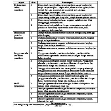
Rubrik Penilaian Keterampilan Praktikum 25606z
November 2020 0
Logo Ppni b604y
August 2021 0
Makalah Ilmu Qiraat 6f124
October 2020 0