Np100 Edition 9 2009.pdf 6w686o
This document was ed by and they confirmed that they have the permission to share it. If you are author or own the copyright of this book, please report to us by using this report form. Report 2z6p3t
Overview 5o1f4z
& View Np100 Edition 9 2009.pdf as PDF for free.
More details 6z3438
- Words: 55,368
- Pages: 102
Contents
LAWS AND REGULATIONS APPERTAINING TO NAVIGATION While, in the interests of safety of shipping, the United Kingdom Hydrographic Office makes every endeavour to include in its hydrographic publications details of the laws and regulations of all countries appertaining to navigation, it must be understood: (a) that no liability whatever will be accepted for failure to publish details of any particular law or regulation, and (b) that publication of the details of a law or regulation is solely for the safety and convenience of shipping and implies no recognition of the international validity of the law or regulation.
NP 100
Extracts from
THE MARINER’S HANDBOOK NINTH EDITION 2009
Edition 1.1 – December 2009
USING THIS DOCUMENT This Adobe Acrobat Portable Document Format (PDF) document is mainly intended to be used on–screen, although a single copy may be printed out for personal use. The document has been optimised for on–screen use by the inclusion of bookmarks. Click the bookmarks tab in Adobe Acrobat Reader to use this facility. s’ attention is drawn to the information contained within the introduction on page 11.
Contents
LIST OF CONTENTS This document contains extracts from the Mariner’s Handbook, 9th Edition (2009). Chapters, sections and paragraphs of the book which are not included in this extract are listed in blue type for information. Mariners who require this information should consult the paper publication.
Chapter 1 – The UKHO, surveying and charting
Charting Navigational information
Surveying
Data quality
1.24
Use of information received
1.25
Disclaimer
1.26
Digital products
1.27
Software
1.1 – 1.4
See NP 100
1.5
Charted depths
1.28
Scale
1.6
Use of source diagrams
1.29
Scale accuracy
1.7–1.8
CATZOC
1.30
1.9
Scale of survey
Chart datums and the accuracy of charted positions
1.10
Date of Survey
1.31
Surveying
1.32
Chart compilation
1.33
Positions from satellite navigation systems
1.34
Differential Global Positioning System (DGPS)
Methods and standards
Sounding methods 1.11
General information
1.35
Graduations on plans
1.12
Lead line
1.36
Distortion of charts
1.13
Single beam echo sounder
1.37
Ocean charting
1.14
Swathe echo sounder
1.38
Depth criteria for wrecks
1.15
LIDAR
1.16
Wire sweep or wire drag
1.17
Side–scan sonar
Fixing methods 1.18
Angles to local landmarks
1.19
Electronic position fixing
1.20
Satellite position fixing
Chapter 2 – iralty Charts General information Use of the most appropriate chart
Depths 1.21
Accuracy and quality of information
2.1
General information
2.2
Scale
Seabed
Accuracy and reliability
1.22
Nature of the seabed
2.3
Reliance on charts
1.23
Areas of mobile seabed
2.4
Assessing the reliability of a chart
2
Contents LIST OF CONTENTS
Horizontal datums on charts and satellite derived positions
Paper charts and diagrams
Charts of the iralty series
General information 2.5
Definition of a horizontal datum
2.6
Background
General information
History of datums 2.7– 2.10
See NP 100
2.31
Metric charts
2.32
Symbols and abbreviations
2.33
Primary and derived sources
2.34
International charts
2.35
International boundaries and national limits
Chart coverage
Datums in worldwide use 2.11
Adoption of WGS84
2.12
Undetermined datums
2.13
Effect of using different datums
2.14
Datum differences
2.15
Transferring positions between charts
2.16
Charts of the British Isles
2.17
Reporting differences between observed and charted positions
2.36
iralty charts
Categories of chart 2.37
New Chart (NC)
2.38
New Edition (NE)
2.39
Current editions
2.40
iralty Notices to Mariners
2.41
Describing a chart
Chart datums and GNSS 2.18
Datums used by GNSS
2.19
Relating the position of a point to WGS84
2.20
Applying corrections
2.21
Scale of chart and plotting accuracy
2.22
GPS receivers with built–in datum correction Regional datums and datums used on charts Survey accuracy in relation to positional accuracy of GNSS Differences in position caused by different methods of transformation
2.23 2.24 2.25
Foreign Government Charts 2.42
Foreign charts
2.43
Availability
2.44
Modified reproductions of foreign government charts
2.45
Australian and New Zealand charts
2.46
Canadian and United States charts
Charts for specific purposes Datums in electronic charting systems
2.47
Routeing charts
2.26
General information
2.48
Oceanic charts and plotting sheets
2.27
iralty Raster Chart System (ARCS)
2.49
Gnomonic charts
2.28
Electronic Navigational Charts (ENCs)
2.50
Ships’ Boats’ charts
2.29
Other electronic chart data
2.51
Azimuth diagrams
2.30
GPS input to ECS/ECDIS
2.52
Miscellaneous charts and diagrams
3
Contents LIST OF CONTENTS
Supply and distribution 2.53 2.54 2.55
ECDIS
iralty Distributors Orders Chart update services
2.81– 2.86
See NP 100
ENCs Selection of charts 2.56 2.57 2.58
Chart catalogues Carriage requirements Chart folios
General information
2.88– 2.97
See NP 100
iralty Vector Chart Service (AVCS)
State of charts on supply 2.59
2.87
General information
2.98
General information
2.99– 2.105
See NP 100
Upkeep of the paper chart outfit
iralty Raster Chart Service (ARCS)
Chart outfit management 2.60 2.61 2.62
Chart outfits Chart management system Paper Chart Maintenance Record
2.63 2.64
Action on receiving a chart outfit Action on notification of the publication of a New Chart or New Edition Action on receipt of a New Chart or New Edition Action on receipt of a chart additional to the outfit Action on receipt of replacement chart Action on receipt of a Weekly Edition of iralty Notices to Mariners
2.65 2.66 2.67 2.68
2.106
General information
2.107
Updating service
2.108
Format
2.109
Service levels
Chapter 3 – iralty Publications General information 3.1
Availability
3.2
Time used in iralty publications
iralty Sailing Directions
Correcting charts 2.69 2.70 2.71
General information Overlay update tracings used in updates
2.72 2.73 2.74
Previous updates Detail required Alterations
2.75 2.76
Blocks Completion of updates
General information
General information Introduction
2.78
Chart display systems
2.79
Electronic charts
2.80
Official and unofficial data
Scope
3.4
Currency
3.5
Units of measurement
Maintenance of Sailing Directions
Electronic charts and display systems
2.77
3.3
3.6
Use of Sailing Directions
3.7
New Editions
3.8
Supplements
3.9
Current editions
3.10
Amendment by Notices to Mariners
3.11
Amendment procedure
Ocean ages for the World 3.12
4
Contents
Contents LIST OF CONTENTS
Chapter 4 – Promulgation of information by and rendering of information to the UKHO
iralty Distance Tables 3.13
Contents
Promulgation of information
iralty List of Lights and Fog Signals
Navigationally significant information
3.14
Contents
3.15
Positions
4.1
General information
3.16
Amendment
4.2
3.17
New Editions
Selection of navigationally significant information
3.18
iralty Digital List of Lights
4.3
Promulgation
4.4
Information which is not navigationally significant
4.5
Sources of information
iralty List of Radio Signals 3.19
General information
3.20
Volume 1
3.21
Volume 2
3.22
Volume 3
3.23
Volume 4
3.24
Volume 5
3.25
Volume 6
3.26
Amendment
Navigational Warnings and weather information
iralty Tide Tables 3.27
Arrangement
3.28
Simplified Harmonic Method (SHM) for Windows
3.29
Accuracy
3.30
Coverage
3.31
Amendment
3.32
Tidal Stream Atlases
3.33
iralty TotalTide
3.34 3.35
4.6
Introduction
4.7
NAVAREAs
4.8
Types of Navigational Warnings
4.9
NAVAREA Warnings
4.10
Sub–Area Warnings
4.11
Coastal Warnings
4.12
Local Warnings
4.13
Language
4.14
International SafetyNET Service
4.15
NAVTEX
4.16
Updating charts for Navigational Warnings
Weather information 4.17
World Meteorological Organisation (WMO)
4.18
Offshore Shipping Forecast
4.19
Gale warnings
4.20
High seas – Atlantic Weather Bulletins and Storm Warnings
iralty EasyTide
4.21
Coastal Inshore Waters Forecast
Other tidal publications
4.22
Coastal Strong Wind Warnings
4.23
Ships’ Weather Reports
4.24
Met Office website
Publications ing celestial navigation 3.36
HM Nautical Almanac Office (HMNAO)
3.37
The Astronomical Almanac
3.38
The Nautical Almanac
3.39
Astronomical Phenomena
3.40
NavPac and Compact Data
3.41
Rapid Sight Reduction Tables for Navigation
3.42
Sight Reduction Tables for Marine Navigation
3.43
Star Finder and Identifier
iralty Notices to Mariners 4.25 – 4.26
How Notices to Mariners are promulgated
4.27
Numbering conventions
Types of Notices to Mariners
5
4.28
General information
4.29
Preliminary Notices to Mariners ((P) NM)
4.30
Temporary Notices to Mariners ((T) NM)
Contents LIST OF CONTENTS
Structure of the Weekly Edition of Notices to Mariners 4.31
Soundings
Section I – Explanatory Notes and Publications List
4.54
Echo sounder
4.55
Trace
4.56– 4.58
See NP 100
4.32
Section II – Updates to Standard Navigational Charts
4.33
Section III – Reprints of Navigational Warnings
4.34
Section IV – Amendments to iralty Sailing Directions
4.59
Lights
4.35
Section V – Amendments to iralty Lists of Lights and Fog Signals
4.60
Buoys
4.61
Beacons and daymarks
4.36
Section VI – Amendments to iralty Lists of Radio Signals
4.62
Conspicuous objects
4.63
Wrecks
Navigational marks
Maintenance of NM data 4.37
Retention of back copies
4.38
Annual Summary of iralty Notices to Mariners
4.39
Cumulative List of iralty Notices to Mariners
4.40
Tidal streams 4.64
Reporting
Port facilities 4.65
General information
Summary of periodical information
Offshore reports Reporting of information Observing and reporting hydrographic information 4.41
General remarks
4.42
Opportunities for reporting
4.66
Ocean currents
4.67
Discoloured water
4.68
Bioluminescence
4.69
Underwater volcanoes and earthquakes
4.70
Whales
4.71
Turtles in British waters
4.72
Ornithology
Obligatory reports 4.43
Requirements
4.44
Standard reporting format and procedures
Magnetic variation 4.73
Reporting
Views Other forms of report 4.45
Hydrographic Note
4.46
Information requiring corroboration
Positions
4.74
Introduction
4.75
Types of view
4.76
Panoramic views
4.77
Aerial views
4.78
Pilotage views
4.79
Portrait views
4.80
Close–up views
4.47
Charts
4.48
Geographical positions
4.49
Astronomical positions
4.50
Visual fixes
4.81
Quality and composition of views
4.51
Fixes from electronic positioning systems
4.82
Annotation
4.52
Fixes from GPS
4.83
Records
4.53
Channels and ages
4.84
Submission to UKHO
Presentation
6
Contents LIST OF CONTENTS
Chapter 5 – The Sea 5.1 – 5.11
Chapter 9 – Constraints on Navigation
See NP 100
United Nations Convention on the Law of the Sea (UNCLOS) (See NP 100 9.1) Ships’ Routeing (See NP 100 9.17) Minefields (See NP 100 9.34) Offshore renewable energy installations (OREI) (See NP 100 9.36) Submarine pipelines and cables (See NP 100 9.63) Bridges and overhead power cables (See NP 100 9.71)
Tidal streams 5.12
Information on charts
5.13
Other publications
Chapter 10 – Maritime pollution and conservation (MARPOL)
Tides
MARPOL regulations (See NP 100 10.1) Pollution of the sea (See NP 100 10.23) Conservation (See NP 100 10.28)
Chart Datum 5.14
Definition
5.15
Datums in use on charts
Chapter 11 – Navigation and Aids to Navigation
Tidal charts 5.16
Fixing the position
See NP 100
Tides in rivers and estuaries 5.17
Abnormalities
5.18 – 5.55
See NP 100
11.1
General information
11.2 – 11.3
See NP 100
Visual fixes
Chapter 6 – Ice Sea ice (See NP 100 6.1) Ice of Land Origin (See NP 100 6.13) Navigation in Ice (See NP 100 6.23) Material preparations for operations in ice (See NP100 6.36) Operations in ice (See NP 100 6.56) Effects on the body of exposure to cold (See NP 100 6.78)
11.4
Simultaneous bearings
11.5
Simultaneous bearing and distance
11.6
Running fix
11.7
Transit
11.8
Horizontal sextant angles
11.9
Vertical sextant angles
Astronomical observation General information
11.10
Radar
Chapter 7 – Meteorology General maritime meteorology (See NP 100 7.1) Weather routeing of ships (See NP 100 7.40) Weather related phenomena (See NP 100 7.42)
Chapter 8 – International Organisations International Maritime Organisation (IMO) (See NP 100 8.1) International Hydrographic Organisation (IHO) (See NP 100 8.6) International Association of Marine Aids to Navigation and Lighthouse Authorities (IALA) (See NP 100 8.13)
11.11
Fixing
11.12
Radar clearing ranges
11.13
Parallel index
11.14
Radar horizon
11.15
Quality and accuracy of radar returns
11.16
Radar image enhancement
11.17
Overhead power cables
Electronic position–fixing systems
7
11.18
General information
11.19– 11.22
See NP 100
Contents LIST OF CONTENTS
Satellite navigation systems 11.23
Global Navigation Satellite Systems (GNSS)
11.24
Current Global Navigation Satellite Systems
11.25
Proposed Global Navigation Satellite Systems
11.26
Other regional navigation systems
11.27
GNSS classification
11.28
Datum shifts in satellite navigation systems
Satellite based (SBAS)
General information
11.30– 11.35
See NP 100
Introduction
11.51– 11.57
See NP 100
Ground–based (GBAS) 11.58
Introduction
11.59– 11.60
See NP 100
Automatic Identification System (AIS)
Error sources 11.29
11.50
General information
NAVSTAR Global Positioning System (GPS)
11.61
System description
11.62
Function
11.63
Mandation
11.64
Objectives of AIS
11.36
General information
11.65
Operation
11.37
Obtaining a position
11.66
Operational guidance
11.38
Accuracy
11.67
AIS data input
11.39
Gaps in coverage
11.68
Inherent limitations of AIS
ing information
11.69 – 11.70 11.71
Target information
11.40
Differential GPS 11.41
Introduction
11.42
Principle
11.43
Broadcast of corrections
Collision avoidance 11.72
Use of AIS in collision avoidance
VTS
GLONASS 11.44
AIS in UK waters
General information
11.73
Use of AIS in ship reporting
11.74
Mandatory ship reporting systems
Aid to navigation GALILEO 11.45
General information
11.46
See NP 100
11.75
Search and rescue 11.76
COM 11.47
11.77
General information
11.78– 11.82
See NP 100
Lights
See NP 100
Augmentation systems 11.49
AIS in SAR operations
Long–range identification and tracking (LRIT)
General information
Indian Regional Navigational Satellite System (IRNSS) 11.48
AIS as an aid to navigation
Introduction
8
11.83
Sectors
11.84
Ranges
11.85
Aero lights
11.86
Obstruction lights
Contents LIST OF CONTENTS
Fog signals
Under–keel clearance
11.87
General information
11.128
Need for precise consideration
11.88
Homing on a fog signal
11.129
Under–keel Allowance
11.130
Mandated Under–keel Allowance
11.131
Calculation
Buoyage
Chapter 12 – Military Operations
General information 11.89
Use of moored marks
11.90
Pillar buoys
11.91
Avoidance
11.92
Sound signals
General information (See NP 100 12.1) Exercise areas (See NP 100 12.3) Submarines (See NP 100 12.10) Mine countermeasures (See NP 100 12.29) Other military activity at sea (See NP 100 12.33)
Chapter 13 – Commercial Operations
The IALA Maritime Buoyage System 11.93
13.1 – 13.98
Description
Other buoyage 11.94 – 11.97
See NP 100
Distress and rescue
See NP 100
General information Echo soundings
13.99
Sounders 11.98
General information
11.99
Transmission line
11.100
Velocity of sound
11.101
Adjustments to sounder
Global Maritime Distress and Safety System (GMDSS)
Checking recorded depth 11.102
Precision checking
11.103
Checking for navigational accuracy
Introduction
13.100
istration
13.101
Objectives
13.102
GMDSS Sea Areas
13.103
GMDSS equipment
13.104
Ship reporting systems
13.105
UK waters
13.106
Other sources of information
13.107– 13.159
See NP 100
False echoes 11.104
“Round–the clock” echoes
11.105
Double echoes
11.106
Multiple echoes
11.107
Other false echoes
Annexes
Interaction 11.108
Introduction
9
Annex A
Requirements for the Carriage of Charts and Publications (See NP 100)
Annex B
The International Rules for Preventing Collisions at Sea (See NP 100)
Annex C
IALA Maritime Buoyage System (See NP 100)
Annex D
Flags and Ensigns of Maritime Nations (See NP 100)
Contents LIST OF CONTENTS
Glossaries Glossary
used on iralty Charts and in associated publications (See NP 100)
Ice Glossary
commonly used in an ice environment (See NP 100)
Supplementary tables
Conversion tables for temperatures, pressures, distances and depths (See NP 100)
10
Contents
USE OF THIS DOCUMENT This document has been prepared to assist navigators by providing supplemental information concerning the use and limitations of UKHO charts and publications. The UKHO reference work in this field is NP100 – The Mariner’s Handbook (the current edition is the 9th, published 2009) and all mariners are advised to purchase and maintain an up–to–date copy on board their vessel. Much of the content of The Mariner’s Handbook is relevant to navigators of smaller vessels, but it is recognised that the presentation and language used within it is primarily aimed at professional navigators, typically operating larger merchant or naval vessels. This document draws attention to sections of The Mariner’s Handbook that are particularly relevant to the safe, effective use and interpretation of UKHO charts and publications by yachtsmen. Sections reproduced within this document retain the numbering from the published edition of The Mariner’s Handbook so that other UKHO charts and publications remain accurate. Where the included text (and the contents section on the preceding pages) refer to sections of the book which are not included here, a reference to the printed version is noted as follows: “(see NP100 x.xx)”, in blue text, where x.xx denotes the relevant paragraph number within The Mariner’s Handbook.
FURTHER READING FOR THE LEISURE READER The Mariner’s Handbook is one of a series of printed and digital publications designed to the mariner. Many are mandated by the International Maritime Organisation (IMO) for carriage aboard certain classes of vessel. Full details of the UKHO range of printed and digital products can be found in NP131 – Catalogue of iralty Charts and Publications. On–line and able PC format digital catalogues may be accessed at: www.ukho.gov.uk or www.iraltyleisure.co.uk In addition, various printed regional and leisure sector catalogues are made available from time to time. The list below highlights selected UKHO printed and digital products which may be of particular interest to the leisure . iralty iralty DP560 – Windows
Paper charts Standard navigational charts – see Chapter 2
iralty Notices to Mariners
Books for general information
Weekly Notices to Mariners – see 4.25–4.36. NP247(1) – Annual Summary of iralty Notices to Mariners Part 1 – Annual and Temporary and Preliminary Notices to Mariners – see 4.38. NP234 – Cumulative List of iralty Notices to Mariners – see 4.39. NP247(2) – Annual Summary of iralty Notices to Mariners Part 2 – Amendments to Sailing Directions – see 3.10.
Chart 5011 – Symbols and Abbreviations used on iralty Charts – see 2.32. iralty Sailing Directions – see 3.3–3.11. NP 136 – Ocean ages for the World – see 3.12. iralty List of Lights and Fog Signals – see 3.14–3.18. iralty List of Radio Signals – see 3.19–3.26. iralty Tide Tables – see 3.27–3.35. Tidal Stream Atlases – see 3.32. Publications ing celestial navigation – see 3.36–3.43.
Digital products and services iralty Raster see 2.106–2.109.
Chart
Service
(ARCS)
TotalTide – see 3.33. EasyTide – see 3.34. Simplified Harmonic Method (SHM) for – see 3.28
–
11
Contents
Chapter 1 The United Kingdom Hydrographic Office (UKHO), surveying and charting Surveying in relating the sources to the chart. Where insufficient information is available to include a source diagram, details of the source material used for the chart are given in a written summary.
Data quality Charted depths
1.5 Before using a chart to plan or navigate a age, mariners should make themselves aware of the quality of the survey data that has been used to place the soundings and contours on the chart, since not all sea areas have been surveyed to modern standards or even systematically surveyed at all. Indeed large areas of sea, especially in offshore areas, have never been systematically surveyed to any standard. The chart will have been compiled from the best data available but this does not mean that shoal areas dangerous to navigation will not exist. To help with this assessment, each chart carries a statement, below the title, referring to the origin of the data used to compile it. Where known, sources of hydrographic information are shown by means of a source diagram (see 1.6). ENCs do not carry a source diagram but instead include data fields with information about the reliability of “objects”. The object “Category of Zone of Confidence” (CATZOC) in an ENC gives an estimate of the reliability of the source data (see 1.7–1.8).
British Government Surveys a 1988 1:20 000 b 1982 - 86 1:15 000 - 1:25 000 c 1962 - 79 1:12 500 - 1:25 000 d 1968 - 81 1:50 000 e 1950 - 58 1:12 000 - 1:14 619 f 1955 - 64 1:72 000 - 1:75 000 g 1925 - 50 1:24 960 - 1:54 157
SOURCE DATA h 1878 - 81 1:145 000 - 1:365 000 (Leadline) French Government Surveys j 1976 - 81 1:20 000 k 1833 - 34 1:50 000 French Charts 1:150 000 (based mainly on l 1996 surveys of 1969 - 83)
50'
b c
g
d c e
d
c
c
a
b g
e
40'
a
e c
d
d
g
50°
d
30'
b
d
f
20'
f
d j h
10'
l k
h
l
50° 00'
40'
1°00'
20'
40'
20'
0°00'
20'
Source Diagram (1.6)
Use of source diagrams
CATZOC
1.6 The source diagrams on iralty charts and ARCS are scaled replicas of the chart, showing the coverage, dates, scales and authority for the various types of source material since these can give an indication of the quality of the survey(s) used to compile the chart, and hence the reliability of the depicted sea floor. The source diagram may also show areas of shallow banks or routeing measures to assist
1.7 CATZOC allows a hydrographic authority to encode data against five categories (ZOC A1, A2, B, C, D), with a sixth category (U) for data which has not been assessed. The categorisation of hydrographic data is based on three factors (position accuracy, depth accuracy, and sea floor coverage), as shown in the table below:
CATEGORY OF ZONES OF CONFIDENCE (ZOC TABLE) 1 ZOC1 A1
2 Position
Accuracy 2
± 5m + 5% depth p
3 Depth
Accuracy 3
0V5m + 1% depth Depth (m)
Accuracy (m)
10 30 100 1000
± 0⋅6 ± 0⋅8 ± 1⋅5 ± 10⋅5
4
5
Seafloor Coverage
Typical Survey Characteristics 5
Full area search undertaken. Si ifi Significant t seafloor fl features f t detected4 and depths measured.
12
Controlled,, systematic y surveyy 6. High g position p and dd depth th accuracy achieved hi d using i DGPS or a minimum of three high quality lines of position (LOP) and a multibeam, channel or mechanical sweep system.
Contents
1
2
3
4
5
ZOC1
Position Accuracy 2
Depth Accuracy 3
Seafloor Coverage
Typical Survey Characteristics 5
A2
B
C
± 20m
1V0m + 2% depth
± 50m
Depth (m)
Accuracy (m)
10 30 100 1000
± 1⋅2 ± 1⋅6 ± 3⋅0 ± 21⋅0
1V0m + 2% depth
± 500m
Depth (m)
Accuracy (m)
10 30 100 1000
± 1⋅2 6 ±1 1⋅6 ± 3⋅0 30 ± 21⋅0 21 0
= 2V0m + 5% depth Depth (m)
Accuracy (m)
10 30 100 1000
± 2⋅5 ± 3⋅5 ± 7⋅0 ± 52⋅0
Worse than ZOC C
Full area search undertaken. Si ifi Significant t seafloor fl features f t detected4 and depths measured.
Controlled,, systematic y surveyy 6 achieving g position iti and dd depth th accuracy lless th than ZOC A1 and using a modern survey echo sounder7 and a sonar or mechanical sweep system.
Full area search not achieved;; uncharted features, features hazardous to surface navigation are not expected, but may exist.
Controlled,, systematic y surveyy achieving g similar i il depth d th but b t lesser l position iti accuracies i than ZOC A2 using a modern survey echo sounder but no sonar or mechanical sweep system.
Full area search not achieved;; d th anomalies depth li may be b expected. t d
Low accuracyy surveyy or data collected on an opportunity t it basis b i such h as soundings di on age.
Full area search not achieved, large depth anomalies may be expected.
Poor quality data or data that cannot be quality assessed due to lack of information.
D
Worse than ZOC C
U
Unassessed – the quality of the bathymetric data has yet to be assessed.
To decide on a ZOC category, all conditions outlined in columns 2–4 of the table must be met. Footnotes 1. The allocation of a ZOC indicates that particular data meets minimum criteria for position and depth accuracy and seafloor coverage defined in this table. ZOC categories reflect a charting standard and not just a hydrographic survey standard. Depth and position accuracies specified for each ZOC category refer to the errors of the final depicted soundings and include not only survey errors but also other errors introduced in the chart production process. Data may be further qualified by Object Class ‘Quality of Data’ (M_QUAL) sub–attributes as follows: a. Positional Accuracy (POSACC) and Sounding Accuracy (SOUACC) may be used to indicate that a higher position or depth accuracy has been achieved than defined in this table (eg a survey where full sea floor coverage was not achieved could not be classified higher than ZOC B; however if the position accuracy was, for instance, ±15 m, the sub–attribute POSACC could be used to indicate this. b. Swept areas where the clearance depth is accurately known but the actual seabed depth is not accurately known may be accorded a higher ZOC (ie A1 or A2) providing positional and depth accuracies of the swept depth meets the criteria in this table. In this instance, Depth Range Value 1 (DRVAL1) may be used to specify the swept depth. The position accuracy criteria apply to the boundaries of swept areas. c. SURSTA, SUREND and TECSOU may be used to indicate the start and end dates of the survey and the technique of sounding measurement. 2. Position Accuracy of depicted soundings at 95% CI (2⋅45 Sigma) with respect to the given datum. It is the cumulative error and includes survey, transformation and digitising errors etc. Position accuracy need not be rigorously computed for ZOCs B, C and D but may be estimated based on type of equipment, calibration regime, historical accuracy etc. 3. Depth accuracy of depicted soundings = a + (b–d)/100 at 95% CI (2⋅00 sigma), where d = depth in metres, at the critical depth. Depth accuracy need not be rigorously computed for ZOCs B, C and D but may be estimated based on type of equipment, calibration regime, historical accuracy etc. 4. Significant sea floor features are defined as those rising above depicted depths by more than: Depth
Significant feature
< 40 m
2m
> 40 m
10% depth
A full sea floor search indicates that a systematic survey was conducted using detection systems, depth measurement systems, procedures, and trained personnel designed to detect and measure depths on significant sea floor features. Significant features are included on the chart as scale allows. It is impossible to guarantee that no significant feature could remain undetected, and significant features may have become present in the area since the time of the survey. 5. Typical survey characteristics. These descriptions should be seen as indicative examples only. 6. Controlled systematic surveys (ZOCs A1, A2 and B) are surveys comprising planned survey lines, on a geodetic datum which can be transformed to WGS84. 7. Modern survey echo sounder. A high precision, single beam depth measuring equipment, generally including all survey echo sounders designed post–1970.
1.8 ZOC A1 and A2 require very high accuracy standards which were rarely, if ever, achieved before the advent of satellite positioning in the 1980s. Therefore, many sea lanes which have been regarded as adequately surveyed for many years may carry a ZOC B classification. Note. The ZOC classification attained by a survey is for the survey at the date it was conducted. In areas of mobile seabed the actual seabed may differ markedly from what has been charted, even if the survey is only a few months old (see 1.23).
ZOC U. In the early days of ENC production, hydrographic authorities created ENCs by digitising the existing paper charts. Although this allowed for a rapid expansion in the numbers of ENC cells that were available, it meant that the compilers creating the ENC did not have to hand all the information required to assess which ZOC classification the different parts of the ENC should have. Rather than expend time researching this information, hydrographic authorities categorized the entire ENC as ZOC U, meaning that the category of the data had not been assessed. Although this situation is improving, it will be some
13
Contents
time before early ENC cells are revisited and have all soundings categorised with an appropriate CATZOC.
In one case, a shoal of 0⋅2 m was discovered lying between two survey lines, each of which showed depths of greater than 10 m. The scale of this survey was 1:5000, with line spacings of only 25 m. See diagram 1.9. With the advent of swathe survey systems (1.14), the surveyor became able to cover the sea floor fully. At this time, the concept of scale of survey becomes meaningless and the term ‘full sea floor coverage’ is used on source diagrams to indicate that this is the case. Where a swathe system has been used, but there are concerns that it may not have detected all objects (ie there are small gaps in the coverage), or a bathymetric LIDAR system (1.15) has been used, the source diagram will be annotated ‘partial sea floor coverage’.
Scale of survey
1.9 The scale is the scale of the survey fair sheet provided by the surveyor to the UKHO. This only had any real relevance where the survey covered the fair sheet with no gaps. For almost all surveys conducted before 1865, and inshore surveys conducted before 1905, the quoted scale has no particular relevance since the surveyor would not have covered his plotting sheet fully. Between 1905 and 2000, the scale provides an indication of the line spacing between soundings. Surveys were generally plotted so that the survey lines were 5 mm apart on the plotting sheet. Thus a survey with a scale of 1:12 500 would have lines run at 62⋅5 m intervals. The scale for a survey was generally selected so that it would detect changes in the sea floor topography that were expected in the area: for example, in areas where rock pinnacles were expected, a larger scale survey (and hence narrower line spacings) would be chosen in comparison to flat sandy areas. It should be noted that for surveys conducted before side–scan sonar (1.17) became available, dangers to shipping could still exist between the lines. For a single beam echo sounder survey conducted at a line spacing of 62⋅5 m, a wreck the size of a large tanker could remain undetected if it lay parallel to and between two adjacent lines. Recently, there have been several instances of uncharted shoals being found in areas where comprehensive surveys, up to scales of 1:5000, had been carried out, but before side scan technology was available.
Date of survey
1.10 Over time, the technology available to conduct hydrographic surveys has improved and this has allowed the surveyor to survey areas with greater accuracy and certainty. New technology tends to remain in use for relatively long periods of time before a further advance is introduced which may enable a step change in capability. Following such a step change, this further improvement in capability is also likely to remain relatively stable for a significant period. This means that there have been several “technology horizons”, the dates of which are a useful indication of the surveying accuracy likely to have been achieved, although these dates can only be approximate due to the time taken to phase in new technology. The following table shows significant dates on the technology horizon:
"Undetected danger"
"Undetected danger"
E
D
10.0m
62.5m
62.5m
a
a
b
c
b Section through DE
c
l l l l l l 105 101 103
103
102 101 103 Soundings recorded on survey at scale of 1: 12,500
D
98
98
97
98
96
95
95
95
95
92 l l
92 l l
91 l l
a
b
10
98
E
D Undetected dangers
c
Dangers between lines of soundings (1.9)
14
+ +
95
95
92
E
Appearance of corresponding portion of chart on same scale.
Contents
Date
Sounding Method
Fixing Method
Remarks
Pre– 1865
lead line
Angles to local landmarks
Surveys were mainly concerned with recording previously undiscovered land. More attention was given to fixing the coast than to provide soundings. Soundings, where present at all, tend to be sparse, with irregular gaps between them. The quoted scale is largely irrelevant when used to judge sounding density.
1865
lead line
Angles to local landmarks
Steam replaced sail in British survey ships and regular lines of soundings begin to appear. Offshore, the scale of the survey will give an indication of the expected density of soundings. Inshore, where boats were used instead of ships, oars remained the method of propulsion, and sounding lines continued to be irregular.
1905
lead line
Angles to local landmarks
Steam replaced oars as the propulsion method for survey boats, allowing regular lines of soundings to be extended to all areas of the survey. The scale of the survey gives an indication for the first time of the expected density of soundings.
1935
single beam echo sounder Angles to local landmarks
Greater ease of collecting soundings allowed far denser surveys to be gathered. The scale of the survey gives an indication of the expected density of soundings.
1950
single beam echo sounder Electronic position–fixing
Greater accuracy and consistency of position fixing extending farther offshore than was possible with angles to shore marks.
1973
single beam echo sounder Electronic and side–scan sonar position–fixing
Side–scan sonar allows surveyor to locate hazards that exist between lines of soundings. For the first time, surveys will have covered the entire sea floor.
1985
single beam echo sounder Satellite and side–scan sonar position–fixing
Introduction of satellite positioning allows surveyor to accurately position his ship anywhere in the world to a common datum.
2000
Swathe echo sounder
Swathe systems replace single beam echo sounders and side–scan sonar. Swathe systems permit the surveyor to detect obstructions between survey lines and to gather depths over them.
Satellite position–fixing
It should be noted that the date when a survey was conducted is of particular relevance in area where the seabed is composed of unstable materials and is therefore liable to move. The maximum draught of vessels in service at the time of a survey affected the depths to which soundings were taken, and the depths of shoals examined. Until 1858, the year in which the SS Great Eastern, with an intended draught of 9⋅1 m, was launched, the draught of a vessel rarely exceeded 6 m. Draughts of 15 m were considered a maximum until about 1958. Now, the largest vessels in service may have draughts of up to around 30 m. In spite of the advances in modern surveying methods, and the many reports received from vessels at sea, undiscovered dangers, particularly to deep–draught vessels, must still be expected, even on well–frequented routes. For example, Walter Shoals, on the route from Cape of Good Hope to Selat Sunda, with a least depth of 18 m, were not discovered until 1962.
An illustration of the data quality obtainable by some of these sounding methods can be seen in the examples of sandwaves (see NP 100 5.53).
Lead line
1.12 This is the oldest method of obtaining depth information. The surveyor lowers a lead weight, into the sea, attached to a graduated line. When the weight touches the bottom, the depth is recorded using the graduations on the line. The method is simple, and can be highly accurate. The problem with using a lead line is that it only measures the depth in the position where the line is lowered and gives no information about depths in other areas.
Single beam echo sounder
1.13 The single beam echo sounder transmits a pulse of acoustic energy vertically below the vessel and times the interval between transmission and reception of the returning echo. Provided that the speed of sound in the water column is known, the time interval can be used to calculate the depth of water. Vessels equipped with a single beam echo sounder are able to gather a complete profile off the sea floor directly beneath them. The depths along this profile are generally of high accuracy, although, like the lead line, single beam echo sounders provide no information about depths either side of the vessel’s track.
Sounding methods General information
1.11 There are four sounding methods used to obtain depth data for use on iralty charts: lead line, single beam echo sounder, swathe echo sounder, and LIDAR (Llght Detection And Ranging) (see 1.15). Additionally, Wire Sweep and Sidescan sonar are included here, for although they are not sounding methods in themselves, they aid the surveyor in providing a better understanding of the seabed and associated depths.
Swathe echo sounder
1.14 There are two types of swathe echo sounders, interferometric and beam–forming. Although the technologies are different, the result of their use in
15
Contents
U n s u r v e y e d
Unsurveyed
38
38
37 38
38 38
Lead Line
Lead Line sounding selection
Sounding Methods (1.11)
16
Contents
38
30 29
37
38 33
38
Single Beam
Single Beam sounding selection
38 36 27 38 30
295
38
35 235 Wk
38
Multibeam
Multibeam sounding selection
Sounding Methods (1.11)
17
Contents
surveying is similar, so they are considered together here. Swathe echo sounders transmit a swathe of acoustic energy along a narrow fan ahead and astern, and in a wider fan on either beam. The reflected energy from the sea floor is processed and the position for each depth, relative to the transducer, is computed from the angle of reception and the time. The major benefit of swathe echo sounding is that close to 100% coverage of the sea floor can be achieved, so that uncertainties between adjacent sounding lines can be greatly minimised. In addition, the acoustic processing technology used in swathe echo sounding equipment results in a much higher resolution of sea floor features, resulting in a much better understanding of the seabed topography. See also 11.102.
exceptionally clear water, the maximum depth is about 70 m, whereas typically in UK waters 20–30 m is the maximum achievable penetration. Black rocks and kelp will also further limit the maximum effective depth of the system. The foregoing constraints can combine to make the system less able to produce high–resolution sea floor mapping than than a swathe system, although it is still substantially better than a single beam echo sounder survey. Nevertheless, being aircraft mounted, LIDAR is useful for surveying shallow areas which it is difficult for boats to reach. Also, aircraft speeds allow large areas to be covered (up to 65 km2 per hour) much more quickly.
Wire sweep or wire drag
1.16 Depths obtained from wire sweeps appear on iralty charts, notably over wrecks. When a wreck is discovered, it may not be possible to obtain an accurate depth using a single beam echo sounder, because some narrow or thin features such as masts or derricks may represent a danger but do not necessarily on the sounder. In order to establish the presence of such dangers, the survey vessel will lower a thin wire to a predetermined depth and slowly traverse the position of the wreck. If the wire does not snag, it is lowered in stages and the process is repeated until it does. The deepest depth at which the wire did not snag is then recorded as the “swept” depth.
LIDAR
1.15 LIDAR is a laser pulsing device, normally mounted in fixed or rotary–wing aircraft, which uses timed pulses of energy to measure the distance between the transmitter and the ground or sea floor. There are two types in use: topographic and bathymetric. Information from both may exist on iralty charts. Topographic LIDAR. As the name implies, topographic equipment can only be used to measure heights of land, but if used at low water, can provide useful information on drying sandbanks. The equipment uses a low power infra–red laser that can be pulsed very quickly (10 kHz) and has a very narrow beamwidth, allowing highly detailed data to be collected. The density of the data results in surveys that are normally as good or better than the highest quality swathe echo sounder surveys. The infra–red laser used in these systems will not penetrate any water, so any survey carried out can only take place when the sea floor is dry. Bathymetric LIDAR. This equipment works in a similar way to topographic LIDAR except that in order for the laser pulse to penetrate the water, it uses a blue–green laser. Also, because of the greater difficulty in penetrating water, more power is required. This creates two problems: firstly, because the greater power output generates more heat, the laser cannot be pulsed as quickly (1 kHz is the more common speed, but there are some which operate around 3 kHz). Secondly, The wavelength and power of the pulse must be diffused in order to make it eye safe. For these reasons, the laser has a spot diameter of about 2 m when it hits the sea surface, much broader than the narrow beam of the infra–red laser. Refraction within the water column also affects the spot diameter, so that it expands to around half the water depth; for example in 20 m of water, the spot diameter of the pulse will be in the order of 10 m. This limits the ability of system to detect small features, and it is therefore not possible to say with any certainty that small features (up to around : of the area of the spot) have been detected. Furthermore, because LIDAR works by effectively shining light through water, the opacity of the water limits the depth to which the laser can penetrate. In
Side–scan sonar
1.17 Side–scan sonar is not used for obtaining depths. It is, however, a tool which can look sideways and allows the surveyor to detect the presence of features either side of the vessel’s track. Once detected, the surveyor must run extra sounding lines over the detected feature in order to obtain its depth.
Fixing methods Angles to local landmarks
1.18 Before satellite or electronic position fixing systems were available, surveyors would position their boats by measuring angles to prominent local landmarks. If done carefully, this can be a very accurate method, although it only positions the boat relative to the local landmark.
Electronic position fixing
1.19 In the 1950s, electronic position fixing became available. The first such systems used three or more land–based transmitting stations which allowed the surveyor to position himself using special charts drawn up with lattices overlaid on the charted detail. This method of fixing was not necessarily more accurate than the angles used earlier, but it did have the advantage that it worked farther offshore, and in all weather conditions.
Satellite position fixing
1.20 With the advent of satellite positioning, the surveyor became independent of shore stations for the first time, because satellite derived positions were related
18
Contents
to a global horizontal datum eg WGS84. Initially, the accuracy of these systems were no greater than those derived from electronic position fixing, but they had the advantage of being able to be used worldwide. The disadvantage was that for the first time the relationship between the global horizontal datum in use and local land datums, to which all previous surveys had been related, had to be defined. Sometimes the difference could be in the order of several hundred metres. This problem was resolved by converting positions from one datum to the other before plotting. Recently, advances in processing methods have led to a significant increase in the accuracy obtainable from satellite positioning systems, and surveys can now be positioned with an accuracy of better than 5 m. On charts based on older surveys, it may therefore be expected that some dangers within the 20 m depth contour may have been missed, and that even when the survey is modern every danger may not have been located.
isolated soundings appreciably shoaler than surrounding ones, as some rocks are so sharp that the shoalest part may not have been found by the lead, or the echo sounder may not have ed directly over the peak. Depths over wrecks (1.38) should be treated with caution for the same reason, unless they have been obtained by wire sweep. Soundings which do not originate from a regular survey are shown as “Reported” on iralty charts, or “Doubtful” on International charts. They may prove to be incorrect in depth or position, or totally false. In the case of a newly-discovered feature it is unlikely that the least depth will have been found. Such soundings should therefore be taken to indicate that similar, or less depths, may be encountered in the vicinity.
Seabed Nature of the seabed
1.22 Too much trust should not be placed on the quality of the seabed shown on charts, since the majority of samples will have been obtained by means of a lead armed with tallow, and are therefore only representative of the surface layer. More reliable are seabed symbols shown in the vicinity of anchorages, or qualities of the seabed described with the holding ground in iralty Sailing Directions, as the samples will probably have been obtained from the anchor flukes of the vessel that did the original survey. More reliance can also be placed on symbols showing one type of seabed over another, as the sample must have been larger than that usually obtained from an armed lead.
Depths Accuracy and quality of information
1.21 Outside the 20 m depth contour there may be known shoal depths which were not significant when they were found, but which, if fully examined. could prove to be dangers with less water than charted over them. Offshore surveys seldom attain the precision of those in sheltered inshore waters due to difficulties in fixing, in sounding in a seaway, and the almost invariable requirement to reduce soundings to chart datum using interpolation between distant tide gauges. Due caution should therefore be exercised when in parts of the world which have not been recently surveyed or where isolated pinnacles or shoals are common. Deep draught vessels in particular should exercise due caution when within the 200 m depth contour in parts of the world which are imperfectly surveyed, or where many reported shoals are shown on the charts. Within the 20 m depth contour, for the same reason, it must be assumed that some dangers may not have been detected. Vessels of normal draught should not therefore approach the shore within the 20 m depth contour without taking due precaution to avoid a possible danger. Outside the 20 m depth contour there may be not only similar dangers, but others discovered by older surveys, but not then being significant to shipping on of their depths, not examined to modern standards. Even with plans of harbours and channels which have been surveyed in detail on scale of 1:12 500 or larger, vessels should avoid if possible ing over
Areas of mobile seabed
1.23 In certain areas where the nature of the seabed is unstable, depths may change by several metres in a matter of weeks. In these cases, even when surveys are conducted to a modern standard (i.e. 1973 onwards), if the seabed is mobile, significant differences may still exist between depths as charted and depths as they presently exist. In areas where the seabed is very changeable, the chart will carry a legend such as “Changeable Depths”. In such areas, the mariner should exercise due caution and obtain the latest known depths from local authorities, even when the charted depths along the intended track indicate sufficient depth of water, proceeding only when safe to do so. Coral reefs (see NP 100 5.46) can grow by as much as 0·05 m in a year, or 5 m in a century. Shifting banks or sandwaves (see NP 100 5.53) may themselves appreciably alter depths, or may move or uncover wrecks near them.
19
Contents
Charting The most obvious case is the supply of software for tidal prediction, such as iralty TotalTide (3.33). In other cases, search facilities are incorporated in products to enable the to locate particular items of information. The UKHO normally commissions the development of such software and all possible means are used to ensure that the information generated within such a product is correct and reliable. However, with increasingly complex software, it is important that the should only operate it on suitable equipment, as stated in the individual guidance notes for the product. It is also important that other applications should not be running on the ’s machine at the same time. Guidance notes and advice relating to software and data are included with the product information for each individual product.
Navigational information Use of information received
1.24 Increased offshore operations and interest in the sea floor, the continuous development and construction of ports and terminals, the deeper draught of vessels using coastal waters, increased traffic management, and more efficient and rapid methods of surveying, are among the reasons for the growing amount of information reaching the UKHO. This information is closely examined on receipt before being promulgated in the wide range of paper and electronic charts, diagrams, books, pamphlets and digital products published by the UKHO. In this way it is sought to keep hydrographic products up-to-date.
Methods and standards
Disclaimer
1.25 While the UKHO makes all reasonable efforts to ensure that data supplied is accurate, it should be appreciated that the data may not always be complete, up–to–date or positioned to modern surveying standards and therefore no warranty can be given as to its accuracy. The mariner must be the final judge of the reliance he places on the information given, bearing in mind his particular circumstances, the need for safe and prudent navigation, local pilotage guidance and the judicious use of available navigational aids. The appearance and content of the data depicted on paper and digital charts may vary with the scale of the chart and may be different when depicted in a digital chart system (see 2.87).
Scale
1.26 Increasing use is being made of new digital techniques for displaying, transmitting, and updating navigational information used at sea. Digital data products include electronic charts (2.87), iralty TotalTide (3.33), the iralty Digital List of Lights (3.18), and services such as iralty Notices to Mariners (4.25) to be found on the UKHO website www.ukho.gov.uk Within the UKHO, strenuous efforts are made to ensure that the data provided through these services are as accurate as they can be. Data received on CD–ROM will have been checked before issue. Data on the web is checked before posting to the website and regular checks of the data on the website are maintained. There remains a small risk that such data may be corrupted by hitherto unforeseen means or even by the ’s own digital equipment.
1.28 The nature and importance of the area concerned govern the thoroughness with which the area must be examined and therefore the selection of the scale of the survey. Ports and harbours are usually surveyed on a scale of between 1:12 500 and 1:5000, and anchorages on a scale of only 1:25 000. A general survey of a coast which vessels only in proceeding from one place to another is seldom made on a scale larger than 1:50 000. In such general surveys of coasts or little frequented anchorages, the surveyor does not contemplate that ships will approach the shore without taking special precautions. Survey systems which collect data in a digital form, and multibeam echo sounders which can achieve total ensonification of the sea floor, do not themselves guarantee complete and rigorous coverage of an area. The method by which the data obtained is processed is particularly important in assessing the completeness of coverage and is therefore carefully considered by the chart compiler before eliminating any pre–existing shoal depths. Charts may be published on a smaller scale than the surveys on which they are based, though modern large scale charts are often published on the same scale as the original surveys. With an older chart it would be unwise to assume the original survey was on a larger scale than that of the chart itself. Very rarely is it necessary for the scale of any part of a chart to be larger than the scale of the survey: if such extrapolation has been necessary the fact is stated in the title block of the chart to warn against the false sense of accuracy such extrapolation gives.
Software
Scale accuracy
Digital products
1.27 In addition to the increasing supply of digital navigational information, the UKHO is finding the need to develop products which embody software which generates data and information for use in navigation.
1.29 The accuracy of the scale of a chart depends on the accuracy of the original base measurement and early surveys in difficult terrain often used methods that were less accurate than modern electronic means.
20
Contents
This resulted in small unknown errors in scale and therefore distances throughout the survey, which should be borne in mind when fixing by radar in remote areas. For example, whilst an error of 5% in the length of the base would have no practical effect on fixes based on bearings or angles, distances obtained by radar would need to be adjusted by 5% to agree with charted distances. Positions plotted on, or extracted from, a chart will contain an element of imprecision related to the scale of the chart. Examples: At a scale of 1:600 000, a chart who is capable of plotting to a precision of 0·3 mm must appreciate that this represents approximately 120 m on the ground. At a scale of 1:25 000, the same plotting error will be only about 5 m on the ground. Thus, if the difference between a WGS84 Datum position and the horizontal datum of the chart is, say 50 m, this would not be plottable at the smaller scale, (the chart could effectively be said to be on WGS84 Datum) but would be plottable (2·0 mm), and therefore significant, at the larger scale. This explains why it is not uncommon for small and medium scale approach charts to be referenced to WGS84 Datum while the larger scale port plans have no quoted horizontal datum. Similarly, some charts at scales of 1:50 000 and smaller just quote a reference to WGS Datum (without a year date) since the positional difference between WGS72 and WGS84 Datums is not plottable at these scales.
Geographical Position
Horizontal Datum
51°08′⋅47N 1°22′⋅35E
Referred to European (1950) Datum (the Continental datum)
51°08′⋅42N 1°22′⋅27E
Referred to World Geodetic System 1984 (WGS84) Datum (the world–wide datum used by Global Positioning System (GPS))
Most paper charts world–wide are not yet referred to WGS84 Datum. This means that, in those cases, positions obtained from satellite navigation receivers will not be directly compatible with the chart and must not be used without adjustment. Hydrographic offices are attempting to refer as many new charts as possible to WGS84, but there remain many areas of the world where information does not exist to enable the transformation to be performed. When known, the horizontal datum of the chart is usually named in the chart title block although, on its own, this information is of limited benefit to the mariner. Since 1982 many hydrographic offices have been adding “Satellite–Derived Positions” notes (usually situated close to the title) when charts have been revised. This note provides a latitude and longitude adjustment to be applied to positions obtained directly from satellite navigation systems (such as GPS) to make them compatible with the horizontal datum of the chart. The following provides a worked example: Satellite–derived position Lat/Long adjustments Adjusted position (compatible with Chart Datum)
Chart Datums and the accuracy of charted positions
1.30 The International Maritime Organization offers the following advice:
The practical result is that a given geographical position, not associated with a specific datum, could refer to different physical objects. In other words, a physical object can have as many geographical positions as there are datums. For example, South Foreland Lighthouse, United Kingdom, has the following positions: 51°08′⋅39N 1°22′⋅37E
21°30′⋅00W
0′⋅07S
0′⋅24E
4°21′⋅93N
21°29′⋅76W
In this example, the shift equates to approximately 230 m which can be plotted at scales larger than 1:1 000 000. Where known, these adjustments are an average value for the whole area covered by the chart and are quoted to 2 decimal places of a minute in both latitude and longitude, so that the maximum uncertainty is about 10 m in both latitude and longitude (0⋅005′ and 0⋅014′ will both be rounded to 0⋅01′). This uncertainty can be plotted at scales larger than 1:30 000 (where it is represented by 0⋅3 mm on the chart). Inevitably, cases exist where overlapping charts show different latitude or longitude shift values. For example, one chart might show 0 ⋅ 06′ and its neighbour 0⋅07′; for each individual chart the value will be an average, but in the area common to both charts the value will range from 0⋅064′ to 0⋅066′. In cases where an adjustment cannot be determined because of the lack of knowledge about the relationship between WGS84 Datum and the datum of the chart, the hydrographic office may add a note to that effect, warning that adjustments “may be significant to navigation”. The largest difference between satellite navigation derived and charted position reported so far is 7 miles in the Pacific Ocean, but even larger undiscovered differences may exist. Where charts do not contain any note about position
“Many different definitions of a horizontal datum (also known as geodetic datum) exist. However, a practical working definition in use is: A horizontal datum is a reference system for specifying positions on the Earth’s surface. Each datum is associated with a particular reference spheroid that can be different in size, orientation and relative position from the spheroids associated with other horizontal datums. Positions referred to different datums can differ by several hundred metres.”
Geographical Position
4°22′⋅00N
Horizontal Datum Referred to OSGB(36) Datum (the former local datum for the United Kingdom)
21
Contents
adjustment it must not be assumed that no adjustment is required. Most manufacturers of GPS receivers are now incorporating datum transformations into their software which enable s to (apparently) receive positions referred to datums other than WGS84 Datum. Unfortunately, many cases exist where a single transformation will not be accurate for a large regional datum. For example, the relationship between WGS84 Datum and European Datum (1950) is very different between the north and south of the region, despite the datum name being the same. Therefore, the position transformed to WGS84 Datum in the receiver by means of a Europe–wide average may differ from the WGS84 Datum position output by the receiver, amended to European Datum (1950) by the shift note on an individual chart. This is a source of error and may be of major significance for navigation. It must not be assumed that all charts in a region are referred to the regional datum. For example, although most metric charts of mainland European waters are referred to European Datum (1950), many charts are also referred to local datums, such as Norwegian Datum 1948. Additionally, as there are no international standards defining the conversion parameters between different horizontal datums, the parameters used by the GPS devices may be different. Hydrographic offices use the best available parameters, so mariners are advised to keep their GPS receiver referred to WGS84 Datum, or, in the case of GLONASS to PZ90 Datum, and apply the datum adjustment note from the chart. Apart from the differences in positions between different horizontal datums, two other aspects affect charted positional accuracy. These aspects are: The accuracy to which features are surveyed (see 1.31). The accuracy to which they are compiled on to a chart (see 1.32).
capacity to enable the observations to be analysed to enable an estimate of the accuracy of position fixing to be generated. The result is that, although the current accuracy standard of position fixing surveys can be stated, it is impossible to provide anything other than general estimates for older surveys. The current accuracy standard for positioning is "13 metres for most surveys with the standard of plus or minus 5 metres (both 95% of the time) for certain special purpose surveys. It can be confidently stated that the former value is often significantly improved upon. Further improvements will undoubtedly be made as a result of technological developments, but at present there has to be a balance between the cost of a survey and the quality and quantity of the results achieved. In summary, although the position of maritime objects derived from modern surveys will be accurate to better than 10 metres, this cannot be used as a general statement about all such objects.
Chart compilation
1.32 Most paper charts and their derived digital versions are assembled from a variety of sources such as maps, surveys, and photogrammetric plots. The intention is to provide the mariner with the best available information for all parts of that chart and the usual procedure is to start with the most accurate sources, but it is often impossible to complete the whole chart without recourse to older, less accurate, sources. When sources are referred to different datums, transformations have to be calculated and applied to make the sources compatible. The intention is for such transformations to have an accuracy of 0⋅3 mm at chart scale, this being the effective limit of manual cartography. But, depending on the information available, this may not always be possible. When the positions of navigationally significant objects are accurately known, the intention is that they are located on a chart to an accuracy of 0⋅3 mm. The obvious consequence is that accuracy varies with chart scale. Thus: 0⋅3 mm at a scale of 1:10 000 is 3 m; 0⋅3 mm at a scale of 1:50 000 is 15 m; 0⋅3 mm at a scale of 1:150 000 is 45 m. The situation will change as chart data becomes available digitally, but much of the early digital data will derive from these paper charts and the limitations will remain. Furthermore, a pixel on a computer display screen is approximately 0⋅2 mm square, roughly equivalent to the accuracy available on the paper chart. The situation for mariners is improving with recent surveys referred directly to WGS84 Datum, increasing numbers of charts referred to WGS84 Datum (or to ETRS89 or other WGS84 compatible datums) which for all practical purposes is the same) and increased international co–operation in the exchange of information. It will be many years before all areas are re–surveyed and all charts revised. Until such time, mariners should remain alert to danger. A satellite navigation receiver may output a position to a precision of three decimal places of a minute, but that does not mean that all its positions are accurate to 2 m or that the resulting position is
Surveying
1.31 Hydrographic surveys are generally conducted using the best position–fixing technology available at the time. Until the Second World War, this was limited to accurate visual fixing. Subsequently, terrestrial based electronic position fixing (such as Decca, Hifix, Hyperfix, and Trisponder) were used until the 1980s. DGPS is the current standard for most hydrographic surveys. Generally, position fixing for surveying was more accurate than that for navigation in the first two categories, but DGPS (1.34 and 11.41) is widely available for use by all mariners with the appropriate equipment. The result is that current navigation with DGPS is, commonly, more accurate than position–fixing used for surveys conducted before 1980. The consequence is that, although a modern vessel may know its position to an accuracy of better than 10 metres, the position of objects on the sea floor may only be known to an accuracy of 200 metres or much worse, depending on the age of the latest survey and/or its distance from the coast. Furthermore, it is only since the 1980s that surveying systems have had the computer processing
22
Contents
compatible with the positions of objects shown on modern charts (paper or digital) which may have been established 100 years ago and not surveyed since. The chart title notes and cautions and the source diagram, which shows the ages of surveys, must always be consulted for indications of limitations.
datums. These factors may each introduce apparent inaccuracies between the chart and the GPS if the mariner relies solely on GPS for navigation and attempts to navigate to the quoted GPS accuracy. Mariners are warned against over reliance on the quoted accuracy of GNSS systems when using some large and medium scale iralty charts, both paper and ARCS (2.106) versions, particularly when closing the coast or approaching off lying dangers such as wrecks. In many parts of the world, including some parts of the British Isles, the most recent data available may have been gathered when survey methods were less sophisticated than they are now and the sort of accuracy currently available with GPS was not possible. In these cases, the absolute accuracy of the positioning of this data to modern standards is doubtful. However, where recent survey data exists (in most significant ports and their approaches and in other areas where modern surveys are indicated in the Source Diagram on the appropriate chart) this should be less of a problem.
Positions from satellite navigation systems
1.33 Positions obtained from GPS (11.36) are normally referred to WGS84, whilst positions obtained from GLONASS (11.44) are referred to SGS90 or PZ90, whose agreement with WGS84 Datum is less than 15 m with a mean average of about 5 metres. As a result, at present, neither can be plotted on those iralty paper charts (currently almost half the total) which are referred to local horizontal datums. The intention is to refer all charts to WGS84 Datum, but this will be a lengthy process, and one that can proceed only when the relationships between existing surveys and WGS84 Datum have been established. In advance of achieving this aim, all New Charts and New Editions of charts on scales of 1:2 000 000 and larger, published since 1981, carry a note indicating the magnitude and direction of the shift between satellite–derived positions (referred to WGS84 Datum) and chart positions. The latest wording of the shift note includes an example, unique for each chart, which depicts how the shift should be applied. There remain many charts, some carrying a note stating that a satellite–derived position shift cannot be determined, where sufficient details of horizontal datum are not known. It is important to note that in the worst cases, such as isolated islands or charts of great antiquity, there may be a discrepancy of several miles in charted positions from those derived from GNSS. This means that approximately 1000 charts carry a note which, in its latest wording, states that: “Mariners are warned that these differences MAY BE SIGNIFICANT TO NAVIGATION and are therefore advised to use alternative sources of positional information, particularly when closing the shore or navigating in the vicinity of dangers”. However, the absence of such notes must not be taken to imply that WGS84 Datum positions can be plotted directly on a chart, simply that the chart has not been examined and updated since 1981. Mariners who visit areas where the charts carry no note, or have the note stating that differences cannot be determined, are requested to report observed differences between positions referenced to chart graticule and those from GPS, referenced to WGS84 Datum using Form H102b (see 4.52). The results of these observations are examined and may provide evidence for notes detailing approximate differences between WGS84 Datum and the datum of the chart.
Graduations on plans
1.35 Graduations are now inserted on all plans, and on all previously published ungraduated ones as opportunity offers. On old plans, these graduations are often based on imperfect information. Consequently, whenever an accurate geographical position is quoted, it is necessary to quote the number of the chart from which the position has been derived.
Distortion of charts
1.36 The paper on which charts are printed is subject to distortion, but the effect of this is seldom sufficient to affect navigation. It must not however be expected that accurate series of angles taken to different points will always exactly agree when carefully plotted on the chart, especially if the lines are to be objects at some distance.
Ocean charting
1.37 While most charts of the continental shelf are based on surveys of varying age and quality, very little survey work of a systematic nature has been carried out beyond the edge of the continental shelf (200 m depth contour). With the completion of the two series of International Charts on scales of 1:3 500 000 and 1:10 000 000, augmented by the series of iralty 1:3 500 000 mid–ocean charts and 1:10 000 000 Southern Ocean charts, the oceans have been systematically charted for the first time to common specifications. These charts, however, still represent only a “best guess” in their portrayal of the depths and shape of the ocean floor. They are for the most part still based on sparse and inadequate sounding data, and many significant bathymetric features, including shoals, have doubtless still to be found and charted. The International Hydrographic Organization estimated in 1976 that for only 16% of the oceans was there sufficient sounding data to determine the sea floor topography with reasonable accuracy; for a further 22% the data were only sufficient for showing major sea floor features; while for the remaining 62%
Differential Global Positioning System (DGPS)
1.34 Whereas GPS produces a quoted accuracy in the order of metres, DGPS has the potential to produce positions accurate to less than a metre when referred to WGS84 Datum. iralty charts are compiled from the best source data available, but these sources are of varying age and scale. Also, in different parts of the world, charts are referred to a variety of different
23
Contents
the sounding data were considered too sparse to describe the sea floor with any degree of completeness. Despite more lines of ocean soundings from ships on age since then, the situation is much the same today. Nearly all ocean soundings available are from random lines of soundings from a wide variety of sources of varying reliability and accuracy. Sounding coverage is best along well–frequented routes, but even in these waters undiscovered dangers may still exist, especially for deep–draught vessels. For example, the existence of Muirfield Seamount which lies on the route from Cape of Good Hope to Selat Sunda, 75 miles SW of Cocos Islands, was not suspected until 1973 when MV Muirfield reported having struck an “obstruction” and sustained considerable damage to her keel. At the time, she was travelling at 13½ kn, with a draught of 16 m in a 2 to 3 m swell, and in charted depths of over 5000 m. A subsequent survey by HMAS Moresby in 1983 found a least depth of 18 m over the seamount, the summit being level and about 5 cables in extent rising sharply on all sides from deep water. Particular care is needed when navigating in the vicinity of oceanic dangers or seamounts as very few of these features have been fully surveyed to modern standards to determine their correct position, full extent, or the least depth over them. Many charted ocean dangers and shoals are from old sketch surveys and reports, often dating from the nineteenth century. Positions from such reports may be grossly in error; their probable positional error, if prior to the general introduction of radio time signals for shipping in the 1920s, is considered to be of the order of "10–20 miles, but may be greater. Furthermore, many ocean dangers are pinnacle–shaped pillars of rock or coral rising steeply from deep water, crowning the summits of seamounts and ocean ridges: little or no warning is given from soundings in their approach. Consequently the detection of dangerous pinnacles in time to take avoiding action will be extremely difficult, especially for modern deep–draught ocean–going vessels travelling under normal conditions. A dangerous pinnacle in ocean depths could possibly exist 2 cables from depths of 1000 m, 5 cables from depths of 2000 m, and 2 miles from depths of 3000 m.
UKHO and other hydrographic offices and, furthermore, that the different hydrographic organisations may use different criteria to differentiate between these two classifications of wreck. The depth criteria used by the UKHO to differentiate between the two classifications of wreck have changed over the years. If the depth of water over a wreck was thought to be equal to, or less than, the depth criteria in the table below, then the wreck would have been charted as dangerous (e). Date
Depth criteria
Before 1960
14⋅6 m (8 fathoms)
1960 – 1963
18⋅3 m (10 fathoms)
1963 – 1968
20⋅1 m (11 fathoms)
1968 onwards
28⋅0 m (15 fathoms)
The progressive changes above were a reflection of the ever increasing sizes of vessel which were entering service during the period. Mariners should be aware, however, that circumstances exist which result in wrecks with a depth of less than 28 m over them being charted as non–dangerous wrecks (less–dangerous wrecks might be a more appropriate term) on present day editions of iralty charts. Such circumstances include: iralty charts which have been compiled either partially or entirely using data from a foreign chart where different criteria have been used for wreck assessment. In such cases the foreign criteria, and the associated chart symbols, will be carried forward on to the iralty chart. Similarly, a foreign government Notice to Mariners may promulgate information concerning a wreck in an area covered by an iralty chart. If the UKHO decides that it is appropriate to re–issue the information in an iralty Notice to Mariners for the iralty chart(s) concerned, the original foreign government criteria, assessment and resulting chart symbol will be retained. Earlier wrecks, originally assessed and charted with reference to the criteria of the day, may be charted on subsequent New Editions and New Charts without the benefit of present day re–assessment and, in consequence, will retain the symbol appropriate to the criteria of the time. An extreme example might be a 1959 wreck with a depth of 15⋅5 m (8½ fathoms) over it, which was assessed and charted as non–dangerous at the time, continuing to be charted as non–dangerous today. Wrecks with less than 28 m over them may, in certain circumstances, be assessed by the UKHO using more subjective criteria in addition to depth, and, as a result, be classified and charted as non–dangerous. In light of the foregoing, mariners are advised that wrecks charted as non–dangerous nevertheless remain worthy of caution, and that a value for the minimum depth over them cannot be derived simply by inspection of the chart.
Depth criteria for wrecks
1.38 Modern charting standards specify that new wrecks will be charted showing the least depth over them, if known. Depicting wrecks in this manner, in preference to the use of the symbols for dangerous (e) and non–dangerous (s) wrecks, provides the mariner with the maximum useful information, and allows him to assess what degree of danger the particular wreck represents for his particular vessel. Mariners should be aware, however, that the symbols for dangerous and non–dangerous wrecks remain in common usage on charts published by the
24
Contents
Chapter 2 IRALTY CHARTS General information to acquire the appropriate foreign charts (see 2.42–2.46). A type approved ECDIS (see NP 100 2.81) will display a warning if the mariner attempts to use ENCs at scales larger than that of the source chart.
Use of the most appropriate chart General information
Accuracy and reliability
2.1 The mariner should always use the largest scale chart appropriate for his purpose. In closing the land or dangerous banks, regard must always be had to the scale of the chart used. A small error in laying down a position may mean only a few metres on a large scale chart, whereas on a small scale the same amount of displacement on the paper may mean several cables. For the same reason bearings to near objects should be used in preference to objects farther off, although the latter may be more prominent, as a small error in bearing or in laying it down on the chart has a greater effect in misplacing the position the longer the line to be drawn.
Reliance on charts
2.3 Whilst every effort is made to ensure the accuracy of the information on iralty charts and in other publications, it should be appreciated that the information may not always be complete, up–to–date or positioned to modern surveying standards and that information announced by Navigational Warnings or iralty Notices to Mariners because of its immediate importance cannot always be verified before promulgation. Furthermore, it is sometimes necessary to defer the promulgation of certain less important information, see 3.1 and 2.4. Attention is drawn to paragraph 1.25. No chart is infallible. Every chart is liable to be incomplete, either through imperfections in the survey on which it is based, or through subsequent alterations to the topography or sea floor. However, in the vicinity of recognised shipping lanes charts may be used with confidence for normal navigational needs. The mariner must be the final judge of the reliance he can place on the information given, bearing in mind his particular circumstances, safe and prudent navigation, local pilotage guidance and the judicious use of available navigational aids. Ships take the ground when the draught exceeds the depth of water. The practice of running and observing the echo sounder when anywhere near shoal water considerably reduces the possibility of grounding due to navigational error.
Scale
2.2 The larger the scale of the chart, the greater the detail that can be shown on it. Each iralty chart, or series of charts, is designed for a particular purpose. Large scale charts are intended to be used for entering harbours or anchorages or for ing close to navigational hazards. Medium scale charts are usually published as series of charts intended for navigation along coasts, while small scale charts are intended for offshore navigation and age planning. The mariner using the medium scale charts for age along a coast need not transfer on to a large scale for short distances, except where this depicts more clearly intricate navigational hazards close to his intended route. Although the larger scale chart depicts information in more detail, those on the next smaller scale show adequately all the dangers, traffic separation schemes, aids to navigation, etc, that are necessary for the purpose for which the chart is designed. The principle followed in planning iralty charts of foreign coasts is that they should be on a scale adequate for coastal navigation or to give access to the major trading ports: this principle is generally adopted by other Hydrographic Offices which chart areas outside their own waters. In some parts of the world, charts on a larger scale than those of the iralty series are published by national Hydrographic Offices covering their coasts and ports. The mariner intending to navigate in an area where the largest scale iralty chart is not adequate for his particular purpose should take steps
Assessing the reliability of a chart
2.4 Apart from any suspicious inconsistencies disclosed in the course of using a chart, the only means available to the mariner of assessing its reliability is by examining it. Charts should be used with prudence: there are areas where the source data are old, incomplete or of poor quality. The mariner should use the largest scale appropriate for his particular purpose; apart from being the most detailed, the larger scales are usually updated first. When extensive new information (such as a new hydrographic survey) is received, some months may elapse before it can be fully incorporated in published charts. On small scale charts of ocean areas where hydrographic information is, in many cases, still
25
Contents
sparse, charted shoals may be in error as regards position, least depth and extent. Undiscovered dangers may exist, particularly away from well–established routes. Data used on iralty charts comes from a variety of sources; surveys conducted by the Royal Navy specifically for charts, those conducted by port authorities, and those conducted by oil companies, for example. Recent surveys have used DGPS as the position–fixing aid, but earlier surveys used systems such as Trisponder and Hifix with lesser accuracies, particularly at greater distances from land. Furthermore, it is only comparatively recently that surveying systems have had the computer processing capacity to enable more than the minimum number of observations to be analysed to enable an estimate of the accuracy of position fixing to be generated. This means that it is impossible to provide anything other than general accuracy estimates for older surveys, particularly those conducted out of sight of land or relative to a coastline which is itself poorly surveyed. Older surveys are often more accurate in relative than in absolute i.e. the soundings are positioned accurately in relation to each other, but as a whole may have absolute differences from modern datums such as WGS84. In these cases, conventional navigation using charted features gives better results than modern techniques such as GPS. Although a navigator may know his position relative to satellites to an accuracy of 10 m, the shoals in which he may be navigating may only be known to an accuracy of 200 m or worse.
Data from many other sources, positioned by various methods, is routinely included, when appropriate, so that there is no single standard accuracy to which every position on an individual chart can be quoted. However, the intention is that navigationally significant features should be plotted as accurately as possible, within "0·3 mm of their quoted positions. Even these considerations can only suggest the degree of reliance to be placed on it. These observations apply equally to ENCs and RNCs such as those in ARCS which may include the same data as shown on a nineteenth century fathoms chart. Furthermore, it should be noted that where a chart carries the magenta legend “WGS84” or “WGS84 positions can be plotted directly on this chart”, it means only that the graduation has been adjusted to be consistent with the WGS84 datum. It does not mean necessarily that any part of the area covered by the chart has been resurveyed to the same accuracy as used by GPS and equivalent systems, nor does it mean that the source data has been re–computed to remove the errors derived from earlier survey methods (which would not be possible in any case without conducting a resurvey). Therefore while GPS positions may be plotted directly onto charts that are referred to WGS84, their likely relationship to charted objects must be assessed with reference to the source statement or source diagram carried by the chart where this is available (see 1.5 and 1.6).
Horizontal datums on charts and satellite derived positions General information
Datums in worldwide use
Definition of a horizontal datum
Adoption of WGS84
2.5 A horizontal, or geodetic, datum is a reference system for specifying positions on the Earth’s surface. A datum is always associated with a particular reference spheroid. Different spheroids vary in size, orientation and relative position. Note. Positions referred to different datums can differ by several hundred metres.
2.11 Many hydrographic authorities have decided to transfer their charts to WGS84 or a WGS84 compatible datum. It is impractical to convert single, isolated charts from one datum to another as it would result in incompatibilities when moving between charts in an area. The UKHO solution has therefore been to convert groups of charts (ie all of those in an area such as the approaches to a port) at the same time. Thus, all the charts of the United Kingdom are in the process of being transformed from local datums (e.g. Ordnance Survey of Great Britain 1936 Datum (OSGB36)) to ETRS89 which is compatible with WGS84 See NP 100 2.10. There remain, however, many areas of the world where insufficient information exists to enable new charts to be referred to WGS84. Thus, for example, the datum used for 25% (2009) of the 6500 s on paper charts published by the UKHO is not WGS84 (or WGS84 compatible datums), but one of over 60 regional or local datums. Mariners should therefore: Always confirm periodically that a GNSS–derived position is correctly plotted by use of relative navigation techniques such as visual fixing, radar range and bearing or a transferred ARPA target.
Background
2.6 In recent years the accuracy of navigation has been improved by the introduction of global navigation satellite navigation systems (GNSS) such as the Global Positioning System (GPS) (11.36). The Standard Positioning Service (SPS) is capable of horizontal positioning accurate to 20m for 95% of the time and Differential GPS (DGPS) (11.41), a refinement of GPS, allows a typical accuracy better than 5 m; some systems are capable of sub metre accuracy. Because of these improvements, mariners need to be aware of the relevance of geodetic datums and the practical limitations of the depiction of charted detail. For detail on the history and developmwent of datums, see NP 100 paras 2.7–2.10.
26
Contents
Keep the GNSS receiver set to display WGS84 positions, applying datum shifts from the chart in use as necessary, and particularly when navigating close to coastlines and or other dangers. Be aware of the limitations of the chart in use at all times, particularly in relation to the age and accuracy of the data used in its compilation. Assumptions should not be made if the datum of the chart is not stated.
Position referred to ED50
s
re
et
3
m
13
161 me
Undetermined datums
Position referred to WGS72 Datum 11 metres
6m
etr
100 metres
Horizontal Datum OSGB36 (The regional datum for UK)
51°08′⋅48N 1°22′⋅35E
ED50 (The regional datum for continental Europe)
51°08′⋅42N 1°22′⋅26E
WGS72 (the obsolete global datum)
51°08′⋅42N 1°22′⋅27E
WGS84 (the global datum used by GNSS)
es
Position referred to OSGB36 Datum
Horizontal Datum Discrepancies, South Foreland Lt, UK (2.13) Not only does the difference between OSGB36 and WGS84 vary around the coasts of Great Britain, but it varies in an irregular manner. This can be seen in diagram 2.14.2, which shows lines ing points of equal difference; the values shown are in seconds of latitude and longitude. An example of the effect such differences can make to charting is demonstrated in diagram 2.14.3, a portion of Chart 1273 (St. Lucia in the West Indies) which shows the positions of the coastline determined in 1888 by astronomical observations and recalculated with respect to WGS84.
2.13 The reasons for the differences between datums are described at 2.5, but the practical result is that a physical object can have as many geographical positions as there are datums and these positions can differ by hundreds, and sometimes thousands, of metres. For example, South Foreland Light, in the Dover Strait, has the following positions: 51°08′⋅39N 1°22′⋅37E
Position referred to WGS84 Datum
13
Effect of using different datums
Geographical Position
tres
2.12 A significant proportion (approximately 20%) of iralty charts are of parts of the world which cannot be related to any known datum. Effort continues to be made by hydrographic authorities to establish these relationships, but the quality and quantity of data varies from region to region, and in some cases is simply unavailable. Despite recent improvements, warnings continue to be required on paper charts of those regions, and are displayed in ECDIS if ENCs are being used. On iralty charts, the warning states that “...the differences between satellite–derived positions and positions on this chart cannot be determined...” and that “...differences may be significant to navigation...”. The largest difference found to date (2009) is 7 miles in the Pacific Ocean, but larger shifts may exist. Caution. Despite ongoing improvements, it will be many years before all areas covered by charts of undetermined datum can be resurveyed and recharted. Chart title notes, cautions and Source Data Diagrams should therefore always be consulted in order to establish the limitations of the chart in use.
Transferring positions between charts
2.15 When transferring positions from one chart to another, mariners should bear in mind that the datums of the two charts may be different, or that the datum on one or the other may be unknown. Where this is the case, iralty charts carry a Position Note stating the shift required to be applied in transferring positions between the charts concerned. For example: CHART(S) [NUMBER(S)]: POSITIONS To agree with the larger scale / smaller scale/ ading* chart(s) [number(s)] which is/are* referred to [name] Datum, positions read from chart[number] must be adjusted by [value] minutes NORTHWARD / SOUTHWARD* and [value] minutes EASTWARD / WESTWARD*. Transferring positions by latitude and longitude may be appropriate when small scale charts are in use, but when using larger scale charts, a more accurate transfer of position is likely to be achieved if the range and bearing from a known position is used. Additionally, if the scale difference between the two charts is large, any position taken from the small scale chart may have a significant error when plotted on the larger scale chart. Guidance on the use of satellite–derived positional data provided in notes on charts should always be followed.
A diagrammatic representation of this example is given below:
Datum differences
2.14 The differences between datums shown above are not constant, but vary around the coastline. For example, the UKHO uses 11 different sets of transformation values for charts and surveys of the UK to obtain the best accuracies. Diagram 2.14.1 shows the differences in metres between a WGS84 position and the equivalent charted position referred to OSGB36 at 13 points along the coast of Great Britain.
27
Contents
0
5
10
15
Ve c t o r Difference
Metres
Differences between a General and Several Specific Datum Transformations (2.14.1)
28
Contents 9°
8°
7°
6°
5°
4°
3°
2°
1°
0°
1°
V2DTMSHFTS
10°
2°
-2".0
Contour Diagram showing Shifts from OSGB36 Datum to WGS84 Datum (2.14.2)
60°
KEY:
-7".0
Latitude shift at 0" ·2 contour intervals Longitude shift at 0" ·5 contour intervals -6".5
60°
-1".8
-1".6
59°
59° -1".4 -6".0
-1".2
58°
58°
-1".0 -3".0
-0".8 -6". 0
57°
57°
-0".6
-0".4 -0". 2
56°
56° 0".0
+ 0".2 55°
55° + 0".4 + 0".6 + 0".8
54°
54°
+ 1".0 + 1". 2 + 1".4
53°
53°
+ 1".6
52°
-6".5
-3".5
52°
+ 1".8
+ 2".0
51°
51°
-6". 0 -5". 5
-5".0 -4".5
-4".0
50° 10°
9°
8°
7°
6°
5°
50° 4°
29
3°
2°
1°
0°
1°
2°
Contents
Anse Bécune
Burgot Rocks 30 Key:
146
31
27
= the coastline as referred to the “old” local astronomical horizontal datum Metres 1000
0
201 Pigeon Island 192
24
25
192
25 24
14°
25
33
Barrel O Fl(2)5 ' Bee 165 s7m f 2M 206
31
23
82
183
23
11 35
426
25 128 9 1
37 86
230
91
24 105
Lim it
22
25
20
280
ur
66
rbo
Vigie Poi nt 135 27
Ha
251
27
5k n
0.
68 Tapion Rk
35
123 62
399
26 31 La Toc Point
52
560
192
73
91
Fl.R.7M
2
34 Vigie Airport
Balata
CASTRIES
227
18
Gros Morne 314
200
Ciceron Pt. 117 Ciceron Fl.G.7M F.G.7M
Terminal
Cul de
Guesneau
Sa cR
ive r
F.G.7M
256
F.G.7M
91 Trou Requin
90 40
41
10
Hess Oil
64
27
61 21
Anse Feré
30 Grand 28 Cul de Sac Bay 29
38
165 79
100
.
137 31 29
53 Bananes Pt. 38
91
10
59
e Pt
0 10
73 fS
67 (12)
0 20
79 130
108 100
50
0 20
146
57
91
Grande Rivière
PORT CASTRIES
7 La Toc Bay 8 68
20
344
23
Coubaril Point
146 31
79
00´
5
Ri ve r
29
64
14°
32 Fl( 2)1 0s 22 M
88 135
Q.8M
82 Rat Island l Vid e Bo uteil
55
42
335
7
D'Estrées Pt.
71
41
55
10 5
37
Bois d'O ran ge
r Rive
426
165
32
43 105 Choc Bay 91 64 46
73
61
14
18
Choc
33
558
123
91
26
55
20 0
0 10
472
Cuti Cove
Labrellotte Bay
55
119 8 2
27
50
104
311
Réduit
0
10
Masson Point
37
96
201
66 428
Mt Pimard 201
55
77
364 100 139 66
10 0
73
155
22
25
4
5
Trou G5 asc on 7 64 3
0
206 80 176
(ru)
10
91 S
85
rellotte Pt. Lab 165
24
73
fS
61
137
68
198
RODNEY BAY Q.G 64 116 34 Q.R 3 58
18
22
25
Gross Islet
37
10
106 73
143
5
R
24
27
30
68
e Pt.
18 27
S. Croix Roadstead 6 4
20
60 388
Bé cun
12
171 64
162
2
05´
59
109
Pigeon Point
1000
41
Marigot Pt.
200 100
NOT TO BE USED FOR NAVIGATION 261
61° 00´
Old and New Versions of BA Chart 1273 referred to local astronomical and WGS84 Datums respectively (2.14.3)
30
Contents
this information is of limited benefit to the mariner. Since 1982 many hydrographic offices have been adding “Satellite–Derived Positions” notes (usually situated close to the title) when charts have been revised. This note provides a latitude and longitude adjustment to be applied to positions obtained directly from satellite navigation systems (such as GPS) to make them compatible with the horizontal datum of the chart. The following provides a worked example:
Charts of the British Isles
2.16 Some older charts of waters around the British Isles are still referred to OSGB36. There has been a programme in place since 2000 to update all these charts to a WGS84 compatible datum, and much of this work is now complete. The charts which have yet to be updated cover some of the waters of the Western Isles of Scotland and the Irish coast. Inevitably, this means that some ading charts in these areas will be referred to different datums until the programme is complete. Positions between the two can differ by as much as 130 m. For the duration of the conversion programme, when transferring positions between ading charts on different datums, mariners should take care to ensure that any corrections applied to a position prior to transfer are applied in the correct direction.
WGS84 position Lat/Long adjustments
4°22′⋅00N
21°30′⋅00W
0′⋅07S
0′⋅24E
Adjusted position 21°29′⋅76W 4°21′⋅93N In this example, the shift equates to approximately 230 m which can be plotted at scales larger than 1:1 000 000.
Scale of chart and plotting accuracy
Reporting differences between observed and charted positions
2.21 Adjustments such as those above are an average value for the whole area covered by the chart and are quoted to 2 decimal places of a minute in both latitude and longitude (three decimal places for some charts at scales larger than 1:15 000). The result is that the maximum uncertainty is about 10 metres in both latitude and longitude (0′·005 and 0′·014 will both be rounded to 0′·01). This uncertainty can be plotted at scales larger than 1:30 000 (where it is represented by 0·3 mm on the chart), which is considered to be the normal achievable plotting accuracy. Inevitably, cases exist where overlapping charts show different latitude or longitude shift values. For example, one chart might show 0′·06 and its neighbour 0′·07; for each individual chart the value will be an average, but in the area common to both charts the value will range from 0′·064 to 0′·066.
2.17 In order to improve the quality of charting in areas where little positional data is held, and particularly in areas where the chart has an undetermined datum, the UKHO welcomes reports of observed differences between the chart and satellite–derived observed positions, which may enable approximate shift values to be calculated. Such reports can be made on Form H102b which is reproduced at the end of Chapter 4 and can also be found on the UKHO website at www.ukho.gov.uk. Submission instructions are included on the form.
Chart datums and GNSS Datums used by GNSS
2.18 GNSS are fully described at 11.23. The most widely used is GPS NavStar, the positions from which are referenced to WGS84. GLONASS positions are referenced to PZ–90. However, most receivers in use worldwide, including GLONASS, have the ability to output positions referenced to WGS84. However, because not all charts are referred to WGS84 as discussed in NP 100 Paras 2.9–2.12 positions obtained from GNSS will not always be compatible with the chart, and must not be used without correction, as the differences may be significant to navigation.
GPS receivers with built–in datum correction
2.22 Most manufacturers of GPS receivers are now incorporating datum transformations into their software which enable s to (apparently) receive positions referred to datums other than WGS84. Unfortunately, many cases exist where a single transformation will not be accurate for a large regional datum. For example, the relationship between WGS84 and ED50 is very different between the north and south of the region, despite the datum name being the same. Therefore, the position transformed to WGS84 in the receiver by means of a Europe–wide average may differ from the WGS84 position output by the receiver, amended to ED50 by the shift note on an individual chart. This is a source of error and may be of major significance for navigation.
Relating the position of a point to WGS 84
2.19 There are only two ways to relate the position of a point to WGS84. These are: To observe it directly (by GPS observation or surveyed from GPS observations) or remotely sensed (fixed to WGS84 points); or To transform it by established mathematical techniques from some other datum using published parameters. These parameters must have a known or estimated accuracy associated with them.
Regional datums, and datums used on charts
2.23 It must not be assumed that all charts in a region are referred to the regional datum. For example, although most metric charts of mainland European waters are referred to ED50, many charts are also referred to local datums. Additionally, as there are no international standards defining the conversion parameters between different horizontal datums, the parameters used by the GNSS receivers may be different. Hydrographic authorities use the best
Applying corrections
2.20 When known, the horizontal datum of the chart is usually named in the chart title although, on its own,
31
Contents
adopted parameters, so mariners are advised to keep their GNSS receiver referenced to WGS84 and apply the datum adjustment note from the chart.
datum. These inputs could be vessel position data direct from a navigation aid such as GPS or entered data such as routeing or waypoint information. Caution. If data referred to other datums is used, it is likely to result in the vessel position or any overlay information being offset relative to the displayed chart data.
Survey accuracy in relation to positional accuracy of GNSS 2.24 It should be ed that while GNSS systems enable a vessel’s position to be known to an accuracy of 20 m or better, this may not be reflected in the accuracy of the chart they are using. Apart from the differences in positions between different horizontal datums, two other aspects affect charted positional accuracy: The accuracy to which features are surveyed. The accuracy with which they are compiled onto a chart. For further information see 1.20–1.21.
iralty Raster Chart Service (ARCS)
2.27 ARCS charts (facsimile copies of the iralty paper chart) contain the same position shift information as that shown on the paper chart. Where a shift to WGS84 is available, the ARCS chart carries this information. This enables the ECS/ECDIS to automatically make the appropriate adjustment to allow the vessel’s position from GPS to be correctly displayed on the ARCS chart. Where the shift to WGS84 is unknown, this is explicitly recorded in the ARCS chart data and the ECS/ECDIS should display a warning that the plotted position is liable to be inaccurate. Further details are included in the ARCS Guide. See also 2.106.
Differences in position caused by different methods of transformation 2.25 Diagram 2.25 shows the differences in metres between positions transformed from WGS84 to OSGB36 by means of the UKHO’s method of multiple transformations (see 2.13) compared with those transformed by means of the uniform countrywide shift promulgated in the S–60 publication by the IHO.
Electronic Navigational Charts (ENCs)
2.28 The IMO specification for ECDIS requires that all ENCs be referred to WGS84. The lack of geodetic information for some parts of the world may further delay the availability of ENCs for these areas. See also 2.87.
Datums in electronic charting systems (ECS)
Other electronic chart data
2.29 Electronic chart data is available from a wide variety of sources. s are advised to check the documentation with regard to the horizontal datum used by these products. It is advisable to bear in mind the statements elsewhere in this chapter with regard to the accuracy of shifts to WGS84 for certain areas of the world.
General information
2.26 As there are many different makes and types of ECS/ECDIS equipment, mariners should consult their system manuals in conjunction with the information which follows, which is only intended as general guidance. Most ECS process and display positions using WGS84 for horizontal reference, largely because they have been designed to work with GPS receivers as the primary positioning source. In systems which can be switched to other datums, WGS84 is normally the default. However a significant proportion of paper charts and thus their digital equivalents are not yet accurately related to WGS84. This obliges the ECS/ECDIS to be able to identify when position source and chart are working on different datums and take action either to make appropriate adjustments or provide a warning to the . ECS/ECDIS systems designed to use WGS84 will normally expect position inputs to be related to that
GPS input to ECS/ECDIS
2.30 Many GPS receivers have the capability to provide positions referred to any datum selected by the operator. It is advisable to only use WGS84 settings when the GNSS receiver is interfaced to ECS/ECDIS. This is because, as outlined in paragraph 2.22, receiver manufacturers often use average shifts and more importantly, in most cases, the GNSS does not tell the ECS/ECDIS which datum is being input. Caution. The use of settings other than WGS84 is likely to result in the vessel’s position being incorrectly displayed in ECS/ECDIS.
32
Contents
0
45
90
135
Metres
Differences between WGS84 Datum and OSGB36 Datum positions (2.25)
33
Ve c t o r Difference
Contents
Paper Charts and Diagrams International charts originally produced by the UKHO will carry two seals: The IHO. The UKHO.
Charts of the iralty Series General information
International boundaries and national limits
2.35 The international boundaries and national limits shown on reproductions are the responsibility of the producer Hydrographic Office, ie the country of origin. The portrayal of these limits does not imply United Kingdom recognition (see NP 100 9.15 and 9.16).
Metric charts
2.31 From 1800 to 1968 iralty charts were published with fathoms and feet as the units for depths, and feet as the units for heights. However, since 1968 iralty charts have gradually been converted to metres, thus conforming with charts of almost all other countries. It will be many years before all charts are converted, but 86% of iralty charts were in metres by 2009. The policy is to metricate blocks of charts in specific areas, but at the same time almost all new charts outside these areas will also be published in metres (or metric style in US waters).
Chart coverage iralty charts
2.36 The policy followed by the United Kingdom, UK Overseas Territories and certain Commonwealth countries and other areas, is to chart all waters, ports and harbours on a scale sufficient for the safe navigation of all vessels. Elsewhere overseas, iralty charts are schemed to enable ships to cross the oceans and proceed along the coasts of the world to reach the approaches to ports, using the most appropriate scales. On large scale charts, all navigationally significant features, including depths, dangers and aids to navigation are shown. On coastal charts, full details of only the principal lights and fog signals, and those lights, fog signals, light vessels, light floats, LANBYs and buoys that are likely to be used for navigation on the chart are usually shown. Significant depths are also shown, but aids to navigation in harbours and other inner waters are not usually inserted. If the use of a larger scale chart is essential (e.g. for navigation close inshore, or for anchoring), details are given of those aids which must be identified before changing to it, even though short range aids to navigation and minor sea floor obstructions are usually omitted. It also sometimes happens that a small scale chart is the largest scale on which a new harbour can be shown, in which case it may be appropriate to insert on it full details of certain aids, such as a landfall buoy. Limits of larger scale charts in the iralty series are shown in magenta on most fathoms charts, and on all metric charts. Where the limits are too small to show, a textual reference to the larger scale chart may be given. Occasionally, limits of larger scale charts of other nations may be shown on iralty charts, the chart number being prefixed by the national 2 or 3 letter ISO code. Foreign ports, in general, are charted on a scale adequate for ships under pilotage, but major ports are charted on larger scales commensurate with their importance or intricacy. Under a series of bi–lateral agreements, many charts produced by foreign government hydrographic offices have been adopted into the iralty series (see 2.44).
Symbols and abbreviations
2.32 Chart 5011 — Symbols and Abbreviations used on iralty Paper Charts is published as an A4–sized book, and can be conveniently kept with this book. The numbering convention follows that of International Chart 1 (INT1). It is treated as a chart, and is updated by iralty Notices to Mariners.
Primary and derived sources
2.33 The iralty world–wide chart series comprises a mixture of charts compiled using both primary and derived sources and methods. In waters where the United Kingdom has the responsibility or where there are, as yet, no other chart producers, charts are compiled from ‘raw’ or primary data (e.g. surveys, maps). Outside these areas, derived charts are either re–compiled using the data shown on the chart produced by another Hydrographic Office (HO), or are published as a modified reproduction in the familiar iralty style.
International charts
2.34 These modified reproductions may form part of the International (INT) Chart Series in which of the International Hydrographic Organization (IHO) publish charts with internationally agreed limits and scales. Each chart carries a unique INT number in addition to the UKHO or foreign national number allocated to it. Modified reproductions of INT charts also carry three seals: The originating HO. The IHO. The UKHO.
34
Contents
Foreign Government Charts
Categories of Chart New Chart (NC)
Foreign charts
2.37 A New Chart (NC) is issued if it embraces an area not previously charted to the scale shown, or it embraces an area different from the existing chart, or it introduces different depth units, or it is the adoption of a national or international (INT) chart. When a new chart is published, the Date of Publication is shown outside its bottom margin, in the middle. e.g. Published at Taunton, United Kingdom 5th September 2009.
2.42 In areas not covered in detail by iralty charts, other Hydrographic Offices may publish charts of the country concerned, giving larger scale coverage than iralty charts. Certain foreign government charts may, however, be adopted into the iralty series. The international use of standard chart symbols and abbreviations enables the charts of foreign countries to be used with little difficulty by the mariner of any nation. Most foreign charts express depths and heights in metres, but the unit is invariably stated below the title of the chart. The vertical chart datum of a foreign chart should, however, be carefully noted as some use a datum below which the tide sometimes falls, e.g. in their own waters, USA uses Mean Lower Low Water (see 5.15). Foreign charts may not always be referred to the same horizontal datum as iralty charts, and if this is the case positions should be transferred by bearing and distance from common charted objects and not by latitude and longitude. See also 1.30. Each hydrographic office has a system similar to iralty Notices to Mariners (4.25) for keeping their charts and publications updated.
New Edition (NE)
2.38 A New Edition is published when there is a large amount of navigationally–significant new data. In these circumstances, a (P)NM would normally be issued immediately to cover the period when the chart is being re–compiled, and would be cancelled when the chart is published. A NE would also be published once a significant amount of other received data had accumulated. Once a NE has been published, all notations of previous updates are erased, and the previous edition is cancelled. Once cancelled, a previous edition must not be used. When a NE of an iralty Chart is published, the Edition number and the date of publication are shown in the Customer Information box in the bottom left corner of the chart, outside the margin: Edition Number:
3
Edition Date:
4th November 2009
Availability
2.43 Foreign government charts and plans are usually available only from national agencies at the larger ports and from the appropriate hydrographic office. Hydrographic offices have their addressees listed in Catalogue of iralty Charts and Publications (see 2.56). Although larger scale foreign government charts may be available for their own waters, they are often not readily available before arrival in the area and corrections may also be hard to obtain on a regular basis. The mariner using iralty charts has the advantages of using one homogeneous series, readily available from agents throughout the world, updated by a single series of Notices to Mariners and ed by a corresponding world–wide series of nautical publications.
Current editions
2.39 The date of publication of a chart and the date, where applicable, of its current edition are given in the Catalogue of iralty Charts and Publications and Cumulative List of iralty Notices to Mariners (4.39). Details of New Charts and New Editions published after the date to which the catalogue and the list are updated will be found in the announcements in Section I of the Weekly Editions of iralty Notices to Mariners.
Modified reproductions of foreign government charts
2.44 In accordance with International Chart Regulations and bilateral arrangements between the UK and many other Hydrographic Offices, facsimile or modified reproductions of selected foreign government charts are published by the UKHO and form part of the iralty series of charts. The selected charts are those considered to be required by international shipping. These charts are usually given numbers in the iralty series, but in some cases, eg Australia, New Zealand and Japan, they retain their national chart numbers with an identifying prefix. For Australia, New Zealand and some other countries, all chart correcting Notices to Mariners issued by that country which affect these charts are re–issued in iralty Notices to Mariners. For most reproduced charts, however, only selected NMs are re–issued, as appropriate, for international shipping.
iralty Notices to Mariners
2.40 From the time a chart is published, it is kept up–to–date for all information essential to navigation by iralty Notices to Mariners until it is either withdrawn or replaced by a New Edition or New Chart. See 2.69.
Describing a chart
2.41 To describe a particular copy of a chart, the following details should be stated: Number of the chart. Title. Date of Printing (on the reverse of the chart). Date of Publication. Date of last New Edition (if any). Number of last Notice to Mariners.
35
Contents
Increasingly as the standardisation of charts improves, the UKHO is accepting into its series more modified reproductions of national charts produced by other HOs. This move also reflects the closer relationship which the UKHO seeks to establish with these HOs. The benefits to the of this policy include better coverage in certain areas and quicker turn round times for new editions. As with INT charts, these charts are modified to reflect the standard UKHO practice for style and symbology. Modified reproductions of National charts carry two seals: The originating HO. The UKHO. All modified reproductions of charts which have been adopted into the iralty series are listed in the Catalogue of iralty Charts and Publications under their BA, AUS, NZ and JP chart numbers, and are updated by Notices to Mariners in the usual way.
Oceanic charts and plotting sheets
2.48 Ocean Plotting Sheets, published by the United Kingdom Hydrographic Office, form a series of eight blank graduated sheets on a scale of 1:1 000 000 covering the world. Six of the sheets are graduated on the Mercator projection and two, of the polar regions, on a stereographic projection. The six Mercator graduated sheets can be supplied with com roses printed on them. A further series, linked to the Mercator sheets, are also published on a scale of 1:250 000. These sheets are well suited to field use and the collection and compilation of soundings when making reports. Ocean Sounding Charts. Consisting of approximately 600 plotting sheets covering the world’s oceans, Ocean Sounding Charts (OSCs) are records of the oceanic soundings held by the UKHO. The series has not been maintained since 1991, however, and no additional soundings have been added since then. Copies of the 1:1 000 000 charts continue to be available in their present form and can be ordered by specifying the area number given on Chart 5330 – Index of Plotting Areas and Ocean Sounding sheets, prefixed by the letter C (eg C594). For the Mediterranean area, 1:250 000 sheets are similarly available from the national hydrographic authorities shown in diagram 2.48. General Bathymetric Charts of the Oceans (GEBCO) were initiated at the beginning of the 20th century by Prince Albert I of Monaco. Now, by agreement reached through the IHO, various maritime countries are responsible for co–ordinating the collection of oceanic soundings for the compilation of this world–wide bathymetric series. It consists of 16 sheets on Mercator projection at a scale of 1:10 000 000 at the equator, covering the world’s oceans between latitudes 72°N and 72°S, as well as 2 sheets on Polar Stereographic projection at a scale of 1:6 000 000 at latitude 75°, covering the N and S polar regions. These sheets form the basis for a World Chart (sheet 5.00) at a scale of 1:35 000 000, which includes the polar regions at a scale of 1:25 000 000. These 19 sheets are also produced on CD–ROM as the GEBOC Digital Atlas (GDA), a seamless bathymetric contour chart of the world’s oceans. The GDA is avaialble from: British Oceanographic Data Centre (BODC), Joseph Proudman Building, 6 Brownlow Street, Liverpool, L3 5DA, United Kingdom. Internet: www.bodc.ac.uk The areas for which co–ordinating countries are responsible are detailed in the Catalogue of iralty Charts and Publications. International Bathymetric Charts of the Mediterranean (IBCM). This series compiled in 1981 and printed by the former USSR under the auspices of the Intergovernmental Oceanographic Commission (IOC) of UNESCO, consists of 10 sheets on the Mercator projection at a scale of 1:1 million at 38°N and a single sheet covering the whole area at a scale of 1:5 million. Co–ordinating maritime countries collect oceanic sounding data and maintain the master sounding sheets in their area of responsibility on 1:250 000 plotting sheets. Copies of these master
Australian and New Zealand charts
2.45 The full range of Australian and New Zealand charts is given in their respective chart catalogues which are available on the following websites: www.hydro.gov.au www.linz.govt.nz Australia and New Zealand have agreed with the United Kingdom to adopt responsibility for chart coverage in the areas shown in Diagram 2.45; these areas extend to Antarctica. All medium and large scale iralty charts of these areas are reproductions of Australian and New Zealand charts.
Canadian and United States charts
2.46 Canadian Charts and Publications Regulations and US Navigation Safety Regulations require ships in Canadian and US waters to use and maintain appropriate charts and navigational publications. In certain areas, only Canadian or US charts and publications will suffice. Summaries of these Regulations are given in Annual Summary of iralty Notices to Mariners Part I (see 4.38).
Charts for Specific Purposes Routeing charts
2.47 Routeing charts are published for the N and S Atlantic, Indian, and N and S Pacific Oceans. Each chart has twelve versions, one for each month, and assists the navigator to plan an ocean age for any time of year by providing: An outline of the surrounding land areas and the positions of the major ports. The recognised shipping routes between major ports, with distances. Data on wind speed, direction and force, incidence of low visibility and frequency of storms. Data on sea and air temperature, air pressure and ice limits. Data on ocean currents. The limits of loadline zones and the locations of ocean weather ships.
36
37
40°
60°
50°
40°
50°
60°
70°
Î. St. Paul
90°
100°
110°
120° 130°
AUSTRALIA
130°
140°
140°
160°
150°
160°
Macquarie I.
150°
170°
160°
170°
180°
170°
160°
ZEALAND
180°
NEW
170°
150°
150°
Areas of Australian and New Zealand Charting Responsibility effective from 4th July 1993 (2.45)
80°
Heard I.
Î. Amsterdam
120°
140°
140°
130°
130°
120°
120°
110° 10°
110°
60°
50°
40°
30°
110°
30°
100°
20°
90°
20°
80°
10°
70°
10°
60°
0°
50°
0°
40° 10°
Contents
Contents
MEDITERRANEAN: OCEAN SOUNDING CHARTS AT 1:250,000. (2.48) sounding sheets form a comprehensive collection of ocean soundings of the Mediterranean Sea. Availability. Ocean Plotting Sheets are available through iralty Distributors. Ocean Sounding Charts and IBCM Sounding Charts which are the responsibility of the UKHO are also available through iralty Distributors. They will be reproduced to order on either paper or plastic from master copies and prices quoted on application. It should be noted that in areas where data is readily available and master copies are full, continuation copies have been started. Ocean and IBCM Sounding Charts maintained by co–ordinating offices other than the United Kingdom can be obtained from those offices, their addresses being given in Catalogue of iralty Charts and Publications. GEBCO sheets can be obtained either as unfolded sheets or as a folded boxed set from the following: Geopubs Ltd 4, Glebe Crescent Minehead Somerset TA24 5SN United Kingdom;
Gnomonic charts
2.49 For great circle sailing, 15 gnomonic charts are published covering the Atlantic, Pacific and Indian Oceans, except for an equatorial belt in each ocean. A great circle course can alternatively be laid off on a Mercator chart by using Chart 5029 — Great Circle Diagram which enables the latitudes and longitudes of a series of positions along the course to be determined graphically.
Ships’ Boats’ charts
2.50 The oceans of the world are covered by a set of six Ships’ Boats’ charts printed on waterproof paper. Each chart shows the coastline, the approximate strengths and directions of prevailing winds and currents, limits of ice, and isogonic lines. On the reverse of each are elementary directions for the use of the chart, remarks on the management of boats, and on wind, weather and currents. They are available as a set in a polythene wallet, together with paper, pencil, eraser, protractor and tables of sunset and sunrise.
The International Hydrographic Bureau, 4 Quai Antoine Ier, B.P. 445, MC 98011 MONACO CEDEX, Principality of Monaco; CHS Client Services, 615 Booth, Ottawa, Ontario K1A OE6 Canada.
Azimuth diagrams
2.51 Azimuth diagrams are published to enable the true bearing of a heavenly body to be obtained graphically from its local hour angle and declination. Charts 5000 and 5001 are azimuth diagrams covering latitudes 0°–65°, and 65°–90° respectively.
38
Contents
iralty charts, plotting sheets and diagrams, and of Australian, New Zealand and Japanese charts reprinted in the iralty series. It also lists the prices of the products. Lists of countries with established Hydrographic Offices publishing charts of their national waters, places where iralty Notices to Mariners are available for consultation, and the addresses of iralty Distributors are also contained in it. iralty Charts and Hydrographic Publications — Home Edition, gives detail of charts and publications covering the coasts of the British Isles and part of the coast of NW Europe. This leaflet is obtainable gratis from iralty Distributors.
Miscellaneous charts and diagrams
2.52 Among the other series of charts published are: Star Charts and Diagrams. Magnetic Variation Charts. Practice and Exercise Area (PEXA) Charts (United Kingdom area only). Co–Tidal and Co–range Charts. Instructional Charts. Time Zone Chart.
Supply and distribution iralty Distributors
2.53 All iralty Distributors supply any of the iralty, Australian, New Zealand or Japanese charts listed in Catalogue of iralty Charts and Publications. The range and quantity of charts and publications stocked by Distributors varies considerably. Distributors in major ports in the United Kingdom and on the principal trade route overseas keep fully updated stocks to meet all reasonable day–to–day requirements. These Distributors are identified as International iralty Chart Agents in Catalogue of iralty Charts and Publications. Agents at smaller ports and small craft sailing centres in the United Kingdom keep only restricted stocks. Distributors are spread throughout the world: their addresses are given in Annual Summary of iralty Notices to Mariners and are listed in Catalogue of iralty Charts and Publications.
Carriage requirements
2.57 The International Convention for the Safety of Life at Sea, (SOLAS) 1974 states: “All ships shall carry adequate and up–to–date charts, sailing directions, lists of lights, notices to mariners, tide tables and all other nautical publications necessary for the intended voyage.” The publications required to be carried by ships ed in the United Kingdom under the Merchant Shipping (Safety of Navigation) Regulations 2002 are given in Annex A, See NP100.
Chart folios
2.58 Charts can be supplied individually or made up into folios. Standard iralty Chart Folios have their limits shown in Catalogue of iralty Charts and Publications. These folios are arranged geographically and together provide cover for the world. Each folio contains all relevant navigational charts for the area concerned. The charts comprising a folio are contained in a buckram cover. They are either half–size sheets, or full–size sheets folded, with normal overall dimensions in each case of 710 x 520 mm.
Orders
2.54 An order for charts or publications should be placed at least seven days before the items are required. This enables the Distributor to obtain copies of any item not in stock or not fully updated. The prompt supply service between the United Kingdom Hydrographic Office, Chart Distributors and others, such as ship owners and their agents, usually ensures timely delivery to most ports of the world by air mail, air freight or similar means. The prudent mariner will however, make sure that a comprehensive outfit of charts and publications is carried on board to cover the expected area of operations.
State of charts on supply General information
2.59 Once a chart is published and leaves the UKHO, it is kept updated by iralty Notices to Mariners and New Editions by an International iralty Distributor until it is supplied to the mariner. The chart supplied will invariably be the latest edition and up–to–date for all Permanent Notices to Mariners, but not for Temporary or Preliminary Notices. To confirm that the chart is the latest edition and has been updated, the latest Cumulative List of iralty Notices to Mariners (4.39) and subsequent Weekly Editions can be consulted. To enable a complete new outfit of charts to be updated for the Temporary and Preliminary Notices affecting it, and to bring all its associated publications up–to–date, the current edition of Annual Summary of iralty Notices to Mariners and appropriate sections of Weekly Editions of Notices for the current calendar year and as necessary prior to that for updates to particular volumes of iralty List of Lights and Fog Signals, (see 4.27), will be required. These should be supplied with the outfit.
Chart Update Services
2.55 Certain Distributors also have the facilities to check and bring up–to–date complete folios or outfits of charts, replacing obsolete charts as necessary, and supplying, unprompted, New Editions of charts required for a ship’s outfit. Overlay tracings (2.70) to make chart updates easier are also obtainable from iralty Distributors.
Selection of charts Chart catalogues
2.56 Catalogue of iralty Charts and Publications gives the limits and details, including the dates of publication and the dates of current editions, of all
39
Contents
Upkeep of the paper chart outfit Weekly Editions of iralty Notices to Mariners. Section 2 is used to record New Charts and New Editions published. Part 2 is divided into three sections: Section 1 is used to record iralty Notices to Mariners affecting iralty Charts numbered 1–4999. Section 2 is used to record iralty Notices to Mariners affecting Australian, New Zealand and Japanese charts reproduced by the UKHO. Section 3 is used to record iralty Notices to Mariners affecting miscellaneous iralty Charts numbered from 5000 onwards.
Chart Outfit Management Chart outfits
2.60 An outfit of charts, in addition to the necessary Standard iralty Folios, or selected charts made up into folios as required, should include the following publications: Paper Chart Maintenance Record (2.62). Weekly Editions of iralty Notices to Mariners subsequent to the most recent Annual Summary of iralty Notices to Mariners, Parts 1 and 2. Earlier editions may be required to amend a volume of iralty List of Lights approaching its re–publication date. See 3.17. Chart 5011 — Symbols and Abbreviations used on iralty Paper Charts. Appropriate volumes of: iralty Sailing Directions iralty List of Lights and Fog Signals iralty List of Radio Signals iralty Tide Tables Tidal Stream Atlases The Mariner’s Handbook. The supplier of the outfit will state the number of the last Notice to Mariners to which it has been amended.
Action on receiving a chart outfit
2.63 Charts. Enter the number of the Notice to which the outfit has been updated in the Paper Chart Maintenance Record, and insert the Folio Number on the thumb–label of each chart. If not using Standard iralty Folios, enter the Folio Number against each chart of the Maintenance Record. Consult the Index of Charts Affected in the Weekly Edition of Notices to Mariners containing the last Notice to which the outfit has been updated, and all subsequent Weekly Editions. If any charts held are mentioned, enter the numbers of the Notices affecting them against the charts concerned in the Maintenance Record, and then update the charts. Consult the latest monthly Notice listing Temporary and Preliminary Notices in force, and the Temporary and Preliminary Notices in each Weekly Edition subsequent to it. If any charts are affected by those Notices, enter in pencil the numbers of the Notices against the charts in the Maintenance Record, and then update the charts for them (also in pencil). Extract all Temporary and Preliminary Notices from Weekly Editions of iralty Notices to Mariners subsequent to the current Annual Summary of iralty Notices to Mariners and make them into a ‘Temporary and Preliminary Notices’ file. Navigational Warnings. From all Weekly Editions of the current year, detach Section III and file, or list the messages by their areas. Determine which messages are still in force from the Weekly Edition issued monthly, which lists them and insert the information from these messages on any relevant charts. iralty Sailing Directions. From Weekly Editions subsequent to the current Annual Summary of iralty Notices to Mariners, detach Section IV and file (see 3.10). iralty List of Lights. From Weekly Editions subsequent to those supplied with the volumes, detach Section V and insert all amendments in the volumes. iralty List of Radio Signals. From Weekly Editions subsequent to those announcing publication of the volumes, detach Section VI and insert all amendments in the volumes. iralty Tide Tables. From Annual Summary of iralty Notices to Mariners for the year in progress, insert any corrigenda to the volume. If the Summary for the year has not yet been received, see 3.31.
Chart management system
2.61 A system is required to keep an outfit of charts up– to–date. It should include arrangements for the supply of New Charts, New Editions of charts and extra charts, as well as new editions and Supplements to iralty Sailing Directions and other nautical publications, if necessary at short notice. On notification by iralty Notice to Mariners that a new edition of a book has been published, it should be obtained as soon as possible. Amendments to a book subsequent to such a Notice will refer to the new edition or to the book as amended by the Supplement. Arrangements should be made for the continuous receipt of Navigational Warnings, iralty Notices to Mariners, and notices affecting any foreign charts carried. A system of documentation is required which shows quickly and clearly that all relevant updates have been received and applied, and that New Charts, New Editions and the latest editions of publications and their supplements have been obtained or ordered.
Paper Chart Maintenance Record
2.62 For s of Standard iralty Folios of charts, Paper Chart Maintenance Record offers a convenient method to manage a chart outfit. It contains sheets providing a numerical index of charts, indicates in which folio they are held, and has space against chart for logging Notices to Mariners affecting it. Where only a selection of the charts in standard iralty Folios are held, the method can be readily adapted. It is divided into two parts: Part I is divided into two sections: Section 1 is used to record receipt of the chart outfit/folios and
40
Contents
Chart 5011 — Symbols and Abbreviations used on iralty Paper Charts. Use any Notices supplied with the book to update it.
Consult the file of Temporary and Preliminary Notices (2.63). If any affect the chart, enter their numbers against the chart in the Log, and update the chart for them. From the file or list of Navigational Warnings (4.8), see if any affect the chart. If so, annotate the chart accordingly.
Action on notification of the publication of a New Chart or New Edition 2.64 When a New Chart or New Edition is published, this is announced by a Notice giving the Date of Publication and the numbers of any Temporary and Preliminary Notices affecting it. From such Notices, enter on the appropriate page of Part I of the Maintenance Record: Number of the Chart. Date of Publication. Number of the Notice announcing publication. Numbers of any Temporary and Preliminary Notices affecting the chart (in pencil). Until the chart is received, the numbers of any subsequent Permanent, Temporary or Preliminary Notices affecting it should be recorded with the above entry.
Action on receipt of a replacement chart
2.67 Insert the Folio Number on the thumb–label of the chart. From the record kept in the Log, update the replacement chart for any Notices affecting it published after the last Notice entered on it under Notices to Mariners. Consult the file of Temporary and Preliminary Notices, enter any affecting the chart in the Log, and update the chart if relevant. Consult the file or list of Navigational Warnings. If any Warnings affect the chart, annotate it accordingly.
Action on receipt of a Weekly Edition of iralty Notices to Mariners 2.68 Check that the serial number of the Weekly Edition is in sequence with Editions already received, then: From the Index of Charts Affected, enter in the Log the numbers of the Notices affecting the charts held. Turn to the end of Section II to see if any Temporary or Preliminary Notices have been published or cancelled. If they have been, add to or amend the entries in the Log against the charts accordingly. Examine the “iralty Publications” Notice to see if any relevant New Charts or New Editions have been published, or charts withdrawn. If they have, take action as at 2.65. Detach and use Sections III to VI as follows: Section III. Check printed text of messages against any signalled versions. File Section, or note down messages by their areas, and bring up–to–date previous information on the file and any notations made on charts; Section IV: Add to file or list (3.10); Section V: Cut up and use to amend iralty List of Lights; Section VI: Cut up and use to amend iralty List of Radio Signals; Re–secure chart updating blocks to Section II. From folios affected, extract and update charts for the appropriate Notices in Section II.
Action on receipt of a New Chart or New Edition
2.65 Enter the following details in the Paper Chart Maintenance Record: If a New Chart, enter the Folio Number against the Chart Number in the Index. On the sheet at the beginning of Part I, enter the date of receipt of the chart. Against the Chart Number in the Notices to Mariners column of the Index Sheet, enter “NC” or “NE” with the date of publication, followed by a double vertical line to close the space. In the Notices to Mariners column of the chart in the Index, enter the numbers of any Notices recorded against the chart on the sheet at the beginning of Part I. Enter the Folio Number on the thumb–label of the chart. Update the chart for any Notices transferred from Part I as described above, and for any Radio Navigational Warnings affecting it. Destroy all copies of the previous edition. Once a New Edition of a chart is received, the superseded edition must NOT be used for navigation.
Action on receipt of a chart additional to the outfit
2.66 Enter the Folio Number on the thumb–label of the chart. If not using Standard iralty Folios, enter the Folio Number against the chart in the Index of the Log. Enter the number of the last Notice to which the chart has been updated against the chart in the Index of the Log. Consult the Index of Charts Affected in each Weekly Edition of iralty Notices to Mariners from the one including the last Notices to Mariners entered on the chart (see also 4.39). If any Notices affecting the chart have been issued since the last Notice for which it has been updated, enter them against the chart in the Log and update the chart for them.
Correcting Charts General information
2.69 Only updates given in Section II of Weekly Editions of iralty Notices to Mariners should be used to correct any chart in ink. Updates to charts from information received from authorities other than the UKHO may be noted in pencil, but no charted danger should be expunged without the authority of the UKHO. All updates given in Weekly Editions of iralty Notices to Mariners should be inserted on the charts affected. When they have been completed the
41
Contents
numbers of the Notices should be entered (2.76) clearly and neatly; permanent Notices in waterproof violet ink, Temporary and Preliminary Notices in pencil. Temporary and Preliminary Notices should be rubbed out as soon as a Notice is received cancelling them. Chart 5011 — Symbols and Abbreviations used on iralty Paper Charts should be followed to ensure uniformity of updates. These symbols are invariably indicated on overlay update tracings (2.70). If several charts are affected by one Notice, the largest scale chart should be updated first to appreciate the detail of the update.
Previous updates
2.72 When updating a chart, first check that the previous published update has been made to the chart. This information is given at the end of the new Notice.
Detail required
2.73 The amount of detail shown on a chart varies with its scale. On a large scale chart, for example, full details of all lights and fog signals are shown, but on smaller scales the order of reduction of information is Elevation, Period, Range, until on an ocean chart of the area only lights with a range of 15 miles or more will normally be inserted, and then only their light–star and magenta flare. On the other hand, radio beacons are omitted from large scale charts where their use would be inappropriate, and, unless they are long range beacons, from ocean charts. Notices adding detail to charts indicate how much detail should be added to each chart, but Notices deleting detail do not always make this distinction. If a shortened description would result in ambiguity between adjacent aids, detail should be retained. The insertion of excessive detail not only clutters the chart, but can lead to errors, since the charts quoted as affected in each Notice assume the mariner has reduced with the scale of the charts the details inserted by previous Notices.
Overlay update tracings
2.70 Overlay update tracings are produced by the UKHO and used by iralty Distributors to update their stocks of nautical charts. The tracing show graphically the precise update required to be made to a chart by an NM, and enable positions to be “pricked through” onto the chart. Copies of the tracings are reprinted under licence from the UKHO and can be purchased from iralty Distributors. When using these tracings, the text of the printed NM must invariably be consulted. See also How to Keep Your iralty Charts Up–to–date.
Alterations
2.74 Erasures should never be made. Where necessary, detail should be crossed through, or in the case of lines, such as depth contours or limits, crossed with a series of short double strokes, slanting across the line. Typing correction fluids should not be used. Alterations to depth contours, deletion of depths to make way for detail, etc, are not mentioned in Notices unless they have some navigational significance. Where tinted depths contours require amendment, the line should be amended, but the tint, which is only intended to draw attention to the line, can usually remain untouched. Where information is displaced for clarity, its proper position should be indicated by a small circle and arrow.
used in updates
2.71 The main text of the update starts with one of the following commands, usually in the order shown: INSERT is used for the insertion of all new data or, together with the DELETE command (see below), when a feature has moved position sufficiently that the MOVE command (see below) is not appropriate. For example: Delete feature and Insert in a different position. Note: The exact text to be written on a chart by insertion will appear in Italics in the printed notice. AMEND is used when a feature remains in its existing charted position but has a change of characteristic, for example: Amend light to Fl.3s25m10M 32°36′·9S 60°54′·2E. When only the range of a light changes: Amend range of light to 10M 32°364·9S 60°54′·2E. SUBSTITUTE is used when one feature replaces an existing feature and the position remains as charted. The new feature is always shown first, for example: Substitute e for s (where e is the new feature). MOVE is used for features whose characteristics or descriptions remain unchanged, but they are to be moved small distances, for example: Move starboard–hand conical buoy from 56°00′·62N 4°46′·47W to 56°00′·93N 4°46′·85W. DELETE is used when features are to be removed from the chart or, together with the INSERT command (see above), when features are moved a significant distance such that the MOVE command is inappropriate. Full details of chart updating methods can be found in How to Keep Your iralty Charts Up–to–Date.
29
24
35
bkSh
27 34
28
215
Racon cS.bkSh
Fl.R.20s12m19M R
33 Varne Fl.R.20s12m22M Horn(1)30s 28 Wk 5
203
19
27
34
Displaced Correction (2.74) Further information on updating charts is available in How to Keep Your iralty Charts Up–to–Date.
42
Contents
Blocks
therefore, care should be taken that the more important navigational features fit as closely as possible. This is best done by fitting the block while it is dry and making two or three pencil ticks round the edges for use as fitting marks after the paste is applied to the chart.
2.75 Some Notices are accompanied by reproductions of portions of charts (known as “Blocks”). When updating charts from blocks, the following points should be borne in mind. A block may not only indicate the insertion of new information, but also the omission of matter previously shown. The text of the accompanying Notice should invariably be read carefully. The limiting lines of a block are determined for convenience of reproduction. They need not be strictly adhered to when cutting out for pasting on the chart, provided that the preceding paragraph is taken into consideration. Owing to distortion the blocks do not always fit the chart exactly. When pasting a block on a chart,
Completion of updates
2.76 Whenever an update has been made to a chart the number of the Notice and the year (if not already shown) should be entered in the bottom left–hand corner of the chart. The entries for Temporary and Preliminary Notices should be entered in pencil, below the line of Notices.
Electronic charts and display systems on ECDIS equipment which meets IMO performance standards. Electronic charts are of two distinct types, vector and raster. Vector charts. Each point on a vector chart has been digitally mapped, allowing the information to be used in a sophisticated way such as clicking on a feature to obtain all the information relating to the displayed feature. ENCs are vector charts. Raster charts are electronic facsimiles of paper charts and therefore present navigational information in the same familiar style. In order to meet IMO performance standards when used in ECDIS, they must be originated by, or distributed on the authority of a government authorised Hydrographic Office. They are then termed Raster Navigational Charts (RNCs). The iralty Raster Chart Service (ARCS) (see 2.106) is made up of RNCs which fully conform to IHO standards.
General information Introduction
2.77 Unlike paper–based navigation, digital navigation involves the use of electronic chart display systems which are capable of displaying the position of a vessel superimposed on a chart image displayed on a computer screen. Mariners should note that, as is explained in the following paragraphs, whilst there are many varieties of both electronic display systems and electronic charts, only ECDIS systems (See NP 100 2.81) using ENCs (2.87) meet the strict IMO SOLAS requirements for the carriage of charts and that any other systems can only be used as aids to navigation.
Chart display systems
2.78 There are many systems which are capable of displaying charts electronically. These fall into two classes. The first is ECDIS (Electronic Chart Display and Information System) which can meet IMO definition of a carriage–compliant system. For a full definition, see NP 100 2.81. The second is an Electronic Chart System (ECS), a generic term for a system which does not conform to the IMO definition of an ECDIS, does not meet SOLAS chart carriage requirements, and which may not therefore be used for primary paperless navigation.
Official and unofficial data
2.80 When the “official” and “unofficial” are applied to electronic charts, “official” is the term used to mean that the chart is compliant with SOLAS carriage requirements (see Annex A) which requires that such a chart is “...issued officially by or on the authority of a Government, authorised Hydrographic Office or other relevant Government institution and is designed to meet the requirements of marine navigation.” While private sector producers of electronic charts may make their charts under licence from hydrographic offices, this does not mean that they are “authorised” by those offices. This means that they cannot satisfy the carriage requirements of SOLAS and are therefore “unofficial”. “Unofficial” electronic charts cannot be used in ECDIS for primary navigation. They may be used as a supplementary aid to navigation, but if used in this way, primary navigation must be undertaken using paper charts in order to comply with the regulations.
Electronic charts
2.79 General information. Electronic charts are manufactured and distributed by both government Hydrographic Offices and by private companies. Only officially produced electronic charts (i.e. those manufactured by, or on the authority of, government Hydrographic Offices), may be used for primary, paperless navigation, provided that they are installed
43
Contents
Updating service
ENCs
2.107 ARCS is ed by a comprehensive updating service which mirrors the Notices to Mariners used to update iralty charts. Updating is achieved with the minimum of effort. Weekly Notices to Mariners updates are supplied on an update CD–ROM. The updates are applied automatically and the updating information is cumulative so only the latest update CD–ROM needs to be used. These updates are also available by email and over the internet by using the iralty Updating Service.
General information
2.87 ENCs are vector electronic charts that conform to IMO and IHO specifications. They are compiled from a database of individual items (“objects”) of digitized chart data which can be displayed as a seamless chart. When used in ECDIS, the data is re–assembled to display either the chart image or a –selected combination of data. ENCs are “intelligent” in that systems using them can be set up to give warning of impending danger in relation to the vessel’s position and movement.
Format
2.108 ARCS charts are provided on CD–ROM allowing their use in a wide range of equipment, from full integrated bridge systems to stand alone personal computers. World–wide coverage is held on 10 regional CDs and one CD for small–scale charts.
iralty Vector Chart Service (AVCS) General information
Service levels
2.98 AVCS brings together ENCs from national Hydrographic Offices around the world and ENC coverage produced by UKHO in co–operation with foreign governments to provide extensive worldwide coverage. It comprises only ENCs which conform to the definition of a nautical chart set out in SOLAS Chapter V Regulation 2.2, which means that they can be used with a type–approved ECDIS for primary navigation. Data is supplied on CD–ROM or DVD and maintained by a weekly update CD or on–line through the iralty Updating Service (an installable application contained on the iralty Utilities CD). Data can be supplied in S–57 format, protected by S–63 encryption (See NP 100 2.82), or a SENC format (See NP 100 2.89) depending on the requirement of the mariner. In either case, the scope of this service can also be viewed on the iralty Digital Catalogue (also available on the Utilities CD). The Catalogue can be used to order new ENCs and maintain an inventory of holdings. The service is normally licensed for periods of 12 months, but licenses are available for shorter periods.
2.109 Owners of ARCS compatible equipment can subscribe to one of two service levels: ARCS–Navigator is designed for s requiring access to the latest updating information. This is a complete chart supply and updating service which is provided under licence to the . On ing the service the will be supplied with the regional CDs that are required and, for the period of the licence, the weekly Update CDs. These contain all the necessary Notices to Mariners information, chart New Editions, and Preliminary and Temporary Notices to Mariners information needed to maintain the full ARCS chart outfit up to date. Periodically the will be supplied with re–issues of the regional chart CDs. Additional charts can be added to the outfit at any time. Selective access to individual charts on the regional CDs will be provided by a series of “keys”, allowing the to pay for only those charts required. ARCS–Skipper is designed for s having less need for frequent updates. This service provides s with access to ARCS charts without the automatic update service. Charts will be licensed without time limit; it is for the to decide when updated ARCS images are required. Many system suppliers may incorporate manual update facilities into their equipment allowing s to overlay new information onto the ARCS chart. Additionally, regional chart CDs will be re–issued on a regular basis and s wishing to obtain new editions or updated images will be able to licence the revised CDs.
iralty Raster Chart Service (ARCS) General information
2.106 ARCS is the digital reproduction of iralty charts for use in a wide range of digital navigational systems both at sea and in shore–based applications. ARCS charts are direct digital reproductions of paper iralty charts and they retain the same standards of accuracy, reliability and clarity.
Coverage
2.110 The coverage provided by each CD–ROM is shown in the following diagram:
44
Contents
160°
70°
120°
80°
0°
40°
3
40°
80°
120°
160°
3
3
70°
2 40°
1
9
6
4
0°
7
5
8
40°
8 0°
40°
40°
10 160°
120°
80°
40°
0°
40°
80°
120°
160°
Regional Coverage of ARCS CD-ROMs (2.110) RC 1. RC 2. RC 3. RC 4. RC 5. RC 6.
RC 7. Australia, Borneo and Philippines RC 8. Pacific Ocean RC 9. North America (east coast) and Caribbean RC 10. South Atlantic and Indian Ocean (southern part) RC 11. Ocean Charts (1:3,500,000 and smaller)
North Sea and English Channel to Gibraltar British Isles (west coast) and Iceland Northern waters and Baltic Sea Mediterranean and Black Seas Indian Ocean (northern part) and Red Sea Singapore to Japan
45
Contents
Chapter 3 IRALTY PUBLICATIONS General information astronomical observation and corrected for the effects of small movements of the Earth relative to the axis of rotation (polar variation). Greenwich Mean Time (GMT) may be regarded as the general equivalent of UT or UT1. Since these timescales correspond directly with the angular position of the Earth around its axis of diurnal rotation, they are used for astronomical navigation and forms the basis of the time argument in the Nautical Almanac and iralty Tide Tables. Details of other time scales, including Local Times, are given in iralty List of Radio Signals Volume 2.
Availability
3.1 All the books described below, listed in Catalogue of iralty Charts and Publications, are published by The UKHO except where indicated, and are obtainable from iralty Distributors.
Time used in iralty publications
3.2 The term “UT” is being introduced into iralty Publications to replace “GMT”, initially as “UT (GMT)”. Universal Time (UT or UT1) is the mean solar time of the prime meridian obtained from direct
iralty Sailing Directions the metric depth to simplify comparison between the chart and the book. Distances at sea are given in sea miles and cables (see Glossary), and on land in kilometres.
General information Scope
3.3 iralty Sailing Directions are are published in 74 volumes, providing world–wide coverage. The limits of each volume are shown in Diagram 3.3. They are complementary to the chart and to the other navigational publications of the UKHO and are written with the assumption that the reader has the appropriate chart before him and other relevant publications to hand. The information in Sailing Directions is intended primarily for use by mariners in vessels of 150 gt or more. It may, however, like the information on charts, be useful to those in any vessel, but does not take into the special needs of hovercraft, submarines under water, deep draught tows and other special vessels.
Maintenance of Sailing Directions Use of Sailing Directions
3.6 Before using iralty Sailing Directions, the mariner must always: Check that the most recent edition of the volume, and its Supplement where relevant, are held. Check that all the amendments in Annual Notices to Mariners Part 2 – Amendments to Sailing Directions have been applied. Check that all amendments published at Section IV of Weekly Editions of iralty Notices to Mariners subsequent to the publication of the most recent edition of Annual Notices to Mariners Part 2 – Amendments to Sailing Directions have been applied, using the most recent quarterly check–list at Section IB of the weekly edition, and the most recent edition of Cumulative List of iralty Notices to Mariners. Where it is found that the most up to date information is not held, the most recent editions of all iralty publications can be obtained from iralty Distributors, and back copies of Weekly Editions of iralty Notices to Mariners can also be ed from the UKHO website www.ukho.gov.uk
Currency
3.4 Of the vast amount of information needed to keep charts up–to–date in every detail, only the most important items can be used to update the charts by Notices to Mariners. Some less important information may not reach the chart until its next edition, but may nevertheless be included in New Editions. It is therefore possible that in some less important detail, Sailing Directions may be more up–to–date than the chart.
New Editions 3.7 Sailing Directions are updated by a process of Continuous Revision, with titles republished as new editions at approximately three yearly intervals. Some volumes, indicated in the Catalogue of iralty Charts and Publications are on an extended cycle of approximately 5 years.
Units of measurement
3.5 Depths, heights, elevations and short distances are given in metric units. Where the reference chart quoted is in fathoms and feet, the depths and dimensions from the chart are given in brackets after
46
Contents 10
10
58B
12
23
11
12
72
58A 57B 20
11
12
SEE INSET
68
52
19
27 22
59
45
40
24
46 47
67
26 25
37 43
28
48
27 22
49 70 69A 1
41
32 42B
32 42C
63 71
4
43
56
54 55 18
69
62
42A
8
64 64
8
23 57A
66
50
65
57B
11
7A 3
5
30
21
33
31
38 44
60
36 34
61
35
47 2
7
15
39
62
13
5 3
51 14 6
9
9 9
9 SDVOL
Limits of Volumes of iralty Sailing Directions (3.3) 1 2 3 4 5 6 7 7A 8 9 10 11 12 13 14
Africa Pilot, Vol. I. Africa Pilot, Vol. II. Africa Pilot, Vol. III. South East Alaska Pilot. South America Pilot, Vol. I. South America Pilot, Vol. II. South America Pilot, Vol. III. South America Pilot, Vol. IV. Pacific Coasts of Central America & United States Pilot. Antarctic Pilot. Arctic Pilot, Vol. I. Arctic Pilot, Vol. II. Arctic Pilot, Vol. III. Australia Pilot, Vol. I. Australia Pilot, Vol. II.
15 18 19 20 21 22 23 24 25 26 27 28 30 31 32 33
Australia Pilot, Vol. III. Baltic Pilot, Vol. I. Baltic Pilot, Vol. II. Baltic Pilot, Vol. III. Bay of Bengal Pilot. Bay of Biscay Pilot. Bering Sea and Strait Pilot. Black Sea Pilot. British Columbia Pilot, Vol. I. British Columbia Pilot, Vol. II. Channel Pilot. Dover Strait Pilot. China Sea Pilot, Vol. I. China Sea Pilot, Vol. II. China Sea Pilot, Vol. III. Philippine Islands Pilot.
34 35 36 37 38 39 40 41 42A 42B 42C 43 44 45 46
Indonesia Pilot, Vol. II. Indonesia Pilot, Vol. III. Indonesia Pilot, Vol. I. West Coasts of England & Wales Pilot. West Coast of India Pilot. South Indian Ocean Pilot. Irish Coast Pilot. Japan Pilot, Vol. I. Japan Pilot, Vol. II. Japan Pilot, Vol. III. Japan Pilot, Vol IV. South and East Coasts of Korea, East Coasts of Siberia and Sea of Okhotsk Pilot. Malacca Strait and West Coast of Sumatera Pilot. Mediterranean Pilot, Vol. I. Mediterranean Pilot, Vol. II.
47 48 49 50 51 52 54 55 56 57A 57B 58A 58B 59 60 61
Mediterranean Pilot, Vol. III. Mediterranean Pilot, Vol. IV. Mediterranean Pilot, Vol. V. Newfoundland Pilot. New Zealand Pilot. North Coast of Scotland Pilot. North Sea (West) Pilot. North Sea (East) Pilot. Norway Pilot, Vol. I. Norway Pilot, Vol. IIA. Norway Pilot, Vol. IIB. Norway Pilot, Vol. IIIA. Norway Pilot, Vol. IIIB. Nova Scotia & Bay of Fundy Pilot. Pacific Islands Pilot, Vol. I. Pacific Islands Pilot, Vol. II.
62 63 64 65 66 67 68 69 69A 70 71 72
Pacific Islands Pilot, Vol. III. Persian Gulf Pilot. Red Sea & Gulf of Aden Pilot. Saint Lawrence Pilot. West Coast of Scotland Pilot. West Coasts of Spain & Portugal Pilot. East Coast of United States Pilot, Vol. I. East Coast of United States Pilot, Vol. II. East Coasts of Central America & Gulf of Mexico Pilot. West Indies Pilot, Vol. I. West Indies Pilot, Vol. II. Southern Barents Sea and Beloye More Pilot
Contents
however, prefer to keep amendments in a separate file, and annotate the text of the book in the margin to indicate the existence of an amendment. This latter method is preferred in volumes which still have Supplements, and may be more appropriate in some other volumes where significant numbers of amendments, sometimes overlapping, may make the cut–and–paste method unwieldy and confusing.
Supplements
3.8 Some older volumes have, in the past, been updated by publication of a Supplement. Each Supplement was cumulative so that each successive supplement superseded the previous one. These volumes have all now been taken into Continuous Revision, and no further Supplements will be published. Until these older volumes have been published as New Editions, any volume demanded for which a Supplement has been published, will automatically be supplied with the most recent Supplement.
Ocean ages for the World Contents
3.12 For the mariner planning an ocean age, Ocean ages for the World provides a selection of commonly used routes with their distances between principal ports and important positions. It contains details of weather, currents and ice hazards appropriate to the routes, and so links the volumes of Sailing Directions. It also gives other useful information on Load Line Rules, Weather Routeing, etc. The volume is laid out to provide recommended routes for both full–powered vessels, and low–powered and sailing vessels, in separate chapters. The book is updated by Section IV of Weekly Editions of iralty Notices to Mariners.
Current editions
3.9 To determine the current editions of Sailing Directions, and their latest supplements, if applicable, and for information regarding the publication dates of new editions, see Annual Notices to Mariners Part 2 – Amendments to Sailing Directions. This information can also be found in Catalogue of iralty Charts and Publications, Cumulative List of iralty Notices to Mariners, and quarterly at Section 1B of Weekly Editions of iralty Notices to Mariners.
Amendment by Notices to Mariners
3.10 Section IV of Weekly Editions of iralty Notices to Mariners contains amendments to Sailing Directions that cannot wait until the next new edition. These amendments will normally be restricted to those deemed navigationally significant, and information required to be published as a result of changes to national legislation affecting shipping, and to port regulations. Information that is made clear by a chart updating Notice will not always be repeated in a Section IV Notice unless it requires elaboration in Sailing Directions. Extant amendments published in Section IV of Weekly Editions of iralty Notices to Mariners are listed in a Notice published quarterly in that Section. Those in force at the end of the year are reprinted in full in Annual Notices to Mariners Part 2 – Amendments to Sailing Directions.
iralty Distance Tables Contents
3.13 iralty Distance Tables (NP 350) are published in three volumes: Volume 1: Atlantic Ocean, NW Europe, Mediterranean Sea, Caribbean Sea and Gulf of Mexico. Volume 2: Indian Ocean and part of the Southern Ocean from South Africa to New Zealand, Red Sea, Persian Gulf and Eastern Archipelago. Volume 3: Pacific Ocean and seas bordering it. The tables give the shortest navigable distances in International Nautical Miles (1852 m) between important positions and chief ports of the world. These distances may differ from those used in Ocean ages for the World (3.12) which, though longer, take advantage of favourable climatic conditions and currents.
Amendment procedure
3.11 It is recommended that amendments are cut out and pasted into the parent book. Mariners may,
iralty List of Lights and Fog Signals Contents
be of primary navigational significance. Certain minor lights, in little frequented parts of the world covered only by small scale charts, are included in the list though they are not charted. A Geographical Range Table for determining Dipping Distances, and a Luminous Range Diagram for obtaining the range at which a light can be seen allowing for its power and the prevailing visibility, are contained in each volume. The limits of each volume are shown on Diagram 3.14.
3.14 iralty List of Lights and Fog Signals (ALL), usually termed ‘iralty List of Lights’ is published in 12 regional volumes (A–M), providing world–wide coverage. Between them, they contain the latest known details of lights, light structures, light vessels, light floats, LANBYs and fog signals. Light buoys of a height of 8 m or greater may also be listed and some with a height of less than 8 m are occasionally included in the list, as are light buoys considered to
48
Contents
80° + 13
0°
40° /
120°
80°
/
13
70°
40°
13
160°
120°
160°
/
+
13
13
70°
%
13
+ 13
$
&
13
13
40° '
-
40°
0
(
13
13
*
13
13
13
) 0°
*
'
13
13
13
0°
* 13
40°
40°
.
.
*
13
13
'
13
13
80°
40°
0°
40°
80°
120°
160°
160°
120°
Limits of iralty List of Lights and Fog Signals (3.14)
Positions
New Editions
3.15 Positions given in iralty List of Lights use either WGS84 or undetermined datums. Positions are obtained from the best sources available, usually Lists of Lights published by national authorities. Where datum shifts are known, they are applied to obtain the WGS84 position. Consequently, iralty List of Lights positions may not always exactly agree with those given in iralty Sailing Directions which are taken from the largest scale reference chart. In all cases, the largest scale reference chart should be used for positional information on lights.
3.17 A new edition of each volume is published annually. The new edition will include all of the minor light changes accumulated over the previous year, as well as all of the SOLAS light changes published by Section V Notice. The amendments which have accumulated after the volume has gone to print will be found in Section V of the Weekly Edition of Notices to Mariners which announces the publication of the volume.
iralty Digital List of Lights
3.18 iralty Digital List of Lights (ADLL), part of the iralty Digital Products (ADP) range, is a PC–based programme using exactly the same official data as that provided in paper form. The programme has been approved by the MCA as meeting SOLAS carriage requirements (see NP100 Annex A). Global coverage is provided across nine Area Data Sets contained on a single CD–ROM. s initially specify the areas for which coverage is required; additional area coverage is available at short notice by electronic transmission direct to the vessel. The ADLL weekly update includes all SOLAS and minor light changes. Updates are promulgated weekly by CD–ROM, email or via the UKHO website at www.ukho.gov.uk
Amendment
3.16 Changes of any SOLAS significance to lights or fog signals in iralty List of Lights are incorporated in the various volumes by Section V of the first Weekly Editions of iralty Notices to Mariners published after the information is received. SOLAS/navigationally significant updates to lights shown on charts will also be issued as Section II NMs and in digital chart update CDs. This information is usually issued in a later Weekly Edition than that of the corresponding Section V NM or ADLL (3.18).
49
Contents
iralty List of Radio Signals General information
Radio Navigational Warnings (including NAVTEX and WWNWS). GUNFACTS and SUBFACTS broadcasts. Global Marine Meteorological Services. Certain Meteorological Codes provided for the use of shipping. Associated diagrams and tables are shown with the text.
3.19 iralty List of Radio Signals (ALRS) are published in six volumes. A new edition of each volume is published annually, except for Volume 4 which is published at approximately 18 month intervals. Together they provide a comprehensive source of information on all aspects of maritime radio communications.
Volume 4
3.23 Volume 4, Lists of Meteorological Observation Stations, contains a full listing of all meteorological observation stations world–wide.
Volume 1
3.20 Volume 1, Maritime Radio Stations, is published in two parts: Part 1 covers Europe, Africa and Asia (excluding the Far East). Part 2 covers Americas, Far East and Oceania. Each part contains particulars of: Global Marine Communications Services. Maritime Radio Stations. Coast Guard Radio Stations. Medical Advice by Radio. Arrangements for Quarantine Reports. Locust Reports and Pollution Reports. Maritime Satellite Services. Piracy and Armed Robbery Reports. Regulations for the use of Radio in Territorial Waters. Extract from the International Radio Regulations.
Volume 5
3.24 Volume 5, Global Maritime Distress and Safety System (GMDSS), contains particulars of the system with associated information and diagrams, and includes extracts from the relevant International Telecommunications Union Radio Regulations and services available to assist vessels using or participating in the GMDSS.
Volume 6
3.25 Volume 6, Pilot Services, Vessel Traffic Services and Port Operations, is published in six parts: Part 1 covers United Kingdom and Ireland (including European Channel Ports). Part 2 covers Europe (excluding UK, Ireland, Channel Ports and Mediterranean). Part 3 covers Mediterranean and Africa (including Persian Gulf). Part 4 covers the Indian sub–continent, SE Asia and Australasia. Part 5 covers North America, Canada and Greenland. Part 6 covers North East Asia. Part 7 covers Central and South America and the Caribbean. Each part contains particulars of the maritime radio procedures essential to assist vessels requiring pilots and/or entering port. Also included is information on ship reporting systems, vessel traffic services (VTS) and port operations. The text is supplemented with many associated diagrams and illustrations showing the key elements of the many individual procedures.
Volume 2
3.21 Volume 2, Radio Aids to Navigation, Satellite Navigation Systems, Legal Time, Radio Time Signals and Electronic Position Fixing Systems, contains particulars of: VHF Radio Direction–finding Stations (RG). Radar Beacons (Racons and Ramarks). Automatic Identification System (AIS). Satellite Navigation Systems (including a listing of radio beacons world–wide that transmit DGPS corrections). Legal Time. Radio Time Signals. Electronic Position Fixing System: LORAN–C. Associated Diagrams are shown with the text.
Volume 3
3.22 Volume 3, Maritime Safety Information Services, is published in two parts: Part 1 covers Europe, Africa and Asia (excluding the Far East). Part 2 covers Americas, Far East and Oceania. Each part contains particulars of: Radio Facsimile Broadcasts. Radio Weather Services.
Amendment
3.26 When a newly–published volume is received, it should be amended from Section VI of Weekly Editions of iralty Notices to Mariners. Cumulative List of Amendments. A summary, issued quarterly in Section VI, lists stations which have been amended.
50
Contents
iralty Tide Tables Arrangement
Also included are templates to assist in the prediction of tides by the time and height difference method and Simplified Harmonic Method (SHM).
3.27 iralty Tide Tables are published in four volumes annually as follows: Volume 1: United Kingdom and Ireland (including European Channel Ports). Volume 2: Europe (excluding United Kingdom and Ireland), Mediterranean Sea and Atlantic Ocean. Volume 3: Indian Ocean and South China Sea (including Tidal Stream Tables). Volume 4: Pacific Ocean (including Tidal Stream Tables). Each volume is divided into three parts. Part I gives daily predictions of the times and heights of high and low water for a selection of Standard Ports. In addition, Part Ia of Volume 1 contains hourly height predictions at a selection of Standard Ports, and in Volumes 3 and 4, Part Ia contains daily predictions of the times and rates of a number of tidal stream stations. Part II contains the time and height differences which are to be applied to the Standard Port predictions, in order to derive predictions at a much larger number of Secondary Ports. Part III lists the principal harmonic constants for all those ports where they are known, intended for use with the Simplified Harmonic Method (SHM). In addition, in Volumes 2, 3 and 4, Part IIIa contains similar information for a number of tidal stream stations.
160°
70°
120°
80°
Simplified Harmonic Method (SHM) for Windows 3.28 SHM for Windows is a Windows–based tidal prediction program using the Simplified Harmonic Method of Prediction. Following input of the harmonic constants for the port in question, obtainable by the from either iralty Tide Tables, or Tidal Harmonic Constants for European Waters, the program displays graphical predictions of height against time for a period of up to seven consecutive days, as well as a range of other features useful as aids to navigation.
Accuracy
3.29 Data for the Secondary Ports vary considerably in completeness and accuracy. In general, where full data is given, it can be assumed that predictions will satisfy the normal demands of navigation. Where incomplete data is given, it is prudent to regard the information obtained as approximate. Relevant symbols, footnotes and other notes are provided to alert the where incomplete data is given.
0°
40°
VOL 2
VOL 2
(NP 202)
(NP 202)
40°
80°
120°
160°
70°
VOL 1 (NP 201)
40°
40°
VOL 2
VOL 4
(NP 202)
(NP 204)
0°
0°
VOL 4 (NP 204)
40°
VOL 3
VOL 2
40°
(NP 203)
(NP 202)
160°
120°
80°
40°
0°
40°
80°
Limits of volumes of iralty Tide Tables (3.27)
51
120°
160°
Contents
Coverage
3.30 iralty Tide Tables Vol 1 provides comprehensive coverage of predictions for the British Isles. Some individual harbour authorities publish daily predictions for places which are not Standard Ports in iralty Tide Tables. Outside the British Isles, the general principle is to publish only a selection of the Standard Port predictions published in foreign tide tables, and those foreign tables should be consulted where appropriate. Foreign tide tables are obtainable from the appropriate national Hydrographic Office (2.43), and usually from national agencies at the larger ports. A note of those places for which daily predictions are given in foreign tables is included in Part II of all four volumes.
NP209
NP252
NP218 NP209
NP233
NP220 NP222 NP251 NP218
NP257 NP337
NP256
NP221
NP249 NP233
NP263 NP219 NP254 NP264 NP255
Amendment
NP250
3.31 Latest additions and any amendments to iralty Tide Tables are published in Annual Summary of iralty Notices to Mariners. If any amendments affect the early part of the year before the Summary has been issued, they are published in a Notice issued during the previous November. Information in iralty Tide Tables on subjects such as tidal levels, harmonic constants, chart datum etc, is subject to continual revision and information from obsolete editions should never be used.
NP265
NP265
Tidal Stream Atlases of NW Europe (3.32.1)
NP233 NP221
NP257
NP337
Tidal Stream Atlases
NP251
3.32 A series of 22 Tidal Stream Atlases show the direction and strength of tidal streams in parts of NW Europe at hourly intervals in diagrammatic form. Each diagram is referenced to the time of HW at a specified Standard Port, and a method is included for assessing the rate of the stream depending upon the range of the specific tide in question. The data is the same as that given on large scale charts, but the diagrammatic presentation is advantageous when planning and executing a age through an area, as it provides interpolated estimates of stream movements in between the observed points.
NP263 NP255
NP219
NP254
NP250
Tidal Stream Atlases – English Channel (3.32.2)
includes periods of daylight and nautical twilight, moon phases and a springs and neaps indicator. Underkeel and overhead clearance can be displayed in a graphic form to aid age planning. Tidal levels output includes both HAT and LAT (where available) at all ports, as opposed to only being available at Standard Ports in ATT. Also available are statistical displays of data such as extreme predicted events over a specific time period. TotalTide is supplied in the form of a single CD which contains the calculation program and the seven geographic Area Data Sets (ADS) providing global coverage (see diagram). A permit system then provides access to the areas required. Annual updates for TotalTide are available from iralty Distributors, and are necessary due to the annual nature of the product. Further details are given at the end of each volume of iralty Tide Tables.
iralty TotalTide
3.33 iralty TotalTide is a PC–based tidal prediction program which uses the same prediction algorithms and Harmonic Constants as the iralty Tide Tables, and has been designed to meet SOLAS carriage requirements. Tidal heights for both Standard and Secondary Ports are displayed in graphical and tabular form. Tidal stream rates are presented on a chart–based diagram. TotalTide permits the mariner to select and simultaneously calculate tidal heights for multiple ports for up to seven days. Output from the system also
52
Contents
160°
120°
80°
40°
0°
1-4
70°
40°
80°
120°
160°
1-4
1-4
70°
6 40°
40°
9
8
0°
7
5
0°
8 40°
40°
10 160°
120°
80°
40°
0°
40°
80°
120°
160°
Limits of iralty TotalTide Area Data Sets (3.33) $UHDV $UHD $UHD $UHD
(XURSH1RUWKHUQ:DWHUVDQG0HGLWHUUDQHDQ $UHD ,QGLDQ2FHDQ1RUWKHUQ3DUW DQG5HG6HD $UHD 6LQJDSRUHWR-DSDQ $UHD $XVWUDOLD%RUQHRDQG3KLOLSSLQHV
iralty EasyTide
3DFLILF2FHDQLQFOXGLQJ1HZ=HDODQG 1RUWK$PHULFD(DVW&RDVW DQG&DULEEHDQ 6RXWK$WODQWLFDQG,QGLDQ2FHDQ
Other tidal publications
3.34 iralty EasyTide is an on–line tidal prediction service intended primarily for the leisure mariner. Free predictions are available for 7 days (current +6), and predictions over longer periods are available for an appropriate charge. Further details are available at www.ukho.gov.uk
3.35 A list of iralty Tidal Publications is given at the end of each volume of iralty Tide Tables. These include Co–tidal charts and atlases, instructional handbooks on tidal subjects and other miscellaneous tidal publications.
Publications ing celestial navigation HM Nautical Almanac Office (HMNAO)
HMNAO also produces NavPac and Compact Data (3.40) and Rapid Sight Reduction Tables for Navigation (3.41).
3.36 Since 2006, HM Nautical Almanac Office (www.hmnao.com) has been repositioned within the UKHO, and its publications are now produced as part of the iralty series of Nautical Publications, available from iralty Distributors. HMNAO produces astronomical data in a number of formats suitable for a wide range of s. It is tly responsible, with the US Nautical Almanac Office within the Astronomical Applications Department of the US Naval Observatory, for producing the annual volumes of The Astronomical Almanac (3.37), The Nautical Almanac (3.38) and Astronomical Phenomena (3.39).
The Astronomical Almanac
3.37 The Astronomical Almanac contains a wide variety of both technical and general astronomical information. The book is a world–wide resource for fundamental astronomical data and is tly the flagship publication of the Nautical Almanac Offices of both the UK and the USA. It contains positions of the Sun, Moon and planets to milli–arcsecond precision, and the positions of minor planets and planetary satellites for each year,
53
Contents
together with data relating to Earth orientation, timescales and coordinate systems. Phenomena including eclipses of the Sun and Moon, sunrise/set, moonrise/set and twilight times are provided as well as fundamental astronomical reference data for stars and stellar systems, observatories and related astronomical constants and techniques. It is available through iralty Distributors.
tracks, which are not described in the book, may also be calculated. Navpac operates on Windows PCs and laptops. An operating manual for NavPac is provided on the CD–ROM together with the relevant extract from The iralty Manual of Navigation Volume 2. The astronomical data files are in a format which can be loaded on any computer. The data in NavPac is updated by the production of a new edition at approximately 5 year intervals. A new edition will always retain historical data back to 1986, and add new data for the forthcoming 5 years. Further information can be found at www.hmnao.com/navpac
The Nautical Almanac
3.38 The Nautical Almanac contains tabulations of the Sun, Moon, navigational planets (3.40) and stars for use in the determination of position at sea from sextant observations. In addition it gives times of sunrise, sunset, twilights, moonrise and moonset, phases of the Moon and eclipses of the Sun and Moon for use in the planning of observations. All the necessary interpolation and altitude correction tables are provided as well as pole star tables and diagrams and notes for the identification of stars and planets. A concise set of sight reduction tables and a sight reduction form are also included.
Rapid Sight Reduction Tables for Navigation
3.41 Rapid Sight Reduction Tables for Navigation are designed for the rapid reduction of astronomical sights. They use the intercept (Marcq Saint Hilaire) method of sight reduction, such that interpolation for position and time (latitude and local hour angle (LHA)) are not required. Explanatory material, examples and auxiliary tables are included in each volume. Volume 1 Selected Stars for a Given Epoch, may be used without The Nautical Almanac. It tabulates the calculated altitude to 1′ of arc and true bearing to 1° of arc for the seven stars most suitable for obtaining a position by sextant observation, for the complete range of latitudes and LHA Aries. It is intended for use for 2½ years either side of the epoch for which it is published. Volumes 2 and 3 contain values of the altitude to 1′ of arc, and true bearing to 1° of arc, for integral degrees of declination from 29°N to 29°S, for the complete range of latitudes and for all hour angles at which the zenith distance is less than 95° (97° between latitudes 70° and the poles), providing for sights of the Sun, Moon, planets and stars not included in Volume 1. The Nautical Almanac (3.38) is required to provide the position of the observed body. Volume 2 covers latitudes from 0° to 40°, and Volume 3 covers latitudes between 39° and 89°.
Astronomical Phenomena
3.39 Astronomical Phenomena provides a summary of astronomical events several years ahead of the publication of the corresponding edition of the Astronomical Almanac (3.37). It contains Section A of the Astronomical Almanac ie the phases of the Moon, eclipses of the Sun and Moon, principal occulations, planetary phenomena, elongations and magnitudes of the planets, times of sunrise/set, moonrise/set, and the times of civil, nautical and astronomical twilights in addition to the equation of time, the declination of the Sun and the Greenwich hour angle (GHA) of the pole stars, Polaris and Sigma Octantis. It is published annually by the US Government Printing Office, and is available through iralty Distributors.
NavPac and Compact Data
3.40 NavPac and Compact Data was first produced in 1981, in book form, by HMNAO whilst part of the Royal Greenwich Observatory. It provides mariners with simple and efficient methods for calculating the positions of the Sun, Moon, navigational planets Venus, Mars, Jupiter and Saturn, the 57 bright stars and the pole stars Polaris and Sigma Octantis over several years to a consistent level of precision. It includes a variety of astronomical algorithms including determination of position from sextant observations. NavPac, the accompanying software package, which enables mariners to compute their position at sea from observations made with a marine sextant, was added in 1995. In addition, NavPac has functions which will enable mariners to calculate the times of twilight, rising and setting times for the Sun and Moon, times for checking com bearings, as well as displaying the altitudes and azimuths of celestial bodies. The latter function is particularly useful for the planning of sextant observations and includes the selection of the best seven stars to use for a fix (see 3.41). Spherical great circle and spheroidal rhumb line
Sight Reduction Tables for Marine Navigation
3.42 Sight Reduction Tables for Marine Navigation are designed to celestial navigation at sea by the intercept (Marcq Saint Hilaire) method of sight reduction. The tables tabulate the calculated altitude to 0′⋅1 and true bearing to 0°⋅1, and are arranged to facilitate rapid position finding. They are intended for use with the Nautical Almanac (3.38). Explanatory material and auxiliary tables are included in all volumes, each of which covers a latitude (N or S) band of 15°, as follows:
54
Volume
NP
Latitude band
1
401(1)
0°–15°
2
401(2)
15°–30°
3
401(3)
30°–45°
4
401(4)
45°–60°
5
401(5)
60°–75°
6
401(6)
75°–90°
Contents
of The Nautical Almanac, and on which the positions of the planets and other stars can be added. For a given LHA Aries and latitude, the elevation and true bearing of a star can be obtained by inspection.
Star Finder and Identifier
3.43 Star Finder and Identifier consists of diagrams on which are plotted the 57 stars listed on the daily pages
55
Contents
Chapter 4 PROMULGATION OF INFORMATION BY AND RENDERING OF INFORMATION TO THE UKHO Promulgation of information significance to international shipping, decisions are made within the UKHO to proceed with one or more of the methods of promulgation outlined in 4.3. The following types of information are deemed to be navigationally significant and will normally be promulgated by Notice to Mariners with or without an accompanying block, or prompt the issue of a New Edition of a chart if the information is sufficiently extensive or detailed to be impractical to issue as a block: Reports of new dangers significant to surface navigation e.g. shoal depths and obstructions with less than 31 m of water over them and wrecks with a depth of 28 m or less. Note. On some iralty charts, based on older information or on information from hydrographic offices currently using different criteria, certain wrecks which have significantly less water over them than 28 m may be portrayed by the symbol K29 in Symbols and Abbreviations used on iralty Charts. For further information regarding depths over wrecks, see 1.38. Changes in general charted depths significant to submarines, fishing vessels and other commercial operations (depths to about 800 m) including reports of new dangers, sub–sea structures and changes to least depths of wellheads, manifolds and templates, pipelines and permanent platform anchors in oil exploration areas such as the North Sea and the Gulf of Mexico. Changes to the significant characteristics (character, period, colour of a light or range if change is generally over 5 miles) of important aids to navigation, e.g. major lights, buoys in critical positions. New or amended routeing measures. Works in progress outside harbour areas. Changes in regulated areas, e.g. restricted areas, anchorages. Changes in radio aids to navigation. Additions or deletions of conspicuous landmarks. In harbour areas, changes to wharves, reclaimed areas, updated date of dredging if previous date more than 3–4 years old, works in progress. Also new ports/port developments. In UK home waters, all cables and pipelines, both overhead (with clearances) and seabed to a depth of 200 m. Outside UK home waters, all overhead cables and pipelines (with clearances); seabed telecommunication cables to a depth of 40 m; seabed power cables and pipelines to a depth of 200 m. Offshore structures, e.g. production platforms, wind turbines, marine farms.
Navigationally significant information General information
4.1 Hydrographic information, both temporary and permanent, is an important aid to navigation, but the volume of such information world–wide is considerable. If all the data available were promulgated immediately to update UKHO products, the quantity would overload most s and limit the usefulness of those products. Strict control is therefore exercised in selecting that which is necessary for immediate or relatively rapid promulgation. That which is considered desirable but not essential for safe navigation is usually included in the next full new edition of the product when it is published. Each item of new data received in the UKHO is assessed on a scale of potential danger or significance to the mariner (ie how navigationally significant) taking into consideration the wide variety of s of UKHO products in the area affected and the different emphasis which those s place on the information contained in the products. For example, the master of a large merchant vessel may be far more concerned with data regarding traffic routes and deep water channels than the recreational , who may in turn have a greater interest in shoaler areas where the merchantman would never intentionally venture. The fisherman may have a greater interest in sea floor hazards. During 1997, the criteria used to assess whether hydrographic information required immediate or relatively rapid promulgation to update iralty products were revised and made more stringent in response to increases in the size of vessels and changes in navigational practice by chart s. However, chart s should note that information assessed prior to 1997 and not yet included in a full new edition of the chart does not benefit from these changes in criteria. For details of the revised criteria see 4.2. Mariners are warned that in all cases prudent positional and vertical clearance should be given to any charted features which might present a danger to their vessel.
Selection of information
navigationally
significant
4.2 In all areas of UKHO national charting responsibility (the United Kingdom, UK Overseas Territories and many Commonwealth countries) and in other areas of
56
Contents
Pilotage services. Vertical clearances of bridges. Also horizontal clearances in US waters. Areas where there is another national charting authority are termed derived charting areas; in some of these areas there is an obligation to follow the national charting authority in promulgating navigationally significant information. This is particularly relevant for countries where there are statutory regulations in force which govern the carriage of authorised charts and publications.
Information significant
Promulgation
Sources of information
which
is
not
navigationally
4.4 Information which is assessed as being not navigationally significant or is judged inappropriate for promulgation by Navigational Warning, NM (permanent, block, preliminary or temporary), or New Edition because of its nature, is recorded to await the next routine update by NE or NC.
4.3 The following methods are used to promulgate new information for the updating of paper charts which meets the criteria at 4.2; the method of promulgation used will depend upon the urgency, scope and complexity of the data. For the updating of electronic charts see NP 100 2.93–2.94. For details of AVCS see 2.98 and for ARCS see 2.106. Navigational Warning (See 4.8). Preliminary Notice to Mariners ((P)NM) (See 4.29). Temporary Notice to Mariners ((T)NM) (See 4.30). Permanent chart updating Notice to Mariners (NM) (See 4.32). An NM is issued for the prompt dissemination of textual, permanent, navigationally significant information which is not of a complex nature. An explanation of used in Notices to Mariners is at 2.71. A Notice may be accompanied by an NM Block where there is a significant amount of new, complex, navigationally significant data in a relatively small area or where the volume of change would clutter the chart unacceptably if amended by hand (see 2.75). New Edition (NE). (See 2.38). New Chart (NC). (See 2.37).
4.5 Information is received by the UKHO from a variety of sources. These include: The Royal Navy and other surveying organisations. Overseas hydrographic offices and/or national charting authorities. Other functional authorities e.g. lighthouse authorities and port authorities. Commercial organisations e.g. communications companies, oil and gas operators. Vessels and/or shipping companies. Private individuals e.g. leisure sailors. Of the above sources of information, the first four provide the broad base of hydrographic information, but reports from vessels and individuals are no less important for keeping the published information up–to–date. Mariners are encouraged to notify the UKHO when new or suspected dangers to navigation are discovered, changes are observed in aids to navigation, or updates to charts or publications are seen to be necessary. Information on how information should be reported is given at 4.41 and subsequent paragraphs.
Navigational Warnings and weather information Navigational Warnings or other matters relating to safety of life at sea are brought to their notice, or that of the navigating officer on watch at the time, immediately on receipt. The provisions relating to the official log provide for a certificate to the effect that the master’s attention has been called to all signals of importance or interest and observance of the requirement should ensure that this important matter is not overlooked. The language used in both NAVAREA and coastal warnings is invariably English, although warnings may additionally be transmitted in one or more of the official languages of the United Nations. Navigational Warnings are of three types – NAVAREA warnings, coastal warnings and local warnings.
World–wide Navigation Warning Service (WWNWS) Introduction
4.6 The World–Wide Navigational Warning Service (WWNWS), established through the t efforts of the International Hydrographic Organization (IHO) and the International Maritime Organization (IMO), is a co–ordinated global service for the promulgation of Navigational Warnings. Documents giving advice and information on this service are available from the International Hydrographic Organization at www.iho–ohi.net/english/home Navigational Warnings are designed to give the mariner early information of important incidents which may constitute a danger to navigation. Masters are recommended to arrange, whenever possible, for the Navigational Warning broadcast to be monitored prior to sailing in case any dangers affecting their routes are notified. The attention of masters is called to the necessity for making arrangements to ensure that all
NAVAREAs
4.7 For the purposes of the WWNWS, the world is divided into 16 geographical sea areas, termed NAVAREAs, each identified by the roman numerals I – XVI, and one sub–area (the Baltic Sea). The authority charged with collating and issuing long range navigational warnings within a NAVAREA is is called
57
Contents 0°
30°
90°
60°
120°
150°
180°
150°
120°
XVII Canada
60°
90°
120°
XXI Russian Federation
168°58´
125°
XX Russian Federation
30°
XIX Norway
35°
35°
30°
XVIII Canada
75°
5° 67° 65°
I United Kingdom
60°
Baltic Sea Sub-Area
60° 172°
XIII Russian 53° Federation
30°
III Spain
II
50°
45°
135°
IV United States
IV United States
XII United States
63°
12°
7°
6° 0°
0°
VIII India
6° 10°30´
10°
12°
170°
127°
18°21´
XVI Peru
95°
55°
V Brazil
0°
3°24´
141°
0°
30°
30°
30°
29°
30°
35°50´
45°
X Australia
XIV New Zealand
XV Chile
0°
30°
60°
90°
120°
150°
VI Argentina 60°
67°16´
160°
60°
30°
120°
80°
20°
VII South Africa
VI Argentina
180°
150°
120°
90°
60° RNW
58
7°
180°
XI Japan
IX Pakistan
35°
138°20´
35° 48°27´
Geographical areas for coordinating and promulgating NAVAREA Warnings (4.7) The delimitation of these NAVAREAS is not related to and shall not prejudice the delimitations of any boundaries between States Arctic NAVAREAS Nos XVII, XVIII, XIX and XX have been agreed and are expected to become operational in 2012
Contents
the NAVAREA (or Sub–Area) Coordinator are given in iralty List of Radio Signals Volumes 3 and 5. A further 5 NAVAREAs (XVII – XXI), covering the Arctic region, have been agreed and are expected to become operational in 2012. The areas are shown, along with nation responsible for providing the Coordinator, at diagram 4.7.
Information concerning special operations which might affect the safety of shipping, sometimes over wide areas, e.g. naval exercises, missile firings, space missions, nuclear tests, ordnance dumping zones etc. Where the degree of hazard is known, this information will be included in the warning. Wherever possible, this information will be promulgated not less than 5 days in advance of the scheduled event, and reference may be made to the relevant national publications in the warning. Acts of piracy and armed robbery against shipping. Tsumamis and other natural phenomena, such as abnormal changes in sea level. World Health Organisation (WHO) health advisory information. Security–related information.
Types of Navigational Warnings (NW)
4.8 There are four types of Navigational Warnings: NAVAREA warnings, Sub–Area Warnings, coastal warnings and local warnings. Many navigational warnings are of a temporary nature, but others remain in force for several weeks and may be succeeded by Notices to Mariners. Details of all Navigational Warnings systems are given in iralty List of Radio Signals Volume 3.
Sub–Area Warnings
NAVAREA Warnings
4.10 Sub–Area Warnings broadcast information which is necessary for safe navigation within a Sub–Area. They will normally include all the subject matter listed for NAVAREA Warnings above, but will usually affect only the Sub–Area.
4.9 NAVAREA Warnings are concerned with information detailed below which mariners require for safe navigation. They are prepared in a numbered series for each calendar year. A list of those Warnings which remain in force is promulgated each week and should be recorded in a log. In particular, they include new navigational hazards and failures of important aids to navigation as well as information which may require changes to planned navigational routes. This list is not exhaustive, and should be regarded only as a guide. Furthermore, it pre–supposes that sufficient precise information has not been previously disseminated by Notices to Mariners: Casualties to lights, fog signals, buoys and other aids to navigation affecting main shipping lanes. The presence of dangerous wrecks in or near main shipping lanes, and, if relevant, their marking. The establishment of major new aids to navigation or significant changes to existing ones, when such establishment or change might be misleading to mariners. The presence of large or unwieldy tows in congested waters. Drifting hazards (including derelict vessels, ice, mines, containers and other large items). Areas where SAR and anti–pollution operations are being carried out (for the avoidance of such areas). The presence of newly discovered rocks, shoals, reefs and wrecks likely to constitute a danger to shipping, and, if relevant, their marking. Unexpected alteration, or suspension, of established routes. Cable or pipe–laying activity, the towing of large items of submerged equipment for research or exploration purposes, the employment of manned or unmanned submersibles or other underwater operations which constitute a potential danger in or near shipping lanes. The establishment of research or scientific instruments in or near shipping lanes. The establishment of offshore structures in or near shipping lanes. Significant malfunctioning of radio–navigation services or shore–based maritime safety information radio or satellite services.
Coastal Warnings
4.11 Coastal Warnings broadcast information which is necessary for safe navigation within areas to seaward of the fairway buoy or pilot station, and are not restricted to shipping lanes. Where the area is served by NAVTEX, they provide navigational warnings for the entire NAVTEX service area. Where the area is not served by NAVTEX, all warnings relevant to coastal waters out to 250 miles from shore may be included in the International SafetyNET service broadcast for the NAVAREA. Some areas of the world have established National SafetyNET Coastal Warning areas in lieu of NAVTEX Service areas. Within NAVAREA I, Coastal Warnings are numbered in a continuous sequence, and prefixed by the letters WZ.
Local Warnings
4.12 Local Warnings broadcast information which cover inshore waters, often within the limits of jurisdiction of a harbour or port authority. They are broadcast by means other than NAVTEX or SafetyNET and supplement Coastal Warnings by giving detailed information within inshore waters. They are usually issued by port, pilotage or coastguard authorities. The messages may be in English or only in the local language.
Language
4.13 All NAVAREA, Sub–Area and Coastal Warnings are broadcast in English only on the International NAVTEX and International SafetyNET services. National NAVTEX and SafetyNET services are available in certain areas to transmit warnings in local languages.
59
Contents
Warnings may also be broadcast by other means not covered by the requirements of the GMDSS, such as VHF R/T.
Offshore Shipping Forecasts are broadcast through: RT (MF) and VHF by HM Coastguard MRCCs in the United Kingdom and also on the International NAVTEX Service (518 kHz) (4.15). Broadcast times vary with different groups of stations. For full broadcast details see iralty List of Radio Signals Volume 3. SafetyNET – Enhanced Group Calling International SafetyNET. METAREA I only (i.e. area outside NAVTEX coverage). For full broadcast details see iralty List of Radio Signals Volumes 3 and 5. BBC Radio 4. For full broadcast details see iralty List of Radio Signals Volume 3. The enhanced Extended (3 to 5 day) Outlook is provided on the International NAVTEX Service (518 kHz) covering the shipping forecast areas of the NAVTEX transmitters; Portpatrick, Cullercoats and Niton i.e. North Sea, English Channel and SW Approaches, West Coast and Atlantic.
International SafetyNET Service 4.14 The International SafetyNET Service is an automatic direct–printing satellite–based service for the promulgation of maritime safety information (MSI). It forms part of the Inmarsat–C Enhanced Group Call (EGC) system to provide a simple and automated means of receiving MSI on board ships at sea. For promulgation of MSI, see iralty List of Radio Signals Volume 5.
NAVTEX
4.15 NAVTEX is the system for the broadcast and automatic reception of MSI by means of narrow–band direct–printing telegraphy. The International NAVTEX Service uses a single frequency 518 kHz transmission in English. National NAVTEX Services may be established by maritime authorities to meet particular national requirements. These broadcasts may be on 490 kHz, 4209⋅5 kHz or a nationally allocated frequency and may be in either English or the appropriate national language. For details, see iralty List of Radio Signals Volume 5.
Gale warnings
4.19 Gale warnings are issued when mean winds of at least Force 8 or gusts reaching 43 to 51 kn are expected. Gale warnings remain in force until amended or cancelled. However, if the gale persists for more than 24 hours after the time of origin, the warning will be re–issued. The term Severe Gale implies a mean wind of at least Force 9 or gusts reaching 52 to 60 kn. The term Storm implies a mean wind of at least Force 10 or gusts reaching 61 to 68 kn. The term Violent Storm implies a mean wind of at least Force 11 or gusts reaching 69 knots or more. The term Hurricane implies a mean wind speed of 64 knots or greater. The term Imminent implies within 6 hours of the time of issue of the gale warning; Soon implies between 6 and 12 hours; Later implies more than 12 hours. Promulgation. Gale warnings are broadcast through: RT (MF) and VHF by HM Coastguard MRCCs in the United Kingdom and also on the International NAVTEX Service (518 kHz). Broadcast times vary with different groups of stations. For full broadcast details see iralty List of Radio Signals Volume 3. SafetyNET – Enhanced Group Calling International SafetyNET. METAREA I only (i.e. area outside NAVTEX coverage). For full broadcast details see iralty List of Radio Signals Volumes 3 and 5. BBC Radio 4. For full broadcast details see iralty List of Radio Signals Volume 3.
Updating charts for Navigational Warnings
4.16 On charts affected, information received by Navigational Warnings should be noted in pencil and expunged when the relevant messages are cancelled or superseded by Notices to Mariners. Charts quoted in messages are only the most convenient charts; other charts may be affected.
Weather information World Meteorological Organisation (WMO)
4.17 The WMO has established a global service for the transmission of high seas weather warnings and routine weather bulletins, through the Enhanced Group Calling International SafetyNET Service. METeorological service AREAS (METAREAS) are identical to the 16 NAVAREAS within the World–Wide Navigational Warning Service (WWNWS) (4.7). Each METAREA has a designated National Meteorological Service responsible for issuing high seas weather warnings and bulletins. The designated authorities are not necessarily in the same country as the NAVAREA Co–ordinators. For full details of SafetyNET METAREA services see iralty List of Radio Signals Volumes 3 and 5. The information at paragraphs 4.18 to 4.22 is valid within METAREA I only.
High seas – Atlantic Weather Bulletins and Storm Warnings 4.20 High seas – Atlantic Weather Bulletins and Storm Warnings are broadcast in plain language, commencing with storm warnings, if any, followed by a plain language synopsis of weather conditions, also forecasts valid for 24 hours. Storm warnings are issued whenever winds of Storm Force 10 or more are expected during the next 24 hours in any of the areas of responsibility. Promulgation. High seas – Atlantic Weather Bulletins and Storm Warnings are broadcast on SafetyNET – Enhanced Group Calling International
Offshore Shipping Forecast 4.18 A bulletin for offshore shipping comprising a summary of gale warnings, a plain language synopsis of general weather conditions and forecasts for 24 hours. In addition, an Enhanced Outlook is provided to cover the period from days 3–5 for the Offshore Shipping Forecast areas.
60
Contents
SafetyNET. METAREA I only (i.e. area outside NAVTEX coverage). For full broadcast details see iralty List of Radio Signals Volumes 3 and 5.
repetition broadcast and are valid until the next new inshore waters forecast. The legend ‘SWW’ will be included in the Inshore Forecast if winds are forecasted at Force 6 or more to indicate that a strong wind warning is in operation for the time covered by the forecast. Promulgation. Coastal Strong Wind Warnings are broadcast on receipt through VHF by HM Coastguard MRCCs in the United Kingdom and also on the National NAVTEX Service (490 kHz). For full broadcast details see iralty List of Radio Signals Volume 3.
Coastal Inshore Waters Forecast
4.21 Coastal Inshore Waters Forecasts are broadcast for the benefit of coastal shipping, fishing vessels and leisure craft, covering the coastal waters of the UK out to 12 miles. They provide a brief synopsis, 24 hour forecast and a 24 hour outlook for 17 coastal areas. Note. The Shetland Isles inshore forecast covers a 60 mile range of Lerwick and consists of a 12 hour forecast and a 12 hour outlook. Promulgation. Coastal Inshore Waters Forecasts are broadcast through: VHF by HM Coastguard MRCCs in the United Kingdom; National NAVTEX Service (490 kHz); BBC Radio 4. For full broadcast details see iralty List of Radio Signals Volume 3.
Ships’ Weather Reports
4.23 Ships’ Weather Reports are made from vessels which have been recruited by National Meteorological Services to participate in the WMO Voluntary Observing Ship Scheme. Full details are given in iralty List of Radio Signals Volume 3. They can be sent through a specified Inmarsat Land Earth Station using Special Access Code 41 of Inmarsat–B or Inmarsat–C. For full Inmarsat details see iralty List of Radio Signals Volumes 1 and 5.
Coastal Strong Wind Warnings
Met Office website
4.22 Coastal Strong Wind Warnings will only be issued if the wind speed in an inshore waters forecast area is forecast at Force 6 or more and was not identified in the previous inshore waters forecast. These will be broadcast on receipt and may be included in the
4.24 Latest marine observations; shipping forecasts and gale warnings; and inshore waters forecasts and strong wind warnings can also be found on the Met Office website at www.metoffice.gov.uk
iralty Notices to Mariners Electronic Courier Services. Further to the iralty Notices to Mariners (ANMO) service on the UKHO website, the UKHO has licensed several commercial companies to electronically distribute iralty Notices to Mariners via ‘L’ Band broadcast, or email communication, direct to vessels at sea. These ‘electronic courier’ or ‘value added service providers’ supply customised NM Text and Tracing update datasets related to a vessel’s portfolio of charts and publications. The NM datasets are derived directly from the iralty digital NM files.
Promulgation How Notices to Mariners are promulgated
4.25 Weekly Editions of iralty Notices to Mariners contain information which enables the mariner to keep charts and books published by the UKHO up–to–date for the latest reports received. The Notices are published in Weekly Editions, and are also issued by the UKHO on a daily basis to certain iralty Distributors. Weekly Editions can either be obtained from iralty Distributors, or by regularly despatched surface or air mail. 4.26 Internet Services. iralty Notices to Mariners are also available on the Internet, using the iralty Notices to Mariners On–Line (ANMO) service. The ANMO service provides the digital versions of the weekly Notices to Mariners Bulletin, Full–Colour Blocks, Cumulative List of iralty Notices to Mariners and Annual Summary of Notices to Mariners. This service is available by following the Maritime Safety Information link at www.ukho.gov.uk. The web service is in Adobe Acrobat/PDF format, and the latest version of the software, and guidance notes, are available from the NM section of the website. There is also a searchable service which allows mariners to search for Notices by iralty Chart number. This service is available at www.nmwebsearch.com
Numbering conventions
4.27 Weekly Editions are consecutively numbered from the beginning of each calendar year. Notices to Mariners are also numbered consecutively starting at the beginning of the year, noting that Annual Notices to Mariners will always have the first numbers in each yearly series.
Types of Notice to Mariners General information 4.28 The majority correcting paper in the form of Under certain forms of Notice
61
of information designed for use in charts is promulgated by the UKHO permanent, chart–correcting notices. circumstances, however, alternative to Mariners are utilised.
Contents
Preliminary Notice to Mariners ((P)NM).
Section II – Updates to Standard Navigational Charts
4.29 A (P)NM is used when early promulgation to the mariner is needed, and: Action/work will shortly be taking place (e.g. harbour developments), or: Information has been received, but it is too complex or extensive to be promulgated by permanent chart updating NM. A précis of the overall changes together with navigationally significant detailed information is given in the (P)NM. Full details are included in the next New Chart or New Edition, or: Further confirmation of details is needed. A permanent chart updating NM will be promulgated or NE issued when the details have been confirmed, or: For ongoing and changeable situations such as bridge construction across major waterways. A permanent chart updating NM will be promulgated or NE issued when the work is complete.
4.32 Section II contains the permanent iralty chart updating Notices, the first of which is always a Notice containing Miscellaneous Updates to Charts. Notices based on original information, as opposed to those that republish information from another country, have their consecutive numbers suffixed by an asterisk. Any Temporary and Preliminary Notices are included at the end of the Section. They have their consecutive numbers suffixed (T) and (P) respectively. These Notices are preceded by a Geographical Index, an Index of Notices and Chart Folios and an Index of Charts Affected. Blocks. Cautionary notes, depth tables and diagrams to accompany any of these Notices will be found at the end of the section (See also 2.75 and 3.4).
Section III – Reprints of Navigational Warnings
4.33 This section lists the serial numbers of all NAVAREA I messages in force with reprints of those issued during the week.
Temporary Notice to Mariners ((T)NM).
4.30 A (T)NM is used where the information will remain valid only for a limited period, but will not normally be initiated when the information will be valid for less than 3–6 months. In such circumstances, the information may be available as an Navigational Warning (4.8) or may be promulgated by means of a Local Notice to Mariners.
Section IV – Amendments to iralty Sailing Directions
4.34 This section contains amendments to iralty Sailing Directions (3.10) published during the week. Note. The full text of all extant Section IV Notices is published annually in January in Annual Summary of iralty Notices to Mariners Part 2 – Amendments to Sailing Directions.
Structure of the Weekly Edition of Notices to Mariners
Section V – Amendments to iralty Lists of Lights and Fog Signals 4.35 This section contains amendments to iralty List of Lights and Fog Signals. These amendments may not be published in the same weekly Edition as those giving chart updating information in Section II.
Section I – Explanatory Notes and Publications List
4.31 Section I, published weekly, contains: Notes and advice on the use, update and amendment of charts and publications. Lists of New Charts, New Editions and Navigational Publications published, and any charts withdrawn, during the week. Publication of New Charts or New Editions, or withdrawals, scheduled to take place in the near future. Section IA. This section is published monthly and contains a list of (T) and (P) NMs cancelled during the previous month and a list of T&P Notices previously published and still in force. Section IB. This section is published quarterly at the end of March, June, September and December each year. It lists the current editions of: iralty Sailing Directions and their latest Supplements. iralty List of Lights and Fog Signals. iralty List of Radio Signals. iralty Tidal Publications. iralty Digital Publications.
Section VI – Amendments to iralty Lists of Radio Signals
4.36 This section contains amendments to the iralty List of Radio Signals. These amendments may not be in the same Weekly Edition as those giving chart updating information in Section II. Note. A Cumulative List of Amendments to the current editions of the iralty List of Radio Signals is published in Section VI quarterly in March, June, September and December.
Maintenance of NM Data Retention of back copies
4.37 To maintain an effective set of NM data, Weekly Editions should be retained dating back to the earliest publication date of the current volumes of iralty List of Lights and Fog Signals and iralty List of Radio Signals.
62
Contents
In the case of iralty Sailing Directions, corrections are reprinted in full in January each year in Annual Summary of Notices to Mariners Part 2 (see below).
iralty chart and those Australian (AUS), New Zealand (NZ) and Japanese (JP) charts republished in the iralty series, and the serial numbers of permanent Notices affecting them issued in the previous two years. The quoted publication date may be that of a New Chart, New Edition or a large correction. The relevant date is given in the bottom outside margin of the chart.
Annual Summary of iralty Notices to Mariners
4.38 Annual Summary of iralty Notices to Mariners is published annually in January, in two parts. The first part is in two sections: Section I contains Annual Notices to Mariners. These Notices cover important topics which are likely to remain valid for some time and may be the same or very similar to those published in previous years. If and when it becomes apparent that the information has become more enduring than was originally envisaged, it will be transferred into the most appropriate parent publication. Section II contains reprints of all iralty Temporary and Preliminary Notices which are in force on 1st January. The second part is also in two sections: Section I lists the current editions of all volumes of iralty Sailing Directions, and, where appropriate, their latest supplements. Section II contains reprints of all extant amendments to iralty Sailing Directions which have been published in Section IV of Weekly Editions of iralty Notices to Mariners and are in force on 1st January. These volumes are obtainable in the same way as other iralty Notices to Mariners.
Summary of periodical information
4.40 Annual Summary of iralty Notices to Mariners and Notices issued at regular intervals provide details of messages, updates and amendments in force. The table shows where this information can be found.
Cumulative List of iralty Notices to Mariners 4.39 Cumulative List of iralty Notices to Mariners is published 6–monthly in January and July. It lists the publication dates of the current edition of each
Subject
Serial Numbers in force published Monthly in Weekly Edition Section:
Full text published Annually in:
NAVAREA, HYDROPAC and HYDROLANT messages
III
Weekly Edition No. I
Temporary and Preliminary Notices
IA
Annual Summary Part 1
Amendments to iralty Sailing Directions
IV
Annual Summary Part II
Amendments to iralty List of Radio Signals
VI
List published Quarterly
Reporting of information information from these sources, it would not be possible to keep the charts and publications corrected for new and changed conditions. Whenever a ship is making good a track over a portion of the chart where no soundings are shown, or over an area of suspected shoal depths, it is advisable to take soundings. If the ship is fitted with a suitable echo sounder, such soundings if properly recorded and reported, will be of much value for the subsequent improvement of the chart. The planning of surveys can be considerably assisted by reports from ships on the adequacy or otherwise of existing charts, particularly in the light of new or intended developments at a port. In this connection the views of Harbour Authorities and pilots can be of value.
Observing and reporting hydrographic information General remarks
4.41 Ever since man ventured on the sea, mariners have depended upon the experience and reports of those who sailed before; in this way, through the years, an increasing amount of information was accumulated from seafarers and explorers until it became possible to set down the details in convenient form, which was on charts and in Sailing Directions. It may be true to say that there are now no undiscovered lands or seas and that most coasts have, to a greater or lesser degree, been surveyed and mapped; yet it is equally true that the accuracy of charts and their associated publications depend just as much as ever on reports from sea, and from others who are responsible for inshore surveys, lights, and other aids to navigation. Without a supply of
Opportunities for reporting
4.42 Subject to compliance with the provisions of international law concerning innocent age, or to national laws where appropriate, every mariner should
63
Contents
endeavour to note where charts and publications disagree with fact and should report any differences to the UKHO. Statements confirming charted and published information which may be old, but nevertheless correct, are of considerable value and can be used to reassure other mariners visiting the area. It is hoped that the mariner, by following the points mentioned below, will be able to make best use of the opportunities with which he is often presented to report information, though it is realised that all ships do not carry the same facilities and equipment. Reports which cannot be confirmed, or are lacking in certain details, should not be withheld. Shortcomings should be stressed, and any firm expectation of being able to check the information on a succeeding voyage should be mentioned.
Statutory Instrument No 534 of 1980 and No 406 of 1981.
Standard reporting format and procedures
4.44 IMO Resolution A.648(16) introduces a standard reporting format and procedures, which are designed to assist Masters making reports in accordance with the national or local requirements of different Ship Reporting Systems. Vessel movements are reported through a Sailing Plan, sent prior to departure, Deviation Reports where the vessel’s position varies significantly from that predicted and a Final Report on arrival at destination or when leaving a Reporting Area. Three other standard reports give the detailed requirements for reporting incidents involving dangerous goods, harmful substances and marine pollution. The existing procedure for making the obligatory reports described in 4.43 remains unaltered.
Obligatory reports Requirements
Other forms of report
4.43 The International Convention for the Safety of Life at Sea (SOLAS), 1974, requires the Master of every vessel which meets with any of the following to make a report: Dangerous ice, or air temperatures below freezing associated with gale force winds causing severe icing. See NP 100 6.49 for details of the required content of the report. A dangerous derelict. The report should include the nature of derelict or danger, its position when last observed, and the date and time when it was last observed, using UT (GMT). Any other danger to navigation. These may include shoal soundings, uncharted dangers and navigational aids out of order. Such dangers should also be reported to the UKHO, Navigational Warnings, by telephone (+44(0)1823 353448), Fax: (+44(0)1823 322352), Telex 46464 or email at [email protected]. The draught of modern tankers is such that any uncharted depth of less than 30 m may be of sufficient importance to justify such action. A tropical storm, or winds of Force 10 and above of which there has been no warning. See NP 100 7.28 for details of the required content of the report. The report is to be made by all means available to vessels in the vicinity, and to the nearest coast radio station or signal station. It should be sent, preferably in English, or by The International Code of Signals. If sent by VHF or MF all safety communications should consist of an announcement, known as a Safety Call Format, transmitted using DSC or RT, followed by the safety message transmitted using RT. The message should be preceded by the safety signal SECURITE (for safety) or PAN PAN (for urgency) and repeated in each case three times. Full details can be found in iralty List of Radio Signals Volume 5. In cases where it is considered that urgent charting action may be required, it is recommended that such reports be copied to the UKHO by the most appropriate means. These reports are obligatory for the Masters of ships ed in the United Kingdom, under
Hydrographic Note
4.45 The Hydrographic Note (Form H102) is the preferred vehicle for submission of information, to the UKHO relating to charts and publications. This form is reproduced at the end of this chapter, and includes detailed guidance on its completion. Additionally, blank copies of the form are printed at the back of each weekly edition of iralty Notices to Mariners. They can also be obtained free of charge from any iralty Distributor, and can be ed from the UKHO website www.ukho.gov.uk. In addition, the following UKHO forms are used for specific purposes: Form H102a, Hydrographic Note for Port Information, should be used to render reports on port and harbour information. It is reproduced at the end of this chapter, and may be otherwise obtained in exactly the same way as the H102 above. Form H102b, Hydrographic Note for GPS Observations against Corresponding Chart Positions, should be used for rendering reports in accordance with para 4.52. It is also reproduced at the end of this chapter, and may be ed from the UKHO website. Form H636, Marine Bioluminescence Observations Reporting Form. See 4.68. Mariners should not be deterred from reporting if any of the above forms are not to hand. Manuscript or email is just as acceptable. Irrespective of format, reports should be forwarded to the UKHO, iralty Way, Taunton, Somerset, TA1 2DN, United Kingdom (email: [email protected]). In addition to the foregoing, mariners can assist the UKHO to provide the latest details of maritime radio services by supplying new, additional or corroborative information for iralty List of Radio Signals, using the report form in the front of each volume of iralty List of Radio Signals, or Form H.102. Such information can be forwarded, either in manuscript, or by email.
64
Contents
Information requiring corroboration
Fixes from GPS
4.46 Some information, dependent on its source and completeness, will require corroboration from an authoritative source (e.g. primary charting authority or a port authority) before being acted upon. However, if corroboration is being sought, but the nature of the information is such that it needs to be promulgated urgently, an NM may be issued. Such reports should always be followed by a completed Form H.102 giving all available information.
4.52 The report should include information on whether the receiver was set to WGS84 Datum or was outputting positions referred to another datum, or whether any position shifts quoted on the chart have been applied. Extra information such as the receiver model, and Dilution of Position values (Indications of theoretical quality of position fixing depending upon the distribution of satellites – PDOP, HDOP and GDOP) should be supplied if available. Mariners are requested to report observed differences between positions referenced to chart graticule and those from GPS, referenced to WGS84 Datum, using Form H.102b (Form for Recording GPS Observations and Corresponding Chart Positions) reproduced at the end of this chapter. The results of these observations are examined and may provide evidence for notes detailing approximate differences between WGS84 Datum and the datum of the chart.
Positions Charts
4.47 The largest scale chart available, a plotting sheet prepared to a suitable scale, or, for oceanic soundings, an ocean plotting sheet (2.48), should be used to plot the ship’s position during observations. A cutting from a chart, with the alterations or additions shown in red, is often the best way of forwarding detail. If required, a replacement for a chart used for forwarding information will be supplied gratis. If it is preferred to show the amendments on a tracing of the chart, rather than on the chart itself, they should be shown in red, but adequate detail from the chart must be traced in black to enable the tracing to be fitted correctly. The chart used should be stated and described as at 2.41.
Channels and ages
4.53 When information is reported about one shore of a channel or age, or of an island in one, every endeavour should be made to obtain a connection between the two shores by angles, bearings or ranges.
Soundings Echo sounder
4.54 The following information about the echo sounder should be included in the report. Make, name and type of set. The number of revolutions per minute of the stylus (checked by stop–watch). Speed of sound in sea water in metres or fathoms per second equivalent to the stylus speed. Whether soundings have been corrected from Echo–sounding Correction Tables. Setting of the scale zero. That is whether depths recorded are from the sea surface or from the underside of the keel. If from the keel, the ship’s draught abreast the transducers at the time and the height of the transducers above the keel should be given. Where the displacement of the transducers from the fixing position is appreciable, the amount of this displacement and whether allowance has been made for it. For methods of checking the accuracy of a sounder, see 11.102—11.103.
Geographical positions
4.48 Latitude and longitude should only be used specifically to position details when they have been fixed by astronomical observations or by a position–fixing system which reads out in latitude and longitude.
Astronomical positions
4.49 Observations should be accompanied by the names and altitudes of the heavenly bodies, and the times of the observations. A note of any corrections not already applied, and an estimate of any probable error due to conditions prevailing at the time, should also be included.
Visual fixes
4.50 To ensure the greatest accuracy, a fix defined by horizontal sextant angles, com bearings (true or magnetic being specified), or ranges, should consist if possible of more than two observations. The observations should be taken as nearly as possible simultaneously, should be carefully recorded at the time and listed in the report with any corrections that have been applied to them.
Trace
4.55 The trace should be forwarded with the report. To be used to full advantage, it should be marked as follows: A line drawn across it each time a fix is taken, and at regular time intervals. The times of each fix and alteration of course inserted, and times of interval marks at not more than 15 minute intervals. The position of each fix and other recorded events inserted where possible, unless a GPS printout or
Fixes from electronic positioning systems
4.51 Loran–C positions should be accompanied by the time and full details of the fixes obtained. It should also be stated whether any corrections have been applied, and if so their values.
65
Contents
Marked up trace (4.55) separate list of times and corresponding positions is enclosed with the report. The recorded depths of all peak soundings inserted. The limits of the phase or scale range in which the set is running marked, noting particularly when a change is made. Name of the ship, date, zone time used and scale reading of the shoalest edge of the transmission line should be marked on the trace. Diagram 4.55 shows a specimen trace with all the information required.
whilst it may be possible to amplify others. Characteristics should be checked with a stop–watch.
Buoys
4.60 Details of buoys shown on the largest scale chart and given in iralty Sailing Directions should be verified. The position of a buoy should be checked, where possible, by fixing the ship and taking a range and bearing to the buoy, or by another suitable method.
Beacons and daymarks
4.61 New marks should be fixed from seaward, and the position verified where possible by responsible authorities in the area, who should be quoted in the report.
Navigational marks Lights
4.59 The simplest way to ensure a full report on lights is to follow the columns in the iralty List of Lights giving the information required under each heading. Some details may have to be omitted for lack of data
Conspicuous objects
4.62 Reports on conspicuous objects are required frequently since objects which were once conspicuous
66
Contents
may later become obscured or made less conspicuous by new buildings, vegetation or other developments. The positions of conspicuous objects can sometimes be obtained from local authorities, but more often will need to be be fixed, like the new marks above, from seaward.
Offshore reports Ocean currents
4.66 Much useful knowledge of ocean currents (see NP 100 5.1–5.11) can be obtained by ships on age. Mariners should consider reporting unusual or exceptional currents encountered using a standard Hydrographic Note (4.45).
Wrecks
4.63 Stranded wrecks (which are wrecks any part of whose hull dries) or wrecks which dry should be fixed by the best available method and details recorded. The measured or estimated height of a wreck above water, or the amount which it dries, should be noted. The direction of heading and the extremities of large wrecks should be fixed if the scale of the chart is sufficiently large.
Discoloured water
4.67 The legend “discoloured water” (see NP 100 5.37) appears on many charts, particularly those of the Pacific Ocean where shoals rise with alarming abruptness from great depths. Most of these legends remain on the charts from the last century when very few deep sea soundings were available, and less was known of the causes of discoloured water. Only a few of the reports of discoloured water have proved on examination to be caused by shoals. Today, such reports can be compared with the accumulated information for the area concerned, a more thorough assessment made, and as a result this legend is now seldom inserted on charts. Mariners are therefore encouraged, whilst having due regard to the safety of their vessels, to approach sightings of discoloured water to find whether or not the discoloration is due to shoaling. If there is good reason to suppose the discoloration is due to shoal water, a Hydrographic Note (4.45), accompanied by an echo sounder trace and any other ing evidence, should be rendered. If there is no indication of a shoal, the report should be forwarded to the Met Office, Exeter, Devon EX1 3PB, and a copy sent to the UKHO.
Tidal streams Reporting
4.64 Reports of unexpected tidal streams should be obtained wherever possible. If only a general description of the direction can be given, it is preferable to use such as “east–going” and “west–going”, rather than “flood” and “ebb” streams which can be ambiguous. The time of the change of stream should always be referred to the time of local high water, or if this in not known, to the time of high water at the nearest port for which predictions are given in iralty Tide Tables.
Port facilities
Bioluminescence
4.68 Forms of bioluminescence are discussed at NP 100 5.38—5.39. Details required in reports are as follows: Name of vessel and observer. Date, time and period of day (for example; early evening, night, or dawn). Position of sighting. Colour of phenomenon. Description of phenomenon. Approximate extent of phenomenon. Means of stimulation (if any). Reports should be rendered to the UKHO whenever possible. They can be submitted on a Form H636 Marine Bioluminescence Observations Reporting Form (H.636), reproduced at the end of this chapter or available from the Maritime Environment Information Centre at the UKHO, or made using a standard Hydrographic Note (4.45).
General information
4.65 Form H.102a is designed as an aide–memoire for checking and collecting port information, and for rendering with Form H.102. When opportunity occurs, Sailing Directions should be checked for inaccuracies, out–of–date information and omissions. Port regulations, pilotage, berthing provisions and water and other facilities are frequently subject to change. It is often only by reports from visitors that charts and publications can be kept up–to–date for such information. The value of such reports is enhanced if they can be accompanied by the local Port Handbook or a point of for further information. When dredging operations or building work, such as that on breakwaters, wharves, docks and reclamations are described, a clear distinction should be made between work completed, work in progress, and work projected. An approximate date for the completion of unfinished or projected work is valuable. Though all dimensions of piers or wharves are useful, the depths at the outer end and alongside are the most important items. Where dredged channels exist, the date of the last dredging and the depth obtained should be reported if found to be different from those charted.
Underwater volcanoes and earthquakes
4.69 When tremors or shocks attributable to underwater volcanoes and earthquakes (see NP 100 5.40—5.41) are experienced, reports made to the UKHO, using a standard Hydrographic Note (4.45) or by radio, are of considerable value. Reports should give a brief description of the occurrence, its time and date, the ship’s position, and the depth of water at that position.
67
Contents
Whales
Views
4.70 Given the importance of cetacean conservation, reports of whales, porpoises and dolphins are of considerable interest. For identifying species, useful publications are Guide to the Identification of Whales, Dolphins and Porpoises in European Seas (by P G H Evans) and Whales, Dolphins and Porpoises — The visual guide to all the world’s cetaceans (by M Carwardine). Details required in reports are as follows: Name of vessel and observer Date, time and period of day (for example; early evening, night, or dawn). Position of sighting Identification and ive description Number sighted Reports should be rendered to the UKHO whenever possible. They should be submitted on a Form H.637 Marine Life Reporting Form, reproduced at the end of this chapter or available from the Maritime Environment Information Centre at the UKHO, or made using a standard Hydrographic Note (4.45).
Introduction
4.74 The general availability of modern aids to navigation has reduced the need for long–range coastal views for landfalls and coastal ages, although this remains just as important for vessels not fitted with an electronic–position–fixing system or GNSS. However, the need to change from instrument to visual navigation still occurs at some stage for all mariners, and good views are still invaluable for the speedy recognition of features when making this change. New photographs are always welcome, particularly where views published in iralty Sailing Directions or on iralty charts are out–of–date or inadequate, or where a new view would assist the mariner. Photographs should only be taken if circumstances permit and are not forbidden by national regulations. The following information is provided to rationalise the requirement for views and to assist the mariner in providing pictures which will be of most use both to other mariners and to the compilers and editors of charts and Sailing Directions, and in a usable format. Even if it is not possible to comply precisely with the following guidelines, it should be borne in mind that even an imperfect photograph, correctly annotated, may well be useful in producing a view which could be of considerable value to the mariner. All material received is evaluated accordingly.
Turtles in British waters
4.71 Reports detailing sightings of turtles are of considerable interest. For identifying species, a useful publication is The Turtle Code (by Scottish Natural Heritage). Reports should be made and forwarded in the same way as those described above for whales.
Types of view
4.75 The various types of view are given the following names. Panoramic. A composite view made up from a series of overlapping photographs. This type of view is normally used to illustrate an aspect from offshore, including hinterland. Aerial oblique. A single view taken from the air, which shows a combination of plan and elevation. Pilotage. A single or composite view from the approach course to a harbour or narrows, showing any leading marks or transits. It may be combined with a close–up of the mark if necessary for positive identification. Portrait. A single view of a specific object, set against its salient background. Close–up. A single view of one object or feature with emphasis on clarity of the subject for its identification.
Ornithology
4.72 Those interested in ornithology can often make useful additions to the existing knowledge of bird behaviour and migration; details required can be obtained from the Hon Secretary, RN Birdwatching Society, 19 Downland Way, South Wonston, Winchester, Hants SO21 3HS.
Magnetic variation Reporting
4.73 In many parts of the world there is a continuous need for more data for the plotting of isogonic curves on iralty Magnetic Variation charts. All observations are valuable, but there is a particular requirement for data S of latitude 40°S, or in areas where the isogonic curves are close together, or where there are local magnetic anomalies (see NP 100 11.3). Form H.488 — Record of Observations for Variation is reproduced on page 81 and can be obtained from the UKHO, is designed for rendering these observations. The methodology is described on the back of the form. Local magnetic anomalies. Whenever a ship es over a local magnetic anomaly (see NP 100 11.3), the position, extent of the anomaly, and the amount and direction of the deflection of the com needle, should be reported, or confirmed if it is already charted, on Form H.102 to the UKHO.
Panoramic views
4.76 Panoramic views should include, whenever possible, an identifiable feature at either end so that its geographical limits are clearly defined (see view 4.76). The following measures should be adopted where possible to maximise clarity of detail: Using additional height to increase the vertical presentation; Closing as near as prudent to the coast whilst retaining the offshore aspect; Using a telescopic lens; Taking a series of photographs, overlapping by 30%, that can be built–up into a panorama.
68
Contents Sultan’s Palace Fl.12s.84m.14M
Qal’at Jalali
Jazirat Masqat
Sirat Al Gharbiyan
Radio Mast
Observation Tower
Masqat
Hisar Mirami
Tower
Ra’s Kalbuh
Fl.(2).R.10s
Towers
Tower Matrah Castle
69 Kalbuh Matrah Castle
No 2 FL.R.2s.
No 1 Q.R Matrah
No 3 FL.R.5s.
Silos
FL.5s.9m.
Ra’s ash Shutayfi
Ra’s Kowasir
Gulf of Oman – Approaches to Muscat and Mutrah (Port Sultan Qabas) (4.76)
Contents
Grangemouth Docks from NE (4.77.1) (Original dated 1997) (Photograph – Aerial Reconnaissance) Co.)
Aerial views
Pilotage views
4.77 An aerial oblique photograph gives a good general impression of a port and its berths as well as covering the pilotage aspect of identification and entry. The most useful view will be one which is easily related to the chart and allows an assessment of the harbour size, its berths and any entrance problems. It will also assist with the identification of navigational marks. It is sometimes advantageous to show both an aerial oblique view of the harbour and a pilotage type view of the entrance. Views of parts of harbours which are usually filled by vessels berthed at buoys or alongside, or where ferries ply regularly, should include these features wherever possible. For example: View 4.77.1 of Grangemouth Docks shows clearly The entrances and locking arrangements and the arrangements of berths and the general layout of the harbour. View 4.77.2, of Devonport, Tasmania, shows the entrance to a river port, and illustrates well the entrance breakwaters and marks, the berths in the middle ground and a yacht marina beyond them. View 4.77.3, of Sydney inner harbour and the bridge, is a good example of how an aerial oblique photograph can show the layout of a section of a major port from within the entrance, including the berth layout and waterway sections and ferry terminals, and areas of crossing traffic.
4.78 These views are intended to enable the mariner to identify the features he will require as he approaches a harbour or waterway. They should be taken to show the principal navigational marks, including leading marks, and other distinguishing features. View 4.78.1 shows the navigable channel under the Skye Bridge, with the channel markers expanded for clarity. View 4.78.2 is taken on, or close to starboard of a leading line used as part of the approach to Portsmouth harbour, show the marks used (Southsea Castle Light and St Judes church spire). View 4.78.3 shows the leading line used to through Sillette age in the Channel Islands, consisting of the front mark (Platte Rock Beacon) and the rear mark (the martello tower). In this case, the transit is open to starboard.
Portrait views
4.79 Portrait views should be taken with sufficient background to set the object in context while still showing sufficient detail to allow positive identification. Skyline and waterline both help in locating the object. View 4.79, of the lighthouse at the NE end of Kerrera island, is a good example of a portrait view.
70
Contents
Devonport, Tasmania from NNE (4.77.2) (Original dated 1998) (Photograph – McKenzie & Associates)
Sydney Harbour Bridge and inner part of Sydney Harbour from E (4.77.3) (Original dated 1998) (Photograph – McKenzie & Associates)
71
Contents
Channel Marker Starboard
Channel Centre Marker
Channel Marker Port
Skye Bridge from E (4.78.1) (Original dated 1996) (Photograph – HMSML Gleaner)
Close–up views
4.80 View 4.80 shows shows the same lighthouse from View 4.79, but in close–up. It shows its features clearly and in detail, but the surroundings are cropped. When taking such views it is beneficial to take both a portrait view and a close–up view so that the UKHO can decide which might be more suitable for publication. Leading marks for outer approach to Portsmouth bearing 0035 (4.78.2) (Original dated 1998) (Photograph – HMS Birmingham)
Sillette age Leading Marks in line 0005 (4.78.3)
North Spit of Kerrera Light (4.80)
(Original dated 1998)
(Original dated 1996)
(Photograph – Capt.F A Lawrence MRIN, Navitrom Limited)
(Photograph – HMSML Gleaner)
North Spit of Kerrera Light
Kerrera – NE end (4.79) (Photograph – HMSML Gleaner)
(Original dated 1996)
72
Contents
Records
Presentation
4.83 Accurate captioning of views published in Sailing Directions is essential. Detailed records should therefore be taken at the same time as the photograph is taken. The following is the minimum information required:
Quality and composition of views
4.81 All views in Sailing Directions are now published in colour, although there remain some legacy black and white photographs which continue to be published in the absence of suitable colour images. Any photograph submitted, irrespective of format, should be sharp and of good contrast so that it can be reproduced to a sufficiently high quality. If it is “flat” or out of focus it will be even flatter and fuzzier when reproduced; background features may be lost and essential detail obscured. Digital photography is preferred, although any kind of picture, including transparencies, negatives and polaroids can be converted to the required format if of sufficient quality. In order that digital photographs have sufficient detail, the image should be at least 300 dpi, and taken with a camera capable of 4 megapixels. The object should occupy as much of the photograph as possible, with the horizon level. Some sea and sky should be included. Attention should be given to the lighting conditions. Poor lighting can result in excessively dark photographs which may need to be repeated when the lighting improves, although it is understood that this will not always be possible.
Information
Remarks
Date and time
Stating zone used
Position
Bearing and distance of the camera from the object, and/or latitude and longitude.
Bearing
Approximate true bearing of axis of the camera lens.
Identification
Indications of principal landmarks and navigational aids in the photograph, with descriptions if necessary.
Miscellaneous Any additional information available, such as wind and weather conditions, height of tide, and any imminent local developments which may alter the view.
Submission to UKHO
Annotation
4.84 Views should be forwarded to the UKHO, accompanied by all records and charts used. They should be addressed to: Sailing Directions (BSU), United Kingdom Hydrographic Office, iralty Way, Taunton, Somerset, TA1 2DN. Alternatively, material can be emailed to [email protected] The name of the observer, photographer and the ship should be included. The person whose name should be printed in the acknowledgement on the view when published should also be nominated.
4.82 Traditional photography. Photographic images should be clearly annotated with as much detail as possible (see 4.83 opposite). If prints are being submitted, they should not be marked on the image itself. An overlay can be used, or the print mounted on plain A4 paper with the details entered in the margins. Digital photography. Digital images should not be edited in any way. A spreadsheet should be attached to the file containing all relevant metadata.
73
Contents
HYDROGRAPHIC NOTE
H.102 (Oct 2008)
Forwarding information for iralty Charts, ENCs and Hydrographic Publications Date
Ref. Number
Name of ship or sender Address Tel/Fax/Telex/E-mail address of sender General Locality Subject Position (see Instruction 3 below)
Latitude
Longitude
GPS
Datum
iralty Charts affected
Edition
Latest Weekly Edition of Notice to Mariners held Replacement copy of Chart No
IS/IS NOT required; (see Instruction 4 below.)
ENCs affected Latest Update disk held
Accuracy
Week
Publications affected (Edition No.) Date of latest supplement, page & Light List No. etc Details:
Signature of observer/repor ter Tick box if not willing to be named as source of this information
74
Contents
HYDROGRAPHIC NOTE
H.102 (Oct 2008)
INSTRUCTIONS: 1.
Mariners are requested to notify the United Kingdom Hydrographic Office (UKHO) (by mail: SDRA, UKHO, iralty Way, Taunton, Somerset, TAI 2DN, United Kingdom or by email: [email protected]) when new or suspected dangers to navigation are discovered, changes observed in aids to navigation, or corrections to publications are seen to be necessary. The Mariner's Handbook (NP 100) Chapter 8 gives general instructions. If practicable the Mariner should also the originating Hydrographic Office when navigating on IMO Approved non-UKHO ENCs. The provisions of international and national laws should be complied with when forwarding such reports.
2.
This form and its instructions have been designed to help both the sender and the recipient. It should be used, or followed closely, whenever appropriate. Copies of this Form may be obtained gratis from the UKHO at the above address, or principal Chart Agents (see Annual Notice to Mariners No. 2). This form is also available on the web: www.ukho.gov.uk/amd/marHNotes.asp
3.
Accurate position or knowledge of positional error is of great importance. Latitude and longitude should only be used to specifically position the details when they have been fixed by GPS or Astronomical Observations. A full description of the method, equipment, time, estimated error and datum (where applicable) used should be given. When position is defined by sextant angles or bearings (true or magnetic to be specified), more than two should be used in order to provide a redundancy check. Where position is derived from Electronic Position Fixing (eg LORAN C) or distances observed by radar, the raw readings of the system in use should be quoted wherever possible. Where position is derived after the event, from other observations and/or Dead Reckoning, the methodology of deriving the position should be included.
4.
Paper Charts: A cutting from the largest scale chart is the best medium for forwarding details, the alterations and additions being shown thereon in red. When requested, a new copy will be sent in replacement of a chart that has been used to forward information, or when extensive observations have involved defacement of the observer's chart. If it is preferred to show the amendments on a tracing of the largest scale chart (rather than on the chart itself) these should be in red as above, but adequate details from the chart must be traced in black ink to enable the amendments to be fitted correctly. ENCs: A screen dump of the largest scale usage band ENC with the alterations and additions being shown thereon in red.
5.
When soundings are obtained The Mariner's Handbook (NP 100) should be consulted. The echo sounding trace should be marked with times, depths, etc., and forwarded with the report. It is important to state whether the echo sounder is set to depths below the surface or below the keel; in the latter case the vessel's draught should be given. Time and date should be given in order that corrections for the height of the tide may be made where necessary. The make, name and type of set should also be given.
6.
For modern sets that use electronic ‘range gating’, care should be taken that the correct range scale and appropriate gate width are in use. Older electro-mechanical echo sounders frequently record signals from echoes received back after one or more rotations of the stylus have been completed. Thus with a set whose maximum range is 500m, an echo recorded at 50m may be from depths of 50m, 550m or even 1050m. Soundings recorded beyond the set's nominal range can usually be recognised by the following: (a) the trace being weaker than normal for the depth recorded; (b) the trace ing through the transmission line; (c) the feathery nature of the trace. As a check that apparently shoal soundings are not due to echoes received beyond the set's nominal range, soundings should be continued until reasonable agreement with charted soundings is reached. However, soundings received after one or more rotations of the stylus can still be useful and should be submitted if they show significant differences from charted depths.
7.
Reports which cannot be confirmed or are lacking in certain details should not be withheld. Shortcomings should be stressed and any firm expectation of being able to check the information on a succeeding voyage should be mentioned.
8.
Reports of shoal soundings, uncharted dangers and aids to navigation out of order should, at the mariner's discretion, also be made by radio to the nearest coast radio station. The draught of modern tankers is such that any uncharted depth under 30 metres or 15 fathoms may be of sufficient importance to justify a radio message.
9.
Changes to Port Information should be forwarded on Form H.102A and any GPS/Chart Datum observations should be forwarded on Form H.102B together with Form H.102. Where there is insufficient space on the forms an additional sheet should be used.
10.
Reports on ocean currents should be made in accordance with The Mariner's Handbook (NP 100) Chapter 8.
Note. - An acknowledgement or receipt will be sent and the information then used to the best advantage which may mean immediate action or inclusion in a revision in due course; for these purposes, the UKHO may make reproductions of any material supplied. When a Notice to Mariners is issued, the sender's ship or name is quoted as authority unless (as sometimes happens) the information is also received from other authorities or the sender states that they do not want to be named by using the appropriate tick box on the form. An explanation of the use made of contributions from all parts of the world would be too great a task and a further communication should only be expected when the information is of outstanding value or has unusual features.
75
Contents
HYDROGRAPHIC NOTE FOR PORT INFORMATION (To accompany Form H.102)
H.102A (Oct 2008)
Forwarding information for iralty Charts, ENCs and Hydrographic Publications Date Name of ship or sender Address
Ref. Number
Tel/Fax/Telex/E-mail address of sender General Locality
1. NAME OF PORT 2. GENERAL REMARKS Principal activities and trade. Latest population figures and date. Number of ships or tonnage handled per year. Maximum size of vessel handled. Copy of Port Handbook (if available). 3. ANCHORAGES Designation, depths, holding ground, shelter afforded. 4. PILOTAGE Authority for requests. Embark position. Regulations.
5. DIRECTIONS Entry and berthing information. Tidal streams. Navigational aids. 6. TUGS Number available. 7. WHARVES Names, numbers or positions & lengths. Depths alongside.
76
Contents
HYDROGRAPHIC NOTE FOR PORT INFORMATION (To accompany Form H.102)
8. CARGO HANDLING Containers, lighters, Ro-Ro etc. 9. REPAIRS Hull, machinery and underwater. Shipyards. Docking or slipping facilities. (Give size of vessels handled or dimensions) Divers. 10. RESCUE AND DISTRESS Salvage, Lifeboat, Coastguard, etc.
11. SUPPLIES Fuel. (with type, quantities and methods of delivery) Fresh water. (with method of delivery and rate of supply) Provisions. 12. SERVICES Medical. Ship Sanitation. Garbage and slops. Ship chandlery, tank cleaning, com adjustment, hull painting. 13. COMMUNICATIONS Nearest airport or airfield. Port radio and information service. (with frequencies and hours of operating) 14. PORT AUTHORITY Designation, address, telephone, email address and website.
77
H.102A (Oct 2008)
Contents
HYDROGRAPHIC NOTE FOR PORT INFORMATION (To accompany Form H.102)
H.102A (Oct 2008)
15. VIEWS Photographs (where permitted) of the approaches, leading marks, the entrance to the harbour etc. 16. ADDITIONAL DETAILS
Signature of observer/reporter Tick box if not willing to be named as source of this information
NOTES: 1. This form is designed to assist in the reporting of any observed changes to Port Information details and should be submitted as an accompaniment to Form H.102 (full instructions for the rendering of data are on Form H.102 - email: [email protected]). In addition, the Mariner's Handbook (NP 100) Chapter 8 gives general instructions. If practicable the Mariner should also the originating Hydrographic Office when navigating on IMO Approved non-UKHO ENCs. The provisions of international and national laws should be complied with when forwarding such reports. 2. Form H.I02A lists the information required for iralty Sailing Directions and has been designed to help both sender and recipient, the sections should be used as an aide-mémoire, being used or followed closely, whenever appropriate. Where there is insufficient space on the form an additional sheet should be used. 3. Reports which cannot be confirmed or are lacking in certain details should not be withheld. Shortcomings should be stressed and any firm expectation of being able to check the information on a succeeding voyage should be mentioned.
78
Contents
HYDROGRAPHIC NOTE FOR GPS OBSERVATIONS AGAINST CORRESPONDING CHART POSITIONS (To accompany Form H.102)
Date Name of ship or sender Address Tel/Fax/Telex/E-mail address of sender General Locality
79
Time/Date of Observation (s)
BA Chart in use (SEE NOTE 3a) Number
Signature of observer/reporter
Edition Date
H.102B (Sept 2007)
Reference Number
Latitude/Longitude of position read from Chart (SEE NOTE 3b)
Latitude/Longitude of position read from GPS (on WGS 84) (SEE NOTE 3c)
Additional Information/Remarks (SEE NOTE 3d)
Contents
HYDROGRAPHIC NOTE FOR GPS OBSERVATIONS AGAINST CORRESPONDING CHART POSITIONS (To accompany Form H.102)
H.102B (Sept 2007)
Forwarding information for British iralty Charts, ENCs and Hydrographic Publications NOTES: 1. This form is designed to assist in the reporting of observed differences between WGS 84 (GPS) Datum and British iralty Ch art Datum by mariners, including yachtsmen, and should be submitted as an accompaniment to Form H.102 (full instructions for the rendering of data are on Form H .102). Where there is insufficient space on the form an additional sheet should be used. If practicable the Mariner should the originating Hydrographic O ffice when navigating on non-UKHO ENCs. The provisions of international and national laws should be complied with when forwarding such reports. 2. Objective of GPS Data Collection
80
The UK Hydrographic Office would appreciate the reporting of GPS positions, referenced to WGS 84 Datum, at identifiable locatio ns on charts. Such observations could be used to calculate positional shifts between WGS 84 and chart datums for those charts which it has not yet been possible to compute the appropriate shifts. These would be incorporated in future new editions or new charts and promulgated by Preliminary Notices to Mariners in the interim. It is unrealistic to expect that a series of reported WGS 84 positions relating to a given chart will enable it to be referenced to that datum with the accuracy required for geodetic purposes. Nevertheless, this provides adequate accuracy for general navigation, considering the practical limits to the precision of 0.2mm (probably the best possible under ideal conditions – vessel alongside, good light, sharp dividers etc), this represents 10 metres on the ground at a chart scale of 1:50.000. It is clear that s prefer to have some indication of the magnitude and direction of the positional shift, together with an assessment of its likely accuracy, rather than be informed that a definitive answer cannot be formulated. Consequently, where a WGS 84 version has not yet been produced, many charts now carry approximate shifts relating WGS 84 Datum to chart datum. Further observations may enable these values to be refined with greater confidence. 3. Details required a.
It is essential that the chart number, edition date and its correctional state (latest NM) are stated.
b.
Position (to 2 decimal places of a minute) of observation point, using chart graticule or, if ungraduated, relative position by bearing/distance from prominent charted features (navigation lights, trig. points, church spires etc.).
c.
Position (to 2 decimal places of a minute) of observation point, using GPS Receiver. Confirm that GPS positions are referenc ed to WGS 84 Datum.
d.
Include GPS receiver model and aerial type (if known). Also of interest: values of PDOP, HDOP or GDOP displayed (indications of theoretical quality of position fixing depending upon the distribution of satellites overhead) and any other comments.
Contents
81
H636 MARINE BIOLUMINESCENCE OBSERVATIONS REPORTING FORM Unit:
Contents
HMOI No./Cruise Reference: POSITION
DATE
TIME
dd.mm.yy
(Z)
PERIOD OF DAY
LAT
LONG
dd mm. mt
ddd mm.m
BIOLUMINESENCE COLOUR
DESCRIPTION
EXTENT
WIND MEANS OF STIMULATION
Dirn
82 Colour of Bioluminescence: Description of Bioluminescence: Extent: Means of Stimulation: Wind Direction and Speed: Sea State:
White, blue, green, yellow, cream, orange, red, etc. Glowing sheet, Sparks (steady light), Sparkle (glittering), Small Globes, Expanding/Upwelling Blobs, Bands, Wheels, ‘Milky sea’ etc. Approximate area covered by bioluminescence. Mechanical - either Ship’s age, or Sea Swell. Light (e.g. Aldis lamp), Active Sonar or E/S, Shaft rpm. If no stimulus apparent, insert ‘ ? ’ Use Com point e.g. W, SW, WSW with speed in knots. Enter sea state from 0 – 9.
Certified free of transcription errors: Revised 02/2005
Name:
Rank/Rate:
Signature:
Speed
SEA STATE
Contents
83
Contents
84
Contents
Chapter 5
THE SEA Tidal streams Information on charts
surface to a depth of about 10 m. In some cases, details of the exact methods used are not known but it can generally be assumed that similar principles have been applied. As a result of these methods, differences from the predictions may be found in the surface and near seabed movements. Earlier charts show tidal stream information in the form of arrows and roses but these are being gradually removed as the information obtained from them is frequently ambiguous. On charts of foreign waters where the tidal stream is predominantly semi–diurnal and sufficient information is available, tables similar to those in British waters are shown on the charts. In a few important areas, the tidal streams are not related to the times of high water at any Standard Port and it is necessary to compute predictions of the maximum rates, slack water and directions. These predictions are included in the relevant iralty Tide Tables. In areas where the diurnal inequality of the streams is large, they are predicted by the use of harmonic constants. These are tabulated, for places where they are known, in Part IIIa of the relevant iralty Tide Tables. It should be noted that, along open coasts, the time of high water is not necessarily the same as the time of slack water, the turn more often occurring near half–tide.
5.12 Tidal stream information is treated in different ways according to the type of tidal stream and the amount of detailed information available. On the more modern charts of the British Isles and on earlier charts which have been modernised, tidal stream information is normally given in the form of tables, which show the mean spring and mean neap rates and directions of the tidal streams at hourly intervals relative to the time of high water at a convenient Standard Port. However, when the spring tidal range is greater than the mean spring range published in iralty Tide Tables (3.27), the tidal stream rates can be expected to be proportionately greater, and conversely, when the spring tidal range on the day is less than the mean spring range, the rates will be proportionately less. The same argument also applies to the neap rates. The Computation of Rates diagram at the front of any iralty Tidal Stream Atlas (3.32) will assist. In iralty TotalTide (3.33), these computations are carried out automatically. Rates and directions at intermediate times can be found by interpolation. These tables are, generally speaking, based on a series of observations extending over 25 hours, preferably obtained at Spring Tides. In the case of coastal observations, any residual current found in the observations is considered fortuitous and is removed before the tables are compiled. In the case of observations in rivers and, in some cases in estuaries, the residual current is considered as the normal riverflow and is retained in the tables. The observations used in the preparation of these tables and daily predictions in the relevant iralty Tide Tables, are normally taken in such a way that they give the rates and directions which may be expected by a medium–sized vessel. To this end the observations are designed to measure the average movement of a column water which extends from the
Other publications
5.13 Tidal stream information of a descriptive nature is included in iralty Sailing Directions. It is therefore no longer included on modern charts. For waters around the British Isles, the general circulation of the tidal stream is given in pictorial form in a series of Tidal Stream Atlases (3.32). As with charts, the largest available scale should always be used.
Tides which is the lowest predictable tide under average meteorological conditions. This is to conform to an IHO Technical Resolution which states that CD should be set at a level so low that the tide will not frequently fall below it. The actual levels of LAT for Standard Ports are listed in iralty Tide Tables. On larger scale charts, abbreviated details showing the connection between chart datum and local land levelling datum are given in the tidal for the use of surveyors and engineers, where those connections are known.
Chart Datum Definition
5.14 Chart Datum (CD) is defined simply in the Glossary as the level below which soundings are given on iralty charts. CDs used for earlier surveys were based on arbitrary low water levels of various kinds. Modern iralty surveys use as CD a level as close as possible to Lowest Astronomical Tide (LAT),
85
Contents
Datums in use on charts
Tides in Rivers and Estuaries
5.15 Large scale modern charts contain a giving the heights of MHWS, MHWN, MLWS and MLWN above CD, or MHHW, MLHW, MHLW and MLLW, whichever is appropriate, depending on the tidal regime in the area concerned. The definitions of all these are given in the Glossary. If the value of MLWS from this is shown as 0·0 m, CD is the same as MLWS and is not therefore based on LAT. In this case tidal levels could fall appreciably below CD on several days in a year, which happens when a CD is not based on LAT. Other charts for which the UKHO is the charting authority are being converted to new CDs based on LAT as they are redrawn. The new datum is usually adopted in iralty Tide Tables about one year in advance to ensure agreement when the new charts are published. When the datum of iralty Tide Tables thus differs from that of a chart, a caution is inserted by Notice to Mariners on the chart affected drawing attention to the new datum. Where foreign surveys are used for iralty charts, the chart datums adopted by the hydrographic authority of the country concerned are always used for iralty charts. This enables foreign tide tables to be used readily with iralty charts. In tidal waters these CDs may vary from Mean Low Water (MLW) to lowest possible low water. In non–tidal waters, such as the Baltic, CD is usually Mean Sea Level (MSL). Caution. Many CDs are above the lowest levels to which the tide can fall, even under average weather conditions. Charts therefore do not always show minimum depths. For further details, see the relevant iralty Tidal Handbook.
Abnormalities
5.17 Most estuaries are funnel–shaped and this causes the tidal wave to be constricted. In turn, this causes a gradual increase in the range, with high waters rising higher and low waters falling lower as the tidal wave proceeds up the estuary. This process continues up to the point where the topography of the river–bed no longer permits the low waters to continue falling. Beyond this point, the behaviour of the tide will depend greatly on the topography and slope of the river–bed and the width of the river. In general, the levels of high water will continue rising but the levels of low water will rise more rapidly, thus causing a steady decrease in range until it approaches zero and the river is no longer tidal. This raising of the level of low waters is often accompanied by a low water stand, with the duration of the rising tide decreasing as the river is ascended. In extreme cases, the onset of this rising tide may be accompanied by a bore. In some rivers, of which the Severn in England and the Seine in are examples, a point is reached where the levels of low waters at springs and at neaps are the same, and above which neaps fall lower than springs. A further complication in the upper reaches of a river is the effect of varying quantities of river water coming down–stream. This effect can be expected to be greater at low water than at high water and can also be expected to increase as the tidal range decreases.
86
Contents
Chapter 11 NAVIGATION AND AIDS TO NAVIGATION Fixing the position General information
Running fix
11.1 The position of a ship at sea can be found by several means. Traditional methods have involved two or more position lines obtained with reference to terrestrial or celestial objects and resulting position lines may be plotted on a chart or converted to latitude and longitude. It must be emphasised that a fix by only two position lines is the most likely to be in error and should be confirmed with an additional position line or by other means. Satellite navigation methods are being increasingly used for many types of navigation with the output of a position. However, the fact that the position may be referred to a datum other than that of the chart in use must be taken into . See 1.33. On coastal ages a ship’s position will normally be fixed by visual bearings, angles or ranges to fixed objects on shore, corroborated by the Dead Reckoning or Estimated Position. The accuracy of such fixes depends on the relative positions and distances from the ship of the objects used for the observations. Radar or one of the radio position–fixing systems described below may often give equally, or more accurate, fixes than visual ones, but whenever circumstances allow, fixing should be carried out simultaneously by more than one method. This will confirm the accuracy of both the observations and the systems.
11.6 If two position lines are obtained at different times the position of the ship may be found by transferring the first position line up to the time of taking the second, making due allowance for the vessel’s ground track and ground speed. Accuracy of the fix will depend on how precisely these factors are known.
Transit
11.7 To enable a transit to be sufficiently sensitive for the movement of one object relative to another to be immediately apparent, it is best for the distance between the observer and the nearer object to be less than three times the distance between the objects in transit.
Horizontal sextant angles
11.8 Where great accuracy in position is required, such as the fixing of a rock or shoal, or adding detail to a chart, horizontal sextant angles should be used when practicable. The accuracy of this method, which requires trained and experienced observers, will depend on the availability of three or more suitably placed objects. Whenever possible about five objects should be used, so that the accuracy of both the fix and the chart can be proved. A horizontal sextant angle can also be used as a danger angle when ing off–lying dangers, if suitably placed marks are available. This method should not be used where the chart is based on old or imperfect surveys as distant objects may be found to be incorrectly placed.
Visual fixes Simultaneous bearings
11.4 A fix using only two observations is liable to be affected by undetected errors in taking the bearings, or in applying com errors, or in laying off the bearing on the chart. A third bearing of another suitably placed object should be taken whenever possible to confirm the position plotted from the original bearings.
Vertical sextant angles
11.9 Vertical sextant angles can be used for determining the distances of objects of known height, in conjunction with nautical tables. A vertical angle can also be used as a danger angle. It should be noted that the charted elevation of a light is the height of the centre of the lens, given above the level of MHWS or MHHW and should be adjusted for the height of the tide if used for vertical angles. The height of a light structure is the height of the top of the structure above the ground. Vertical angles of distant mountain peaks should be used with circumspection owing to the possibility of abnormal refraction.
Simultaneous bearing and distance
11.5 In this method the distance is normally obtained by radar, but an optical rangefinder or vertical sextant angle (see below) may be used. An approximate range may also be obtained by using the “dipping distance” of an object of known height and the Geographical Range Table given in each volume of iralty List of Lights, or in other nautical tables or almanacs. It should be noted that the charted range of a light is not, except on certain older charts, the geographical range. See 11.84.
87
Contents
Radar horizon
Astronomical observation
11.14 The distance of the radar horizon under average atmospheric conditions over the sea is little more than one third greater than that of the optical horizon. It will of course vary with the height of the aerial, and be affected by abnormal refraction (see NP 100 7.42). No echoes will be received from a coastline beyond and below the radar horizon, but they may be received from more distant high ground: this may give a misleading impression of the range of the nearest land.
General information
11.10 An accurate position may be obtained by observations of at least four stars suitably separated in azimuth at evening or morning twilight, or by observation of a bright star at daybreak and another shortly afterwards of the sun when above the horizon (not less than 10°). The position lines obtained from the bodies observed should differ in azimuth by 30° or more. Care should be taken in obtaining a probable position if it has been possible to observe only three stars in the same half circle of the horizon. Moon sights are sometimes available when stars are obscured by light cloud, or in daytime. A good position may often be obtained in daytime by simultaneous observations of the Sun and Moon, and of the planet Venus when it is sufficiently bright. The value of even a single position line from accurate astronomical observations should not be overlooked. A sounding obtained at the time of the observation may often indicate the approximate location on the position line.
Quality and accuracy of radar returns
11.15 Radar shadow areas cast by mountains or high land may contain large blind zones. High mountains inland may therefore be screened by lower hills nearer the coast. Fixes from land features should not be relied upon until the features have been positively identified, and the fixes found consistent with the estimated position, soundings, or position lines from other methods. Metal and water are better reflectors of radar transmissions than are wood, stone, sand or earth. In general, however, the shape and size of an object have a greater effect on its echoing properties than its composition. The larger the object, the more extensive, but not necessarily the stronger the echo. Visually conspicuous objects are often poor radar targets. The shape of an object dictates how much energy is reflected back to the radar set. Curved surfaces, such as conical lighthouses and buoys, tend to produce a poor echo. Sloping ground produces poorer echoes than steep cliffs, and it is difficult to identify any portion of a flat or gently shelving coastline such as mud flats or sand dunes. Moreover, the appearance of an echo may vary considerably with the bearing.
Radar Fixing
11.11 It is important to appreciate the limitations of a radar set when interpreting the information obtained from it. For detailed recommendations on fixing by radar, see iralty Manual of Navigation. In general the ranges obtained from navigational radar sets are appreciably more accurate than the bearings on of the width of the radar beam. If therefore radar information alone is available, the best fixes will be derived from use of three or more radar ranges as position arcs. For possible differences between radar ranges and charted ranges when using charts based on old surveys, see 1.29.
Radar image enhancement
11.16 Radar beacons, either racons or ramarks, give more positive identification, since both transmit characteristic signals. Racon. A racon is a type of radar transponder beacon which, on receipt of a radar pulse, will respond on the same frequency, leaving an image on the radar display in the form of a series of dots and dashes representing a Morse character, radiating away from the location of the beacon. Most racons respond to both 3 centimetre (X–band) and 10 centimetre (S–band) radar emissions, but some respond to 3 centimetre emissions only. Ramark. A ramark is a radar beacon which transmits continuously without having to be triggered by an incoming radar pulse. The image on the radar display is a line of dots and/or dashes radiating from the centre to the edge, with no indication of range. Only a few ramarks remain in existence, and those only in Japanese and Chinese waters. Radar beacons should be used with caution as not all are monitored to ensure proper working. Furthermore, reduced performance of a ship’s radar may fail to trigger a racon at the normal range. The displayed response of radar beacons may also be affected by the use of rain clutter filters on radar sets to the point where the displayed response signal is
Radar clearing ranges
11.12 When proceeding along a coast, it is often possible to decide on the least distance to which the coast can be approached without encountering off–lying dangers. Providing the coast can be unmistakably identified, this distance can be used as a clearing range outside of which the ship must remain to proceed in safety. A radar clearing range can be particularly useful off a straight and featureless coast.
Parallel index
11.13 Parallel index technique is a refinement of the radar clearing line applied to the radar display. It is a simple and effective way of monitoring a ship’s progress by observing the movement of the echo of a clearly identified mark with respect to lines drawn on the radar display parallel to the ship’s track. It is of particular use in the preparation of tracks when planning a age.
88
Contents
to 0·5% greater than over land, but the velocity is also affected to an unknown extent by hills and features such as cliffs. Radio position--fixing transmitters are positioned where possible close to the shore to give the maximum possible sea paths, but long land paths are sometimes inevitable. Due to the varying paths, mean velocities are used when drawing most lattices, but additional fixed errors which vary from place to place will still exist.
degraded or eliminated. Particular care is required when using sets fitted with auto clutter adoptive rain and sea clutter suppression smart circuits. When depending solely on a radiobeacon or radar beacon transmitting from a LANBY, light vessel or light float, it is essential, to avoid danger of collision, that the bearing of the beacon should not be kept constant. Radar beacons usually operate initially on a trial basis, and charts are not updated until their permanent installation is considered justified. Details of both temporary and permanent radar beacons are included in iralty List of Radio Signals Volume 2, which should be consulted for all information on radar beacons. Radar reflectors fitted to objects such as buoys improve the range of detection and assist identification. Most important buoys and many minor buoys are now fitted with radar reflectors, which are often incorporated within the structure of the buoy and so not visible to the mariner. In consequence certain countries no longer show such radar reflectors on their charts, so that iralty charts based on those charts cannot show radar reflectors either. Radar reflectors on buoys of the IALA Maritime Buoyage Systems are not charted, for similar reasons, and to give more clarity to the important topmarks.
Satellite navigation systems General information Global Navigation Satellite Systems (GNSS)
11.23 Global Navigation Satellite Systems (GNSS) is the standard generic term for Satellite Navigation Systems that provide autonomous geo--spatial positioning with global coverage. A GNSS allows small electronic receivers to determine their location (longitude, latitude and altitude) to within a few metres using microwave ranging signals transmitted from satellites.
Current Global Navigation Satellite Systems
11.24 The United States NAVSTAR Global Positioning System (GPS) (11.36) and the Russian GLObal’naya NAvigatsionnaya Sputnikovaya Sistema (GLONASS) (11.44) are the only operational GNSS.
Overhead power cables
11.17 Overhead power cables which span some channels give a radar echo which may mislead ships approaching them. The echo appears on the scan as a single echo always at right angles to the line of the cable and can therefore be wrongly identified as the radar echo of a ship on a steady bearing or “collision course”. If avoiding action is attempted, the echo remains on a constant bearing, moving to the same side of the channel as the vessel altering course. This phenomenon is particularly apparent from the cables spanning ™stanbul BoÔazÝ (The Bosporus) (41°04′N 29°03′E).
Proposed Global Navigation Satellite Systems 11.25 China intend to expand their regional navigation system, called BeiDou or Big Dipper, into the global COM Navigation System (11.47) by 2020. The European Union’s GALILEO Positioning System (11.45) is scheduled to be operational in 2013.
Other regional navigation systems
11.26 The Indian Regional Navigation Satellite System (IRNSS) (See NP 100 11.48) is an autonomous regional satellite navigation system being developed by Indian Space Research Organisation under the total control of the Indian government. The system is expected to be completed and operational by 2012.
Electronic position-- fixing systems General information
GNSS classification
11.18 It is important to realise that accurate equipment is no guard against the vagaries of the propagation of radio waves. Systems operating on medium and low frequencies are liable to “night effect” in areas where the ground and sky waves are received with equal strength; these areas will occur at ranges depending upon the particular frequency used by any system. Information from radio aids can be misleading and should, whenever possible, be checked by visual or other methods. A fix which is markedly different from the dead reckoning or estimated position should be treated with suspicion, particularly if it is unconfirmed by other means. When depending solely on a radar beacon transmitting from a LANBY, light vessel or light float, it is essential, to avoid danger of collision, that the bearing of the beacon should not be kept constant. The velocity of propagation of radio waves varies when ing over differing surfaces; over sea it is up
11.27 GNSS that provide enhanced accuracy and integrity monitoring usable for civil navigation are classified as follows: GNSS--1 is the name given to a first generation system and includes existing satellite navigation systems (GPS and GLONASS) which, when used with Satellite (SBAS) or Ground Based Augmentation Systems (GBAS) have improved accuracy and are known as Differential GPS (11.41). In the United States, the satellite based component is the Wide Area Augmentation System (WAAS). in Europe it is the European Geostationary Navigation Overlay Service (EGNOS) and in Japan it is the Multi--Functional Satellite Augmentation System (MSAS). All of these systems were originally developed for the aviation industry and have been adapted for use in the maritime environment.
89
Contents
Development is ongoing and some systems are better suited to maritime use than others. Ground based augmentation is provided by systems like the Nationwide Differential GPS (NDGPS) (See NP 100 11.59). GNSS–2 are the second generation of systems such as GALILEO, which will provide accurate satellite navigation with system integrity monitoring for civilian use.
military purposes by the United States. It is now extensively used in the non–military environment, and particularly by mariners for navigational purposes. It comprises a constellation of between 24 and 32 satellites that transmit precise signals which allow GPS receivers to determine their current location, the time and their velocity. Its official name is NAVSTAR GPS.
Obtaining a position
Datum shifts in satellite navigation systems
11.37 A GPS position fix is obtained by measuring the ranges from a series of selected satellites to a receiver. Ranges are determined by measuring the propagation time of the satellite data transmissions. However, it is not possible to precisely synchronise the satellite and receiver clocks, the ranges measured are not true ranges, but are termed ‘‘pseudoranges” since they contain a receiver clock offset error. In order to achieve a two–dimensional (2D) fix on the Earth’s surface at least three ‘‘pseudoranges” must be obtained; the receiver microprocessor can then resolve the three range equations to remove the effects of receiver clock offset error. Similarly four ‘‘pseudoranges” would be required to obtain a 3D fix. Each satellite transmits data on two frequencies in the L–band; L1 = 1575·42 MHz and L2 = 1227·60 MHz. Both frequencies are integer multiples of the basic 10·23 MHz clock frequency. Dual–channel receivers are able to use both frequencies to correct for the effects of ionospheric refraction. Data transmitted on the L1 and L2 frequencies is encoded by a Pseudo Random Noise (PRN) modulation. A new L5 frequency (1176·45 MHz) will benefit civilian s, providing better quality range measurements and improving the tracking performance of the receiver.
11.28 Most GPS receivers now have the facility to permit the transformation of positions from WGS84 Datum to a variety of local horizontal datums. The generalised parameters used in the software may differ from those used by the UKHO, resulting in the possibility that positions may not agree with the chart, even if the horizontal datum is stated to be the same. It is therefore recommended that the GPS receiver is kept referenced to WGS84 Datum and the GLONASS receiver to PZ90 Datum and the position shift values provided are applied before plotting on the chart. Receivers capable of using signals from both GPS and GLONASS are available and these combined sources of positional information should lead to greater confidence of accuracy and are capable of displaying the position in one of several selected horizontal datums. See also 1.33 for further detail on positions from satellite navigation systems.
Error sources General information
11.29 Positions obtained using satellite navigation systems can be affected by several potential sources of error. These errors can vary in magnitude and are not fixed as they depend on the prevailing conditions. Example error budgets for GPS and DGPS are shown in the following table (figures are approximate):
Accuracy
11.38 GPS provides two levels of positioning capability; the Precise Positioning Service (PPS) and the Standard Positioning Service (SPS). The PPS is derived from the Precise (P) code whilst the SPS is derived from the Coarse Acquisition (C/A) code. The P code which is primarily for military use is transmitted on the L1 and L2 frequencies. The C/A code is transmitted on the L1 frequency only at present but in the future will also be transmitted on the L2 frequency to provide the second civil signal. In order to protect the military use of the L1 and L2 signals, the Y code has been developed to be spectrally separate from the C/A code. The Y code is an improvement on the P code, broadcasting on a regional basis. The accuracy quoted in SPS mode is conservatively estimated at 95% (20 m) for a equipped with a typical single–frequency receiver. Differential GPS (11.41) has been developed to improve the accuracy of a determined position.
Typical error (m) GPS
DGPS
Ionosphere
"5⋅0
"0⋅4
Troposphere
"0⋅5
"0⋅2
Orbit Errors
"2⋅5
0
Satellite clock
"1⋅5
0
Multipath
"0⋅6
"0⋅6
Receiver
"0⋅3
"0⋅3
"10V0–15V0
"0V5–3V0
TOTAL ERROR
NAVSTAR Global Positioning System (GPS)
Gaps in coverage
11.39 All radio navigation systems including GNSS are susceptible to interference and environmental effects which can adversely affect availability or render the system unusable.
General information
11.36 The United States NAVSTAR Global Positioning System (GPS) is a GNSS developed originally for
90
Contents
Such effects have created gaps in coverage which have been reported as being particularly noticeable in the following areas: Croatia – Entrance to Rijeka. (Atlantic Coast) – Approaches to Saint Malo. (Mediterranean Coast) – Golfe du Lion (Gulf of Lions). Italy – Golfo di Genova (Gulf of Genoa) and Golfo di Napoli (Bay of Naples). United Kingdom – NW Entrance to the Menai Strait. United States (Atlantic Coast) – Chesapeake Bay.
Several commercial companies provide a DGPS service, but encrypt the RTCM format signals so that either a special receiver or decoding device is necessary before the position can be obtained. Full details of radio–beacons transmitting DGPS corrections are given in iralty List of Radio Signals Volume 2.
Global Navigation Satellite System (GLONASS) General information
11.44 The Russian GLObal’naya NAvigatsionnaya Sputnikovaya Sistema (GLONASS) is similar to GPS in that it is a space–based navigation system designed to provide global, 24 hour, all weather access to precise position, velocity and time information to a properly equipped . The fully operational system consists of 24 satellites in 3 orbital planes. When operating at full effectiveness, the system’s SPS provides a horizontal positional accuracy of 57–70 m with a 99⋅7% probability. For further information on GLONASS see www.glonass–ianc.rsa.ru, which gives details of the current status of the system.
ing information
11.40 The US Department of Commerce transmits recorded time information through Fort Collins (WWV) and Kekaha (Kauai) (WWVH) on 2⋅5, 5, 10, 15 and 20 MHz frequencies. During the 40 second interval between time ticks, atmospheric and navigation information is announced by voice. GPS status and outage information is transmitted at minutes 14 and 15 on WWV and minutes 43 and 44 on WWVH. For further information see www.navcen.uscg.gov
Differential GPS (DGPS)
GALILEO
Introduction
General information
11.41 Differential GPS (DGPS) services have been developed in response to the inherent and previously imposed limitations of GPS. Standard GPS does not provide the level of accuracy required for some operations such as navigation in harbours and their approaches.
11.45 The European global navigation system GALILEO is being built (2009) by the European Union (EU) and the European Space Agency (ESA). The system was named after the Italian astronomer Galileo Galilei and is officially referred to as just GALILEO. It is sometimes described as GALILEO Positioning System, however, since this abbreviates to GPS, the shorter astronomer’s name is preferred to avoid confusion with the United States GPS. The project is an alternative, and complementary to, GPS and GLONASS. GALILEO is intended to provide more precise measurements than those available through GPS or GLONASS. The constellation will consist of up to 30 satellites in Medium Earth Orbit (MEO), enabling coverage to be provided worldwide. In addition to its navigation payload, each satellite will carry a search and rescue transponder.
Principle
11.42 The fundamental principle of DGPS is that corrections are applied to GPS–derived positions in order to remove the majority of errors and improve accuracy and integrity. The corrections are calculated by placing a receiver on a known fixed point called a Reference Station. Instead of using the GPS signals to calculate its position, it uses the known position of the Reference Station to calculate the errors. These errors are then broadcast to s to correct their measurements and improve the accuracy of their position.
COM
Broadcast of corrections
General information
11.43 A correction message known as RTCM SC104 has become the industry standard for encoding DGPS corrections. There are two methods of transmitting the corrections to the : Satellite based Augmentation Systems (SBAS) (11.50). Geostationary satellites are used to provide corrections on a global basis. Ground based Augmentation Systems (GBAS) (11.58). Medium frequency radio beacons operating in the 283⋅5 – 325 kHz band are used to transmit correction data. These broadcasts are limited in range and subject to attenuation as a result of weather.
11.47 The Chinese BeiDou2 Navigation System is named after the Big Dipper constellation. BeiDou means Northern Dou which are the 7 brightest stars of the constellation Ursa Major (Great Bear). The current BeiDou1 system (made up of 4 satellites) is experimental and has limited coverage and application. However, China plans to develop a global GNSS similar to GPS and GLONASS. Known as COM (BeiDou2) Navigation Satellite System (CNSS), the system will be capable of providing continuous, real–time ive 3D geo–spatial positioning and speed measurement. The complete system is expected to comprise 27 Medium Earth Orbit
91
Contents
(MEO) satellites and 4 geostationary satellites. COM will cover all of China by 2011, and could expand to a global network by 2020. The system will provide the following services: The free service, available to civilian s, will provide positioning accuracy to within 10 m, speed accuracy to within 0⋅2 m/s and timing accuracy to within 50 nanoseconds. A licensed service with higher accuracy for authorized and military s. Text messages in remote maritime areas largely beyond the reach of other satellites. Authorised services for military s. For further information see www.cast.cn
provide corrections over specific areas. Although not originally designed as an aid to maritime navigation, mariners on a suitably equipped vessel will be able to determine her position to a better accuracy than by using GNSS alone. Use of an SBAS improves the positional accuracy to such an extent as to make it suitable for safety critical applications such as navigating through a narrow channel. The lack of global coverage of most SBAS makes it essential to ensure that the system being used is appropriate for the position of the observer. SBAS include the following: The United States Wide Area Augmentation System (WAAS) (See NP 100 11.51). The European Geostationary Navigation Overlay Service (EGNOS) (See NP 100 11.52); The Indian GPS Aided Geo–Augmented Navigation (GAGAN) (See NP 100 11.53); The Japanese Multi–functional Satellite Augmentation System (MSAS) (See NP 100 11.54); The Japanese Quasi–Zenith Satellite System (QZSS) (See NP 100 11.55); Canada–wide DGPS (CDGPS) (See NP 100 11.56). Some SBAS have global coverage and are optimised for maritime use. Most of these are commercially operated. See NP 100 11.57.
Augmentation systems Introduction
11.49 Augmentation systems have been developed to provide corrections to GNSS which provide improved navigational accuracy to the mariner as well as high quality data regarding the reliability and accuracy of the position obtained. When augmentation Systems are used, the GPS system is known as Differential GPS (DGPS). There are two main types of augmentation: Satellite based Augmentation Systems (SBAS) (See NP 100 11.50); Ground based Augmentation Systems (GBAS) (See NP 100 11.58). The advantages of SBAS are that they provide more extensive coverage, have no range limitations and are less susceptible to the vagaries of weather and signal interference.
Ground–based (GBAS) Introduction
11.58 The IALA maritime beacon system has been the standard ground–based augmentation system for maritime application for over a decade. It uses transmissions in the 300 kHz radio–navigation band in accordance with ITU–R recommendations. For further information, see iralty List of Radio Signals Volume 2 and www.iala–aism.org GBAS include: Nationwide Differential GPS System (NDGPS) (See NP 100 11.59). eLoran (See NP 100 11.60).
Satellite based (SBAS) Introduction
11.50 Geostationary satellites are used to broadcast integrity messages and differential corrections. SBAS
Automatic Identification System (AIS) GNSS receiver, an interface unit to shipborne sensors and displays, and a manual input device. The mandatory minimum carriage requirement for a display in a Class A vessel is the Minimum Keyboard Display (MKD). It is important to bear in mind that not all vessels are equipped with AIS. Of those vessels which are equipped, displays can range from none at all on some Class B vessels (those not covered by the mandatory carriage requirements), through the mandatory minimum MKD, to a full ECDIS and radar overlay. Additionally, mariners should be aware that manufacturers build ECDIS and radar equipment to differing specifications which may cause variance in the information which can be displayed.
General information System description
11.61 AIS is a shipboard broadcast system which acts like a transponder, operating in the maritime VHF band, which transmits own ship data (see 11.67) to other vessels, VTS and other control centres, and receives the same categories of information from other vessels. The system is capable of handling over 4500 reports per minute, and is capable of updating information as often as every 2 seconds. A typical installation for a Class A vessel (one meeting the mandatory SOLAS carriage requirements (SOLAS Chapter V Rule 19) for vessels over 300 gt) will consist of a VHF transmitter, 3 VHF receivers, a
92
Contents
Shipborne AIS must be capable of the following: Transmission of ship’s own data continuously to other vessels and VTS stations. Reception of data from other vessels and VTS stations continuously. Display of this data. When used with an appropriate graphical display, shipborne AIS enables provision of fast, automatic information by calculating Closest Point of Approach and Time to Closest Point of Approach from the positional information transmitted by target vessels. AIS detects ships within VHF/FM range around bends and behind islands, provided that land masses are not too high. A typical range at sea is 20 to 30 miles depending on antenna height can be expected; with the help of repeater stations, the coverage for both ship and VTS stations can be improved. Information from a shipborne AIS is transmitted continuously and automatically without the intervention of a watchkeeping officer.
Function
11.62 AIS has four principal functions: Collision avoidance (11.72). VTS (11.73). Aid to navigation (11.75). Search and rescue (11.76).
Mandation
11.63 AIS is now mandatory on all international voyages by tankers, vessels of 150 gt and more while carrying more than 12 engers, and other vessels of 300 gt or more (SOLAS V/19.2.4).
Objectives of AIS
11.64 AIS is intended to enhance: Safety of life at sea. Safety and efficiency of navigation. Security of vessels and port facilities. Protection of the marine environment. SOLAS regulation V/19 requires that AIS exchange data ship–to–ship and with shore based facilities in order to help identify vessels, assist in target tracking, simplify information exchange (e.g. reduce verbal mandatory ship reporting), and provide additional information to assist situation awareness. In general, data received from AIS improves the quality of information available to the OOW, whether at a shore surveillance station or on board ship. AIS is a useful source of supplementary information to that derived from navigational systems (including radar) and therefore an important “tool” in enhancing situation awareness.
AIS data input
11.67 The AIS data transmitted by a ship is of three different types: Static information, which is entered into AIS on installation, and need only be changed if the ship changes its name or undergoes a major conversion from one ship type to another. The OOW should check this data whenever there is a valid reason, and once per voyage or once per month, whichever is the more frequent. This data may be only be changed on the authority of the master. Dynamic information, which, apart from “Navigational Status” information, is automatically updated from the ship sensors. Voyage related information, which needs to be manually entered and updated during the voyage. This information includes ship’s draught, any hazardous cargo, destination and ETA, route plan with appropriate way points, the correct navigational status and any safety related short messages.
Operation
11.65 AIS should always be in operation when vessels are underway or at anchor. If the master believes that the continual operation of AIS might compromise the safety or security of the vessel, or where security incidents are imminent, the AIS may be switched off. Unless it would further compromise safety or security, if the vessel is operating in a mandatory reporting system, the master should report this action and the reason for doing so to the competent authority. Action of this nature should always be recorded in the vessel’s official logbook together with the reason for doing so. For example, this might be the case in sea areas where pirates or armed robbers are known to operate. The master should, however, restart the AIS as soon as the source of danger has disappeared. If the AIS is shut down, static data and voyage related information remains stored. The system is restarted by switching on the power to the AIS unit. Ship’s own data will be transmitted after a two minute initialization period. When alongside in harbour, AIS operation should be in accordance with port requirements.
Inherent limitations of AIS
11.68 The information given by AIS may not be a complete picture of the situation around the ship for a number of reasons. Other vessels, and in particular leisure craft, fishing boats and warships, and some coastal stations including VTS might not be fitted with AIS. The mariner should also be aware that other vessels, fitted with AIS as a mandatory carriage requirement, may have the equipment switched off under certain circumstances according to the professional judgement of the master (11.65). The accuracy of AIS information received depends upon the accuracy of the information input in the target vessel. Poorly configured or calibrated ship sensors (position, speed, or heading sensors) might lead to incorrect information being transmitted. Incorrect information about one ship displayed on the bridge of another could be dangerously confusing. If a particular ship’s data input sensor (e.g. the gyro com) fails to provide data, the AIS automatically transmits the “not available” data value. However, the built in integrity check cannot validate the contents of
Operational guidance
11.66 AIS contributes to the safety of navigation and improves the monitoring of ing traffic by coastal states. Mariners should take careful note of the following guidelines:
93
Contents
the data processed by AIS. It should not be assumed that information received is of a comparable quality and accuracy as that which might be available in one’s own vessel. Mariners remain responsible for all information entered into the system and for the information input by the sensors, and must be aware that transmission of erroneous information can create risk to other vessels as well as their own.
Ensure that AIS is in operation, at least within 100 miles of the UK coast. Ensure that routine updating of of data into AIS is part of the navigating officer’s checklist. Data input. The following data should be manually input at the start of the voyage: Ship’s draught. Hazardous cargo. Destination and ETA. Route plan (waypoints). The correct navigation status. Short safety–related messages. It is recommended that the UN/LOCODE is used for destination names to avoid ay confusion that may be caused by mis–spelling. Further information. See MGN 324(M+F) – Operational Guidance on the Use of VHF Radio and Automatic Identification Systems (AIS) at Sea, published by the UK Maritime and Coastguard Agency (MCA).
Target information
11.69 AIS is designed to provide target information to existing radar or ECDIS displays, comprising identification together with static and dynamic information. Mariners should, however, use this information with caution, noting the following important points: Not all ships are fitted with AIS, particularly small craft and fishing boats. AIS positions are derived from the target’s navigation system and will not necessarily coincide precisely with the radar target. Faulty data input to AIS will lead to incorrect or misleading information being displayed in other vessels. Collision avoidance must always be carried out in strict compliance with the Collision Regulations. There is no provision in the Collision Regulations for the use of AIS information; decisions should always be taken based primarily on visual and/or radar information. See 11.72. Mariners should that information derived from radar plots relies solely upon the data measured by the own–ship’s radar and provides an accurate measurement of the target’s relative course and speed, which is the most important factor in deciding upon action to avoid collision. The use of VHF to discuss action to take between approaching ships is fraught with danger. Identification of a target by AIS does not remove that danger. Existing ships of less than 500 gt which are not required to fit a gyro com are unlikely to transmit heading information. 11.70 Caution. The OOW should always be aware that AIS fitted on other ships as a mandatory carriage requirement might, under certain circumstances, be switched off on the master’s professional judgement (11.65).
Collision avoidance Use of AIS in collision avoidance
11.72 AIS information is a useful tool when used to assist in collision avoidance decision making. However, mariners should note the following cautionary points: AIS is an additional source for navigational information. It does not replace, but only s, navigational systems such as radar target tracking and VTS. The use of AIS does not negate the responsibility of the mariner to comply, at all times, with the Collision Regulations. The mariner should not rely on AIS as the sole information system, but make use of all available relevant safety information. The use of AIS is not intended to have any special impact on the composition of the navigational watch, which should continue to be determined in accordance with the Standards of Training, Certification, and Watchkeeping Convention. Once a vessel has been detected, AIS can assist in tracking it as a target. By monitoring the information broadcast by that target, its actions can also be monitored. Changes in heading and course are, for example, immediately apparent, and many of the problems common to tracking targets by radar, namely clutter, target swap as ships close by, and target loss following a fast manoeuvre, do not affect AIS. AIS can also assist in the identification of targets, by name or call sign and by ship type and navigational status.
AIS in UK waters
11.71 The UK AIS network comprises around 50 base stations around the coast. The system operates within IMO guidelines and is capable of receiving all message types, in particular, message types 1, 2, 3 and 5. Automated procedures enable identification and tracking of suitably equipped vessels without further intervention of either the vessel’s crew or of the Coastguard. Advice to AIS s at sea. Mariners are advised to: Initiate early action to correct improper installation. Ensure that the correct information on identity, position and movements (including voyage– specific) is transmitted.
VTS Use of AIS in Ship Reporting
11.73 AIS reduces the work of the watchkeeper by automatically providing coastal stations with the information required under mandatory or voluntary reporting schemes as well as for VTS purposes. Therefore it is essential that the Static and Voyage information is at all times correctly programmed and that the Dynamic inputs are functioning correctly. Additionally, the mariner must consider the following: The coastal station may not be equipped to monitor AIS.
94
Contents
The ship may be within a reporting system but out of VHF range of the coastal station. Reporting requirements may require more information than AIS transmits.
Search and rescue AIS in SAR operations
11.76 AIS may be used in search and rescue operations, especially in combined helicopter and surface searches. AIS enables the direct presentation of the position of the vessel in distress on other displays such as radar or ECS/ECDIS, which facilitates the task of SAR craft. For ships in distress not equipped with AIS, the On Scene Commander could create a pseudo AIS target.
Mandatory ship reporting systems
11.74 AIS can play a major role in ship reporting systems. The information required by coastal authorities in such systems is typically included in the static voyage related and dynamic data automatically provided by the AIS system.
Aid to navigation
Long–range Identification and tracking (LRIT)
AIS as an aid to navigation
11.75 AIS, when fitted to select fixed and floating aids to navigation can provide information to the mariner such as: Position. Status. Tidal and current data. Weather and visibility conditions. A future development of AIS is the ability to provide safety related messages and also “pseudo” navigation marks. Pseudo navigation marks will enable coastal authorities to provide an AIS symbol on the display in any position. Mariners should bear in mind that this ability could lead to the appearance of “spurious” AIS targets and therefore take particular care when an AIS target is not accompanied by a radar target. It should be noted though that AIS will sometimes be able to detect targets which are in a radar shadow area.
General information
11.77 LRIT ws established by IMO Resolution MSC.202(81) in May 2006, which amends SOLAS Chapter V Regulation 19–1, and binds all governments contracted to IMO. The SOLAS regulation establishes a multi–lateral agreement to share LRIT information amongst contracting governments for security and SAR purposes, in order to meet the maritime security needs and other concerns of such governments. It maintains the right of flag States to protect information about vessels entitled to fly their flag where appropriate, while allowing coastal states access to information regarding vessels navigating off their coasts.
Lights Sectors
extend into coloured and obscured sectors, and fixed or occulting lights into flashing ones. White lights have a reddish hue under some atmospheric conditions.
11.83 Arcs drawn on charts round a light are not intended to give information as to the distance at which the light can be seen, but to indicate the arcs of visibility, or, in the case of lights which do not show the same characteristics or colour in all directions, the bearings between which the differences occur. The stated limits of sectors may not always be the same as those appearing to the eye, so that they should invariably be checked by com bearing. When a light is cut off by sloping land the bearing on which the light will disappear will vary with distance and the observer’s height of eye. The limits of an arc of visibility are rarely clear cut, especially at a short distance, and instead of disappearing suddenly the light usually fades after the limit of the sector has been crossed. At the boundary of sectors of different colour there is usually a small arc in which the light may be either obscured, indeterminate in colour, or white. In cold weather, and more particularly with rapid changes of weather, the lantern glass and screens are often covered with moisture, frost or snow, the sector of uncertainty is then considerably increased in width and coloured sectors may appear more or less white. The effect is greatest in green sectors and weak lights. Under these conditions white sectors tend to
Ranges
11.84 There are two criteria for determining the maximum range at which a light can be seen. Firstly, the light must be above the horizon; secondly, the light must be powerful enough to be seen at this range. Geographical range is the maximum distance at which a light can reach an observer as determined by the height of eye of the observer, the height of the structure and the curvature of the earth. Luminous range is the maximum distance at which a light can be seen, determined only by the intensity of the light and the visibility at the time. It takes no of elevation, observer’s height of eye, or curvature of the earth. Nominal range is normally the luminous range for a meteorological visibility of 10 miles. Details of these ranges, and diagrams for use with them, are given in each volume of iralty List of Lights. On charts, the range now shown for a light is the luminous range, or the nominal range in countries where this range has been adopted. Authorities using
95
Contents
nominal ranges are listed in the front of the appropriate volume of iralty List of Lights. New charts and New Editions of charts published on or after 31st March 1972 show one or other of these ranges. Until 1972, the geographical range of a light (for an observer’s height of eye of 5 m or 15 ft) was inserted on charts unless the luminous range was less than the geographical range, when the luminous range was inserted. Until the new policy can be applied to all charts, which will take many years, the mariner must consult iralty List of Lights to determine which range is shown against a light on the chart. The distance of an observer from a light cannot be estimated from its apparent brightness. The distance at which lights are sighted varies greatly with atmospheric conditions and this distance may be increased by abnormal refraction (see NP 100 7.42). The loom of a powerful light is often seen far beyond the appropriate geographical range. The sighting distance will be reduced by fog, haze, dust, smoke or precipitation: a light of low intensity is easily obscured by any of these conditions and the sighting range of even a light of very high intensity is considerably reduced in such conditions. For this reason the intensity or nominal range of a light should always be considered when estimating the range at which it may be sighted, bearing in mind that varying atmospheric conditions may exist between the observer and the light. It should be ed that lights placed at a great elevation are more often obscured by cloud, etc, than those nearer sea level. On first raising a light from the bridge, by at once
lowering the eye and noting whether the light is made to dip, it may be determined whether the vessel is near the appropriate geographical range or unexpectedly nearer the light.
Aero lights
11.85 The intensity of aero lights is often greater than that of most marine navigational lights, and they are often placed at high elevations. They may be the first lights, or looms of lights, sighted when approaching land. Those likely to be visible from seaward are charted and included in iralty List of Lights. Aero lights are not maintained in the same manner as marine navigational lights and may be extinguished or altered without warning to the mariner.
Obstruction lights
11.86 Radio towers, chimneys, tall buildings, mobile drilling rigs, offshore platforms and other objects which may be dangerous to aircraft are marked by obstruction lights. Obstruction lights are usually red. Those of low intensity are indicated on charts as “(Red Lt)”, without a light–star, and may be mentioned in the Remarks column of iralty List of Lights. Those of known high intensity are charted as aero lights with a light–star; full details usually appear in iralty List of Lights. Obstruction lights are not maintained in the same manner as marine navigational lights and may be extinguished or altered without warning to the mariner.
Fog signals General information
that, though a fog signal may not be heard from the deck or bridge when the engines are operating, it may be heard when the engines are stopped, or from a quiet position.
11.87 Sound is conveyed in a very capricious way through the atmosphere and the following points should be borne in mind: Fog signals are heard at greatly varying distances. Under certain atmospheric conditions, if a fog signal is a combination of high and low tones, one of the notes may be inaudible. There are occasional areas around a station in which the fog signal is wholly inaudible. Fog may exist at a short distance from a station and not be observable from it, so that the signal may not be sounded. Some fog signal emitters cannot be started at a moment’s notice after signs of fog have been observed. Mariners are warned therefore that fog signals cannot be relied upon implicitly. Particular attention should be given to placing lookouts in positions in which ship–generated noise is least likely to interfere with the hearing of a fog signal. Experience shows
Homing on a fog signal
11.88 It is dangerous where there is a radar beacon at a navigational mark, in addition to a fog signal, to approach on a bearing of it relying on hearing the fog signal in sufficient time to alter course to avoid danger. It is IALA policy that sound fog signals are nowadays used in a hazard warning role or for the protection of aids to navigation and are not position fixing aids. It is therefore considered that there is no longer a general requirement for high power fog signals. Mariners are therefore advised that any fog signal detected should be treated as a short range hazard warning and that a close quarters situation exists.
96
Contents
Buoyage Should an aid to navigation be struck accidentally, it is imperative for the safety of other mariners that the fact be reported to the nearest coast radio station. Though collision with a buoy may not cause damage to it apparent at the time, it may lead to subsequent failure of its sensitive and costly equipment. It should also be noted that it is an offence under Section 666 of the Merchant Shipping Act, 1894, to make fast to a light vessel or navigational buoy.
General information Use of moored marks
11.89 A vessel’s position should be maintained with reference to fixed marks on the shore whenever practicable. Buoys should not be used for fixing but may be used for guidance when shore marks are difficult to distinguish visually; in these circumstances their positions should first be checked by some other means. Buoy symbols on charts may be displaced in an appropriate direction allowing the true position of the danger to be shown.
Sound signals
11.92 The bell, gong, horn or whistle fitted to some buoys may be operated by machinery to sound a regular character, or by wave action when it will sound erratically. The number of strokes of the bell or gong, or the number of blasts of the horn or whistle, is shown on charts to distinguish a signal that is sounded regularly from one dependent on wave actions.
Pillar buoys
11.90 On iralty charts, if the shape of a buoy is not known the symbol for a pillar buoy is usually used, as the shape of this buoy has no significance.
Avoidance
The IALA Maritime Buoyage System
11.91 Care should be taken to light vessels, LANBYs and other navigational buoys at a prudent distance, particularly in a tideway. In fog the mariner should not rely solely on sound signals to warn him of his approach to aids to navigation (see 11.88). The mariner is particularly cautioned to give LANBYs a wide berth. Not only are they extremely expensive to repair, but because of their immense size, which may not be immediately realised from their charted symbol, they may cause damage to any ship colliding with them.
Description
11.93 The IALA Maritime Buoyage System which is now widely used throughout the world is described in NP 100 Annex C. Details of the actual buoyage system used in any particular area are given in iralty Sailing Directions. Chart symbols and abbreviations used with the IALA Maritime Buoyage System are given on Chart 5011 and in IALA Maritime Buoyage System.
Echo soundings Velocity of sound
Sounders
11.100 The velocity of sound in sea water varies, depending primarily upon temperature, pressure (depth) and salinity. Even at the same location, temperature and salinity may vary significantly with both depth and time due to factors such as tidal and ocean currents. Velocity of sound in water can vary from about 1445 to 1535 m/s. With the exception of survey standard equipment, echo sounders are usually designed to record depths using a velocity of sound in water of 1500 m/s, which is generally regarded as the standard velocity. Set for this velocity, depths recorded should be within 5% of true depths even if extreme values for the velocity of sound are encountered, and should be sufficiently accurate for safe navigation since the magnitude of any error will obviously decrease with depth. If necessary, depths can be corrected using Echo–Sounding Correction Tables.
General information
11.98 To obtain reliable depths from his echo sounder, the mariner must ensure that it is correctly adjusted. He should also be aware that echoes, other than those correctly showing the sea floor, may appear on the trace from time to time.
Transmission line
11.99 When the sounder is operating, its transmissions are picked up almost instantaneously by its receiving transducer, forming a line on the trace known as the transmission line. This effectively represents the depth of the transducer below the surface of the water. The position of this transmission line should be adjusted to match the depth of the transducer, the method being described in the maker’s handbook. Echo sounders that have a purely digital output will have a transducer draught setting, which should be set to the known depth of the transducer.
Adjustments to sounder
11.101 Draught setting. The first adjustment to be made is for draught, applied using either the transmission line
97
Contents
or the digital draught value. If the leading edge of the transmission line or the digital draught value is set to the depth of the transducer, the displayed depths will be referenced to the surface of the sea; if it is set to zero, depths will be referenced to the depth below the transducer. If the transducer is higher than the keel, say by 1 m, then setting the transmission line/digital draught value to –1 m will provide depths below the keel. To avoid continual adjustments due to changes in draught, the transmission line/digital draught value is often set so that the scale reads depths below the keel. In ships whose draughts do not vary greatly, however, it may be preferable to set the transmission line/digital draught value to the depth of the transducer for ready comparison between the measured depth and the charted depth corrected for tide. When using these settings, consideration should be given to changes in the draught of the vessel caused by factors such as changes in salinity, squat, consumption of fuel, adjustment of ballast, change of trim, etc. Speed of sound. After adjusting for draught, the speed of the sounder should be adjusted to correspond with a velocity of sound in water of 1500 m/s, or such speed as the makers recommend. On stylus driven sounders, this will be achieved by adjusting the motor speed on the stylus belt according to the manufacturer’s instructions. On digital echo sounders, a simple value may be entered in the sounder’s settings. Stylus sounders will often require a short warm–up period before calibrations are undertaken. Provided that these two adjustments are correctly made, the depths displayed should be accurate for navigational purposes. Some echo sounders are manufactured so that neither of the above adjustments are possible, and the depth displayed will always be the depth below the transducer.
Where the water is too deep to rely on Bar Check settings for sound velocity correction, temperature/salinity probes or sound velocity probes may be lowered and the velocity profile recorded. Alternatively, an Expendable BathyThermograph (XBT) may be used. Many modern survey vessels are fitted with multibeam (or swathe) echo sounders, which measure many simultaneous depths in an across–track fan–shaped swath beneath the transducer. These systems are capable of collecting millions of depths per hour and collecting 100% bathymetry during a survey, as opposed to the succession of individual profiles achieved by earlier equipment. These systems require very accurate sound velocity profiles, as the sound energy is not only transmitted directly downwards through the water column, but also at angles of up to 85° from the vertical. Different layers of water will have different velocities, and refraction occurs at the interfaces between these layers. An accurate sound velocity profile is therefore required in order to calculate the precise location where the “sounding” struck the sea floor. These systems have a complex calibration procedure, and must also be fully compensated for the orientation and movement of the vessel.
Checking for navigational accuracy
11.103 Few ships, other than surveying ships, have the facilities or opportunities to use the Bar Check method for calibration. To guard against gross errors, however, it is advisable to ensure that a sounder is set correctly, as in 11.101. Once the sounder has been correctly adjusted, it is good practice to check the readings against soundings made with the leadline. This should be done at a location where the sea floor is known to be flat, or in a berth free from rough terrain or sloping sea floor. A flat dock sill or similar location is ideal for a leadline check.
Checking recorded depths
False echoes “Round–the–clock” echoes
Precision checking
11.104 False readings may be obtained from a correctly adjusted sounder when the returning echo is not received until after the stylus has completed one or more of its cycles, and so reed the transmission line and the next pulse has been transmitted. If a sounder has its scale divided so that one complete cycle of the stylus corresponds to a depth of 300 m, an indicated depth of 10 m, could be a sounding of 10, 310 or even 610 m. Such false readings can sometimes be recognized if the trace appears weaker than normal for the depth recorded, or es through the transmission line, or has a feathery appearance. This type of error is unlikely to occur with digital echo sounders.
11.102 For depths to about 40 m, the precise calibration of echo sounders in surveying ships is carried out by the “Bar Check” method described in iralty Manual of Hydrographic Surveying Volume II, 1969. Briefly, the method is as follows. A metal bar is lowered on marked lines below the transducer and the actual depth, from the marked lines, compared with the depth from the sounder (applying separation correctly if necessary). The results are plotted graphically, depth by measured lines against difference between marked lines and sounder depth (diagram 11.102). The gradient of the line can be adjusted by varying the speed used for sound in water which should be altered (reduced in diagram 11.102) to bring the line parallel with the depth axis. (It will pivot about the depth of the transducer.) Any residual error can then be removed by adjusting the transmission line setting. If adjustments cannot be made the graph can still be used for correcting soundings.
Double echoes
11.105 With many types of sounder, an echo may be received at about twice the actual depth. This mark on
98
Contents
Transducer depth
Recorded depth deeper than bar
.3
Difference in Depth
Recorded depth shoaler than bar
.2 .1
5
10
15
20
Depth of Bar
Speed error 0.15 units of depth in 6.5 or 2.3% - (slow)
.1 .2 .3
Transmission line error 0 .1 - (deep)
Bar Check Calibration Diagram (11.102) the trace is caused by the transmission pulse, after reflection from the sea floor, being reflected from the surface and again from the sea floor, before reaching the receiving transducer. It is always weaker than the true echo, and will be the first to fade out if the sensitivity of the receiver is reduced. Its possible existence must always be borne in mind when a sounder is started in other than its first phase setting. The diagram at 4.55 illustrates such echoes.
Other false echoes
11.107 Echoes, other than those showing the true sounding, may appear on the trace of an echo sounder for a variety of reasons. They do not usually obscure the echo from the sea floor, but their correct attribution often requires considerable experience. The following are some of the known causes of false echoes: Shoals of fish. Layers of water with differing speeds of sound; The deep scattering layer, which is a layer, or set of layers in the ocean, believed to consist of plankton and fish, which attenuate, scatter and reflect sound pulses. It lies between about 300 and 450 m below the surface by day, ascending to near the surface at sunset and remaining there till sunrise. By day it is more pronounced when the sky is clear than when overcast. It seldom obscures the trace of the sea floor beneath it; Submarine springs (see NP 100 5.42). Seaweed. Side echoes from an object not immediately below the vessel, but whose slant depth is less than the depth of water. Turbulence from the interaction of tidal streams, or eddies with solid particles in suspension. Electrical faults or man–made noises. For fuller details of false echoes, see iralty Manual of Hydrographic Surveying Volume II, 1969.
Multiple echoes
11.106 The transmission pulse in depths as great as several hundred metres may be reflected, not once but several times, between the sea floor and the surface of the sea or the ship’s bottom before its energy is dissipated, causing a number of echoes to be recorded on the trace. These multiple echoes can be faded out by reducing the sensitivity of the set. In the first phase setting, multiple echoes are too obvious to cause confusion, but should be guarded against in the second or subsequent phase setting. The sounder should always be switched on in the first phase and then phased deeper to find the first echo. Echoes other than sea floor echoes seldom have the reflective qualities to produce strong multiple echoes, and may sometimes be distinguished from the sea floor echo by increasing the sensitivity of the set and comparing the multiple echoes.
Interaction Shallow water effect (See NP 100 11.111). Squat (See NP 100 11.113). Squat is the decrease in under–keel clearance which occurs when a vessel is making way, or is stationary in moving water (e.g. berthed or anchored in a current or tidal stream). Canal effect (See NP 100 11.119). Ship proximity interaction (See NP 100 11.125). Mariners who require greater detail should consult NP 100 and the iralty Manual of Navigation (2008) Volume 1 – The Principles of Navigation, Chapter 12.
General information Introduction
11.108 Interaction is the name given to the effects of change of water pressure on the hull of a vessel. Interaction forces can be enormous; they can change rapidly and can greatly exceed the capability of rudders and engines to counteract them. They take a number of forms:
99
Contents
Under–keel clearance Need for precise consideration
Reliability of the chart. In particular, the possibility that depths may have changed since the last survey, especially where the seabed is unstable and/or prone to sandwaves (see NP 100 5.53) eg S North Sea, Thames Estuary, Persian Gulf, Malacca Strait, Torres Strait, Japanese waters etc; The amount of this allowance should include provision for the following: Obstructions. Depths over pipelines may stand as much as 2 m above the seabed; The vessel’s course relative to prevailing weather for each of the various legs of the age; The vessel’s movement in heavy weather, and in waves and swell derived from a distant storm. For example, a large ship with a beam of 50 m can be expected to increase her draught by about 0·5 m for every 1° of roll; Negative tidal surges (see NP 100 5.20); Long period swell waves (see NP 100 5.32); Squat at a given speed (see NP 100 11.116); Possible inaccuracies in offshore tidal predictions (1.21).
11.128 All mariners at some time have to navigate in shallow water. Vessels with draughts approaching 30 m in particular have to face the problem of navigating for considerable distances with a minimum depth below the keel (under–keel clearance) in offshore areas. Though considerable effort has been expended recently in surveying to a high standard a number of routes for deep–draught vessels, it should be realised that in certain critical areas depths may change quickly, and that present hydrographic resources are insufficient to allow these long routes to be surveyed frequently. When planning a age through a critical area, full advantage should be taken of such co–tidal and co–range charts as are available for predicting the heights of the tide. However, as mentioned at 1.21, charted depths in offshore areas should not be regarded with the same confidence as those in inshore waters, or those in the approaches to certain ports where special provision is made to enable under–keel clearance to be reduced to a minimum. The possibility of increasing the vessel’s under–keel clearance by transhipment of cargo (lightening) to reduce draught should also be considered for a age through such an area.
Mandated Under–keel Allowance
11.130 In certain areas, like Dover Strait, national authorities have conducted extensive investigations and recommend Under–keel Allowances based on scientific enquiry for each leg of the route. Some port authorities require Under–keel Allowances, similarly based or determined empirically, while others stipulate the under–keel clearance to be maintained. In neither case should they be used as a criterion for offshore ages elsewhere where conditions are likely to be very different. When an Under–keel Allowance is laid down by a competent authority, the maximum speed taken into consideration should be given.
Under–keel Allowance
11.129 Prudent mariners navigate with adequate under–keel clearance at all times, making due allowances for all the factors that are likely to reduce the depth beneath their keels. However, it is becoming increasingly apparent that economic pressures are causing mariners to navigate through certain areas using an inadequate Under–keel Allowance. To ensure a safe under–keel clearance throughout a age, an Under–keel Allowance may be laid down by a competent authority or determined on board when planning the age. Such an allowance is expressed as a depth below the keel of the ship when stationary. The amount of this allowance should include provision for the following:
Calculation
11.131 The Under–keel Allowance can also be used to find the least charted depth a vessel should be able to over in safety at a particular time from the formula: Under–keel Allowance + Squat + Draught = Least charted depth + Predicted Tide + any meteorological effects on the height of tide.
100
Contents
Chapter 13 COMMERCIAL OPERATIONS
Distress and Rescue Objectives
General information
13.101 Vessels fitted with GMDSS equipment are safer at sea and more likely to receive assistance in the event of a distress, because the GMDSS provides for automatic distress alerting and locating in the event that the vessel’s staff do not have time to transmit a manual distress call. The GMDSS also requires vessels to carry Emergency Position Indicating Radio Beacons (EPIRBs) which float free from a sinking vessel and alert SAR authorities with the vessel’s identity and location. Under the GMDSS, all cargo vessels of 300 gt and above, and all enger vessels engaged on international voyages, must be equipped with radio equipment that conforms to international standards set out in the system. The basic concept is that search and rescue (SAR) authorities ashore, as well as shipping in the immediate vicinity of the vessel in distress, will be rapidly alerted through terrestrial and satellite communication techniques so that they can assist in a co–ordinated SAR operation with the minimum of delay.
Introduction
13.99 The success of rescue operations, whether by ship, life–boat, helicopter or any rescue equipment, may often depend on the co–operation of those in distress with their rescuers. A sound knowledge of search and rescue arrangements will not only help those in distress, but will ensure that the rescuers themselves are not endangered, and are able to reach the scene with minimum delay. The radio watch on the international frequencies which certain classes of ship are required to keep at sea is one of the most important factors in rescue arrangements. Since these arrangements must often fail unless ships can alert each other or be alerted from shore for distress action, every ship fitted with suitable radio equipment should guard one or other of these distress frequencies for as long as is required, and longer if practicable.
Global Maritime Distress and Safety System (GMDSS)
GMDSS Sea Areas
13.102 For GMDSS purposes, the world’s oceans are divided into four different categories of Sea Area, and equipment requirements for specific vessels are determined by the category of Sea Area (or areas) within which they operate. Area A1. Within the radiotelephone coverage of at least one VHF coast station in which DSC alerting is available. Such a coverage could typically extend 20 to 50 miles from the coast station. Area A2. An area, excluding Sea Area A1, within the radiotelephone coverage of at least one MF coast station in which continuous DSC alerting is available. For planning purposes this area typically extends up to 150 miles offshore, but would exclude any A1 designated areas. In practice, satisfactory coverage may often be achieved up to 250 miles offshore. Area A3. An area, excluding Sea Areas A1 and A2, within the coverage of an Inmarsat geostationary satellite in which continuous alerting is available. This area lies approximately between the parallels of 70°N and 70°S, but excludes A1 and/or A2 designated areas. Area A4. Any area outside Sea Areas A1, A2 or A3. This is essentially the polar regions, N and S of 70° latitude.
istration
13.100 GMDSS is an international system that uses terrestrial and satellite technology and ship–board radio systems to ensure, in the event of a marine distress, the rapid, automated alerting of shore–based communication and rescue authorities in addition to other ships in the immediate vicinity. GMDSS was adopted by means of amendments to the International Convention for the Safety of Life at Sea (SOLAS), 1974. The amendments, contained in Chapter IV of SOLAS on Radiocommunications, were adopted in 1988 and became fully effective on 1 February 1999. From that date, all applicable vessels had to comply with the GMDSS requirements in SOLAS. Implementation of the GMDSS requirements is the responsibility of Contracting Governments to SOLAS, and of the istrations of individual countries which have ratified the GMDSS requirements into their national law. In practice, it also means that individual ship–owners are responsible for ensuring that their vessels meet GMDSS requirements, since they are required to obtain certificates from their respective Flag States certifying conformity with all relevant international regulations.
101
Contents
organisation operated by the US Coast Guard. For details of these systems, see iralty List of Radio Signals Volume 6.
GMDSS equipment
13.103 Coastal vessels are only required to carry minimal equipment if they do not operate beyond the range of shore–based VHF radio stations, but they may also carry satellite equipment. Some coasts, however, do not have shore–based VHF radio facilities so that, although a vessel might be close to shore, the area concerned may be classed as a Sea Area A2 or A3. Vessels which operate beyond Sea Area A1 are required to carry MF (or satellite) equipment as well as VHF. Vessels which operate beyond MF range have to carry Inmarsat satellite equipment in addition to VHF and MF. Vessels which operate in Sea Area A4 are required to carry HF, MF and VHF equipment. The limits of the sea areas described above are defined by the istrations providing the shore facilities. For further details of GMDSS see iralty List of Radio Signals Volume 5.
UK waters
13.105 Full details of Search and Rescue arrangements off the coasts of the United Kingdom are given in Annual Summary of iralty Notices to Mariners. They include statutory duties of the Master in assisting ships in distress or aircraft casualties at sea, in cases of collision, or in the event of casualties involving loss of life at sea, as well as information on rescue by helicopter.
Other sources of information
13.106 Merchant Ship Search and Rescue Manual (MERSAR), published by IMO, gives guidance for those who, during emergencies at sea, may require assistance from others or who may be able to provide assistance themselves. iralty Sailing Directions give details of Search and Rescue facilities, where known, in Chapter 1 of each volume. iralty Manual of Seamanship 1995, obtainable from The Stationery Office, gives details of methods of rescue and treatment of survivors.
Ship reporting systems
13.104 A number of nations operate ship reporting systems. Among these systems is the AMVER (Automated Mutual–assistance VEssel Rescue) System, an international maritime mutual–assistance
102
Related Documents c2h70

Np100 Edition 9 2009.pdf 6w686o
October 2019 35
Asce 74 2009pdf Part 1 5z1v2n
October 2019 76
Cqi-9 ( 3rd Edition).pdf 1a1f2r
December 2021 0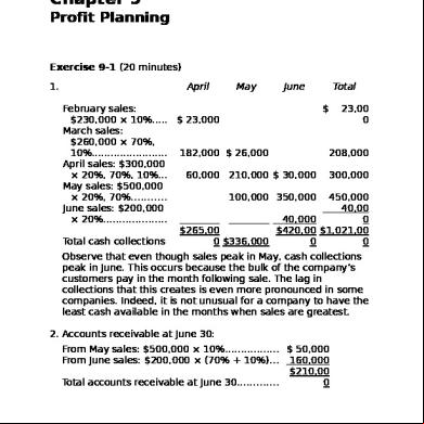
Garrison 13th Edition Chapter 9 486i5v
December 2019 41
Postgresql 9 istration Cookbook - Second Edition 1k204i
November 2019 47
Pearson Science 9 Textbook Second Edition 7240v
December 2019 1,082More Documents from "Ahmad Afandi" 2jz6o
Terjemahan Kitab Matan Safinatun Najah 6w106w
December 2019 211
Summary Of Unquiet Graves Allan Frwin Jones 2u3b6g
October 2021 0
Np100 Edition 9 2009.pdf 6w686o
October 2019 35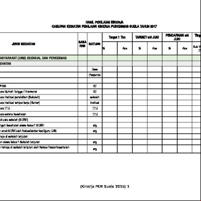
Form Kinerja Puskesmas s322t
February 2021 0
Daftar Pustaka 4h545b
July 2020 0