Howden Axial Fans Hc Centrifugal Fans.pdf 6q5j6q
This document was ed by and they confirmed that they have the permission to share it. If you are author or own the copyright of this book, please report to us by using this report form. Report 2z6p3t
Overview 5o1f4z
& View Howden Axial Fans Hc Centrifugal Fans.pdf as PDF for free.
More details 6z3438
- Words: 54,867
- Pages: 116
HC Centrifugal fans for industry Technical data 2010
Contents
Page 3
Components included in delivery
4
General description
5-7
Direct-driven fans HCBB Ordering key - Fan Ordering key - Accessories Description - Accessories, inlet and outlet Charts - Air flow - Pressure rise Design data Moment of inertia - Sound data Dimensions and weights - Fan Tables, dimensions and weights - Accessories
9 10 11 - 12 13 14 - 15 16 17 - 18 19 - 22 23 - 24
HCBT Ordering key - Fan Ordering key - Accessories Description - Accessories, inlet and outlet Charts - Air flow - Pressure rise Design data Moment of inertia - Sound data Dimensions and weights - Fan Tables, dimensions and weights - Accessories
25 26 27 - 28 29 30 - 31 32 33 - 34 35 - 37 38 - 39
Belt-driven fans with impellers £ 1000 mm Ordering key - Fan Ordering key - Accessories Description - Accessories, inlet and outlet Sound data Dimensions and weights - Fan Tables, dimensions and weights - Accessories Choice of belt drive
40 41 42 - 43 44 45 - 46 47 - 52 53 - 54 55 - 57
Charts - belt-driven fans
58 - 83
Belt-driven fans with impellers > 1000 mm Ordering key - Fan Ordering key - Accessories Description - Accessories, inlet and outlet Sound data Dimensions and weights - Fan Dimensions and weights - Steel base frame Location of fan and motor Slide rails Tables, dimensions and weights - Accessories
84 85 - 86 87 - 88 89 90 - 91 92 - 94 95 - 96 97 98 99 - 100
Motors
101 - 104
Dampers DMEG HXEG
105 106 - 111
Fan theory, vibration and insulation of structure borne sound 112 - 114
The right to alter details and specifications without notice is reserved.
Components included in delivery
Page 4
Direct-driven fans HCBB and HCBT The following components are included as standard: - Stand and housing mounted on steel base frame - Anti-vibration mountings - Inspection cover - Boss equipped draining - Brass ring shaft packing (approx. 0.3 mm clearance) Belt-driven fans with impellers £ 1000 mm The following components are included as standard: - Stand and housing mounted on steel base frame - Anti-vibration mountings - Inspection cover - Boss equipped draining - Brass ring shaft packing (approx. 0.3 mm clearance) - SKF Pop Release bearing - Belts that do not require tensioning after installation Belt-driven fans with impellers > 1000 mm The following components are included as standard: - Inspection cover - Boss equipped draining - Brass ring shaft packing (approx. 0.3 mm clearance) - Bearing housings with spherical roller bearings The fan can be ordered with or without a steel base frame which can always be supplied with anti-vibration mountings if required. Please refer to the ordering key for other possibilities.
The quality assurance system at Fläkt Woods AB, is ISO 9001 certificated. The company also has ISO/DIS 14001 and EMAS environment certification.
General description
Page 5
General Design - Robust design for use in industry. - Direct-driven or belt-driven. - Range of impeller types, (B, P and T impellers). - Right-hand and left-hand versions (clockwise/counter clockwise rotation). For direction of discharge alternatives, please refer to the catalogue section on each fan. Material - Carbon steel as standard. - Stainless or acid-proof steel. - Other materials possible on request. Standards Capacity and sound measurements can be carried out to the following standards: - Capacity
AMCA 210, ISO/DIS 5801
- Sound
AMCA 300, ISO 3744, ISO 9614
The following standards apply for series-produced fans: - Balancing
ISO 1940 Class Q 6.3
- Hot-dip galvanizing
SS 3583 (Class A)
- Flanges
ISO 13351
Surface treatment - Please refer to the individual ordering keys. - All guards (belt guards, shaft guards and cooling disc guards) are epoxy painted in a yellow warning colour, (80 µ). Packing - Fans are delivered on wooden laths suited for handling by fork-lift truck. Instructions - Installation and maintenance instructions are supplied with every fan.
General description
Page 6
HCBB/HCBT Direct-driven centrifugal fans Description - The fans are supplied with B or T type impellers. - A range of 9 sizes. - Each fan size has from 8 to 13 different possibilities as regards impeller diameter. - Impellers are equipped with a hole/groove for an extractor. - Max. operating temperature without heat shielding, 100°C. With heat shielding, 200°C. Refer to accessories. - Max. ambient temperature as regards motor cooling, 40°C. Characteristics - Compact. - Low capital investment cost. - Operational reliability. - Low operating costs. - High efficiency, up to 88% with a type B impeller. Impeller types Type B impellers: - Have backward-curved blades which, depending on size, give an overall efficiency of up to 88%. - Enable the selection of a fan with an at least 80% efficiency within the greater part of the flow-pressure range. - Are primarily for clean gas applications. Type T impellers: - Have straight radial blades for handling dust-laden gases. Not having a wheel inlet ring, this impeller is open and is thus also suitable for fibrous dusts. - Is supplied as standard in a strengthened, wear-resistant design. Dust Dust quantity and impeller choice. - B impeller
0 - 30 mg/m3
- T impeller
3
150 - 1000 mg/m
NB! The stated values apply to dry dust and are for guidance only. Dust composition and air speed greatly affect particle impact and wear. For further information, please ABB Ventilation Products AB, Division Fläkt Industri.
Key charts
10 000
10 000 Total pressure risel, Pa
HCBT
Total pressure rise, Pa
HCBB
5000
2000 1000 500 400 0.05
0.1
0.2
Gas flow m3/s
0.5
1
2
5
10
20
5000
2000 1000 500 400 0.05
0.1
0.2
Gas flow m3/s
0.5
1
2
5
10
General description
Page 7
Belt-driven centrifugal fans Description - High efficiency, belt-driven. - Impellers are equipped with a hole/groove for an extractor. - Max. operating temperature, 350°C. - Supplied with any of the following impellers:
HCGB
HCLP
HCLT
HCMB B impeller
HCMP P impeller
HCMT T impeller *
HCHB
HCHP
HCHT
Characteristics - Compact. * T impellers are available for fans with an impeller diameter of up to 1000 mm.
- Low capital investment cost. - Operational reliability. - Low operating costs. - High efficiency, up to 88% with a type B impeller. Impeller types Type B impellers:
- Have backward-curved blades which, depending on size, give an overall efficiency of up to 88%. - Enable the selection of a fan with an at least 80% efficiency within the greater part of the flow-pressure range. - Are primarily for clean gas applications. Type P impellers: - Have flat, backward-inclined blades. - Are for handling clean gases and gases with a low dust content (e.g. flue gases). Type T impellers: - Have straight radial blades for handling dust-laden gases. Not having a wheel inlet ring, this impeller is open and is thus also suitable for fibrous dusts. - Is supplied as standard in a strengthened, wear-resistant design. Dust Dust quantity and impeller choice. - B impeller
0 - 30 mg/m3
- P impeller
30 - 300 mg/m3
- T impeller
150 - 1000 mg/m3
NB! The stated values apply to dry dust and are for guidance only. Dust composition and air speed greatly affect particle impact and wear. For further information, please ABB Ventilation Products AB, Division Fläkt Industri.
Key charts
10 000
HCLT, HCMT, HCHT Total pressure rise, Pa
Total pressure rise, Pa
HCGB, HCLP, HCM(B,P), HCH(B,P)
10 000
HCH(B,P) HCM(B,P)
5000
HCLP 2000 HCGB 1000 800 0.3 0.5
1
2
Gas flow m3/s
3 45
10
20
5000
HCHT HCMT
2000 HCLT
50
80
1000 800 0.06 0.1
0.2 0.5 Gas flow m3/s
1
2
5
10
Jotter
Page 8
HCBB
Page 9
Ordering Key - HCBB - Direct-driven
Page 10
HCBB-aaa-bb-cc-dd-ee-fff
Size 1) (aaa) 010, 012, 016, 020, 025, 031, 040, 050 and 063. Impeller diameter, cm, 1) (bb) Motor size - IEC (cc) Motor size (cc) is as per the "design data" table on page 16. NB! Motors must always be ordered separately and in accordance with the ordering key on page 16. Designations for rotation and discharge (dd) 11
0o
12
45o
13
90o
14
135o
17
270o
18
315o
61
0o
62
45o
63
90o
64
135o
67
270o
68
315o
Right (RD)
Left (LG)
NB! The above diagrams show the drive side.
Fan version (ee) 01 = standard version. 02 = sparkproof version, (brass ring at the inlet and brass washers at the shaft inlet). Material, finish (fff) 001 = Standard material, GA80-RAL5007 int. and ext.
Not fully welded
Max. temperature 120oC.
002 = Standard material, GP40-01 int. and ext.
Not fully welded
Max. temperature 150oC. 2)
032 = Standard material, GA80TD80-RAL5007 int. and ext.
Not fully welded
Max. temperature 120oC.
072 = Standard material, GA80TD80-RAL5007 int. and ext.
Fully welded
Max. temperature 120oC.
112 = Standard material, GA80TB80-RAL5007 int. and ext.
Fully welded
Max. temperature 120oC.
290 = Standard material, hot-dip galvanized.
Not fully welded
300 = SS 2333 throughout.
Not fully welded
400 = SS 2343 throughout.
Not fully welded
1)
For variants in a size, impeller diameter, number of poles combination, please refer first to page 16, Design data.
2)
GP40-01 primer can be used where temperatures exceed 120°C. This primer tolerates temperatures up to 150°C and vaporises at higher temperatures without emitting any toxic substances.
Ordering key - HCBB - Accessories Heat shield for temperatures up to 200oC
Page 11
HCEZ-07-b-cc
Size: Refer to "Heat shield selection" table, page 23 Variants: Refer to "Heat shield selection" table, page 23 Cleanout cover
HCEZ-09-bb-c-ddd
Cover size: Refer to table on page 23 Location With discharge directions 11 and 61 c = 1 For other discharge directions c=2 Material and finish: Refer to the fff code in the main fan ordering key Inlet taper piece without connecting flange 1)
HCEZ-20-bbb-ccc
Size (= fan size) Material and finish: Refer to the fff code in the main fan ordering key 1)
For direct connection to fans without inlet flange.
Inlet taper piece with connecting flange 2)
HCEZ-21-bbb-ccc
Size (= 040 - 063) Material and finish: Refer to the fff code in the main fan ordering key 2)
For connection to fans with inlet flange or to inlet vane assemblies or regulating dampers.
Counterflange, inlet, (not fitted)
HCEZ-25-bbb-ccc
Size (= fan size) Material 01 = mild steel (unpainted) for welded connection. 03 = SS 2333. 04 = SS 2343. Inlet flange, (fitted)
HCEZ-27-bbb-ccc
Size (= fan size) Material and finish: Refer to the fff code in the main fan ordering key Inlet connecting flange 3)
HCEZ-29-bbb-ccc
Size (= fan size) Material and finish: Refer to the fff code in the main fan ordering key 3)
NB! When connecting to size 031 inlet vane assemblies, size 040 inlet connecting flange must be used.
Fabric duct, inlet, without connecting flanges 4)
HCEZ-aa-bbb
Temp. class 40 = max. 70oC. 41 = max. 200oC. Size (= fan size) 4)
For connection to fans without inlet flange.
Fabric duct, inlet, with connecting flanges 5) Temp. class 45 = max. 70oC. 46 = max. 200oC. Size (= 040 - 063) For material and finish (flanges), refer to the fff code in the main fan ordering key 5)
For connection to fans with inlet flange or to inlet vane assemblies.
NB! When connecting to size 031 inlet vane assemblies, size 040 must be used.
HCEZ-aa-bbb-ccc
Ordering key - HCBB - Accessories, cont. Protective screen, outlet
Page 12
HCEZ-30-bbb-ccc
Size (= fan size) Material and finish: Refer to the fff code in the main fan ordering key Counterflange, outlet, (not fitted)
HCEZ-35-bbb-cc
Size (= fan size) Material 01 = mild steel (unpainted) for welded connection. 03 = SS 2333. 04 = SS 2343. Fabric duct, outlet, with connecting flanges Temp. class 50 = max. 70oC. 51 = max. 200oC. Size (= fan size) Material and finish (flanges), refer to the fff code in the main fan ordering key
HCEZ-aa-bbb-ccc
HCBB - Description - Accessories, inlet and outlet
Page 13
1 12
2
Duct
11 3
4
10
3 3
5, 6
4
5, 6 7 8
3
5, 6 9 2
2 9
5, 6 8
NB! Flanges comply with ISO 13351
Inlet 1 HCEZ-20
Inlet taper piece with protective screen and fixing lugs for connection to inlet without connecting flange. (Pressure loss across the accessory, 0.35 x dyn. press. pd).
2 HCEZ-40, 41
Fabric duct, inlet without connecting flanges. 2)
3 HCEZ-27
Inlet flange, (fitted).
4 HCEZ-21
Inlet taper piece with protective screen and connecting flange for installation to inlet with connecting flange.(Pressure loss across the accessory, 0.35 x dyn. press. pd).
5 HXEG
Inlet vane control assembly, see pages 106 - 111. 1)
6 DMEG
Regulating damper, see page 105. 1)
7 HCEZ-45, 46
Fabric duct, inlet with connecting flange. 2)
8 HCEZ-25
Counterflange, inlet, (not fitted).
9 HCEZ-29
Inlet connecting flange, for fitting ducts without connecting flange.
Outlet 10 HCEZ-30
Protective screen, outlet.
11 HCEZ-50, 51
Fibre duct, outlet, with connecting flanges. 2)
12 HCEZ-35
Counterflange, outlet, (not fitted).
1)
NB! Inlet vane assemblies/regulating dampers must not be connected directly to the fan without checking that the anti-vibration mountings can cope with the increased component load on the fan.
2)
For size and temperature limits, please refer to the appropriate ordering keys.
HCBB - Air flow and dynamic pressure rise charts
Page 14
The charts are valid for gas at a density of 1.2 kg/m2. Gas flow, m3/h 10 000 9000 8000 7000 6000
300
400 500
1000
20 000
2-pole motor
71 71
4-pole motor
025
6-pole motor
63
016
3000
50 47
Size 010
45 42
95
60
31 53
56
90
53 50
50 47 45
500
99
63
33
600
85 80
71 67
35
99
90
75
37
28
95
80
40
26
75 71 67 63
60
50
47
35 33
31 30
8 85 7 82 80
53
50
37
33
56
50 000
063
67
53
42
040
63
56
40
30 000
71
60
45
40 37 35
2000
85 80
42
400 300 0.06
10 000
80 75
4000
1000 900 800 700
3000 4000 5000
Impeller diameter
71
5000
Total pressure rise, Pa
2000
0.1 Gas flow, m3/s
0.2
0.3
0.4
0.5 0.6
0.8
1
2
3
5
6
7 8 9 10
16
6
7 8 9 10
16
1500 1000
Dynamic pressure, Pa
500 400 300 200
Size 010
016
025
040
063
100
50 40 30 0.06
0.1 Gas flow, m3/s
0.2
0.3
0.4
0.5 0.6
0.8
1
Example: Flow 3.0 m3/s, total pressure rise 2100 Pa. Select an HCBB-040 with a 50 cm diameter impeller and a 2-pole motor, or an HCBB-050 with an 80 cm diameter impeller and a 4-pole motor, see chart on next page.
2
3
5
Pressure losses across accessories: HCEZ-20 and 21 inlet taper piece: 0.35 x dynamic pressure Pd.
Dynamic pressure: 330 and 130 Pa respectively. Moment of inertia (J) See page 17.
Sound data See pages 17-18.
HCBB - Air flow and dynamic pressure rise charts
Page 15
The charts are valid for gas at a density of 1.2 kg/m2. Gas flow, m3/h 10 000 9000 8000 7000 6000 5000
300
71 71 71
400 500
1000
2000
10 000
2-pole motor
80
71
4-pole motor 6-pole motor
020
45
3000
42 2000
42
37
75 71
35
31 30
600
80
40
37
33
90
85
42
40
35
95
47 45
45
40
99
50
47
050
67
60
50
50 000
71
63
53
Size 012
30 000
75
67
56
1000 900 800 700
20 000
031
Impeller diameter
4000
Total pressure rise, Pa
3000 4000 5000
67
33 31 30
63 80 75
50 47
25
500
71
45
400 300 0.06
0.1 Gas flow, m3/s
0.2
0.3
0.4
0.5 0.6
0.8
1
2
3
5
6
7 8 9 10
16
5
6
7 8 9 10
16
1500 1000
Dynamic pressure, Pa
500 400 300
Size 012
200
020
031
050
100
50 40 30 0.06
0.1 Gas flow, m3/s
0.2
Moment of inertia (J) See page 17.
0.3
0.4
0.5 0.6
0.8
1
2
3
Sound data See pages 17-18.
HCBB - Design data Fan
Motor *
ImFan peller Motorsize dia. size aaa bb cc
010
012
016
020
Motor size as per R P M IEC
Page 16
Fan
Rated output, kW
Ordering key APAL-
Max. power demand of fan, kW
26 28 30 31
01 01 02 02
63 63 71 71
2820 2820 2840 2840
0.25 0.25 0.37 0.37
2-00025-c-0 2-00025-c-0 2-00037-c-0 2-00037-c-0
0.13 0.17 0.22 0.28
33 35 37 40
02 02 03 03
71 71 80 80
2850 2850 2860 2860
0.55 0.55 0.75 0.75
2-00055-c-0 2-00055-c-0 2-00075-c-0 2-00075-c-0
0.35 0.45 0.54 0.65
30 31 33 35
02 02 03 03
71 71 80 80
2850 2850 2860 2860
0.55 0.55 0.75 0.75
2-00055-c-0 2-00055-c-0 2-00075-c-0 2-00075-c-0
0.28 0.34 0.44 0.57
37 40 42 45
03 03 04 05
80 80 90S 90L
2870 2870 2870 2870
1.1 1.1 1.5 2.2
2-00110-c-0 2-00110-c-0 2-00150-c-0 2-00220-c-0
0.71 0.90 1.2 1.5
33 35 37 40
03 03 03 04
80 80 80 90S
2860 2870 2870 2870
0.75 1.1 1.1 1.5
2-00075-c-0 2-00110-c-0 2-00110-c-0 2-00150-c-0
0.56 0.70 0.89 1.1
42 45 47 50
05 05 06 06
90L 90L 100L 100L
2870 2870 2900 2900
2.2 2.2 3.0 3.0
2-00220-c-0 2-00220-c-0 2-00300-c-0 2-00300-c-0
1.4 1.8 2.2 2.8
25 30 31 33 35
02 02 03 03 03
71 71 80 80 80
2840 2850 2860 2860 2870
0.37 0.55 0.75 0.75 1.1
2-00037-c-0 2-00055-c-0 2-00075-c-0 2-00075-c-0 2-00110-c-0
0.21 0.42 0.52 0.64 0.80
37 40 42 45
04 05 05 06
90S 90L 90L 100L
2870 2870 2870 2900
1.5 2.2 2.2 3.0
2-00150-c-0 2-00220-c-0 2-00220-c-0 2-00300-c-0
1.2 1.5 1.9 2.3
Motor *
ImFan peller Motorsize dia. size aaa bb cc
Rated output, kW
Ordering key APAL-
Max. power demand of fan, kW
40 42
06 07
100L 112M
2900 2850
3.0 4.0
2-00300-c-0 2-00400-c-0
2.6 3.3
45
08 03
132S 80
2855 1420
5.5 0.55
2-00550-c-0 4-00055-c-0
4.2 0.48
47
08 03
132S 80
2855 1420
5.5 0.75
2-00550-c-0 4-00075-c-0
5.2 0.59
50
08 04
132S 90S
2855 1410
7.5 1.1
2-00750-c-0 4-00110-c-0
6.4 0.74
60 63 67 71
10 11 12 14
160M 160L 180M 200L
2920 2920 2930 2955
15 18.5 22 30
2-01500-c-0 2-01850-c-0 2-02200-c-0 2-03000-c-0
50
10 05
160M 90L
2930 1420
11 1.5
2-01100-c-0 4-00150-c-0
53
10 05
160M 90L
2920 1420
15 1.5
2-01500-c-0 4-00150-c-0
10.6 1.2
56
10 06
160M 100L
2920 1430
15 2.2
2-01500-c-0 4-00220-c-0
13 1.6
60
11 06
160L 100L
2920 1430
18.5 2.2
2-01850-c-0 4-00220-c-0
17 2.0
63
12 06
180M 100L
2930 1430
22 3
2-02200-c-0 4-00300-c-0
21 2.5
67
14 07
200L 112M
2955 1435
30 4
2-03000-c-0 4-00400-c-0
27 3.0
71
14 07
200L 112M
2950 1435
37 4
2-03700-c-0 4-00400-c-0
32 3.7
75
16 08
225M 132S
2960 1450
45 5.5
2-04500-c-0 4-00550-c-0
40 4.5
80
17 09
250M 132M
2970 1450
55 7.5
2-05500-c-0 4-00750-c-0
50 5.7
031
040
Motor size as per R P M IEC
12 15 19 25 8.3 0.99
63
07
112M
1435
4
4-00400-c-0
3.1
67
14 08
200L 132S
2950 1450
37 5.5
2-03700-c-0 4-00550-c-0
35 3.9
71
16 08 07
225M 132S 112M
2960 1450 940
45 5.5 2.2
2-04500-c-0 4-00550-c-0 6-00220-c-0
43 4.9 1.4
75
17 09 07
250M 132M 112M
2970 1450 940
55 7.5 2.2
2-05500-c-0 4-00750-c-0 6-00220-c-0
53 6.2 1.7
47 50 53 56
07 07 08 08
112M 112M 132S 132S
2850 2850 2855 2855
4.0 4.0 5.5 7.5
2-00400-c-0 2-00400-c-0 2-00550-c-0 2-00750-c-0
2.8 3.6 4.5 5.7
31 33 35 37 40
03 03 04 04 05
80 80 90S 90S 90L
2870 2870 2870 2870 2870
1.1 1.1 1.5 1.5 2.2
2-00110-c-0 2-00110-c-0 2-00150-c-0 2-00150-c-0 2-00220-c-0
0.70 0.86 1.1 1.3 1.7
42
06 03
100L 80
2700 1420
3.0 0.55
2-00300-c-0 4-00055-c-0
2.7 0.31
80
18 10 08
280S 160M 132S
2977 1460 960
75 11 3
2-07500-c-0 4-01100-c-0 6-00300-c-0
66 7.7 2.1
45
07 03
112M 80
2850 1420
4.0 0.55
2-00400-c-0 4-00055-c-0
3.2 0.37
47
08 03
132S 80
2855 1420
5.5 0.55
2-00550-c-0 4-00055-c-0
3.8 0.44
85 90 95 99
10 11 12 13
160M 160L 180M 180L
1460 1455 1470 1470
11 15 18.5 22
4-01100-c-0 4-01500-c-0 4-01850-c-0 4-02200-c-0
10 12 15 19
50
08 03
132S 80
2855 1420
5.5 0.75
2-00550-c-0 4-00075-c-0
4.8 0.54
53
08 04
132S 90S
2855 1410
7.5 1.1
2-00750-c-0 4-00110-c-0
6.00 0.70
63 67 71 75
16 17 18 18
225M 250M 280S 280S
2960 2970 2977 2977
45 55 75 75
2-04500-c-0 2-05500-c-0 2-07500-c-0 2-07500-c-0
43 50 61 71
56 60 63
10 10 10
160M 160M 160M
2930 2930 2920
80
19 11 09
280M 160L 132M
2975 1455 960
90 15 4
2-09000-c-0 4-01500-c-0 6-00400-c-0
86 11 2.8
025
11 11 15
2-01100-c-0 2-01100-c-0 2-01500-c-0
050
7.5 9.5 12
Voltage code
063
82
20
315S
2982
110
2-11000-c-0
95
85
21 11 09
315M 160L 132M
2982 1455 955
132 15 5.5
2-13200-c-0 4-01500-c-0 6-00550-c-0
108 13 3.4
132
2-13200-c-0
122
1 = 220-240VD/380-420VY 2 = 380-420VD/660-690VY 5 = 500 VY (sizes 63-100) 500 VD (sizes 112-355) * Please refer to pages 101 - 104 for motor details not included here. For further motor data and information on motor versions, please ABB Motors.
87
21
315M
2982
90
12 09
180M 132M
1470 955
18.5 5.5
4-01850-c-0 6-00550-c-0
17 4.2
95
13 10
180L 160M
1470 970
22 7.5
4-02200-c-0 6-00750-c-0
21 5.9
99
14 11
200L 160L
1475 970
30 11
4-03000-c-0 6-01100-c-0
26 7.4
HCBB - Moment of inertia - Sound data
Page 17
Moment of inertia J (=1/4 GD2) Fan size aaa
010
012
016
Imp. dia.
Imp. weight
Fan size
J 2
bb
kg
kg m
26 28 30 31
3.5 3.6 4.2 4.3
0.027 0.028 0.043 0.044
33 35 37 40
5.9 6.0 7.2 7.5
0.086 0.09 0.134 0.14
30 31 33 35
5.8 5.8 5.8 5.9
0.048 0.05 0.09 0.094
37 40 42 45
7.3 7.4 9.0 9.4
0.136 0.142 0.213 0.222
33 35 37 40
8.7 8.8 8.9 8.9
0.093 0.098 0.144 0.152
42 45 47 50
14.3 14.7 14.7 14.8
0.221 0.229 0.342 0.356
aaa
020
025
Imp. dia.
Imp. weight
Fan size
J 2
bb
kg
kg m
25 30 31 33 35
4.4 5.6 5.6 7.3 7.4
0.024 0.048 0.05 0.089 0.093
37 40 42 45
9.0 9.1 10.9 10.9
47 50 53 56
Imp. dia.
Imp. weight
J 2
Fansize
Imp. dia.
Imp. weight
J
aaa
bb
kg
kg m2
050
63 67 71 75 80
29.0 32.0 34.0 42.0 45.0
1.2 1.9 2 2.4 3.1
aaa
bb
kg
kg m
031
40 42 45 47 50
8.9 12.1 14.3 16.5 16.7
0.183 0.287 0.313 0.45 0.458
0.158 0.167 0.248 0.26
60 63 67 71
30.0 31.0 36.0 39.0
0.983 1.03 1.64 1.7
85 90 95 99
62.0 63.0 73.0 78.0
5.4 5.7 8.4 8.9
15.3 15.4 18.0 21.0
0.37 0.395 0.592 0.614
31 33 35 37 40
5.6 7.7 7.8 9.2 9.4
0.073 0.106 0.114 0.167 0.178
50 53 56 60 63
17.0 26.0 27.0 29.0 30.0
0.48 0.72 0.773 1.12 1.2
67 71 75 80
32.0 33.0 37.0 41.0
1.77 1.88 2.78 2.95
42 45 47 50
11.5 11.6 17.3 17.5
0.252 0.266 0.398 0.42
63 67 71 75 80 82 85 87 90 95 99
25.0 25.0 26.0 32.0 45.0 60.0 63.0 64.0 64.0 77.0 78.0
1.9 2.1 2.6 3.6 3.7 5.6 5.7 6.1 6.2 8.9 9.6
53 56 60 63
21.0 24.0 27.0 31.0
0.61 0.645 0.873 1
040
063
Sound data Formulae:
Symbols Lwtot a, b, c Lw a,b,c
= total sound power level for sound paths a, b and c ................. dB (ref. 10-12 W). = sound power level for sound paths a, b and c, respectively by octave band ............................. dB.
Kb, Kc, K2, K3 = corrections for sound paths b and c respectively (for sound path a, the correction = 0) .............. dB. Sound paths:
a = to inlet or outlet duct. b = to surroundings (free-inlet fan). c = to surroundings (fan connected to ducts on both inlet and outlet sides).
NB!The stated values refer to sound power levels. Some fan manufacturers still quote sound pressure levels even though these vary with the acoustic characteristics of the surroundings and distance from the fan. Sound pressure levels, sometimes weighted as dB(A) or dB(C) values, are considerably lower than the corresponding sound power level Lwt. To illustrate this: with a free inlet fan and hemis pherical sound propagation, at a distance of 3 m from the fan, the dB(A) value is 17 - 25 dB lower (depending on fan speed and blade type) than the total sound power level.
Correction K2
Lwtot , see table 2, page 18 a
Lwa, see table 2, page 18
Ltotb
= Lwtot + K2 + K3 a
Lwb = Lwtot + Kb b
Lwtot = Lwtot + K2 + K3 c a
Lwc = Lwtot + Kc c
Table 1. Correction K3, Kb and Kc No. Cor- CorCorrection Kb and Kc, dB of Sound rec- reoles path tion tion Octave band, mid-frequency, Hz K3 63 125 250 500 1000 2000 4000 8000 b -2 Kb -6 -4 -7 -14 -14 -18 -21 -30 6 c -2 Kc -7 -3 -6 -15 -15 -18 -23 -31 b -2 Kb -8 -6 -4 -11 -12 -14 -17 -22 4 c -1 Kc -9 -6 -4 -11 -12 -15 -20 -25 2
b c
-3 -1
Kb Kc
-7 -9
-8 -5
-8 -8
-6 -8
-8 -8
-12 -14
-14 -17
-17 -21
2*
b c
-3 +1
Kb Kc
-3 -3
-9 -8
-10 -6 -9 -10
-12 -15
-16 -21
-21 -27
-23 -29
* Applies only to size 063 and impeller diameter 63, 67, 71 and 75.
K2, dB
5 0
a
-5
b c
-10
-15
0
4000 8000 Dpt, Pa
12 000
HCBB - Sound data cont.
Page 18
Table 2. Sound power levels Lwa and Lwtot (sound path a) a Fan
Im- No.
aaa
010
Octave band, mid-frequency, Hz
dia. pol. bb 63 125 250 500 1000 2000 4000 8000 26 28 30 31 33 35 37 40
Lwtot a dB
84 84 85 86 87 88 89 90
84 84 85 86 87 88 89 90
84 85 86 87 88 89 90 91
79 79 80 81 82 83 84 85
77 78 79 80 81 82 83 84
75 75 76 77 78 79 80 81
72 73 74 75 76 77 78 79
69 69 70 71 72 73 74 75
90 90 91 92 93 94 95 96
2
85 85 87 88 89 90 91 92
85 85 87 88 89 90 91 92
85 86 87 88 89 90 92 93
80 80 82 83 84 85 86 87
78 79 80 81 82 83 85 86
76 76 78 79 80 81 82 83
73 74 75 76 77 78 80 81
70 70 72 73 74 75 76 77
91 91 93 94 95 96 97 98
2
86 87 88 89 90 91 92 93
86 87 88 89 90 91 92 93
86 87 88 89 90 92 93 94
81 82 83 84 85 86 87 88
79 80 81 82 83 85 86 87
77 78 79 80 81 82 83 84
74 75 76 77 78 80 81 82
71 72 73 74 75 76 77 78
92 93 94 95 96 97 98 99
78 83 84 85 86 87 88 89 90 91 93 94 95
78 83 84 85 86 87 88 89 90 91 93 94 95
78 83 84 85 86 87 88 90 90 92 93 94 95
80 78 79 80 81 82 83 84 85 86 88 89 90
77 76 77 78 79 80 81 83 83 85 86 87 88
73 74 75 76 77 78 79 80 81 82 84 85 86
71 71 72 73 74 75 76 78 78 80 81 82 83
69 68 69 70 71 72 73 74 75 76 78 79 80
86 89 90 91 92 93 94 95 96 97 99 100 101
81 84 85 86 88 89 90 90 92 94 95 97 98 80 81 81 83 84
81 84 85 86 88 89 90 90 92 94 95 97 98 80 81 82 83 84
82 85 86 87 88 89 90 91 92 94 95 97 99 76 77 78 79 80
83 79 80 81 83 84 85 85 87 89 90 92 93 70 71 71 73 74
80 78 79 80 81 82 83 84 85 87 88 90 92 68 69 69 71 72
77 75 76 77 79 80 81 81 83 85 86 88 89 66 67 67 69 70
75 73 74 75 76 77 78 79 80 82 83 85 87 62 63 64 65 66
72 69 70 71 73 74 75 75 77 79 80 82 83 57 58 58 60 61
89 90 91 92 94 95 96 96 98 100 101 103 104 84 85 86 87 88
2
012
30 31 33 35 37 40 42 45
016
33 35 37 40 42 45 47 50
020
25 30 31 33 35 37 40 42 45 47 50 53 56
2
31 33 35 37 40 42 45 47 50 53 56 60 63 42 45 47 50 53
2 2 2 2 2 2 2 2 2 2 2 2 2 4 4 4 4 4
025
Fan
Sound power level Lwa, dB
size peller of
Im- No.
Sound power level Lwa, dB
size peller of aaa
Octave band, mid-frequency, Hz dia. pol. bb 63 125 250 500 1000 2000 4000 8000
031
40 42 45 47 50 60 63 67 71 45 47 50
2 2 2 2 2 2 2 2 2 4 4 4
87 87 87 88 88 89 90 90 90 91 91 92 93 93 93 98 98 99 100 100 100 101 101 102 103 103 103 79 79 80 81 81 81 82 82 82
040
50 53 56 60 63 67 71 75 80 50 53 56 60 63 67 71 75 80
2 2 2 2 2 2 2 2 2 4 4 4 4 4 4 4 4 4
93 95 97 98 99 101 102 103 104 81 83 85 86 88 89 90 91 92
93 95 97 98 99 101 102 103 104 81 83 85 86 88 89 90 91 92
94 95 97 99 100 101 102 103 105 82 83 85 87 88 89 90 91 93
050
67 71 75 80 63 67 71 75 80 85 90 95 99 71 75 80
2 2 2 2 4 4 4 4 4 4 4 4 4 6 6 6
102 103 105 106 88 90 91 93 94 96 97 98 99 84 86 87
102 103 105 106 88 90 91 93 94 96 97 98 99 85 87 88
063
63* 67* 71* 75* 80 82 85 87 80 85 90 95 99 80 85 90 95 99
2 2 2 2 2 2 2 2 2 4 4 4 4 6 6 6 6 6
110 111 113 114 107 108 108 109 95 96 98 100 101 88 89 91 93 94
105 106 108 109 107 108 108 109 95 96 98 100 101 88 90 91 94 95
89 90 92 93 95 93 95 96 98 74 76 77
86 87 89 90 92 92 93 95 96 73 74 75
Lwtot a dB
82 84 85 87 88 89 91 92 94 70 72 73
80 82 83 85 86 87 88 90 91 68 69 70
78 79 81 82 84 83 85 86 88 64 66 67
95 96 98 99 101 104 106 107 109 85 87 88
95 97 99 100 101 103 104 105 106 76 78 80 81 83 84 85 86 87
92 89 94 90 96 92 97 94 98 95 100 96 101 97 102 98 103 100 75 72 76 74 78 76 80 77 81 79 82 80 83 81 84 82 86 83
87 88 90 92 93 94 95 96 98 70 71 73 75 76 77 78 79 81
84 86 88 89 90 92 93 94 95 66 68 70 71 73 74 75 76 77
101 103 105 106 107 109 110 111 112 87 89 91 92 94 95 96 97 98
103 104 106 107 88 90 92 93 95 96 97 99 100 81 83 84
104 105 107 108 83 85 86 88 89 91 92 93 94 74 76 77
101 97 102 98 104 100 105 101 81 79 83 81 85 82 86 84 88 85 89 87 90 88 92 89 93 90 72 70 74 72 75 73
95 96 98 99 76 78 80 81 83 84 85 87 88 67 69 70
93 94 96 97 73 75 76 78 79 81 82 83 84 61 63 64
110 111 113 114 94 96 97 99 100 102 103 104 105 89 91 92
104 105 107 108 108 109 109 110 95 97 99 100 102 84 86 87 90 91
108 109 111 112 109 110 110 111 90 91 93 95 96 78 79 81 83 84
100 101 103 104 106 107 107 108 88 90 92 93 95 76 77 79 81 82
91 91 92 92 94 94 95 95 100 98 101 99 101 99 102 100 83 80 85 81 87 83 88 85 90 86 70 65 72 66 73 68 76 70 77 71
114 115 117 118 115 116 116 117 101 102 104 106 107 92 94 95 98 99
96 97 99 100 102 103 103 104 86 87 89 91 92 74 75 77 79 80
* Correction K3, Kb and Kc - see lowest part of Table 1
The above data are valid for the operating ranges shown in the charts on pages 14-15.
HCBB - Dimensions and weights - Fan
Page 19
L E
C
A
F B
Æ D outs.
X
N K
The sketches show a right-hand model.
P
Inspection cover location. CLOutlet
30o
CL Inlet
Y
When delivered, the inspection cover is placed in the upper part of the cao sing, 30 above the horizontal centre line.
Y
G1 G
n holes Æ Z
P3
P2
P1 H2
H3
H3
J1
J2
J2 O1
O2
O2
M1
N3
M2 N1
N2
dd = 11 (0o) = Right-hand model dd = 61 (0o) = Left-hand model
dd = 12 (45o) dd = 62 (45o)
dd = 13 (90o) dd = 63 (90o)
P4
P7 H4
H3 J2
J3 O2 M3 N4
dd = 14 (135o) dd = 64 (135o)
P8 H4
J3 O3 N3
O3 M3 N4
dd = 17 (270o) dd = 67 (270o)
dd = 18 (315o) dd = 68 (315o)
HCBB - Dimensions
Page 20
Dimensions HCBB Fan size
Imp. dia. bb
E
F
H2
H3
H4
M1
M2
M3
N1
N2
N3
N4
P1
P2
P3
P4
P7
P8
010
26-31 33-40
246 297
234 308
360 425
325 380
390 460
319 393
285 357
400 488
549 680
504 632
510 628
637 786
606 722
725 868
644 773
609 736
619 747
610 735
012
30-35 37-45
270 327
257 340
390 465
350 415
425 550
355 437
319 400
442 541
611 759
565 708
566 698
708 874
660 792
792 956
705 852
668 814
682 871
671 858
016
33-40 42-50
297 361
278 371
425 510
380 455
460 555
393 486
357 447
488 599
680 845
632 791
628 775
786 972
722 868 871 1054
773 941
736 901
747 914
735 899
020
25 30-35 37-45 47-56
206 270 327 398
126 220 302 406
310 390 465 560
280 350 415 500
330 425 550 610
261 355 437 541
228 319 400 500
330 442 541 664
445 611 759 943
404 565 708 885
417 520 566 708 698 874 862 1082
507 514 668 682 814 871 999 1012
506 671 858 995
025
31 33-40 42-50 53-63
246 297 361 441
159 233 326 443
360 425 510 615
325 380 455 545
390 460 555 675
324 398 491 608
285 357 447 561
403 554 491 685 602 850 742 1058
504 632 791 992
510 641 606 728 649 609 619 610 628 789 722 871 778 736 747 735 775 975 871 1057 946 901 914 899 961 1210 1056 1287 1153 1105 1125 1106
031
40 42-50 60-71
297 361 489
201 293 480
425 510 675
380 455 600
460 555 740
398 491 677
357 447 629
491 685 632 628 789 722 871 778 736 747 735 602 850 791 775 975 871 1057 946 901 914 899 825 1182 1112 1071 1357 1164 1425 1277 1228 1245 1223
040
50 53-63 67-80
361 441 542
251 368 515
510 615 750
455 545 660
555 675 820
491 608 755
447 561 704
602 850 791 775 975 871 1057 946 901 914 899 742 1058 992 961 1210 1056 1287 1153 1105 1125 1106 917 1319 1245 1194 1512 1292 1577 1415 1363 1385 1361
050
63 67-80 85-99
441 542 670
318 465 650
615 750 920
545 660 805
675 820 1005
628 775 960
561 704 884
756 1078 992 961 1224 1056 1301 1173 1105 1125 1106 931 1339 1245 1194 1519 1292 1591 1435 1363 1385 1361 1153 1669 1563 1489 1892 1590 1958 1765 1688 1714 1684
063
63-80 82-99
552 680
400 585
750 920
660 805
820 1005
775 960
704 884
938 1339 1245 1204 1526 1302 1598 1435 1363 1385 1361 1160 1669 1563 1499 1899 1600 1965 1765 1688 1714 1684
Dimensions L
Motor size
Fan size 010
012
016
020
025
031
040
050
063
338 364 387
384 407
433
444 467
508
558
-
-
-
90S 90L 100L
-
420 445 -
446 471 499
480 505 533
521 546 574
571 624
661 689
-
-
112M 132S 132M
-
-
-
536 602 -
577 643 -
627 693 -
692 758 758
778 844 844
944
160 180
-
-
-
-
769 -
819 896
884 961
970 1047
1070 1147
200L 225M 250M
-
-
-
-
-
989 -
1054 1116 1123
1140 1202 1209
1240 1302 1309
280S 280M 315S 315MA
-
-
-
-
-
-
-
1397 -
1497 1557 1632 1632
63 71 80
516 610 541 660 792 705 792 956 852 958 1164 1041
HCBB - Dimensions and weights
Page 21
Dimensions and weights, HCBB with 2-pole motor Fan size
Imp. dia.
A
B
C
D
O1
O2
O3
J1
J2
J3
N
K
G
G1
P
010
26-28 30-31 33-35 37-40
100 100 100 100
80 80 80 80
105 105 106 106
104 104 104 104
460 460 520 520
430 430 480 480
480 480 550 550
205 205 235 235
190 190 215 215
215 215 250 250
199 214 214 234
262 277 278 298
180 198 176 192
-
142 160 138 154
012
30-31 33-35 37-40 42 45
125 125 125 125 125
100 100 100 100 100
115 115 116 116 116
129 129 129 129 129
480 480 570 570 570
450 450 520 520 520
510 510 610 610 610
215 215 260 260 260
200 200 235 235 235
230 230 280 280 280
224 244 244 275 275
297 317 318 349 349
218 242 218 256 256
-
016
33-37 40 42-45 47-50
160 160 160 160
125 125 125 125
128 128 128 128
164 164 164 164
520 520 610 610
480 480 560 560
550 550 650 650
235 235 280 280
215 215 255 255
250 250 300 300
256 288 288 314
343 375 375 401
252 278 276 310
020
25 30 31-35 37 40-42 45 47-50 53-56
200 200 200 200 200 200 200 200
160 160 160 160 160 160 160 160
145 145 145 146 146 146 146 146
205 205 205 205 205 205 205 205
410 480 480 570 570 570 670 670
380 450 450 520 520 520 610 610
420 510 510 610 610 610 710 710
180 215 215 260 260 260 310 310
165 200 200 235 235 235 280 280
185 230 230 280 280 280 330 330
254 254 274 305 305 332 339 396
357 357 377 409 409 436 443 500
025
31 33 35-37 40 42 45 47-50 53 56-63
250 250 250 250 250 250 250 250 250
200 200 200 200 200 200 200 200 200
165 166 166 166 166 166 166 166 166
255 255 255 255 255 255 255 255 255
460 520 520 520 610 610 610 710 710
430 480 480 480 560 560 560 650 650
480 550 550 550 650 650 650 770 770
205 235 235 235 280 280 280 330 330
190 215 215 215 255 255 255 300 300
215 250 250 250 300 300 300 360 360
294 294 325 325 352 359 416 416 512
031
40 42 45-47 50 60 63 67 71
315 315 315 315 315 315 315 315
250 250 250 250 250 250 250 250
191 191 191 191 192 192 192 192
320 320 320 320 320 320 320 320
520 610 610 610 770 770 770 840
480 560 560 560 720 720 720 790
550 650 650 650 820 820 820 890
235 280 280 280 355 355 355 390
215 255 255 255 330 330 330 365
250 300 300 300 380 380 380 415
040
50 53-56 60 63 67-71 75 80
400 400 400 400 400 400 400
315 315 315 315 315 315 315
223 223 223 223 224 224 224
405 405 405 405 405 405 405
610 710 710 820 930 930 1000
560 650 650 750 840 840 920
650 770 770 870 1000 1000 1060
280 330 330 385 435 435 470
255 300 300 350 390 390 430
050
67 71 75 80
500 500 500 500
400 400 400 400
267 267 267 267
505 505 505 505
930 930 1000 1000
840 840 920 920
1000 1000 1060 1060
435 435 470 470
063
63 67 71 75 80 82 85-87
630 630 630 630 630 630 630
500 500 500 500 500 500 500
317 317 317 317 317 317 317
635 635 635 635 635 635 635
930 1000 1000 1000 1000 1150 1150
840 920 920 920 920 1050 1050
1000 1060 1060 1060 1060 1220 1220
435 470 470 470 470 545 545
Weight, kg incl. motor
X
Y
Z
n
31 34 49 53
34 34 34 34
88 88 88 88
9 9 9 9
2 2 2 2
170 194 170 208 208
41 44 61 68 71
34 34 33 33 33
88 88 88 88 88
9 9 9 9 9
2 2 2 2 2
-
190 216 214 248
57 62 88 97
33 33 34 34
88 88 88 88
9 9 9 9
2 2 2 2
298 290 312 330 330 368 358 412
-
220 212 234 251 251 289 279 333
34 45 48 68 77 86 117 137
34 34 34 33 33 33 34 34
88 88 88 88 88 88 88 88
9 9 9 9 9 9 9 9
2 2 2 2 2 2 2 2
418 418 449 449 476 483 540 540 637
354 348 376 376 414 428 482 460 550
-
265 269 297 297 335 330 387 381 482
45 61 67 67 100 104 125 157 232
34 33 33 33 32 34 33 32 34
88 88 88 88 88 88 88 110 110
9 9 9 9 9 9 9 11 11
2 2 2 2 2 2 2 2 2
377 372 428 428 537 537 575 614
526 509 566 566 687 687 725 765
426 444 488 488 568 568 590 552
-
348 343 399 399 492 492 530 568
81 108 125 129 272 278 307 379
33 34 34 34 34 34 34 34
88 88 88 88 110 110 110 110
9 9 9 9 11 11 11 11
2 2 2 2 2 2 2 2
300 360 360 410 470 470 500
568 569 569 608 646 668 728
750 752 752 792 830 852 910
526 570 570 564 610 658 808
146
524 524 524 562 600 622 680
192 240 245 275 417 427 531
33 34 34 34 34 34 30
110 110 110 110 110 110 110
11 11 11 11 11 11 11
2 2 2 2 2 2 2
390 390 430 430
470 470 500 500
689 915 711 937 770 995 862 1087
664 796 869 873
146 145 145
643 665 722 814
436 491 561 792
34 32 32 34
110 110 110 110
11 11 11 11
2 2 2 2
390 430 430 430 430 495 495
470 500 500 500 500 580 580
761 820 912 912 912 991 991
720 1005 829 829 829 1019 1019
213 185 185 185 185 160
715 772 854 854 854 933 933
494 578 783 789 886 1117 1190
32 32 39 39 39 38 38
110 110 144 144 144 144 144
11 11 14 14 14 14 14
2 2 2 2 2 2 2
1037 1098 1190 1190 1190 1269 1269
HCBB - Dimensions and weights
Page 22
Dimensions and weights, HCBB with 4-pole motor Fan size
Imp. dia.
A
B
C
D
O1
O2
O3
J1
J2
J3
N
K
G
G1
P
Weight, kg incl. motor
X
Y
Z
n
025
42-45 47 50 53
250 250 250 250
200 200 200 200
166 166 166 166
255 255 255 255
610 610 610 710
560 560 560 650
650 650 650 770
280 280 280 330
255 255 255 300
300 300 300 360
294 294 294 325
418 418 418 449
352 352 352 348
-
265 265 265 250
83 87 92 126
34 34 34 34
88 88 88 88
9 9 9 9
2 2 2 2
031
45 47 50
315 315 315
250 250 250
191 191 191
320 320 320
610 610 610
560 560 560
650 650 650
280 280 280
255 255 255
300 300 300
319 319 350
468 468 499
398 398 426
-
300 300 328
81 92 97
33 33 33
88 88 88
9 9 9
2 2 2
040
50 53 56 60-63 67-71 75-80
400 400 400 400 400 400
315 315 315 315 315 315
223 223 223 223 223 223
405 405 405 405 405 405
610 710 710 710 930 930
560 650 650 650 840 840
650 770 770 770 1000 1000
280 330 330 330 435 435
255 300 300 300 390 390
300 360 360 360 470 470
383 383 410 410 417 475
565 565 592 592 600 658
502 480 500 500 510 556
-
354 338 366 366 412 458
94 139 149 156 234 259
33 33 33 33 32 42
88 110 110 110 110 124
9 11 11 11 11 11
2 2 2 2 2 2
050
63 67-71 75 80 85-90 95-99
500 500 500 500 500 500
400 400 400 400 400 400
267 267 267 267 267 267
505 505 505 505 505 505
710 930 930 930 1100 1100
650 840 840 840 1000 1000
770 1000 1000 1000 1180 1180
330 435 435 435 520 520
300 390 390 390 470 470
360 470 470 470 560 560
459 517 517 612 612 650
684 742 742 837 837 875
570 657 657 752 744 766
315 315 298 -
415 472 472 567 567 655
171 265 273 338 431 473
33 32 32 32 33 33
110 110 110 110 110 110
11 11 11 11 11 11
2 2 2 2 2 2
063
80 85 90 95 99
630 630 630 630 630
500 500 500 500 500
317 317 317 317 317
635 635 635 635 635
930 1100 1100 1100 1100
840 1000 1000 1000 1000
1000 1180 1180 1180 1180
435 520 520 520 520
390 470 470 470 470
470 560 560 560 560
662 937 662 937 700 975 700 975 739 1015
722 772 826 826 928
254
607 607 655 655 694
343 452 476 488 552
40 40 33 33 33
144 144 110 110 110
14 14 11 11 11
2 2 2 2 2
Dimensions and weights, HCBB with 6-pole motor Fan size
Imp. dia.
A
B
C
D
O1
O2
O3
J1
J2
J3
N
K
G
G1
P
Weight, kg incl. motor
X
Y
Z
n
050
71 75 80
500 500 500
400 400 400
267 267 267
505 505 505
930 930 930
840 840 840
1000 1000 1000
435 435 435
390 390 390
470 470 470
460 460 517
685 685 742
624 624 657
315
430 430 472
246 254 274
35 35 34
110 110 110
11 11 11
2 2 2
063
80 85-90 95-99
630 630 630
500 500 500
317 317 317
635 635 635
930 1100 1100
840 1000 1000
1000 1180 1180
435 520 520
390 470 470
470 560 560
567 567 662
842 842 937
785 730 772
316 -
537 522 607
286 394 467
30 35 56
110 124 120
11 11 14
2 2 4
HCBB - Heat shield, Cleanout cover
Page 23
Heat shield HCEZ-07-b-cc Shields the motor from radiated heat. Casing side
Table - Heat shield selection cc = cc in the fan code, (IEC motor size) Heat shield Size
No. of motor poles
Variant
Single-speed
Two-speed
cc = 01-09
All
All
b=1
cc = 10-14
2-8
All
b=1
cc = 15
4-8
4/8
b=1
cc = 16
2
2/4
b=1
cc = 16
4-8
4/6, 4/8
b=2
cc = 17
2
-
b=1
cc = 17
4-8
4/6, 4/8
b=2
cc = 18
2
-
b=1
cc = 19
2
-
b=1
cc = 20
2
-
b=1
cc = 21
2
-
b=1
Cleanout cover HCEZ-09-bb-c-ddd Robust, designed for frequent inspections. Double sheet construction and handle.
Impeller
Motor
Shaft packing
Table - Cleanout cover selection Fan size
Impeller dia.
bb
010
26-31 33-40
02 03
012
30-35 37-45
05 06
016
33-40 42-50
07 08
020
25 30-35 37-45 47-56
09 10 11 12
025
31 33-40 42-50 53-63
13 14 15 16
031
40 42-50 60-71
17 18 19
040
50 53-63 67-80
20 21 22
050
63 67-80 85-99
23 24 25
063
63-80 82-99
26 27
HCBB - Dimensions and weights - Accessories NB! Flanges comply to ISO 13351.
HCEZ-30
g
B
HCEZ-35
n holes Æ G
Page 24
HCEZ-50, 51
n holes Æ G
n holes Æ G
g E1
n1 x E
A
C
E1 n2 x F
F1
F1
t + 2,5
t
t
+ 10 130 - 20
D
Fan size
A
A1
010
100
85
012
125
016 020
B
B1
C
D
80
65
170
150
110
100
85
195
160
145
125
110
200
185
160
145
025
250
235
200
031
315
295
040
400
050 063
F
71
E1 33.5
170
71
46
230
195
100
270
230
100
185
330
280
250
230
395
380
315
295
500
480
400
630
600
500
HCEZ-20
E
HCEZ30
HCEZ35
HCEZ50/51
Weight
Weight
Weight
n2 1
kg
kg
kg
8
n1 1
0.6
0.5
1.1
19
12
1
1
0.8
0.7
1.5
5
19
12
1
1
0.9
0.8
1.7
5
19
12
1
1
1.1
1.0
2.1
10
6
19
12
1
1
2.1
1.9
3.9
81.5
10
6
19
14
2
1
2.8
2.4
5.0
51.5
10
6
19
16
2
2
3.5
2.9
6.0
G
t
g
n
---
F1 ---
10
5
19
71
33.5
10
5
49
71
46
10
69
100
49
10
125
81.5
125
56.5
330
125
51.5
125
480
395
125
94
125
380
620
520
125
94.5
125
480
750
620
125
97
125
107 94.5
12
8
32
18
3
2
8.5
7.6
15.5
12
8
32
22
4
3
10.5
9.2
18.8
HCEZ-40/41
HCEZ-21
weight 0.1 - 1.1 kg
HCEZ-25/27
t1
HCEZ-29
HCEZ-45/46 125
h
Æ
Æ D1 ins.
Æ D2 ins.
Æ D4
F
Æ D3
L
ÆE
t
nxÆG
K
ÆD outs.
ÆD
Æ D1 ins.
Æ D2 ins.
+10 40 - 20
45
HCEZ20/21 Weight kg
+10 130 - 20
HCEZ25/27/29 Weight kg
HCEZ45/46 Weight kg
Fan size
D
E
F
G
t
9.5
5
D3 ---
D4 230
n
170
D2 ---
h
139
D1 106
L
105
t1 --
K
010
---
65
32.5
4
0.7
0.5
---
012
130
165
195
9.5
5
--
131
---
---
255
---
65
32.5
4
0.9
0.6
---
016
165
200
240
12
5
--
166
---
---
295
---
70
37.5
4
1.1
0.7
---
020
205
241
280
12
5
--
207
---
---
335
---
70
37.5
8
1.2
1.0
---
025
255
292
330
12
6
--
257
---
---
400
---
75
37.5
8
1.7
1.7
---
031
320
366
405
12
6
--
322
---
---
470
---
80
42.5
8
2.2
2.1
---
040
405
448
490
12
6
2
407
400
528
528
192
192
42.5
12
5.9
3.4
8.4
050
505
551
600
12
8
2
507
500
628
628
192
192
47.5
12
6.8
4.8
11.3
063
635
698
750
14
8
2.5
637
630
809
809
218
218
57.5
16
11.8
5.9
14.5
HCBT
Page 25
Ordering Key - HCBT - Direct-driven
Page 26
HCBT-aaa-bb-cc-dd-ee-fff
Size 1) (aaa) 010, 012, 016, 020, 025, 031, 040, 050 och 063. Impeller diameter, cm, 1) (bb) Motor size - IEC (cc) Motor size (cc) is as per the "design data" table on page 32. NB! Motors must always be ordered separately and in accordance with the ordering key on page 32. Designations for rotation and discharge (dd) 11
0o
12
45o
13
90o
14
135o
17
270o
18
315o
61
0o
62
45o
63
90o
64
135o
67
270o
68
315o
Right (RD)
Left (LG)
NB! The above diagrams show the drive side.
Fan version (ee) 01 = standard version. 02 = sparkproof version, (brass ring at the inlet and brass washers at the shaft inlet). Material, finish (fff) 001 = Standard material, GA80-RAL5007 int. and ext.
Not fully welded
Max. temperature 120oC.
002 = Standard material, GP40-01 int. and ext.
Not fully welded
Max. temperature 150oC. 2)
032 = Standard material, GA80TD80-RAL5007 int. and ext.
Not fully welded
Max. temperature 120oC.
072 = Standard material, GA80TD80-RAL5007 int. and ext.
Fully welded
Max. temperature 120oC.
112 = Standard material, GA80TB80-RAL5007 int. and ext.
Fully welded
Max. temperature 120oC.
290 = Standard material, hot-dip galvanized.
Not fully welded
300 = SS 2333 throughout.
Not fully welded
400 = SS 2343 throughout.
Not fully welded
1)
For variants in a size, impeller diameter, number of poles combination, please refer first to page 32, Design data.
2)
GP40-01 primer can be used where temperatures exceed 120°C. This primer tolerates temperatures up to 150°C and vaporises at higher temperatures without emitting any toxic substances.
Ordering key - HCBT - Accessories Heat shield for temperatures up to 200oC
Page 27
HCEZ-07-b-cc
Size: Refer to "Heat shield selection" table, page 38 Variants: Refer to "Heat shield selection" table, page 38 Cleanout cover
HCEZ-09-bb-c-ddd
Cover size: Refer to table on page 38 Location With discharge directions 11 and 61 c = 1 For other discharge directions c=2 Material and finish: Refer to the fff code in the main fan ordering key Inlet taper piece without connecting flange 1)
HCEZ-20-bbb-ccc
Size (= fan size) Material and finish: Refer to the fff code in the main fan ordering key 1)
For direct connection to fans without inlet flange.
Inlet taper piece with connecting flange 2)
HCEZ-21-bbb-ccc
Size (= 040 - 063) Material and finish: Refer to the fff code in the main fan ordering key 2)
For connection to fans with inlet flange or to inlet vane assemblies or regulating dampers.
Counterflange, inlet, (not fitted)
HCEZ-25-bbb-ccc
Size (= fan size) Material 01 = mild steel (unpainted) for welded connection. 03 = SS 2333. 04 = SS 2343. Inlet flange, (fitted)
HCEZ-27-bbb-ccc
Size (= fan size) Material and finish: Refer to the fff code in the main fan ordering key Inlet connecting flange 3)
HCEZ-29-bbb-ccc
Size (= fan size) Material and finish: Refer to the fff code in the main fan ordering key 3)
NB! When connecting to size 031 inlet vane assemblies, size 040 inlet connecting flange must be used.
Fabric duct, inlet, without connecting flanges 4)
HCEZ-aa-bbb
Temp. class 40 = max. 70oC. 41 = max. 200oC. Size (= fan size) 4)
For connection to fans without inlet flange.
Fabric duct, inlet, with connecting flanges 5) Temp. class 45 = max. 70oC. 46 = max. 200oC. Size (= 040 - 063) For material and finish (flanges), refer to the fff code in the main fan ordering key 5)
For connection to fans with inlet flange or to inlet vane assemblies.
NB! When connecting to size 031 inlet vane assemblies, size 040 must be used.
HCEZ-aa-bbb-ccc
Ordering key - HCBT - Accessories, cont. Flue gas duct, inlet, without connecting flanges 6)
Page 28
HCEZ-aa-bbb-cc
Temp. class 60 = max. 200oC. Size (= fan size) Material (wearing plate) 01 = Steal, primed. 03 = SS 2333. 04 = SS 2343. 6)
For connection to fans without inlet flange.
Flue gas duct, inlet, with connecting flanges 7)
HCEZ-aa-bbb-ccc
Temp. class 65 = max. 200oC. Size (= 040 - 063) For material and finish, (flanges), refer to the fff code in the main fan ordering key NB! Wearing plate is only available in steel, primed or stainless steel qualities depending on choice of ccc code. 7)
For connection to fans with inlet flange or to inlet vane assemblies.
NB! When connecting to size 031 inlet vane assemblies, size 040 must be used.
Protective screen, outlet
HCEZ-30-bbb-ccc
Size (= fan size) Material and finish: Refer to the fff code in the main fan ordering key Counterflange, outlet, (not fitted)
HCEZ-35-bbb-cc
Size (= fan size) Material 01 = mild steel (unpainted) for welded connection. 03 = SS 2333. 04 = SS 2343. Fabric duct, outlet, with connecting flanges
HCEZ-aa-bbb-ccc
Temp. class 50 = max. 70oC. 51 = max. 200oC. Size (= fan size) For material and finish, (flanges), refer to the fff code in the main fan ordering key Flue gas duct, outlet, with connecting flanges 8) Temp. class 70 = max. 200oC. Size (= fan size) For material and finish, (flanges), refer to the fff code in the main fan ordering key NB! Wearing plate is only available in steel, primed or stainless steel qualities depending on choice of ccc code. 8)
For connection to fans with inlet flange or to inlet vane assemblies.
NB! When connecting to size 031 inlet vane assemblies, size 040 must be used.
Regulating damper DMEG (see page 105) Inlet vane control assembly HXEG (see pages 106 - 111).
HCEZ-aa-bbb-ccc
HCBT - Description - Accessories, inlet and outlet
Page 29
1 15
2, 3 Duct
13, 14 4
5
12
4 4
6, 7
5
6, 7 8, 9 10
4
6, 7 11 2, 3
2, 3 11
6, 7 10
NB! Flanges comply with ISO 13351
Inlet 1 HCEZ-20
Inlet taper piece with protective screen and fixing lugs for connection to inlet without connecting flange. (Pressure loss across the accessory, 0.35 x dyn. press. pd).
2 HCEZ-40, 41
Fabric duct, inlet without connecting flange. 2)
3 HCEZ-60
Flue gas duct, inlet without connecting flanges. 2)
4 HCEZ-27
Inlet flange, (fitted).
5 HCEZ-21
Inlet taper piece with protective screen and connecting flange for installation to inlet with connecting flange. (Pressure loss across the accessory, 0.35 x dyn. press. pd).
6 HXEG
Inlet vane control assembly, see pages 106 - 111. 1)
7 DMEG
Regulating damper, see page 105. 1)
8 HCEZ-45, 46
Fabric duct, inlet with connecting flanges. 2)
9 HCEZ-65
Flue gas duct, inlet with connecting flanges. 2)
10 HCEZ-25
Counterflange, inlet, (not fitted).
11 HCEZ-29
Inlet connecting flange, for fitting ducts without connecting flanges.
Outlet 12 HCEZ-30
Protective screen, outlet.
13 HCEZ-50, 51
Fibre duct, outlet, with connecting flanges. 2)
14 HCEZ-70
Flue gas duct, outlet with connecting flanges. 2)
15 HCEZ-35
Counterflange, outlet, (not fitted).
1)
NB! Inlet vane assemblies/regulating dampers must not be connected directly to the fan without checking that the anti-vibration mountings can cope with the increased component load on the fan.
2)
For size and temperature limits, please refer to the appropriate ordering keys.
HCBT - Air flow and dynamic pressure rise charts
Page 30
The charts are valid for gas at a density of 1,2 kg/m2. Gas flow, m3/h 10 000
300
400 500
1000
2000
2-pole motor
71
10 000
20 000
30 000
025
4-pole motor
71
63
6-pole motor
60
5000
56
016
4000
Size 010
47 45
33 31 30 28
80
71
67
35
99
63
33
95
60
31 53
90
56
50 47
26 25
85
75
37
33 31
90
80
40
37 35
95
040
42
40
35
063
50
42
40 37
2000
53
50 47 45
3000
Total pressure rise, Pa
5000
Impeller diameter
71
1000
3000
85
53
80
50
45
42
500 0.06
0.1 Gas flow, m3/s
0.2
0.3
0.4
0.5 0.6
0.8
1
2
3
4
5
6
7
8 9 10
6
7
8 9 10
2000
1000
400
Dynamic pressure, Pa
200
016
Size 010
040
025
063
100
40
20 0.06
0.1 Gas flow, m3/s
0.2
Moment of inertia (J) See page 33.
0.3
0.4
0.5 0.6
0.8
1
2
3
4
5
Sound data See pages 33-34.
HCBT - Air flow and dynamic pressure rise charts
Page 31
The charts are valid for gas at a density of 1,2 kg/m2. Gas flow, m3/h 10 000
300
71 71 71
400 500
1000
2000
5000
10 000
2-pole motor
30 000
031
4-pole motor 6-pole motor
63 60
020 56 53
4000
45 42 40
2000
35 33
85 80
45 42
75
40
71 67
31 30
30 28
63 80 50
25
75 71
47 45
0.1 Gas flow, m3/s
0.2
95 90
33
31
1000
50 47
42 40 37 35
37
050 99
50 47 45
Size 012
3000
500 0.06
20 000
Impeller diameter
5000
Total pressure rise, Pa
3000
0.3
0.4
0.5 0.6
0.8
1
2
3
4
5
6
7
8 9 10
4
5
6
7
8 9 10
2000
1000
400
Size 012
Dynamic pressure, Pa
200
020
031
050
100
40
20 0.06
0.1 Gas flow, m3/s
0.2
0.3
0.4
0.5 0.6
0.8
Example: Flow 3.3 m3/s, total pressure rise 2500 Pa. Select an HCBT-050 with an 80 cm diameter impeller and a 4-pole motor.
1
2
3
Pressure losses across accessories: HCEZ-20 and 21 inlet taper piece: 0.35 x dynamic pressure Pd.
Dynamic pressure: 175 Pa. Moment of inertia (J) See page 33.
Sound data See pages 33-34.
HCBT - Design data Fan
Motor *
Ordering key APAL-
0.25 0.25 0.37 0.37 0.55
2-00025-c-0 2-00025-c-0 2-00037-c-0 2-00037-c-0 2-00055-c-0
0.13 0.17 0.22 0.27 0.31
2850 2860 2870 2870
0.55 0.75 1.1 1.1
2-00055-c-0 2-00075-c-0 2-00110-c-0 2-00110-c-0
0.40 0.51 0.64 0.80
71 71 80 80 80
2840 2850 2860 2870 2870
0.37 0.55 0.75 1.1 1.1
2-00037-c-0 2-00055-c-0 2-00075-c-0 2-00110-c-0 2-00110-c-0
0.34 0.43 0.54 0.68 0.85
04 05 05 06
90S 90L 90L 100L
2870 2870 2870 2900
1.5 2.2 2.2 3
2-00150-c-0 2-00220-c-0 2-00220-c-0 2-00300-c-0
0.95 1.2 1.5 1.9
31 33 35 37 40
03 04 04 05 05
80 90S 90S 90L 90L
2870 2870 2870 2870 2870
1.1 1.5 1.5 2.2 2.2
2-00110-c-0 2-00150-c-0 2-00150-c-0 2-00220-c-0 2-00220-c-0
0.75 0.95 1.2 1.5 1.8
42 45 47 50
06 07 08 08
100L 112M 132S 132S
2900 2850 2855 2855
3 4 5.5 5.5
2-00300-c-0 2-00400-c-0 2-00550-c-0 2-00550-c-0
2.3 2.8 3.5 4.3
25 30 31 33 35
03 04 04 05 05
80 90S 90S 90L 90L
2860 2870 2870 2870 2870
0.75 1.5 1.5 2.2 2.2
2-00075-c-0 2-00150-c-0 2-00150-c-0 2-00220-c-0 2-00220-c-0
0.64 1.1 1.3 1.6 1.9
37 40 42 45
06 07 08 08
100L 112M 132S 132S
2900 2850 2855 2855
3 4 5.5 5.5
2-00300-c-0 2-00400-c-0 2-00550-c-0 2-00550-c-0
2.3 2.8 3.5 4.3
47 50 53 56
08 08 10 10
132S 132S 160M 160M
2855 2855 2930 2920
7.5 7.5 11 15
2-00750-c-0 2-00750-c-0 2-00110-c-0 2-01500-c-0
5.2 6.4 8 9.8
31 33 35 37 40
05 06 07 08 08
90L 100L 112M 132S 132S
2870 2900 2850 2855 2855
2.2 3 4 5.5 7.5
2-00220-c-0 2-00300-c-0 2-00400-c-0 2-00550-c-0 2-00750-c-0
2 2.5 3.4 4.4 5
42
08 04
132S 90S
2855 1410
7.5 1.1
2-00750-c-0 4-00110-c-0
5.5 0.75
45
10 04
160M 2930 90S 1410
11 1.1
2-01100-c-0 4-00110-c-0
6.8 0.9
47
10 05
160M 2930 90L 1420
11 1.5
2-01100-c-0 4-00150-c-0
8.3 1.1
50
10 05
160M 2920 90L 1420
15 1.5
2-01500-c-0 4-00150-c-0
10 1.3
53
11 06
160L 100L
2920 1430
18.5 2.2
2-01850-c-0 4-00220-c-0
13 1.6
56 60 63
11 12 14
160L 2920 180M 2930 200L 2955
18.5 22 30
2-01850-c-0 2-02200-c-0 2-03000-c-0
16 20 24
Fan size aaa
Imp. dia. bb
Motorsize cc
010
25 26 28 30 31
01 01 02 02 02
63 63 71 71 71
2820 2820 2840 2840 2850
33 35 37 40
02 03 03 03
71 80 80 80
28 30 31 33 35
02 02 03 03 03
37 40 42 45
012
016
020
Fan Max. power demand of fan, kW
Motor Rated size outas per R P M put IEC kW
025
Page 32
Fan size aaa
031
040
050
063
Motor *
Ordering key APAL-
Max. power demand of fan kW
7.5 11
2-00750-c-0 2-01100-c-0
5.9 7.5
2930 1420
11 1.5
2-01100-c-0 4-00150-c-0
9.1 1.3
160L 100L
2920 1430
18.5 2.2
2-01850-c-0 4-00220-c-0
14 1.7
11 06
160L 100L
2920 1430
18.5 2.2
2-01850-c-0 4-00220-c-0
16 1.7
60 63
14 14
200L 200L
2950 2950
37 37
2-03700-c-0 2-03700-c-0
50 53 56 60 63
06 07 07 08 09
100L 112M 112M 132S 132M
1430 1435 1435 1450 1450
67 71 75 80
10 10 11 11
160M 160M 160L 160L
1460 1460 1455 1455
63 67
10 11
160M 160L
71
12 09
75
Motor Rated size outas per R P M put, IEC kW
Imp. dia. bb
Motorsize cc
40 42
08 10
132S 160M
2855 2930
45
10 05
160M 90L
47
11 06
50
3 4 4 5.5 7.5
31 34
4-00300-c-0 4-00400-c-0 4-00400-c-0 4-00550-c-0 4-00750-c-0
2.6 2.8 3.5 4.4 5.5
11 11 15 15
4-01100-c-0 4-01100-c-0 4-01500-c-0 4-01500-c-0
6.9 8.3 10 12
1460 1455
11 15
4-01100-c-0 4-01500-c-0
7.2 9.1
180M 132M
1470 960
18.5 4
4-01850-c-0 6-00400-c-0
12 3.5
13 09
180L 132M
1470 955
22 5.5
4-02200-c-0 6-00550-c-0
15 4.4
80
13 10
180L 160M
1470 970
22 7.5
4-02200-c-0 6-00750-c-0
19 5.2
85 90 95 99
14 15 16 17
200L 225S 225M 250M
1475 1480 1480 1480
30 37 45 55
4-03000-c-0 4-03700-c-0 4-04500-c-0 4-05500-c-0
24 27 33 40
80
14 11
200L 160L
1475 970
30 11
4-03000-c-0 6-01100-c-0
27 7.6
85
15 11
225S 160L
1480 970
37 11
4-03700-c-0 6-01100-c-0
33 9.2
90
16 13
225M 180L
1480 970
45 15
4-04500-c-0 6-01500-c-0
38 13
95
17 14
250M 200L
1480 985
55 18.5
4-05500-c-0 6-01850-c-0
48 16
99
14
200L
980
22
6-02200-c-0
19
Voltage code 1 = 220-240VD/380-420VY 2 = 380-420VD/660-690VY 5 = 500 VY (sizes 63-100) 500 VD (sizes 112-355)
* Please refer to pages 101 - 104 for motor details not included here. For further motor data and information on motor versions, please ABB Motors.
HCBT - Moment of inertia - Sound data
Page 33
Moment of inertia J (=1/4 GD2) Fan size
Imp. dia.
Imp. weight
J
Fan size
Imp. dia.
Imp. weight
J
Fan size
Imp. dia.
Imp. weight
J
Fan size
Imp. dia.
Imp. weight
J
aaa
bb
kg
kg m2
aaa
bb
kg
kg m2
aaa
bb
kg
kg m2
aaa
bb
kg
kg m2
25 26 28 30 31
3.3 3.7 3.7 4.1 4.1
0.014 0.02 0.022 0.032 0.033
25 30 31 33 35
3.9 4.8 4.9 6.4 6.5
0.017 0.04 0.045 0.06 0.07
031
40 42 45 47
10.7 13.0 13.3 16.4
0.14 0.22 0.24 0.34 050
0.05 0.052 0.1 0.1
37 40 42 45
7.2 7.3 9.0 9.2
0.11 0.11 0.18 0.19
0.37 0.89 0.92
1.1 1.7 1.8 3.2 3.4
5.4 5.5 6.3 6.5
16.7 21.0 22.0
25.0 32.0 33.0 41.0 46.0
33 35 37 40
50 60 63
63 67 71 75 80
0.022 0.033 0.034 0.052 0.053
47 50 53 56
12.8 13.0 15.5 16.8
0.28 0.29 0.44 0.45
0.35 0.63 0.68 0.99 1
4.5 4.7 6.9 7.2
3.8 4.2 4.3 5.6 5.6
14.6 21.0 22.0 26.0 27.0
50.0 53.0 56.0 66.0
28 30 31 33 35
50 53 56 60 63
85 90 95 99
0.1 0.1 0.16 0.17
31 33 35 37 40
5.0 6.6 6.8 7.9 8.1
0.042 0.067 0.07 0.1 0.11
1.5 1.58 2.8 2.9
3.6 5.1 5.6 8 8.5
6.5 6.5 7.6 8.1
29.0 29.0 36.0 37.0
49.0 52.0 65.0 74.0 75.0
37 40 42 45
67 71 75 80
80 85 90 95 99
31 33 35 37 40
4.5 6.0 6.0 6.9 7.0
0.038 0.056 0.06 0.11 0.11
42 45 47 50 53
12.0 12.0 13.5 13.7 15.2
0.19 0.2 0.3 0.31 0.46
42 45 47 50
9.1 9.3 12.2 12.3
0.18 0.18 0.27 0.28
56 60 63
15.4 21.0 25.0
0.48 0.85 0.88
010
012
016
020
025
040
063
Sound data Symbols
Correction K2 = total sound power level for sound paths a, b and c ................. dB (ref. 10-12 W).
Lw a,b,c
= sound power level for sound paths a, b and c, respectively by octave band ............................. dB.
Kb, Kc, K2, K3 = corrections for sound paths b and c respectively (for sound path a, the correction = 0) .............. dB. Sound paths:
a = to inlet or outlet duct. b = to surroundings (free-inlet fan). c = to surroundings (fan connected to ducts on both inlet and outlet sides).
NB!The stated values refer to sound power levels. Some fan manufacturers still quote sound pressure levels even though these vary with the acoustic characteristics of the surroundings and distance from the fan. Sound pressure levels, sometimes weighted as dB(A) or dB(C) values, are considerably lower than the corresponding sound power level Lwt. To illustrate this: with a free inlet fan and hemis pherical sound propagation, at a distance of 3 m from the fan, the dB(A) value is 17 - 25 dB lower (depending on fan speed and blade type) than the total sound power level.
a
0 K2, dB
Lwtot a, b, c
-5
-10
b
-15
c
-20
0
4000 8000 12 000 Dpt, Pa
Formulae: Lwtot , see table 2, page 34 a
Lwa, see table 2, page 34
Ltotb
= Lwtot + K2 + K3 a
Lwb = Lwtot + Kb b
Lwtot = Lwtot + K2 + K3 c a
Lwc = Lwtot + Kc c
Table 1. Correction K3, Kb and Kc No. Cor- Corof Sound rec- reoles path tion tion K3 63 b 0 Kb -10 6 c -2 Kc -10 b 0 Kb -11 4 c -1 Kc -12 b +1 Kb -6 2 c +1 Kc -7
Correction Kb and Kc, dB Octave band, mid-frequency, Hz 125 250 500 1000 2000 4000 8000 -6 -5
-4 -4
-9 -10
-12 -11
-18 -18
-25 -22
-30 -27
-9 -7
-3 -4
-7 -7
-12 -11
-17 -17
-23 -21
-28 -26
-6 -9
-6 -5
-9 -6
-13 -14
-17 -17
-22 -22
-30 -29
HCBT - Sound data cont.
Page 34
Table 2. Sound power level Lwa and Lwtot (sound path a) a Fan
Im- No.
Fan
Sound power level Lwa, dB
size peller of aaa
Octave band, mid-frequency, Hz dia. pol. bb 63 125 250 500 1000 2000 4000 8000
dB
010
25 26 28 30 31 33 35 37 40
012
28 30 31 33 35 37 40 42 45
2
31 33 35 37 40 42 45 47 50
95 94 95 96 2 96 97 98 99 100
95 96 97 98 99 100 101 102 102
95 94 97 94 98 95 99 96 99 96 100 97 101 98 102 99 103 100
87 88 89 90 90 91 92 93 94
80 82 83 84 84 85 86 87 88
74 75 76 77 77 78 79 80 81
66 69 70 71 71 72 73 74 75
101 102 103 104 104 105 106 107 108
25 30 31 33 35 37 40 42 45 47 50 53 56
88 93 95 96 97 96 2 97 98 99 99 100 101 102
91 93 95 96 97 98 99 100 101 102 103 104 105
91 88 93 92 95 94 96 95 97 96 99 96 100 97 101 98 102 99 102 99 103 100 104 101 105 102
82 86 87 88 89 90 91 92 93 93 94 95 96
76 79 80 81 82 84 85 86 87 87 88 89 90
69 72 74 75 76 77 78 79 80 80 81 82 83
63 64 66 67 68 71 72 73 74 74 75 76 77
96 99 101 102 103 104 105 106 107 107 108 109 110
31 33 35 37 40 42 45 47 50 53 56 60 63 42 45 47 50 53
2 2 2 2 2 2 2 2 2 2 2 2 2 4 4 4 4 4
94 95 96 98 99 100 101 102 104 105 106 107 109 91 92 93 94 95
95 95 96 98 99 101 102 103 104 105 107 108 109 89 90 91 92 93
86 88 89 90 91 92 93 94 95 96 98 99 100 81 81 82 83 84
80 81 82 83 84 86 87 88 89 90 92 93 94 74 74 75 76 77
73 74 75 77 78 79 80 81 82 83 85 86 87 66 67 68 69 70
67 66 67 69 70 73 74 75 76 77 79 80 81 60 61 62 63 64
100 101 102 104 105 106 107 108 109 110 112 113 114 95 96 97 98 99
016
020
025
2
90 89 90 91 92 93 94 95 96
90 92 93 94 95 96 97 98 99
89 89 90 91 92 93 94 95 96
83 83 84 85 86 87 88 89 90
76 77 78 79 80 81 82 83 84
69 70 71 72 73 74 75 76 77
61 64 65 66 67 68 69 70 71
96 97 98 99 100 101 102 103 104
93 93 93 92 94 95 93 95 96 93 96 96 94 97 97 95 98 98 96 99 99 97 99 100 98 100 101
92 92 93 93 94 95 96 97 98
85 86 87 87 88 89 90 91 92
78 80 81 81 82 83 84 85 86
72 73 74 74 75 76 77 78 79
64 67 68 68 69 70 71 72 73
99 100 101 101 102 103 104 105 106
92 95 96 98 99 98 99 100 101 102 104 105 106 88 89 90 91 92
90 92 93 94 94 95 96 97 98
Lwtot a
92 94 95 97 98 98 99 100 101 102 104 105 106 84 85 86 87 88
Im- No.
Sound power level Lwa, dB
size peller of aaa
031
040
050
063
Octave band, mid-frequency, Hz dia. pol. bb 63 125 250 500 1000 2000 4000 8000 40 42 45 47 50 60 63 45 47 50
2 2 2 2 2 2 2 4 4 4
97 100 102 104 105 107 108 88 89 90
99 100 102 104 105 109 111 90 91 92
100 100 102 104 105 110 111 91 92 93
97 91 99 93 101 95 103 96 104 98 107 101 108 102 88 82 89 83 90 84
50 53
4 4
91 91
94 94
92 94
87 91
56 60 63 67 71 75 80
4 4 4 4 4 4 4
93 94 96 98 100 101 102
95 96 97 97 99 99 101 99 103 101 104 102 105 103
93 94 96 94 96 97 98
63 67 71 75 80 85 90 95 99 71 75 80
4 4 4 4 4 4 4 4 4 6 6 6
97 98 100 101 103 105 107 108 109 93 94 96
100 101 102 104 106 108 110 111 112 96 97 99
80 85 90 95 80 85 90 95 99
4 4 4 4 6 6 6 6 6
104 105 107 108 96 98 99 101 103
107 107 109 111 99 101 102 104 106
Lwtot a dB
85 86 88 89 91 95 96 76 77 78
78 79 81 83 84 88 89 69 70 71
72 71 73 75 76 82 83 63 64 65
105 106 108 110 111 115 116 96 97 98
83 85
76 79
69 72
63 66
98 99
87 88 90 91 92 94 95
81 82 84 84 85 87 88
74 75 77 76 78 79 80
68 69 71 70 72 73 74
101 102 104 105 107 108 109
98 101 103 104 106 106 108 109 110 94 95 97
93 89 98 92 100 94 101 95 103 97 101 98 103 99 104 100 105 102 89 85 90 86 92 88
82 86 88 89 91 91 92 93 95 78 79 81
75 79 81 82 84 83 85 86 87 71 72 74
69 73 75 76 78 77 79 80 81 65 66 68
104 106 108 109 111 112 114 115 116 100 101 103
105 108 110 111 97 99 100 102 104
100 97 105 99 107 101 108 102 92 89 94 90 95 92 97 94 99 95
90 93 95 96 82 83 85 87 88
82 86 88 89 74 76 77 79 81
76 80 82 83 68 70 71 73 75
111 113 115 116 103 105 106 108 110
The above data are valid for the operating ranges shown in the charts on pages 30-31.
HCBT - Dimensions and weights - Fan
Page 35
L E
C
A
F B
Æ D outs.
X
N K
The sketches show a right-hand model
P
Inspection cover location. 30
CLOutlet
o
CL Inlet
Y
When delivered, the inspection cover is placed in the upper part of the cao sing, 30 above the horizontal centre line.
Y
G1 G
n holes Æ Z
P2
P1 H2
P3
H3
J1
H3
J2 O1
J2 O2
M1
O2
M2 N1
N3 N2
dd = 11 (0o) = Right-hand model dd = 61 (0o) = Left-hand model
dd = 12 (45o) dd = 62 (45o)
dd = 13 (90o) dd = 63 (90o)
P4
P7
J2
J3 O2 M3 N4
dd = 14 (135o) dd = 64 (135o)
P8
H4
H3
H4
J3 O3 N3
O3 M3 N4
dd = 17 (270o) dd = 67 (270o)
dd = 18 (315o) dd = 68 (315o)
HCBT - Dimensions
Page 36
Dimensions HCBT Fan size
Imp. dia. bb
E
F
H2
H3
H4
M1
M2
M3
N1
N2
N3
N4
P1
P2
P3
P4
P7
P8
010
25 26-31 33-40
206 246 297
176 234 308
310 360 425
280 325 380
330 390 460
261 319 393
228 285 357
330 400 488
445 549 680
404 504 632
417 510 628
520 637 786
516 606 722
610 725 868
541 644 773
507 609 736
514 619 747
506 610 735
012
28 30-35 37-45
225 270 327
191 257 340
330 390 465
300 350 415
355 425 550
289 355 437
255 319 400
363 442 541
494 611 759
452 565 708
461 566 698
576 708 874
555 660 792
663 792 956
589 705 852
554 668 814
560 682 871
552 671 858
016
31 33-40 42-50
246 297 361
204 278 371
360 425 510
325 380 455
390 460 555
319 393 486
285 357 447
400 488 599
549 680 845
504 632 791
510 628 775
637 786 972
606 725 722 868 871 1054
644 773 941
609 736 901
619 747 914
610 735 899
020
25 30-35 37-45 47-56
206 270 327 398
126 220 302 406
310 390 465 560
280 350 415 500
330 425 550 610
261 355 437 541
228 319 400 500
330 442 541 664
445 611 759 943
404 565 708 885
417 520 566 708 698 874 862 1082
507 514 668 682 814 871 999 1012
506 671 858 995
025
31 33-40 42-50 53-63
246 297 361 441
159 233 326 443
360 425 510 615
325 380 455 545
390 460 555 675
324 398 491 608
285 357 447 561
403 554 491 685 602 850 742 1058
504 632 791 992
510 641 606 728 649 609 619 610 628 789 722 871 778 736 747 735 775 975 871 1057 946 901 914 899 961 1210 1056 1287 1153 1105 1125 1106
031
40 42-50 60-63
297 361 489
201 293 480
425 510 675
380 455 600
460 555 740
398 491 677
357 447 629
491 685 632 628 789 722 871 778 736 747 735 602 850 791 775 975 871 1057 946 901 914 899 825 1182 1112 1071 1357 1164 1425 1277 1228 1245 1223
040
50 53-63 67-80
361 441 542
251 368 515
510 615 750
455 545 660
555 675 820
491 608 755
447 561 704
602 850 791 775 975 871 1057 946 901 914 899 742 1058 992 961 1210 1056 1287 1153 1105 1125 1106 917 1319 1245 1194 1512 1292 1577 1415 1363 1385 1361
050
63 67-80 85-99
441 542 670
318 465 650
615 750 920
545 660 805
675 820 1005
628 775 960
561 704 884
756 1078 992 961 1224 1056 1301 1173 1105 1125 1106 931 1339 1245 1194 1519 1292 1591 1435 1363 1385 1361 1153 1669 1563 1489 1892 1590 1958 1765 1688 1714 1684
063
80 85-99
552 680
400 585
750 920
660 805
820 1005
775 960
704 884
938 1339 1245 1204 1526 1302 1598 1435 1363 1385 1361 1160 1669 1563 1499 1899 1600 1965 1765 1688 1714 1684
Dimensions L
Motorsize
Fan size 010
012
016
020
025
031
040
050
063
338 364 387
384 407
433
467
-
-
-
-
-
90S 90L 100L
-
420 445 473
446 471 499
480 505 533
521 546 574
596 624
689
-
-
112M 132S 132M
-
-
502 568 -
536 602 -
577 643 -
693 -
692 758 758
844
-
160 180
-
-
-
727 -
769 846
819 -
884 -
970 1047
1070 1147
200L 225M 250M
-
-
-
-
939 -
989 -
-
1140 1202 1209
1240 1302 1309
63 71 80
516 610 541 660 792 705 792 956 852 958 1164 1041
HCBT - Dimensions and weights
Page 37
Dimensions and weights, HCBT with 2-pole motorer Fan size
Imp. dia.
A
B
C
D
010
25 26 28-31 33 35-40
100 100 100 100 100
80 80 80 80 80
105 105 105 106 106
012
28 30 31-35 37-42 45
125 125 125 125 125
100 100 100 100 100
016
31 33-35 37-40 42 45 47-50
160 160 160 160 160 160
020
25 30-31 33-35 37 40 42-45 47-50 53-56
O1
O2
O3
J1
J2
J3
N
K
G
G1
P
104 104 104 104 104
410 460 460 520 520
380 430 430 480 480
420 480 480 550 550
180 205 205 235 235
165 190 190 215 215
185 215 215 250 250
199 199 214 214 234
262 262 277 278 298
174 176 210 174 190
-
136 138 172 136 152
115 115 115 116 116
129 129 129 129 129
430 480 480 570 570
410 450 450 520 520
450 510 510 610 610
190 215 215 260 260
180 200 200 235 235
200 230 230 280 280
224 224 244 275 302
297 297 317 349 376
220 214 238 245 288
-
125 125 125 125 125 125
128 128 128 128 128 128
164 164 164 164 164 164
460 520 520 610 610 610
430 480 480 560 560 560
480 550 550 650 650 650
205 235 235 280 280 280
190 215 215 255 255 255
215 250 250 300 300 300
256 288 288 314 322 378
343 375 375 401 409 465
268 278 278 310 314 376
200 200 200 200 200 200 200 200
160 160 160 160 160 160 160 160
145 145 145 146 146 146 146 146
205 205 205 205 205 205 205 205
410 480 480 570 570 570 670 670
380 450 450 520 520 520 610 610
420 510 510 610 610 610 710 710
180 215 215 260 260 260 310 310
165 200 200 235 235 235 280 280
185 230 230 280 280 280 330 330
274 304 304 332 339 396 396 491
377 407 407 436 443 506 500 595
025
31 33 35 37-40 42 45-50 53-56 60 63
250 250 250 250 250 250 250 250 250
200 200 200 200 200 200 200 200 200
165 166 166 166 166 166 166 166 166
255 255 255 255 255 255 255 255 255
460 520 520 520 610 610 710 820 820
430 480 480 480 560 560 650 750 750
480 550 550 550 650 650 770 870 870
205 235 235 235 280 280 330 385 385
190 215 215 215 255 255 300 350 350
215 250 250 250 300 300 360 410 410
325 352 359 416 416 512 512 551 589
031
40 42-45 47-50 60-63
315 315 315 315
250 250 250 250
191 191 191 192
320 320 320 320
520 610 610 840
480 560 560 790
550 650 650 890
235 280 280 390
215 255 255 365
250 300 300 415
428 536 536 614
Weight, kg incl. motor
X
Y
Z
n
28 34 37 51 56
34 34 34 33 33
88 88 88 88 88
9 9 9 9 9
2 2 2 2 2
172 166 190 197 240
34 43 46 71 85
33 34 34 33 33
88 88 88 88 88
9 9 9 9 9
2 2 2 2 2
-
208 216 216 249 253 315
45 65 70 99 103 120
33 33 33 34 34 33
88 88 88 88 88 88
9 9 9 9 9 9
2 2 2 2 2 2
316 335 335 368 372 438 394 494
-
237 256 256 289 293 359 315 447
41 58 61 90 95 112 136 201
34 34 34 33 33 33 34 33
88 88 88 88 88 88 88 110
9 9 9 9 9 9 9 11
2 2 2 2 2 2 2 2
449 476 483 540 540 636 636 675 714
394 420 428 472 482 530 518 534 658
146
296 321 330 387 387 467 467 505 543
60 85 89 105 126 171 231 279 336
34 33 33 33 32 34 32 34 33
88 88 88 88 88 110 110 110 110
9 9 9 9 9 11 11 11 11
2 2 2 2 2 2 2 2 2
565 685 685 764
480 536 536 552
-
399 492 492 568
110 179 199 385
34 34 33 33
88 110 110 110
9 11 11 11
2 2 2 2
K
G
G1
P
Weight, kg incl. motor
X
Y
Z
n
Dimensions and weights, HCBT with 4-pole motorer Fan size
Imp. dia.
A
B
C
D
025
42-45 47-50 53
250 250 250
200 200 200
166 166 166
031
45 47-50
315 315
250 250
040
50 53-56 60 63 67-71 75-80
400 400 400 400 400 400
050
63 67 71 75-80 85 90 95 99
063
80 85 90 95
O1
O2
O3
J1
J2
J3
N
255 255 255
610 610 710
560 560 650
650 650 770
280 280 330
255 255 300
300 300 360
325 325 352
449 449 476
356 356 356
-
257 257 257
100 103 147
35 34 34
110 110 110
11 11 11
2 2 2
191 191
320 320
610 610
560 560
650 650
280 280
255 255
300 300
350 377
499 526
426 452
-
328 328
101 120
33 33
110 110
11 11
2 2
315 315 315 315 315 315
223 223 223 223 224 224
405 405 405 405 405 405
610 710 710 710 930 930
560 650 650 650 840 840
650 770 770 770 1000 1000
280 330 330 330 435 435
255 300 300 300 390 390
300 360 360 360 470 470
410 416 474 474 569 569
592 599 657 658 753 753
524 492 556 556 696 696
-
368 336 400 400 539 539
127 173 191 200 313 343
33 33 34 33 40 40
110 110 110 110 124 124
11 11 11 11 15 15
2 2 2 2 2 2
500 500 500 500 500 500 500 500
400 400 400 400 400 400 400 400
267 267 267 267 267 267 267 267
505 505 505 505 505 505 505 505
710 930 930 930 1100 1100 1100 1150
650 840 840 840 1000 1000 1000 1050
770 1000 1000 1000 1180 1180 1180 1220
330 435 435 435 520 520 520 545
300 390 390 390 470 470 470 495
360 470 470 470 560 560 560 580
612 612 651 651 689 711 711 770
837 837 876 876 914 936 936 995
752 752 774 750 798 774 774 822
298 -
582 567 620 620 658 680 680 737
256 352 388 418 570 622 631 713
40 38 37 36 40 40 40 39
124 124 124 124 124 124 124 124
15 15 15 15 15 15 15 15
2 2 2 2 2 2 2 2
630 630 630 630
500 500 500 500
317 317 317 317
635 635 635 635
930 1100 1100 1150
840 1000 1000 1050
1000 1180 1180 1220
435 520 520 545
390 470 470 495
470 560 560 580
739 761 761 820
1014 1036 1036 1095
958 980 980 1037
275 275 275 289
708 730 730 787
396 651 692 743
37 37 37 33
124 124 124 144
15 15 15 14
2 2 2 2
K
G
G1
P
Weight, kg incl. motor
X
Y
Z
n
Dimensions and weights, HCBT with 6-pole motorer Fan size 050
063
Imp. dia.
A
B
C
D
O1
O2
71 75 80
500 500 500
400 400 400
267 267 267
80 85 90 95-99
630 630 630 630
500 500 500 500
317 317 317 317
O3
J1
J2
J3
N
505 505 505
930 930 930
840 840 840
1000 1000 1000
435 435 435
390 390 390
470 470 470
517 517 612
742 742 837
657 657 752
315 315 298
472 472 567
301 313 345
35 35 34
110 110 110
11 11 11
2 2 2
635 635 635 635
930 1100 1100 1100
840 1000 1000 1000
1000 1180 1180 1180
435 520 520 520
390 470 470 470
470 560 560 560
662 662 700 739
937 937 975 1014
824 772 826 928
254
632 607 655 694
396 499 548 608
35 37 37 35
110 120 120 110
11 15 15 11
2 4 4 2
HCBT - Heat shield, Cleanout cover
Page 38
Heat shield HCEZ-07-b-cc Shields the motor from radiated heat. Casing side
Table - Heat shield selection cc = cc in the fan code, (IEC motor size) Size
No. of motor poles
Heat shield
Variant
Single-speed
Two-speed
cc = 01-09
Alla
Alla
b=1
cc = 10-14
2-8
Alla
b=1
cc = 15
4-8
4/8
b=1
cc = 16
2
2/4
b=1
cc = 16
4-8
4/6, 4/8
b=2
cc = 17
2
-
b=1
cc = 17
4-8
4/6, 4/8
b=2
cc = 18
2
-
b=1
cc = 19
2
-
b=1
cc = 20
2
-
b=1
cc = 21
2
-
b=1
Cleanout cover HCEZ-09-bb-c-ddd Robust, designed for frequent inspections. Double sheet construction and handle.
Impeller
Motor
Shaft packing
Table - Cleanout cover selection Fan size
Impeller dia.
bb
010
25 26-31 33-40
01 02 03
012
28 30-35 37-45
04 05 06
016
33-40 42-50
07 08
020
25 30-35 37-45 47-56
09 10 11 12
025
31 33-40 42-50 53-63
13 14 15 16
031
40 42-50 60-71
17 18 19
040
50 53-63 67-80
20 21 22
050
63 67-80 85-99
23 24 25
063
63-80 82-99
26 27
HCBT - Dimensions and weights - Accessories NB! Flanges comply to ISO 13351.
HCEZ-30
g
B
HCEZ-35
HCEZ-50, 51
HCEZ-70 n holes Æ G
n holes Æ G
n holes Æ G
n holes Æ G
Page 39
g E1
n1 x E
A
C
A1 x B1 Sheet steel insert
E1 n2 x F
F1
F1
A
A1
B
B1
C
D
E
010
100
85
80
65
170
150
012
125
110
100
85
195
016
160
145
125
110
020
200
185
160
145
025
250
235
200
031
315
295
040
400
050 063
71
E1 33.5
170
71
46
230
195
100
270
230
100
185
330
280
250
230
395
380
315
295
500
480
400
630
600
500
HCEZ-20
+ 10 130 - 20
+ 10 130 - 20
D
Fan Size
t
t
t
t + 2,5
F
HCEZ30
HCEZ35
HCEZ50/51
HCEZ70
Weight
Weight
Weight
Weight
kg
kg
kg
kg
0.6
0.5
1.1
1.5
G
t
g
---
F1 ---
10
5
19
71
33.5
10
5
19
12
1
1
0.8
0.7
1.5
2.3
49
71
46
10
5
19
12
1
1
0.9
0.8
1.7
2.3
69
100
49
10
5
19
12
1
1
1.1
1.0
2.1
3.1
125
81.5
125
56.5
10
6
19
12
1
1
2.1
1.9
3.9
5.3
330
125
51.5
125
81.5
10
6
19
14
2
1
2.8
2.4
5.0
6.6
480
395
125
94
125
51.5
10
6
19
16
2
2
3.5
2.9
6.0
8.0
380
620
520
125
94.5
125
12
8
32
18
3
2
8.5
7.6
15.5
18.3
480
750
620
125
97
125
12
8
32
22
4
3
10.5
9.2
18.8
22.6
107 94.5
HCEZ-25/27
HCEZ-21
n
n1 n2 8 1 1
HCEZ-40/41
HCEZ-60
Weight 0.1 - 1.1 kg
with sheet steel insert
HCEZ-45/46
HCEZ-29
t1
Æ
Æ D5
Æ D3 ins.
L
F
ÆE
Æ D4
t
nxÆG
K
ÆD outs.
ÆD
Æ D1 ins.
Æ D3 ins.
+10 40 - 20
45
with sheet steel insert
60
h
Æ D1 ins.
HCEZ-65
145
125
HCEZ20/21 Weight kg
+10 130 - 20
+10 40 - 20
+10 130 - 20
Æ D3 ins.
Æ D1 Æ D2 ins.
Æ D2
HCEZ25/27/29 Weight kg
HCEZ45/46 Weight kg
HCEZ60 Weight kg
HCEZ65 Weight kg
Fan Size
D
E
F
G
t
9.5
5
D3 ---
D4 ---
D5 230
n
170
D2 85
h
139
D1 106
L
105
t1 --
K
010
---
65
32.5
4
0.7
0.5
---
0.6
---
012
130
165
195
9.5
5
--
131
110
---
---
255
---
65
32.5
4
0.9
0.6
---
0.8
---
016
165
200
240
12
5
--
166
145
---
---
295
---
70
37.5
4
1.1
0.7
---
1.0
---
020
205
241
280
12
5
--
207
185
---
---
335
---
70
37.5
8
1.2
1.0
---
1.1
---
025
255
292
330
12
6
--
257
235
---
---
400
---
75
37.5
8
1.7
1.7
---
1.4
---
031
320
366
405
12
6
--
322
290
---
---
470
---
80
42.5
8
2.2
2.1
---
1.7
---
040
405
448
490
12
6
2
407
375
400
528
528
192
192
42.5
12
5.9
3.4
8.4
2.2
8.8
050
505
551
600
12
8
2
507
475
500
628
628
192
192
47.5
12
6.8
4.8
11.3
2.8
12.2
063
635
698
750
14
8
2.5
637
595
630
809
809
218
218
57.5
16
11.8
5.9
14.5
3.5
15.2
Belt-driven fans with impeller diameter ≤ 1000 mm
Page 40
Ordering Key - Belt-driven fans with impeller diameter £ 1000 mm
Page 41
HCGB HCL x HCMx HCH x -aaa-bb-cc-dd-ee-fff Impeller B = Backward-curved blades (Type B impellers are not available for the HCL fan). P = Flat, backward-inclined blades. T = Straight, radial blades. Size (aaa), see page 58 and fan charts Components included in delivery (bb) 02 = Fan without motor, anti-vibration mountings and belt drive. 03 = Fan with motor, anti-vibration mountings and belt drive, (all fitted). NB! Motor and belt drive should be specified separately. IEC motor size (cc) 03 04 05 06 07 08 09
= = = = = = =
80 90S 90L 100L 112M 132S 132M
10 11 12 13 14 15 16
= = = = = = =
160M 160L 180M 180L 200L 225S 225M
17 18 19 20 21
= = = = =
250M 280S 280M 315S 315M
For the various fans, motor size can be found from the tables on pages 48 - 49.
Designations for rotation and discharge (dd) 0o
11 Right (RD)
W
61 Left (LG)
45o
12
Z
W 0o
45o
62
13
90o
14
Z
63
Z
135o
270o
17
Z 90o
64
W
18
W 135o
270o
67
W
Z
315o
W
68
315o
Z
NB! The above diagrams show the drive side
Fan version (ee) 01 = standard version. 02 = sparkproof version, (brass ring at the inlet and brass washers at the shaft inlet). Material, finish 1) (fff) 001 = Standard material, GA80-RAL5007 int. and ext.
Not fully welded
Max. temperature 120oC.
002 = Standard material, GP40-01 int. and ext.
Not fully welded
Max. temperature 150oC. 2)
032 = Standard material, GA80TD80-RAL5007 int. and ext.
Not fully welded
Max. temperature 120oC.
072 = Standard material, GA80TD80-RAL5007 int. and ext.
Fully welded
Max. temperature 120oC.
112 = Standard material, GA80TB80-RAL5007 int. and ext.
Fully welded
Max. temperature 120oC.
290 = Standard material, hot-dip galvanized.
Not fully welded
300 = Except for shaft, guard and motor actuator, parts in gas , (stand included), in SS 2333.
Not fully welded
400 = Except for shaft, guard and motor actuator, parts in gas in acid-proof SS 2343, stand in SS 2333.
Not fully welded
1)
Removable guards around rotating parts are epoxy painted in a yellow, warning colour, (80 µ).
2)
GP40-01 primer can be used where temperatures exceed 120°C. This primer tolerates temperatures up to 150°C and vaporises at higher temperatures without emitting any toxic substances.
Ordering key - Accessories Belt drive
Page 42
HCEZ-01-bbb-c-dd
Size: Refer to the "Belt drive selection" tables on pages 55 - 57 Form of delivery: 1 = fitted to the fan. 2 = not fitted Fan size: Refer to the tables on pages 55 - 57 NB! The "Belt drive selection" tables cover rated motor powers up to 30 kW. Belt drives with higher rated motors must be selected from the data selection program - see HC data selection program or Fläkt Woods AB.
Cooling disc
HCEZ-06-bb
Size: Refer to the "Cooling disc selection" table on page 53 Cleanout cover
HCEZ-09-bb-c-ddd
Cover size: Refer to table on page 53 Location With discharge directions 11 and 61 For other discharge directions
c=1 c=2
Material and finish: Refer to the fff code in the main fan ordering key Speed monitor
HCEZ-13-bb
Size: Refer to the "Speed monitor selection" table on page 53 Inlet taper piece without connecting flange 1)
HCEZ-20-bbb-ccc
Size (= fan size) Material and finish: Refer to the fff code in the main fan ordering key 1)
For direct connection to fans without inlet flange.
Inlet taper piece with connecting flange 2)
HCEZ-21-bbb-ccc
Size (= 040 - 100) Material and finish: Refer to the fff code in the main fan ordering key 2)
For connection to fans with inlet flange or to inlet vane assemblies or regulating dampers.
NB! When connecting to size 031 inlet vane assemblies, size 040 inlet connecting flange must be used.
Counterflange, inlet, (not fitted)
HCEZ-25-bbb-cc
Size (= fan size) Material 01 = mild steel (unpainted) for welded connection. 03 = SS 2333. 04 = SS 2343. Inlet flange, (fitted)
HCEZ-27-bbb-ccc
Size (= fan size) Material and finish: Refer to the fff code in the main fan ordering key Inlet connecting flange
HCEZ-29-bbb-ccc
Size (= fan size) Material and finish: Refer to the fff code in the main fan ordering key Fabric duct, inlet, without connecting flanges 3) Temp. class 40 = max 70°C. 41 = max 200°C. 42 = max 350°C
Size (= fan size) 3)
For connection to fans without inlet flange.
HCEZ-aa-bbb
Ordering key - Accessories, cont. Fabric duct, inlet, with connecting flanges 4)
Page 43
HCEZ-aa-bbb-ccc
Temp. class 45 = max 70°C. 46 = max 200°C. 47 = max 350°C. Size (= 040 - 100) For material and finish (flanges), refer to the fff code in the main fan ordering key 4)
For connection to fans with inlet flange.
Flue gas duct, inlet, without connecting flanges 5)
HCEZ-aa-bbb-cc
Temp. class 60 = max 200°C. 61 = max 350°C. Size (= fan size) Material (wearing plate) 01 = Steal, primed. 03 = SS 2333. 04 = SS 2343. 5)
For connection to fans without inlet flange
Flue gas duct, inlet, with connecting flanges 6)
HCEZ-aa-bbb-ccc
Temp. class 65 = max 200°C. 66 = max 350°C. Size (= 040 - 100) For material and finish, (flanges), refer to the fff code in the main fan ordering key 6)
For connection to fans with inlet flange.
NB! Wearing plate is only available in steel, primed or stainless steel qualities depending on choice of ccc code.
Protective screen, outlet
HCEZ-30-bbb-ccc
Size (= fan size) Material and finish: Refer to the fff code in the main fan ordering key Counterflange, outlet, (not fitted)
HCEZ-35-bbb-cc
Size (= fan size) Material 01 = mild steel (unpainted) for welded connection. 03 = SS 2333. 04 = SS 2343. Fabric duct, outlet, with connecting flanges
HCEZ-aa-bbb-ccc
Temp. class 50 = max 70°C. 51 = max 200°C. 52 = max 350°C.. Size (= fan size) For material and finish, (flanges), refer to the fff code in the main fan ordering key Flue gas duct, outlet, with connecting flanges 7) Temp. class 70 = max 200°C. 71 = max 350°C.. Size (= fan size) For material and finish, (flanges), refer to the fff code in the main fan ordering key 7)
NB! Wearing plate is only available in steel, primed or stainless steel qualities depending on choice of ccc code.
Regulating damper DMEG (see page 105) Inlet vane control assembly HXEG (see pages 106 - 111)
HCEZ-aa-bbb-ccc
Description - Accessories, inlet and outlet
Page 44
1 2, 3 15
4
13, 14
Duct
5 4
12 4
6, 7
5
6, 7 8, 9 10
4
6, 7 11 2, 3
2, 3 11
6, 7
NB! Flanges comply with ISO 13351
10
Inlet 1 HCEZ-20
Inlet taper piece with protective screen and fixing lugs for connection to inlet without connecting flange. (Pressure loss across the accessory, 0.35 x dyn. press. pd).
2 HCEZ-40, 41
Fabric duct, inlet without connecting flange. 2)
3 HCEZ-60
Flue gas duct, inlet without connecting flanges. 2)
4 HCEZ-27
Inlet flange, (fitted).
5 HCEZ-21
Inlet taper piece with protective screen and connecting flange for installation to inlet with connecting flange. (Pressure loss across the accessory, 0.35 x dyn. press. pd).
6 HXEG
Inlet vane control assembly, see pages 106 - 111. 1)
7 DMEG
Regulating damper, see page 105. 1)
8 HCEZ-45, 46
Fabric duct, inlet with connecting flanges. 2)
9 HCEZ-65
Flue gas duct, inlet with connecting flanges. 2)
10 HCEZ-25
Counterflange, inlet, (not fitted).
11 HCEZ-29
Inlet connecting flange, for fitting ducts without connecting flanges.
Outlet 12 HCEZ-30
Protective screen, outlet.
13 HCEZ-50, 51
Fibre duct, outlet, with connecting flanges. 2)
14 HCEZ-70
Flue gas duct, outlet with connecting flanges. 2)
15 HCEZ-35
Counterflange, outlet, (not fitted).
1)
NB! Inlet vane assemblies/regulating dampers must not be connected directly to the fan without checking that the anti-vibration mountings can cope with the increased component load on the fan.
2)
For size and temperature limits, please refer to the appropriate ordering keys.
Sound data Symbols Lwtot = total sound power level for the relevant sound path and appropriate throttling curve...................... dB Lwtot = total sound power level to inlet or outlet duct when o the fan is operating on the throttling curve giving the lowest sound power level.................................. dB Lw = Lwtot divided into octave bands .............dB (ref. 10-12 W) K1 = corr. for diff. throttling curves and sound paths....... dB K2, K3 = correction for different sound paths........................ dB Kok = approximate deviation from Lwtot for the particular octave band................................. dB L = throttling curve = 10 pd/Dpt Dp = total pressure rise................................................... Pa t
Page 45
Formulae: Lwtot = Lwtot + K1 + K2 + K3 o For division into octave bands, use the formula: Lw = Lwtot + Kok Sound paths: a = to inlet or outlet duct. b = to surroundings (free-inlet fan). c = to surroundings (duct-connected fan). NB! The stated values refer to sound power levels. Some fan manufacturers still quote sound pressure levels even though these vary with the acoustic characteristics of the surroundings and distance from the fan. Sound pressure levels, sometimes weighted as dB(A) or dB(C) values, are considerably lower than the corresponding sound power level Lwt.
HCGB - Total sound power level Lwtot o
130
2
Gas flow, m3/h 5 10 20
Approx. deviation Kok in L = 2-5 working range, correction K3 for sound paths a, b and c.
100 200 300 x 103
50
a 0P 300 se i r re 0 ssu 200 pre l a Tot 800 0 100 00 600 4
120 Lwtoto, dB
c
Sound
Speed
path
range r/min
c
K3 dB
Octave band, mid-frequency, Hz 63 125 250 500 1000 2000 4000 8000
a
300-2300 2300-4700 4700-5700
0 0 0
-3 -6 -4 -9 -5 -10
-9 -10 -11
-12 -6 -10
-16 -14 -6
-23 -18 -13
-28 -23 -17
-33 -23 -20
b
300-2300 2300-4700 4700-5700
-3 -3 -2
-4 -5 -3 -9 -5 -11
-7 -10 -12
-11 -6 -11
-13 -12 -5
-21 -16 -12
-26 -21 -16
-33 -23 -21
c
300-2300 -2 2300-4700 +1 4700-5700 -1
-5 -3 -6
-7 -9 -12
-12 -10 -12
-14 -15 -5
-22 -21 -14
-29 -27 -19
-36 -29 -24
c
110
Kok, dB
c
c
100
c
200
c
90 0.5
1 2 4 Gas flow, m3/s
10
1.5
0.5 0
c
, ,b
1.0
a
2
40 60 100
Correction K2
3 L
K2, dB
K1, dB
Correction K1
20
4
+5
a
0
-5 -10
5
0
1000 2000 Dpt, Pa
b c
3000
-5 -8 -8
Sound paths: a = to inlet or outlet duct. b = to surroundings (free-inlet fan). c = to surroundings (duct-connected fan).
HC(M,H)B Type B impeller (for HCGB, see above) Total sound power level Lwtot
o
Gas flow, m /h 5 10 20 3
130
2
50
P 000
12 r ise ure s s l pre 0 6000 Tota 800 0 0 400 200
120
aI
Approx. deviation Kok in L = 2-5 working range, correction K3 for sound paths a, b and c. Sound
Speed
path
range r/min
Lwtoto, dB
c
c
110
c
100 90 0.5
800 400
0 100 600
Correction K1
c
10
20
0
3 L
b,
K2, dB
a,
2
b 40 60
Correction K2
2 1
c
5
c
5 0
a
-5
b c
-10 4
300-1175 1175-2300 2300-4700 4700-6300
Kok, dB K3 dB
Octave band, mid-frequency, Hz 63 125 250 500 1000 2000 4000 8000
0 -4 0 -6 0 -8 0 -10
-4 -6 -8 -9
-8 -5 -7 -8
-15 -11 -6 -8
-17 -13 -9 -6
-19 -15 -13 -10
-22 -18 -12 -12
-28 -21 -17 -14
300-1175 1175-2300 2300-4700 4700-6300
-2 -6 -4 -2 -8 -6 -3 -7 -8 -2 -10 -10
-7 -4 -8 -9
-14 -11 -6 -8
-14 -12 -8 -5
-18 -14 -12 -9
-21 -17 -14 -11
-30 -22 -17 -15
300-1175 1175-2300 2300-4700 4700-6300
-2 -7 -1 -9 -1 -9 -1 -11
-6 -4 -8 -9
-15 -11 -8 -10
-15 -12 -8 -5
-18 -15 -14 -11
-23 -20 -17 -14
-31 -25 -21 -18
c
c
1 2 4 Gas flow, m3/s
a
c
c
K1, dB
100 200 x 103
-15
4000 8000 12 000 Dpt, Pa
-3 -6 -5 -7
Sound paths: a = to inlet or outlet duct. b = to surroundings (free-inlet fan). c = to surroundings (duct-connected fan).
Sound data, cont.
Page 46
HC(L,M,H)P - Type P impeller Total sound power level Lwtot
o
130
Gas flow, m3/h 5 10 20
2
100 200 x 103
50 aI
120 Lwtoto, dB
al Tot
110
12
se
ri ure
Sound
Speed
path
range
000
r/min
c
6 0 800 0 0 200 400
ss
pre
P 000
Approx. deviation Kok in L = 2-5 working range, correction K3 for sound paths a, b and c.
c
800 400 c
0 100 600 c
100
a
c
c
b 1 2 4 Gas flow, m3/s
10
Correction K1
K2, dB
K1, dB
c
, ,b
a
1
20
40 60
5 0
a
-5
b c
-10 0
2
c
Correction K2
2
3 L
4
K3 dB
Octave band, mid-frequency, Hz 63 125 250 500 1000 2000 4000 8000
300-1175 1175-2300 2300-4700 4700-6500
0 -10 0 -10 0 -9 0 -10
-3 -7 -8 -9
-7 -10 -4 -8 -7 -5 -8 -8
300-1175 1175-2300 2300-4700 4700-6500
-3 -9 -2 -10 -2 -7 -1 -9
-4 -8 -6 -8
-8 -6 -10 -12
300-1175 1175-2300 2300-4700 4700-6500
-4 -10 -3 -10 -2 -9 -2 -10
-5 -9 -5 -7
-7 -6 -12 -13
-13 -10 -9 -6
-18 -15 -13 -10
-21 -18 -16 -12
-26 -23 -21 -15
-9 -8 -8 -9
-9 -7 -9 -7
-14 -12 -10 -8
-18 -15 -13 -10
-23 -21 -19 -14
-8 -7 -6 -9
-8 -7 -10 -7
-14 -12 -11 -8
-17 -15 -14 -10
-22 -20 -19 -13
c
c
90 0.5
Kok, dB
-15
5
4000 8000 12 000 Dpt, Pa
Sound paths: a = to inlet or outlet duct. b = to surroundings (free-inlet fan). c = to surroundings (duct-connected fan).
HC(L,M,H)T - Type T impeller Total sound power level Lwtot
o
Approx. deviation Kok in L = 2-5 working range, correction K3 for sound paths a, b and c.
Gas flow, m /h 5 10 20 3
130
2
120
al p
Lwtoto, dB
Tot
ise
re r
su res
12
50 70 x 103
000
0 800 0 0 4 0 c
Pa
range r/min
c
0 200
a
c
0 100 600 c
c
100
Speed
path
0
600
c
110
Sound
800 400 c
1 2 4 Gas flow, m3/s
10
20 c
Correction K2 Correction K1
0
2
3 L
b,
c
4
K2, dB
K1, dB
1
a
0
2 a,
5
0 0 0 0
Octave band, mid-frequency, Hz 63 125 250 500 1000 2000 4000 8000 -7 -8 -6 -8
-4 -5 -6 -7
-6 -11 -5 -8 -6 -7 -7 -7
-14 -14 -14 -8
-22 -20 -21 -13
-29 -27 -27 -19
-35 -33 -35 -25
300-1175 -0 -10 1175-2300 -0 -11 2300-4700 +1 -6 4700-5800 +1 -8
-6 -9 -6 -8
-4 -3 -6 -6
-9 -7 -9 -9
-12 -12 -13 -8
-18 -17 -17 -10
-25 -23 -22 -14
-30 -28 -30 -20
-4 -10 -4 -7 -5 -6 -5 -7
-11 -11 -14 -9
-18 -17 -17 -11
-22 -21 -22 -15
-27 -26 -29 -20
c
b 90 0.5
300-1175 1175-2300 2300-4700 4700-5800
Kok, dB K3 dB
-5
-10
b
-15
c
-20
0
4000 8000 12 000 Dpt, Pa
300-1175 -2 -10 -5 1175-2300 -1 -12 -7 2300-4700 +1 -7 -9 4700-5800 +2 -10 -10
Sound paths: a = to inlet or outlet duct. b = to surroundings (free-inlet fan). c = to surroundings (duct-connected fan).
Dimensions and weights - Fan
Page 47
L C
E
ÆD3*
A F
F2 F1
Æ D outs.
B
ÆD2 h8 J2
N
X
J1 R
K M
CL Inlet
The sketches show a right-hand model.
* Minimum permitted pulley diameter
= D3 (refer to tables on pages 48 - 49).
CL Outlet G3
Maximum permitted pulley diameter
P G1
G2
= 2 x IEC motor size.
G
Example: IEC 80 will be max. pulley diameter 160.
J2
Inspection cover location
J1
When delivered, the inspection cover is placed in the upper part of the casing, 30o above the horizontal centre line.
Y
Y n holes Æ Z N2
N1
M2
N3
M1
P2
P1
P3 H3
H2
dd = 11 (0o) = Right-hand model dd = 61 (0o) = Left-hand model
H3
dd = 12 (45o) dd = 62 (45o)
dd = 13 (90o) dd = 63 (90o)
N4
N4 M3
N3
P4 H3
dd = 14 (135o) dd = 64 (135o)
M3
P8
P7
H4
H4
dd = 17 (270o) dd = 67 (270o)
dd = 18 (315o) dd = 68 (315o)
Dimensions
Page 48
Shaft journal dimensions
Impeller dia. HCG
HCL
HCM
HCH
HCG
HCL
HCM
HCH
D2
025 031 040 -
020 025 031 -
016 020 025 -
010 012
250 315 355 398 450
025 031 040 -
020 025 031 -
016 020 025 -
010 012
35 35 35 35 35
F1 38 38 38 38 38
F2 10 10 10 10 10
050 063
040 050
031 040
040 050
031 040
063 080
050 063
500 560 631 708 794 1000
050 063
080 100
016 020 025 031 040 050
080 100
063 080
050 063
016 020 025 031 040 050
35 35 40 55 55 60
38 38 43 59 59 65
10 10 12 16 16 18
Impeller dia.
Dimensions HCG
HCL
HCM
HCH
025 031 040 050 063
020 025 031 040 050
016 020 025 031 040
080 100
063 080
050 063
010 012 016 020 025 031 040 050
H2 310 360 390 425 465 510 560 615 675 750 920
H3 280 325 350 380 415 455 500 545 600 660 805
H4 330 390 425 460 550 555 610 675 740 820 1005
M1 261 319 355 393 437 486 541 608 677 755 960
M2 228 285 319 357 400 447 500 561 629 704 884
M3 330 400 442 488 541 599 664 742 825 917 1160
P1
P2
P3
P4
P7
P8
516 606 660 722 792 871 958 1056 1164 1292 1600
610 725 792 868 956 1054 1164 1287 1425 1577 1965
541 644 705 773 852 941 1041 1153 1277 1415 1765
507 609 668 736 814 901 999 1105 1228 1363 1688
514 619 682 747 871 914 1012 1125 1245 1385 1714
506 610 671 735 858 899 995 1106 1223 1361 1684
HCGB Fan size
Motor size IEC
A
B
C
D
D3min
E
F
K
N
Wt. imp.
025 031 040 040 050 063 063 080 080 100
80-112 80-132 80-112 132-160 90-160 100-160 180-200 112-200 225 132-225
250 315 400 400 500 630 630 800 800 1000
200 250 315 315 400 500 500 630 630 800
165 191 223 223 267 317 317 382 382 467
255 320 405 405 505 635 635 805 805 1005
85 100 132 132 140 224 224 212 212 265
206 246 297 297 371 451 451 552 552 680
101 127 158 158 201 253 253 318 318 400
465 515 582 672 727 903 988 1076 1226 1265
338 363 397 487 499 624 709 730 880 835
3,1 5,0 7,8 7,8 13,5 23,0 23,0 42,0 42,0 71,0
HCL(P,T) Fan size
Motor size IEC
A
B
C
D
D3min HCLP
D3min HCLT
E
F
K
N
020 025 031 031 040 040 050 050 063 063 080 080
80-132 80-160 80-112 132-180 100-160 180-225 100-160 180-225 132-200 225-280 160-225 250-315
200 250 315 315 400 400 500 500 630 630 800 800
160 200 250 250 315 315 400 400 500 500 630 630
145 165 191 191 223 223 267 267 317 317 382 382
205 255 320 320 405 405 505 505 635 635 805 805
80 90 100 100 150 150 180 180 180 180 280 280
95 125 150 150 180 180 250 250 315 315 400 400
206 246 297 297 361 361 441 441 552 552 680 680
126 159 201 201 251 251 318 318 400 400 500 500
425 465 517 607 642 757 803 888 946 1096 1095 1246
318 338 364 454 457 572 574 659 665 815 750 900
Wt. imp. Wt. imp. HCLP
HCLT
3.6 4.8 7.9 7.9 14.8 14.8 28.0 28.0 42.0 42.0 70.0 70.0
4.0 5.1 7.7 7.7 14.0 14.0 25.0 25.0 46.0 46.0 71.0 71.0
Dimensions and weights
Page 49
HCM(B,P,T) Fan size
Motor size IEC
A
B
C
D
D3min HCMB
D3min HCMP
D3min HCMT
E
F
K
N
016 020 020 025 025 031 031 040 040 050 050 063 063
80-132 80-112 132-160 80-112 132-200 100-160 180-225 100-160 180-225 132-200 225-280 132-225 250-315
160 200 200 250 250 315 315 400 400 500 500 630 630
125 160 160 200 200 250 250 315 315 400 400 500 500
128 145 145 165 165 191 191 223 223 267 267 317 317
164 205 205 255 255 320 320 405 405 505 505 635 635
118 118 160 160 160 160 212 212
90 100 100 112 112 150 150 190 190 200 200 250 250
95 106 106 125 125 180 180 250 250 280 280 400 400
246 270 270 297 297 361 361 441 441 542 542 680 680
204 220 220 233 233 293 293 368 368 465 465 585 585
390 425 516 467 557 577 692 718 803 846 996 965 1116
301 318 408 339 429 424 539 532 617 615 765 685 835
Weight, impeller HCMB HCMP HCMT 16.7 16.7 30.0 30.0 43.0 43.0 72.0 72.0
4.9 6.5 6.5 8.5 8.5 14.5 14.5 25.0 25.0 43.0 43.0 73.0 73.0
3.9 6.5 6.5 7.5 7.5 14.6 14.6 24.0 24.0 47.0 47.0 74.0 74.0
HCH(B,P,T) Fan size
Motor size IEC
A
B
C
D
D3min HCHB
D3min HCHP
D3min HCHT
E
F
K
N
010 010 012 012 016 016 020 020 025 025 031 031 040 040 050 050
80-112 132-160 80-112 132-180 100-160 180-225 100-160 180-250 100-160 180-250 132-200 225-280 160-200 225-315 160-225 250-315
100 100 125 125 160 160 200 200 250 250 315 315 400 400 500 500
80 80 100 100 125 125 160 160 200 200 250 250 315 315 400 400
105 105 115 115 128 128 145 145 165 165 191 191 223 223 267 267
104 104 129 129 164 164 205 205 255 255 320 320 405 405 505 505
75 75 80 80 90 90 125 125 140 140 140 140 160 160 224 224
170 170 170 170 212 212 280 280
95 95 106 106 125 125 140 140 180 180 180 180 224 224 280 280
297 297 327 327 361 361 398 398 441 441 489 489 542 542 670 670
308 308 340 340 371 371 406 406 443 443 480 480 515 515 650 650
347 437 367 458 452 567 487 603 603 688 695 845 761 911 865 1016
279 369 289 379 362 477 379 494 474 559 540 690 573 723 635 785
Weight, impeller HCHB HCHP HCHT 7.6 7.6 9.4 9.4 14.2 14.2 18.1 18.1 25.0 25.0 32.0 32.0 41.0 41.0 76.0 76.0
23.0 23.0 34.0 34.0 41.0 41.0 67.0 67.0
Dimensions, location of anti vibration mountings - HCGB HCG IEC
M
N1
N2
N3
N4
J1
R
J2
G
G1
G2
G3
P
X
Y
Z
n
L
Wt.1)
025
80 90 100 112
850 875 925 965
861 887 934 972
828 854 901 939
806 832 879 917
930 956 1003 1041
200 200 200 200
225 225 225 225
600 625 675 715
294 288 282 278
-
-
294 288 282 278
309 309 309 309
33 33 34 34
88 88 88 88
9 9 9 9
2 2 2 2
578 583 583 603
67 69 72 76
031
80 90 100 112 132
920 945 995 1035 1135
972 999 1048 1089 1166
938 965 1014 1055 1132
899 926 975 1016 1093
1053 1080 1129 1170 1247
215 215 215 215 215
240 240 240 240 240
655 680 730 770 870
393 378 324 318 322
120 120 -
-
342 332 324 318 322
334 334 334 334 334
33 33 34 34 34
88 88 88 88 88
9 9 9 9 9
2 2 2 2 2
629 634 634 654 654
81 83 86 90 98
040
80 90 100 112 132 160
985 1010 1060 1100 1200 1250
1114 1143 1193 1234 1309 1360
1078 1107 1157 1198 1273 1324
1018 1047 1097 1138 1213 1264
1209 1238 1288 1329 1404 1455
235 235 235 235 235 235
260 260 260 260 260 260
700 725 775 815 915 965
430 416 404 396 424 436
-
-
430 416 404 396 424 436
368 368 368 368 443 443
33 34 34 34 33 37
88 88 88 88 110 110
9 9 9 9 11 11
2 2 2 2 2 2
695 700 700 720 810 840
109 111 115 119 147 157
050
90 100 112 132 160
1105 1155 1195 1295 1350
1314 1366 1410 1488 1547
1275 1327 1371 1449 1508
1199 1251 1295 1373 1432
1444 1496 1540 1618 1677
265 265 265 265 265
290 290 290 290 290
790 840 880 980 1035
546 528 518 496 476
-
-
546 528 518 496 476
455 455 455 455 455
33 33 33 33 36
110 110 110 110 110
11 11 11 11 11
2 2 2 2 2
861 861 866 866 896
156 161 165 182 201
063
100 112 132 160 180 200
1270 1310 1410 1460 1505 1590
1585 1630 1714 1774 1825 1904
1538 1583 1667 1727 1778 1857
1428 1473 1557 1617 1668 1747
1719 1764 1848 1908 1959 2038
295 295 295 295 295 295
320 320 320 320 320 320
925 965 1065 1115 1160 1245
814 814 814 628 706 700
233 218 167 -
167 161
698 688 814 628 706 889
580 580 580 580 664 664
34 34 34 40 40 40
110 110 110 124 124 124
11 11 11 15 15 15
2 2 2 2 2 2
1051 1051 1051 1071 1156 1156
254 259 268 283 300 320
080
112 132 160 180 200 225
1500 1600 1655 1700 1785 1835
1893 1981 2049 2103 2185 2240
1842 1930 1998 2052 2134 2189
1690 1778 1846 1900 1982 2037
2055 2143 2211 2265 2347 2402
370 370 370 370 370 370
400 400 400 400 400 400
1070 1170 1225 1270 1355 1405
872 838 800 790 770 886
-
-
872 838 800 790 770 886
685 685 685 685 685 835
57 57 56 56 54 53
120 120 120 120 120 120
15 15 15 15 15 15
4 4 4 4 4 4
1232 1242 1242 1242 1242 1422
384 399 412 421 446 497
100
132 160 180 200 225
1790 1845 1890 1980 2030
2328 2400 2458 2548 2608
2252 2324 2382 2472 2532
2048 2120 2178 2268 2328
2528 2600 2658 2748 2808
435 435 435 435 435
465 465 465 465 465
1295 1350 1395 1485 1535
1016 970 956 930 920
-
-
1016 970 956 930 920
790 790 790 790 790
54 54 53 52 51
120 120 120 120 120
15 15 15 15 15
4 4 4 4 4
1442 1442 1442 1442 1462
564 578 589 612 631
1)
Weights are exclusive of motor and belt drive.
5.9 5.9 7.6 7.6 11.7 11.7 14.7 14.7 21.0 21.0 29.0 29.0 36.0 36.0 64.0 64.0
Dimensions and weights
Page 50
Dimensions, location of anti vibration mountings - HCL(P,T) HCL
Motor
G
G1
G2
G3
P
X
Y
Z
n
L
Wt.1)
225 225 225 225 225
600 625 675 715 715
268 264 262 258 274
-
-
268 264 262 258 274
289 289 289 289 289
33 33 34 34 34
88 88 88 88 88
9 9 9 9 9
2 2 2 2 2
538 543 543 563 563
65 67 70 74 77
69 71 74 78 81
215 215 215 215 215 215
240 240 240 240 240 240
655 680 730 770 870 870
345 330 296 290 300 356
120 120 -
126
310 300 296 290 300 408
310 310 310 310 310 310
33 33 34 34 34 33
88 88 88 88 88 88
9 9 9 9 9 9
2 2 2 2 2 2
578 583 583 603 603 633
78 80 83 87 95 101
85 87 90 94 102 108
1209 1238 1288 1329 1404 1455 1494
235 235 235 235 235 235 235
260 260 260 260 260 260 260
700 725 775 815 915 965 1005
456 342 363 356 386 406 432
120 -
-
384 342 363 356 386 406 432
335 320 335 335 410 410 410
33 34 33 33 33 34 34
88 110 88 88 110 110 110
9 11 9 9 11 11 11
2 2 2 2 2 2 2
630 635 635 655 745 775 775
103 105 108 113 140 150 157
113 115 118 123 150 160 167
1241 1285 1363 1422 1465 1542 1563
1479 1523 1601 1660 1703 1780 1801
265 265 265 265 265 265 265
290 290 290 290 290 290 290
840 880 980 1035 1075 1160 1160
492 484 466 460 562 554 582
-
-
492 484 466 460 562 554 582
428 428 428 428 542 527 527
36 35 34 37 37 34 34
110 110 110 110 110 110 110
11 11 11 11 11 11 11
2 2 2 2 2 2 2
775 780 780 810 925 925 955
139 144 153 179 197 215 227
158 163 172 198 216 234 246
1538 1583 1667 1727 1778 1857 1908
1418 1463 1547 1607 1658 1737 1788
1733 1778 1862 1922 1973 2052 2103
295 295 295 295 295 295 295
320 320 320 320 320 320 320
925 965 1065 1115 1160 1245 1290
744 744 744 598 678 680 688
237 222 180 -
180 191 203
654 644 744 598 678 829 829
545 545 545 545 630 630 630
34 34 34 40 40 40 40
110 110 110 124 124 124 124
11 11 11 11 11 11 11
2 2 2 2 2 2 2
951 951 951 971 1056 1056 1086
212 217 235 240 257 276 293
245 250 268 273 290 309 326
1981 2049 2103 2185 2240 2308 2385
1930 1998 2052 2134 2189 2257 2334
1778 1846 1900 1982 2037 2105 2182
2143 2211 2265 2347 2402 2470 2547
370 370 370 370 370 370 370
400 400 400 400 400 400 400
1170 1225 1270 1355 1405 1470 1545
744 715 708 702 816 800 830
-
-
744 715 708 702 816 800 830
660 660 660 660 770 770 770
57 56 55 54 53 53 60
120 120 120 120 120 120 120
15 15 15 15 15 15 15
4 4 4 4 4 4 4
1112 1112 1112 1112 1292 1292 1292
357 369 379 400 470 488 508
396 408 418 439 509 527 547
2400 2458 2548 2608 2680 2773 2815
2324 2382 2472 2532 2604 2697 2739
2120 2178 2268 2328 2400 2493 2535
2600 2658 2748 2808 2880 2973 3015
435 435 435 435 435 435 435
465 465 465 465 465 465 465
1350 842 1395 834 1485 818 1535 812 1600 916 1680 1155 1680 918
225 -
225 -
842 834 818 812 916 1155 918
705 705 705 705 855 855 855
60 60 60 60 60 60 60
120 120 120 120 120 120 120
15 15 15 15 15 15 15
4 4 4 4 4 4 4
1272 1272 1272 1292 1442 1442 1472
542 552 575 594 675 701 715
602 612 635 654 735 761 775
N1
N2
N3
N4
J1
R
020
80 90 100 112 132
850 875 925 965 965
861 887 934 972 1005
828 854 901 939 972
806 832 879 917 950
930 956 1003 1041 1074
200 200 200 200 200
025
80 920 90 945 100 995 112 1035 132 1135 160 1135
972 999 1048 1089 1166 1187
938 965 1014 1055 1132 1153
899 926 975 1016 1093 1114
1053 1080 1129 1170 1247 1268
031
80 90 100 112 132 160 180
985 1010 1060 1100 1200 1250 1290
1114 1143 1193 1234 1309 1360 1399
1078 1107 1157 1198 1273 1324 1363
1018 1047 1097 1138 1213 1264 1303
040
100 112 132 160 180 200 225
1155 1195 1295 1350 1390 1475 1475
1366 1410 1488 1547 1590 1667 1688
1327 1371 1449 1508 1551 1628 1649
050
100 112 132 160 180 200 225
1270 1310 1410 1460 1505 1590 1635
1585 1630 1714 1774 1825 1904 1955
063
132 160 180 200 225 250 280
1600 1655 1700 1785 1835 1900 1975
080
160 180 200 225 250 280 315
1845 1890 1980 2030 2095 2175 2175
IEC
Wt.1) Imp. T
J2
M
1)
Weights are exclusive of motor and belt drive.
Dimensions and weights
Page 51
Dimensions, location of anti vibration mountings - HCM(B,P,T) HCM
Motor
Wt.1) Imp. T
J2
G
G1
G2
G3
P
X
Y
Z
n
L
Wt.1)
240 240 240 240 240
655 680 730 770 870
260 256 254 250 266
-
-
260 256 254 250 266
272 272 272 272 272
34 34 34 34 34
88 88 88 88 88
9 9 9 9 9
2 2 2 2 2
504 509 509 529 529
71 74 77 81 88
75 78 81 85 92
230 230 230 230 230 230
255 255 255 255 255 255
670 700 745 790 880 880
318 306 282 276 340 350
120 120 -
-
292 284 282 276 340 350
281 281 281 281 379 364
33 33 34 34 34 33
88 88 88 88 88 110
9 9 9 9 9 11
2 2 2 2 2 2
538 543 543 563 653 683
81 83 86 90 114 122
87 89 92 96 120 128
1209 1238 1288 1329 1404 1455 1494 1525
235 235 235 235 235 235 235 235
260 260 260 260 260 260 260 260
700 725 775 815 915 965 1005 1005
402 384 330 324 358 384 414 462
120 120 -
120 -
348 384 330 324 358 384 414 462
310 310 310 310 385 385 385 385
33 33 36 34 33 34 34 34
88 88 110 88 110 110 110 110
9 9 11 9 11 11 11 11
2 2 2 2 2 2 2 2
579 584 584 604 694 724 724 724
99 101 105 109 135 146 153 164
106 108 112 116 142 153 160 171
1241 1285 1363 1422 1465 1542 1563
1479 1523 1601 1660 1703 1780 1801
265 265 265 265 265 265 265
290 290 290 290 290 290 290
840 880 980 1035 1075 1160 1160
462 444 400 432 534 562 562
-
-
462 444 400 432 534 562 562
394 394 379 394 509 509 494
35 35 33 37 37 36 34
110 110 110 110 110 110 110
11 11 11 11 11 11 11
2 2 2 2 2 2 2
710 715 715 745 860 860 890
133 137 142 171 189 206 219
145 149 154 183 201 218 231
1538 1583 1667 1727 1778 1857 1908
1418 1463 1547 1607 1658 1737 1788
1719 1764 1848 1908 1959 2038 2089
295 295 295 295 295 295 295
320 320 320 320 320 320 320
925 965 1065 1115 1160 1245 1290
659 659 659 546 628 606 622
226 211 175 -
219
590 580 556 546 628 606 714
502 502 502 502 587 572 572
34 34 34 36 35 34 34
110 110 110 110 110 110 110
11 11 11 11 11 11 11
2 2 2 2 2 2 2
865 865 865 885 970 970 1000
216 220 231 243 260 278 295
238 242 253 265 282 300 317
1981 2049 2103 2185 2240 2308 2385
1930 1998 2052 2134 2189 2257 2334
1768 1836 1890 1972 2027 2095 2172
2157 2225 2279 2361 2416 2484 2561
370 370 370 370 370 370 370
400 400 400 400 400 400 400
1170 1225 1270 1355 1405 1470 1545
678 654 654 654 768 754 796
-
-
678 654 654 654 768 754 796
570 570 570 570 720 720 720
57 56 55 54 53 53 60
120 120 120 120 120 120 120
15 15 15 15 15 15 15
4 4 4 4 4 4 4
1012 1012 1012 1012 1192 1192 1192
366 378 387 408 477 494 514
391 403 412 433 502 519 539
2400 2458 2548 2608 2680 2773 2815
2324 2382 2472 2532 2604 2697 2739
2120 2178 2268 2328 2400 2493 2535
2600 2658 2748 2808 2880 2973 3015
435 435 435 435 435 435 435
465 465 465 465 465 465 465
1350 1395 1485 1535 1600 1680 1680
766 758 748 748 854 868 874
-
-
766 758 748 748 854 868 874
640 640 640 640 790 790 790
54 54 53 53 50 59 59
120 120 120 120 120 120 120
15 15 15 15 15 15 15
4 4 4 4 4 4 4
1142 1142 1142 1162 1312 1312 1342
533 520 566 584 663 686 703
575 562 608 626 705 728 745
N1
N2
N3
N4
J1
R
016
80 920 90 945 100 995 112 1035 132 1135
972 999 1048 1089 1166
938 965 1014 1055 1132
899 926 975 1016 1093
1053 1080 1129 1170 1247
215 215 215 215 215
020
80 90 100 112 132 160
950 980 1025 1070 1160 1160
1041 1073 1119 1163 1229 1251
1005 1037 1083 1127 1193 1215
956 988 1034 1078 1144 1166
1128 1160 1206 1250 1316 1338
025
80 90 100 112 132 160 180 200
985 1010 1060 1100 1200 1250 1290 1290
1114 1143 1193 1234 1309 1360 1399 1430
1078 1107 1157 1198 1273 1324 1363 1394
1018 1047 1097 1138 1213 1264 1303 1334
031
100 112 132 160 180 200 225
1155 1195 1295 1350 1390 1475 1475
1366 1410 1488 1547 1590 1667 1688
1327 1371 1449 1508 1551 1628 1649
040
100 112 132 160 180 200 225
1270 1310 1410 1460 1505 1590 1635
1585 1630 1714 1774 1825 1904 1955
050
132 160 180 200 225 250 280
1600 1655 1700 1785 1835 1900 1975
063
160 180 200 225 250 280 315
1845 1890 1980 2030 2095 2175 2175
IEC
M
1)
Weights are exclusive of motor and belt drive.
Dimensions and weights
Page 52
Dimensions, location of anti vibration mountings - HCH(B,P,T) HCH
Motor
J2
G
G1
G2
G3
P
X
Y
Z
n
L
Wt.1)
Wt.1) Imp. T
260 260 260 260 260 260
700 725 775 815 915 965
282 262 260 256 294 336
120 -
-
268 262 260 256 294 336
250 250 250 250 340 325
33 34 34 34 33 32
88 88 88 88 110 110
9 9 9 9 11 11
2 2 2 2 2 2
459 464 464 484 574 604
87 89 92 97 122 132
90 92 95 100 125 135
250 250 250 250 250 250 250
275 275 275 275 275 275 275
730 755 805 845 945 995 995
292 286 282 278 250 350 368
-
-
292 286 282 278 250 350 368
260 260 260 260 335 335 335
34 34 34 34 33 34 34
88 88 88 88 110 110 110
9 9 9 9 11 11 11
2 2 2 2 2 2 2
479 484 484 504 594 624 624
95 97 101 105 128 143 147
99 101 105 109 132 147 151
1479 1523 1601 1660 1703 1780 1801
265 265 265 265 265 265 265
290 290 290 290 290 290 290
840 880 980 1035 1075 1160 1160
342 336 330 346 450 479 479
-
155 -
342 336 330 364 450 479 479
318 318 318 318 434 425 387
34 33 33 34 34 34 34
110 110 110 110 110 110 110
11 11 11 11 11 11 11
2 2 2 2 2 2 2
585 590 590 620 735 735 765
129 133 142 166 183 201 213
135 139 148 172 189 207 219
1321 1370 1451 1513 1556 1629 1679 1705
1587 1636 1717 1779 1822 1895 1945 1971
280 280 280 280 280 280 280 280
305 305 305 305 305 305 305 305
875 920 1020 1075 1115 1195 1240 1240
378 372 346 368 476 506 514 514
-
302
378 372 346 368 476 506 514 514
335 335 335 335 450 450 426 420
33 33 32 34 34 34 34 34
110 110 110 110 110 110 110 110
11 11 11 11 11 11 11 11
2 2 2 2 2 2 2 2
619 624 624 654 769 769 799 799
150 154 178 189 207 228 240 249
159 163 187 198 216 237 249 258
1538 1583 1667 1727 1778 1857 1908 1937
1418 1463 1547 1607 1658 1737 1788 1817
1719 1764 1848 1908 1959 2038 2089 2118
295 295 295 295 295 295 295 295
320 320 320 320 320 320 320 320
925 965 1065 1115 1160 1245 1290 1290
510 500 482 482 564 560 582 584
-
274 277
510 500 482 482 564 560 599 599
440 440 440 440 525 515 515 515
42 42 41 40 42 34 34 34
124 124 124 124 124 110 110 110
11 11 11 11 11 11 11 11
2 2 2 2 2 2 2 2
749 749 749 769 854 854 884 884
201 206 216 228 244 262 279 287
213 218 228 240 256 274 291 299
1839 1906 1954 2035 2089 2155 2190
1791 1858 1906 1987 2041 2107 2142
1651 1718 1766 1847 1901 1967 2002
1987 2054 2102 2183 2237 2303 2338
335 335 335 335 335 335 335
365 365 365 365 365 365 365
1105 1160 1200 1285 1335 1400 1400
562 550 556 568 676 670 736
-
349
562 550 556 568 676 670 755
495 495 495 495 645 645 645
40 40 40 33 43 43 43
124 124 124 110 124 124 124
11 11 11 11 11 11 11
2 2 2 2 2 2 2
861 861 861 861 1041 1041 1041
295 301 310 327 393 409 419
308 314 323 340 406 422 432
1655 1700 1785 1835 1900 1975 1975
2049 2103 2185 2240 2308 2385 2419
1998 2052 2134 2189 2257 2334 2368
1836 1890 1972 2027 2095 2172 2206
2211 2265 2347 2402 2470 2547 2581
370 370 370 370 370 370 370
400 400 400 400 400 400 400
1225 1270 1355 1405 1470 1545 1545
602 604 610 726 664 764 788
-
-
602 604 610 726 664 764 788
528 528 528 678 678 678 678
57 57 38 38 60 39 58
120 120 144 144 120 144 120
15 15 14 14 15 14 15
4 4 2 2 4 2 4
926 926 926 1076 1106 1106 1136
357 366 385 453 472 489 509
375 384 403 471 490 507 527
1845 1890 1980 2030 2095 2175 2175
2400 2458 2548 2608 2680 2773 2815
2324 2382 2472 2532 2604 2697 2739
2110 2168 2258 2318 2390 2483 2525
2593 2651 2741 2801 2873 2966 3008
435 435 435 435 435 435 435
465 465 465 465 465 465 465
1350 1395 1485 1535 1600 1680 1680
710 706 700 704 802 832 844
-
-
710 706 700 704 802 832 844
590 590 590 590 740 740 740
55 54 53 52 50 59 57
120 120 120 120 120 120 120
15 15 15 15 15 15 15
4 4 4 4 4 4 4
1042 1042 1042 1062 1212 1212 1242
380 511 532 551 628 649 667
409 540 561 580 657 678 696
M
N1
N2
N3
N4
J1
R
010
80 90 100 112 132 160
985 1010 1060 1100 1200 1250
1114 1143 1193 1234 1309 1360
1078 1107 1157 1198 1273 1324
1018 1047 1097 1138 1213 1264
1209 1238 1288 1329 1404 1455
235 235 235 235 235 235
012
80 90 100 112 132 160 180
1030 1055 1105 1145 1245 1295 1295
1195 1224 1275 1317 1394 1447 1467
1158 1187 1238 1280 1357 1410 1430
1085 1114 1165 1207 1284 1337 1357
1299 1328 1379 1421 1498 1551 1571
016
100 112 132 160 180 200 225
1155 1195 1295 1350 1390 1475 1475
1366 1410 1488 1547 1590 1667 1688
1327 1371 1449 1508 1551 1628 1649
1241 1285 1363 1422 1465 1542 1563
020
100 112 132 160 180 200 225 250
1205 1250 1350 1405 1445 1525 1570 1570
1464 1513 1594 1656 1699 1772 1822 1848
1423 1472 1553 1615 1658 1731 1781 1807
025
100 112 132 160 180 200 225 250
1270 1310 1410 1460 1505 1590 1635 1635
1585 1630 1714 1774 1825 1904 1955 1984
031
132 160 180 200 225 250 280
1500 1555 1595 1680 1730 1795 1795
040
160 180 200 225 250 280 315
050
160 180 200 225 250 280 315
IEC
1)
Weights are exclusive of motor and belt drive.
Ordering key - Description and tables - Accessories Cooling disc HCEZ-06-bb (for operating temperatures > 100oC). Material: Cast aluminium; guard included as standard. The cooling disc is cast in two halves and can thus be fitted to already installed fans. Refer to the table below for cooling disc selection.
Page 53
Table - Cooling disc selection Fan size
Cooling disc size code bb
HCG
HCL
HCM
HCH
025 - 031 040 050
020 - 025 031 040
016 020 025 031
010 - 012 016 - 020
01
063 080 100
050 063 080
040 050 063
025 031 - 040 050
02 03 04
Speed monitor HCEZ-13-bb For monitoring speed of rotation.
Cleanout cover HCEZ-09-bb-c-ddd Robust, designed for frequent inspections. Double sheet construction and handle.
An alarm can be activated, or the motor stopped, when fan speed falls below the revolutions set via the potentiometer. Supply current, V(AC/DC)
20 - 264
Load voltage, (mA)
5 - 350 AC / 5 - 200 DC
Safety class
IP 67
Ambient temperature
-25 C / +70 C
o
o
Table - Cleanout cover selection Fan size HCG
HCL
025
020
031
025
Cover size HCM
HCH
09 016
28
020
10 010
031
17 012
13
016
08 20
020
12
025
16 21
050
23 031 040 050
080
22 26
050 063 100
19 24
063
080
Table - Speed monitor selection
18
040
040 063
03 14
031 050
Fan shaft
13
025 040
bb
25 27 29 30
Fan size
size
HCG
HCL
HCM
HCH
code bb
025-063
020-050
016-040
010-025
01
080-100
063-080
050-063
031-050
02
Dimensions and weights - Accessories NB! Flanges comply to ISO 13351.
HCEZ-30
g
B
HCEZ-35
n holes Æ G
Page 54
HCEZ-50/51/52
n holes Æ G
HCEZ-70/71 n holes Æ G
n holes Æ G
g E1
C
n1 x E
A
A1 x B1 Sheet steel insert
E1 n2 x F
F1
F1
t + 2,5
A
A1
B
B1
C
010
100
85
80
65
170
150
71
E1 33.5
012
125
110
100
85
195
170
71
46
016
160
145
125
110
230
195
100
020
200
185
160
145
270
230
100
025
250
235
200
185
330
280
031
315
295
250
230
395
040
400
380
315
295
050
500
480
400
063
630
600
500
080
800
770
630
100
1000
970
800
HCEZ-20
D
E
+ 10 130 - 20
+ 10 130 - 20
D
Fan Size
t
t
t
F
HCEZ30
HCEZ35
HCEZ50/51/52
HCEZ70/71
Weight
Weight
Weight
Weight
kg
kg
kg
kg
8
n1 n2 1 1
0.6
0.5
1.1
1.5
19
12
1
1
0.8
0.7
1.5
2.3
5
19
12
1
1
0.9
0.8
1.7
2.5
5
19
12
1
1
1.1
1.0
2.1
3.1
10
6
19
12
1
1
2.1
1.9
3.9
5.3
81.5
10
6
19
14
2
1
2.8
2.4
5.0
6.6
51.5
10
6
19
16
2
2
3.5
2.9
6.0
8.0
F1 ---
G
t
g
n
10
5
19
71
33.5
10
5
49
71
46
10
69
100
49
10
125
81.5
125
56.5
330
125
51.5
125
480
395
125
94
125
380
620
520
125
94.5
125
12
8
32
18
3
2
8.5
7.6
15.5
18.3
480
750
620
125
97
125
94.5
12
8
32
22
4
3
10.5
9.2
18.8
22.4
600
920
750
125
57
125
97
12
8
32
28
6
4
13.4
11.5
23.5
27.9
770
1120
920
125
94.5
125
57
12
8
32
34
7
6
17.1
14.2
29.0
34.9
---
107
HCEZ-25/27
HCEZ-21
HCEZ-40/41/42
HCEZ-60/61
Weight 0.1 - 1.1 kg
with sheet steel insert
HCEZ-45/46/47
HCEZ-29
t1
Æ
Æ D5
Æ D3 ins.
L
F
ÆE
Æ D4
t
nxÆG
K
ÆD outs.
ÆD
Æ D1 ins.
Æ D3 ins.
+10 40 - 20
45
with sheet steel insert
60
h
Æ D1 ins.
HCEZ-65/66
145
125
Æ D1 ins.
Æ D2
+10 130 - 20
Æ D3 ins.
Æ D2
+10 130 - 20
+10 40 - 20
HCEZHCEZ25/27/29 45/46/47 Weight Weight kg kg
HCEZ60/61 Weight kg
HCEZ65/66 Weight kg
Fan size
D
E
F
G
t
9.5
5
D4 ---
D5 230
n
170
D3 ---
h
139
D2 85
L
105
D1 106
K
010
t1 ---
HCEZ20/21 Weight kg
---
65
32.5
4
0.7
0.5
---
0.6
---
012
130
165
195
9.5
5
---
131
110
---
---
255
---
65
32.5
4
0.9
0.6
---
0.8
---
016
165
200
240
12
5
---
166
145
---
---
295
---
70
37.5
4
1.1
0.7
---
1.0
---
020
205
241
280
12
5
---
207
185
---
---
335
---
70
37.5
8
1.2
1.0
---
1.1
---
025
255
292
330
12
6
--
257
235
---
---
400
---
75
37.5
8
1.7
1.7
---
1.4
---
031
320
366
405
12
6
---
322
290
---
---
470
---
80
42.5
8
2.2
2.1
---
1.7
---
040
405
448
490
12
6
2
407
375
400
528
528
192
192
42.5
12
5.9
3.4
8.4
2.2
8.8
050
505
551
600
12
8
2
507
475
500
628
628
192
192
47.5
12
6.8
4.8
11.3
2.8
12.2
063
635
698
750
14
8
2.5
637
595
630
809
809
218
218
57.5
16
11.8
5.9
14.5
3.5
15.2
080
805
869
920
14
8
2.5
807
765
800
1029
1029
243
243
57.5
24
18.2
7.3
18.2
4.6
19.0
100
1005
1067
1120
14
8
2.5
1007
965
1000
1229
1229
243
243
57.5
24
24.3
12.4
28.4
5.6
30.8
Belt drive selection
Page 55
HCEZ-01-bbb-c-dd Belt drive size 010 - 620, refer to the tables below Form of delivery 1 = fitted to the ordered fan. 9 = delivered requiring assembly. Fan size 01 - 11, refer to the table below Check -dd against the belt drive in question; see the belt drive tables. Rated power of motor: 1.1 kW
Belt drive HCEZ-01 comprises the following:
Fan speed
Code suflfix
r/m
bbb
dd =
5060 4730 4460 4220 3980 3780 3580 3380 3210 3040 2870 2710 2570 2440 2300
050 051 052 053 054 055 056 057 058 059 060 061 062 063 064
01, 02, 04 01, 02, 04 01, 02, 04 01, 02, 04 01, 02, 04, 05 01, 02, 04, 05 01-05 01-05 01-05 01-05 01-05 01-05 01-05 01-05 01-05
2190 2070 1960 1860 1760 1660 1580 1490 1410 1330 1260 1200
065 066 067 068 069 070 071 072 073 074 075 076
Fan speed
Code suffix
r/m
bbb
dd =
6140 5800 5460 5120 4780 4500 4260 4030 3820 3620 3410 3220 3050 2900 2740 2600 2460 2330
180 181 182 183 184 185 186 187 188 189 190 191 192 193 194 195 196 197
01, 02, 04 01, 02, 04 01-05 01-05 01-05 01-05 01-05 01-05 01-05 01-06 01-06 01-07 02-07 02-07 02-07 02-07 02-08 02-08
2160 2050 1920 1820 1720 1630 1520 1430 1330 1250 1180 1110 1050 1000
198 199 200 201 202 203 204 205 206 207 208 209 210 211
Rated power of motor: 0.75 kW Fan speed
1. Motor pulley. 2. Fan pulley. 3. Motor bushing. 4. Fan bushing. 5. V-belt.
Fan size dd
HCG
HCL
HCM
HCH
01 02 03
025 031 -
020 025 -
016 020
-
04 05 06
040 050
031 040
025 031
010 012 016
07 08 09
063 -
050 -
040 -
020 025 031
10 11
080 100
063 080
050 063
040 050
Code suffix
Motor
Suitable for:
r/m
bbb
dd =
4210 3970 3770 3570 3360 3200 3030 2860 2690 2540 2410 2290
010 011 012 013 014 015 016 017 018 019 020 021
01, 02, 04 01, 02, 04 01, 02, 04 01, 02, 04 01, 02, 04 01, 02, 04 01, 02, 04, 05 01-05 01-05 01-05 01-05 01-05
2200 2090 1970 1870 1770 1670 1590 1500 1420
022 023 024 025 026 027 028 029 030
APAL-200075-c-0
2 poles Size 80 as per IEC
APAL-400075-c-0 4 poles Size 80 as per IEC
01-05 01-05 01-05 01-05 01-05 02-05 02, 03, 05 02, 05 02, 05
Motor
APAL-200110-c-0 2 poles Size 80 as per IEC
APAL-400110-c-0 4 poles Size 90S as per IEC
Suitable for:
02-05 02-05 02-05 02-05 02-05 02-05 02-05 02-04 02, 04 04 04 04
Rated power of motor: 3 kW Rated power of motor: 2.2 kW
Rated power of motor: 1.5 kW Fan speed
Code suffix
Motor
Suitable for:
r/m
bbb
dd =
5380 5050 4710 4440 4210 3970 3770 3570 3360 3200 3030 2860 2700 2690 2430 2290
090 091 092 093 094 095 096 097 098 099 100 101 102 103 104 105
01, 02, 04 01, 02, 04 01, 02, 04 01, 02, 04, 05 01, 02, 04, 05 01-05 01-05 01-05 01-05 01-05 01-05 01-05 01-05 02-05 02-05 02-05
2200 2090 1970 1870 1770 1670 1580 1490 1420 1350 1270 1200
106 107 108 109 110 111 112 113 114 115 116 117
APAL-2 00150-c-0
2 poles Size 90S as per IEC
APAL-400150-c-0 4 poles Size 90L as per IEC
02-05 02-05 02-05 02-05 02-05 03-05 04 04 04 04 04 04
Fan speed
Code suffix
Motor
Suitable for:
r/m
bbb
dd =
6040 5700 5360 5030 4690 4430 4190 3960 3760 3550 3350 3190 3020 2850 2690 2550 2420 2290
130 131 132 133 134 135 136 137 138 139 140 141 142 143 144 145 146 147
01, 02, 04, 05 01, 02, 04, 05 01, 02, 04, 05 01-05 01-05 01-05 01-05 01-05 01-05 01-05 01-05 01-06 01-06 02-06 02-06 02-06 02-06 02-06
2110 2000 1890 1780 1690 1600 1510 1430 1360 1280 1210 1140 1070
148 149 150 151 152 153 154 155 156 157 158 159 160
APAL-200220-c-0 2 poles Size 90L as per IEC
APAL-400220-c-0 4 poles Size 100L as per IEC
02-06 02-06 03-06 04, 06 04, 06 04, 06 04, 06 04, 06 04, 06 04, 06 06 06 06
Motor
APAL-200300-c-0 2 poles Size 100L as per IEC
APAL-400300-c-0 4 poles Size 100L as per IEC
Suitable for:
02-04, 06-08 03, 04, 06-08 04, 06-08 04, 06-08 04, 06-08 04, 06-08 04, 06-08 04, 06-08 06-08 06-08 06-08 06, 08 06, 08 06, 08
Belt drive selection
Rated power of motor: 5.5 kW
Rated power of motor: 4 kW Fan speed
Code suffix
Motor
Fan speed Suitable for:
dd = 03-05 03-05 03-06 03-06 03-06 02-06 02-07 02-07 02-07 02-07 02-07 02-08 02-08 02-08 04, 06-08 04, 06-08 04, 06-08 04, 06-08 04, 06-08
280 281 282 283 284 285 286 287 288 289 290 291 292 293 294 295 296 297 298
02-05 02-05 02-05 02-05 02-06 02-06 02-06 02-06 02-07 02-07 02-07 02-07 02-07 02-08 02-08 02-08 04, 06-08 04, 06-08 04, 06-08
6340 6030 5710 5390 5080 4810 4510 4280 4000 3770 3560 3360 3190 3020 2860 2700 2550 2410 2250
330 331 332 333 334 335 336 337 338 339 340 341 342 343 344 345 346 347 348
04, 06-08 04, 06-08 04, 06-08 04, 06-08 04, 06-08 06-08 06-08 06-08 06-08 06, 08 06, 08 06, 08 06, 08 06, 08
2200 2090 1970 1860 1740 1650 1540 1450 1370 1280 1200 1130 1060 1010 960
299 300 301 302 303 304 305 306 307 308 309 310 311 312 313
04, 06-08 04, 06-08 04, 06-08 04, 06-08 06-08 06-08 06-08 06, 08 06, 08 06, 08 06, 08 08 08 08 08
2170 2050 1950 1810 1700 1610 1520 1435 1355 1280 1220 1150 1040 1020
349 350 351 352 353 354 355 356 357 358 359 360 361 362
Fan speed
Code suffix
2110 2010 1890 1790 1690 1600 1510 1435 1360 1290 1220 1150 1070 1000
249 250 251 252 253 254 255 256 257 258 259 260 261 262
Size 112M as per IEC
bbb
6380 6030 5710 5420 5100 4840 4570 4340 4110 3870 3670 3430 3240 3030 2860 2680 2520 2380 2280
230 231 232 233 234 235 236 237 238 239 240 241 242 243 244 245 246 247 248
4 poles
r/m
Suitable for:
01-05 01-05 01-05 01-05 01-05 01-06 01-06 01-06 01-06 01-06 01-07 02-07 02-07 02-07 02-08 02-08 02-08 04, 06-08 04, 06-08
6370 6040 5700 5380 5070 4800 4560 4280 4030 3760 3560 3360 3190 3020 2850 2690 2550 2400 2240
APAL-400400-c-0
Code suffix
dd =
dd =
Size 112M as per IEC
Motor
Rated power of motor: 7.5 kW Fan speed
bbb
bbb
2 poles
Code suffix
r/m
r/m
APAL-200400-c-0
Page 56
APAL-200550-c-0 2 poles Size 132S as per IEC
APAL-400550-c-0 4 poles Size 132S as per IEC
Motor
APAL-200750-c-0 2 poles Size 132S as per IEC
APAL-400750-c-0 4 poles Size 132M as per IEC
Suitable for:
04, 06-08 04, 06-08 06-08 06-08 06-08 06, 08 06, 08 06, 08 06, 08 08 08 08 08 08
Rated power of motor: 15 kW Rated power of motor: 11 kW Fan speed r/m
Code suffix
Motor
bbb
6560 6190 5860 5560 5230 4970 4720 4450 4220 4000 3770 3550 3350 3130 2930 2780 2580 2420 2280
380 381 382 383 384 385 386 387 388 389 390 391 392 393 394 395 396 397 398
2180 2040 1950 1830 1720 1630 1540 1460 1380 1310 1240 1170 1110 1050 990 940 880 830 790
399 400 401 402 403 404 405 406 407 408 409 410 411 412 413 414 415 416 417
Suitable for: dd =
APAL-201100-c-0 2 poles Size 160M as per IEC
APAL-401100-c-0 4 poles Size 160L as per IEC
03-06 03-06 03-06 03-06 03-06 03-07 03-07 03-07 03-07 03-08 03-08 03-08 03, 04, 06-08 04, 06-08 04, 06-08 04, 06-08 04, 06-10 04, 06-10 04, 06-10 06-10 06-10 06-10 06, 08-10 06, 08-10 06, 08-11 06, 08-11 08-11 08-11 08-11 08-11 08, 10, 11 08, 10, 11 10, 11 10, 11 10, 11 10, 11 10, 11 10, 11
Motor
r/m
bbb
dd =
6540 6170 5840 5510 5230 4930 4690 4450 4210 3970 3740 3540 3320 3070 2920 2770 2630 2480 2270
430 431 432 433 434 435 436 437 438 439 440 441 442 443 444 445 446 447 448
03-06 03-06 03-06 03-07 03-07 04-07 04-07 04-08 04-08 04-08 04, 06-08 04, 06-08 04, 06-08 04, 06-08 04, 06-08 06-10 06-10 06-10 06-10
2200 2080 1970 1840 1750 1640 1550 1470 1370 1290 1225 1160 1100 1040 990 930 880 830 785 740 690
449 450 451 452 453 454 455 456 457 458 459 460 461 462 463 464 465 466 467 468 469
APAL-201500-c-0 2 poles Size 160M as per IEC
APAL-401500-c-0 4 poles Size 160L as per IEC
Rated power of motor: 18.5 kW
Suitable for:
06-10 06, 08-10 06, 08-10 06, 08-11 06, 08-11 08-11 08-11 08-11 08-11 08, 10, 11 08, 10, 11 10, 11 10, 11 10, 11 10, 11 10, 11 10, 11 10, 11 11 11 11
Fan speed
Code suffix
r/m
bbb
dd =
5840 5540 5230 4960 4670 4420 4170 3890 3650 3470 3260 3080 2920 2770 2630 2480 2350
490 491 492 493 494 495 496 497 498 499 500 501 502 503 504 505 506
04, 06, 07 04, 06, 07 04, 06, 07 04, 06-08 04, 06-08 04, 06-08 04, 06-08 06-08 06-08 06-08 06-08 06-08 06-09 06-09 06-09 06-10 06-10
2190 2060 1940 1830 1730 1630 1550 1470 1400 1320 1250 1180 1120 1060 1000 940 890 840 790 750
507 508 509 510 511 512 513 514 515 516 517 518 519 520 521 522 523 524 525 526
Motor
APAL-201850-c-0 2 poles Size 160L as per IEC
APAL-401850-c-0 4 poles Size 180M as per IEC
Suitable for:
06, 08-10 06, 08-10 08-11 08-11 08-11 08-11 08-11 08-11 09-11 10, 11 10, 11 10, 11 10, 11 10, 11 10, 11 10, 11 10, 11 11 11 11
Belt drive selection Rated power of motor: 22 kW Fan speed
Code suffix
Motor
Rated power of motor: 30 kW Fan speed
Code suffix
r/m
bbb
dd =
4410 4140 3890 3680 3480 3310 3110 2960 2810 2640 2510 2370 2250
590 591 592 593 594 595 596 597 598 599 600 601 602
06-09 06-09 06-09 06-09 06-09 06-10 06-10 06-10 07-10 08-10 08-10 08-10 08-10
2170 2050 1930 1830 1740 1650 1560 1480 1400 1320 1250 1180 1120 1050 990 930 880 830
603 604 605 606 607 608 609 610 611 612 613 614 615 616 617 618 619 620
Suitable for:
r/m
bbb
dd =
5860 5560 5230 4970 4720 4450 4220 3980 3770 3560 3350 3130 2930 2730 2560 2410 2280
540 541 542 543 544 545 546 547 548 549 550 551 552 553 554 555 556
04-07 04-07 04-07 04-07 04-08 06-08 06-08 06-08 06-08 06-08 06-08 06-10 06-10 06-10 06-10 06, 08-10 06, 08-10
2190 2100 1960 1840 1750 1650 1560 1470 1390 1320 1250 1180 1120 1060 1000 940 890 840 790
557 558 559 560 561 562 563 564 565 566 567 568 569 570 571 572 573 574 575
APAL-202200-c-0 2 poles Size 180M as per IEC
APAL-402200-c-0 4 poles Size 180L as per IEC
Page 57
08-10 08-11 08-11 08-11 08-11 08-11 08, 10, 11 08, 10, 11 10, 11 10, 11 10, 11 10, 11 10, 11 10, 11 10, 11 11 11 11 11
Motor
Suitable for:
APAL-203000-c-0 2 poles Size 200L as per IEC
APAL-403000-c-0 4 poles Size 200L as per IEC
08-11 08-11 08-11 08-11 08-11 08, 10, 11 08, 10, 11 10, 11 10, 11 10, 11 10, 11 10, 11 10, 11 10, 11 11 11 11 11
Shaft centre to centre distances, fan / motor Fan type - Size
Motor size
c-c distance
Fan type - Size
Motor size
c-c distance
Fan type - Size
HCG HCL HCM HCH
IEC
Min. * Max. *
HCG HCL HCM HCH
IEC
Min. * Max. *
025
80 90 100 112 132
410 420 435 445 470
500 515 555 582 565
050
016
80 90 100 112 132 160
465 475 490 500 525 565
555 570 610 635 695 670
90 100 112 132 160 180 200 225
640 655 665 685 715 740 765 795
735 770 795 845 875 895 955 935
500 515 525 540 555 590
590 610 645 675 720 695
020
--
80 90 100 112 132 160
100 112 132 160 180 200 225 250
705 720 735 770 790 805 835 865
825 850 900 930 950 1000 1025 1010
540 550 565 575 595 625 650 675
630 645 680 710 760 785 805 790
025
010
80 90 100 112 132 160 180 200
100 112 132 160 180 200 225 250
765 775 795 825 850 875 900 930
885 910 960 980 1005 1065 1090 1070
585 590 605 615 635 665 690
675 685 725 750 800 825 805
031
012
80 90 100 112 132 160 180
132 160 180 200 225 250 280
860 895 895 935 960 995 1030
1025 1050 1050 1130 1155 1195 1170
020
031 025
--
040
--
--
031
--
--
016
020
025
--
--
--
--
063
--
040
--
050
--
031
--
040
--
Motor size
c-c distance
HCG HCL HCM HCH
IEC
Min. * Max. *
080
040
112 132 160 180 200 225 250 280 315
915 935 965 990 1010 1035 1065 1100 1140
1050 1100 1125 1150 1205 1230 1265 1310 1285
050
132 160 180 200 225 250 280 315
1110 1140 1165 1190 1210 1240 1275 1315
1280 1300 1325 1380 1405 1440 1490 1460
100
063
080
050
063
* Fitting and after installation tensioning tolerances must be observed. Check the belt supplier's recommendations.
Key charts - belt-driven fans
The charts are valid for gas at a density of 1.2 kg/m2.
HCGB, HCLP, HCM(B,P) and HCH(B,P) Gas flow, m3/h 2000 3000
Page 58
5000
10 000
20 000
50 000
100 000
200 000
12 000 10 000 H CH
0
6
2
01
02
01
01
02
0
5000
02 H
M
H
C
2000
G
B
02
03
5
04
1
05
0
0
10
09
10
0
10
08
3
10
0
5
14
0
5
16
11 2
11 2
0
12
11 2
12
0
09
0
0
0
06
0
0
0
3
0
1
08
09
0
08
06
05
5
08
07
3
0
02
0
06
04
1
02
3
0
1
07
06
0
05
0
03 LP
05
0
04
01
6
3000
1
0
HC
04
1
03
5
02
C
4000 Total pressure rise, Pa
03
5
0
14
16
0
12
5
0
1000 800 0.3
0.4 0.5
1
2
3
4
5
10
20
30
40
50
80
Gas flow, m3/s
HCLT, HCMT and HCHT Gas flow, m3/h 300
400 500
1000
2000
3000
5000
10 000
20 000
50 000
10 000 016
HCHT 010
5000
012
020
025
031
040
050
Total pressure rise, Pa
4000 HCMT 016
3000
020
025
031
040
050
063
2000
HCLT 020
025
031
040
050
063
080
1000 800 0.06
0.1
0.2
Gas flow, m /s 3
0.3
0.4 0.5
1
2
3
4
5
10
14
Fan charts - Belt-driven fans
Page 59
Fan charts In general, the charts specify three maximum speeds for maximum temperatures of 100, 200 and 350oC. Within these limits, the maximum speed can be determined by linear interpolation between 100 and 200oC or between 200 and 350oC.
Pressure losses across accessories: HCEZ-20 and -21 inlet taper piece: 0.35 x dynamic pressure. HCEZ-20
HCEZ-21
The charts are valid for gas at a density of 1.2 kg/m3. Optimum working ranges are shaded in grey.
HCGB
2000
3000
4000
1
500 2000
0 0.0 0 Power demand, kW
3
0
4
450
0
400 0 1000
3000
5
3500
3000 2500 2000
0.1
10 0.4
2000
0.6 2500 3000
0.8
1.0
1.2
4000
0
450
000
5 nmax, r/min 2 < 200°C: 5700 350°C: 4870 J (= 1/4 GD2): 0.025 kg m2
1000
0
Gas flow, m3/s 3500
1
2000
0 0.0
Power demand, kW
Total pressure rise, Pa
3000
Gas flow, m3/h 2000
4000
6000
1
025
2
nm ax = 5 700 550 r/min 0
0
Total pressure rise, Pa
0
Gas flow, m3/h 1000
1
nm ax = 429 42 0 r/m in 40000 0 380 0 360 0 340 0 320 0 300 280 0 26000 24 22 00 20 00 180000
0.2
0.4
0.6
0.8
1.0
031
2 3
4 5
10 1.2
1.4
1.6
1800 000 2 220000 24 2600 2800 0 300 0 320 0 340
2
1.8
Gas flow, m3/s
360
0 0
380
00
00
55
nmax
min 0 r/ = 570
nmax, r/min < 200°C: 4290 3 350°C: 3925 J (= 1/4 GD2): 0.08 kg m2
40
nmax
00 42 n i r/ m = 4290
Fan charts - Belt-driven fans The charts are valid for gas at a density of 1.2 kg/m3.
Page 60
Optimum working ranges are shaded in grey.
HCGB Gas flow, m3/h 0
5000
nm 2 ax = 3 840 r /m in 360 0 340 0 320 0 3000 280 2600 0 2400 220 200 0 1800 0
2000
1000
10 000
15 000
1 nm ax = 2 860 280 r/min 0
3000 3
050
2 3
260
0
4 5
Total pressure rise, Pa
3000
0
Gas flow, m3/h 5000
040
1
4000
Total pressure rise, Pa
10 000
240 0 2200
2000
4 5
2000 1800
1000
10
10 0 0
1
2
3
1 2 3 4
0 40
5
1.0
1.5 2.0
2.5 3.0
3.5
4.0 4.5
0 36
2
1800 2000
4
0
220
240
6
0
nmax, r/min 7 < 200°C: 3840 350°C: 3115 J (= 1/4 GD2): 0.212 kg m2 8
nm = ax
Gas flow, m3/h 10 000
20 000
0
nm = 2 ax
Gas flow, m3/h 10 000 20 000
063
nm ax = 22 40 2200 r/min
3000
nmax, r/min < 100°C: 2860 200°C: 2740 10 350°C: 2360 J (= 1/4 GD2): 0.51 kg m2
n /mi 3 8 40 r
1
0
260
8
0
1 nma = x 1730
3000
30 000
200
40 000
3
1600 1400 1200
1000
1000
0 0 0 Power demand, kW
Total pressure rise, Pa
2000
2
1
2
3
4 1000
4 6 8
5
6
7
8
nmax, r/min < 100°C: 2240 200°C: 2145 16 350°C: 1840 2 2 18 J (= 1/4 GD ): 1.3 kg m
5
1000
1000
10 2
4
6
8
0
Gas flow, m3/s 1200
1400 1600 0
180
10 12
4
1400 1200
0 0
Power demand, kW
Total pressure rise, Pa
0 2000
00 28 in m / 86 0 r
080
2 r/m in
1600
1800
5.0
Gas flow, m3/s
3
6
0
0.5
0
Gas flow, m3/s 1800 0 200 2200 2400 2600 2800 0 300 0 320
Power demand, kW
Power demand, kW
0
0 0.0
10
12
14
Gas flow, m3/s 1000
10
1200
0
140
0
200
14
nma = 22 x
00 22 n i 40 r/m
20 nmax, r/min < 200°C: 1730 350°C: 1510 2 2 28 J (= 1/4 GD ): 3.77 kg m
00
16
n nm = 1730 r/mi ax
Fan charts - Belt-driven fans The charts are valid for gas at a density of 1.2 kg/m3.
Gas flow, m3/h 10 000 30 000 1 nmax = 1 375
1300
50 000
70 000
3
800 700 600 500
10 10 500
600
700
10
800
900 1000
20
0 110 0 120
30
0
1
nma = x 1090
3000
in nm = 1375 r/m ax
1000
10 10
10
800
900 1000
30
0
110
40
Gas flow, m3/h 20 000 60 000
0 Power demand, kW
600 10 10
300
400
20
500
10 20
30
50
nmax, r/min nmax, r/min < 100°C:1090 60 < 200°C: 5700 200°C:1000 350°C: 4870 350°C: 865 1/4 GD2): 0.023 kg m2 70 JJ (= (= 1/4 GD2): 31.6 kg m2
i nm = 1310 r/m ax
140
2 r/mi n
3
600
700
800 900 0 00
1
i nm = 1090 r/m ax
n
4 5
700 1000
0
Gas flow, m3/s
n
140 000
800
2000
0 0
36
30 40
Total pressure rise, Pa
5
Power demand, kW
Total pressure rise, Pa
0 0.0 0
0
120
100 000
nmax = 1 010
4
500 400 300
Gas flow, m3/s
900
700 1000
30
700
20
3000
800
20
400 500 600
1
3
900
5
800 700 600 500 400
1000
2000
4
900
125
2
3
1000
2000
0
80 000 100 000 120 000
r/m in
112
2 r/m in
nmax, r/min < 100°C: 1310 60 200°C: 1190 350°C: 1020 2 2 70 J (= 1/4 GD ): 18.7 kg m
13
Gas flow, m3/h 20 000 40 000 60 000
100 000
50
00
nmax, r/min < 100°C: 1375 200°C: 1240 40 350°C: 1065 J (= 1/4 GD2): 10.3 kg m2
80 000
1100
0
Gas flow, m3/s
60 000
1200
0 0
20
Power demand, kW
Total pressure rise, Pa
5
900
0
1 nmax = 1 310
4
1000
1000
Gas flow, m3/h 20 000 40 000
3000
1100
0 0
Power demand, kW
4000
100
2 r/m in
1200 2000
0
Total pressure rise, Pa
3000
Optimum working ranges are shaded in grey.
Boundary between HCGB with impeller diameter £ 1000 mm and HCGB with impeller diameter >1000 mm.
HCGB 0
Page 61
600
500 400 300
10
10
20 300
400
500
20
30
40
46
Gas flow, m3/s
600 700
40
60 nmax, r/min 80 < 100°C: 1010 200°C: 915 350°C: 780 100 J (= 1/4 GD2): 57.7 kg m2
800
0
90
in nm = 1010 r/m ax
Fan charts - Belt-driven fans The charts are valid for gas at a density of 1.2 kg/m3.
Page 62
Optimum working ranges are shaded in grey.
HCGB Gas flow, m3/h 50 000 100 000
0
1
4000
nmax = 9 65 r
Total pressure rise, Pa
200 000
160
2
/min
3
900
3000
4
800
5
700
2000
600 500
1000
400 300
0 0
10
10
20 300
0 Power demand, kW
150 000
30
40
400
50
60
Gas flow, m3/s 500
20
600
40
700
60
800
80 100
0
90
120 nmax, r/min < 100°C: 965 200°C: 890 140 350°C: 755 J (= 1/4 GD2): 110.5 kg m2 160
nm = 965 r/m ax
in
HCLP Gas flow, m3/h 0 4000
Gas flow, m3/h
1000
2000
1 nm ax = 6
2 100
600
0
3000
3000
4000
020
3
r /m in
0
0
3000 10
Total pressure rise, Pa
Total pressure rise, Pa
2000
0.4
0.6
2300 3000
0.8
6000
nm ax = 4 900 r/m 480 in 0
025
3 4
5
2000
3000 1000
0
Gas flow, m3/s
4000
1 5000
10
2000 1900 0 0
1.0
Power demand, kW
Power demand, kW
0
5000
0
2300 0.2
4000
2
400
0
0 0
3000
3000
500
1000
2000 1
4 5
400
1000
4000
1
0.5
1.0
1900 2000
1.5 Gas flow, m3/s
3000
2
4000 3
2
2.8
nmax is not temperature dependent J (= 1/4 GD2): 0.022 kg m2
6000 nmax = 6100r/min
4
5
nmax is not temperature dependent J (= 1/4 GD2): 0.067 kg m2
4800 nm ax = 4900 r/min
2. 0
Fan charts - Belt-driven fans The charts are valid for gas at a density of 1.2 kg/m3.
Page 63
Optimum working ranges are shaded in grey.
HCLP Gas flow, m3/h 5000 1
5000
1000
4
10
0
3
19002000
Power demand, kW
300
2000
Power demand, kW
10
Gas flow, m3/h 20 000 2
1
2600 4000
n 3 ma x = 27 50 r
30 000
0 4800
5
6
n ma = x 3 87
3800 0 r/min
10
1000
10
4
5
6
7
Total pressure rise, Pa
2000
1000
20 000
1
2000
30 000
2 n 3 ma x =2 13 0r
40 000
063 /m
in
4 5
2000
3
10 000
3000
2000
1000
0 0
8
1000
2
10
4
6
0
Gas flow, m3/s
1000 Power demand, kW
Total pressure rise, Pa Power demand, kW
nmax, r/min < 100°C: 3870 200°C: 3580 350°C: 3140 J (= 1/4 GD2): 0.44 kg m2
4000 5
2000
20
30
4
Gas flow, m /s
050 4
/m in
3000
0
3
Gas flow, m3/h
10 000
2
2
3000
28
1
1
10
20
00 nm = 490048r/min ax
18
0 0
10
1000
2000
4000
1000
2000
0
3000
0 5000
0
3000
0 0
3.8
Gas flow, m /s
nmax, r/min < 200°C: 4900 350°C: 4580 J (= 1/4 GD2): 0.16 kg m2
040
4
4000
2000 1900 2
in
5 5
1
20 000
2 n 3 ma x= 38 70 38 r /m 00
5000
3000
0 0
10 000
1
3000 2000
Gas flow, m3/h
031
3
4000
4000
0
14 000
6000
nm 2 ax = 490 0r /m 480 in 0
6000
Total pressure rise, Pa
10 000
Total pressure rise, Pa
0
8
10
12
Gas flow, m3/s
10
20
30 nmax, r/min < 100°C: 2750 200°C: 2540 350°C: 2230 J (= 1/4 GD2): 1.1 kg m2
2600
n ma = x 2750 r/min
40 48
nmax, r/min < 100°C: 2130 200°C: 1970 350°C: 1730 J (= 1/4 GD2): 2.9 kg m2
2000
n ma = x 2130 r/min
Fan charts - Belt-driven fans The charts are valid for gas at a density of 1.2 kg/m3.
Optimum working ranges are shaded in grey.
Boundary between HCLP with impeller diameter £ 1000 mm and HCLP with impeller diameter >1000 mm
HCLP Gas flow, m3/h 0
40 000 2
1
160 0
80 000
0 4800
1
4
090 4
in
5
10
800 600
10
600
20
1000
10
500
10
0
20
500
26
Gas flow, m3/s
10 Power demand, kW
1000
20
1000
2000
0 0
23
Gas flow, m3/s
800
10
1200
30 1400
40
20
1000
30 40 50
50 60
80
60
1600
nmax, r/min < 100°C: 1770 200°C: 1640 350°C: 1440 J (= 1/4 GD2): 8.8 kg m2
70
70
1700
n m ax = 1770 r/min
80
50 000
100 000
2 n ma 3 x =1 40 0r /m in
1
4000
130 000
0 4800
100
4
n max = 1490 r/min
50 000
100 000 2
1 4000
5
120
0
0
2000
800 10
600
Total pressure rise, Pa
100
150 000
3
n ma x = 11 80 r/m 110 0 in
4
112 5
100
3000
3000
1000
1400
Gas flow, m3/h
0 5000
nmax, r/min < 100°C: 1490 200°C: 1370 350°C: 1210 J (= 1/4 GD2): 15.3 kg m2
90
Gas flow, m3/h
Total pressure rise, Pa
n 3 ma x =1 49 0r /m
80 000
3000
1000
0
1400
60 000
5
1200
2000
40 000 2
4000
Total pressure rise, Pa
3000
20 000
080
1400
0 0
Power demand, kW
60 000
3 n ma x = 17 70 r/m in
1700
4000
Total pressure rise, Pa
Gas flow, m3/h
20 000
5000
1000
Page 64
0
2000
1000
10
500
400
Power demand, kW
0
10 400
20
800
40
1000
60
1200
80
100 120
nmax, r/min < 100°C: 1400 200°C: 1290 350°C: 1130 J (= 1/4 GD2): 27.5 kg m2
0 0
36
0
Gas flow, m3/s
600
20
30
Power demand, kW
0 0
20 500
30
40
Gas flow, m3/s
20 40 60 80 100
n ma x = 1 400 r/min
10
120 140
1000
nmax, r/min < 100°C: 1180 200°C: 1090 350°C: 960 J (= 1/4 GD2) 47 kg m2
1100 n ma
x = 118 0 r/min
Fan charts - Belt-driven fans The charts are valid for gas at a density of 1.2 kg/m3.
Page 65
Optimum working ranges are shaded in grey.
HCLP Gas flow, m3/h 0 5000
Gas flow, m3/h 100 000
200 000
2 n 3 ma x = 10 80 r/m 100 in 0
1
4000
0
125
4
100 000
6000
2
1
5000 5
600 10
1000
400 0 0
10
20
0
30
400
40
50
600
60
800
80 100
n ma
x = 108 0 r/min
100 000
5000
200 000 2
1
Total pressure rise, Pa
4000
3 nm ax = 88 0 85 r/m 0 in 800
160
4 5
600
2000
500 10
400
1000
300 10
20
30
40
50
300
60
70
80
Gas flow, m3/s
400
Power demand, kW
300 000
700
3000
500 600
100
700 200
300
10
400
10
20
30
40
400
50
60
70
Gas flow, m3/s
600 100
800
300
Gas flow, m3/h
0
1000
1000
nmax, r/min < 100°C: 1080 200°C: 1000 350°C: 880 J (= 1/4 GD2): 83 kg m2
0
0 0
600
200
120
180
800
2000
0
40
160
4 5
3000
0 0
56
Gas flow, m3/s
20 Power demand, kW
Total pressure rise, Pa
2000
Power demand, kW
Total pressure rise, Pa
800
260 000
140
3 n ma x =1 06 0r 100 /m 0 in
4000
3000
140
200 000
nmax, r/min < 100°C: 880 200°C: 820 350°C: 720 J (= 1/4 GD2): 268 kg m2
800
850 n ma = x 880 r/min
90
nmax, r/min < 100°C: 1060 200°C: 980 350°C: 800 J (= 1/4 GD2): 166 kg m2
n ma
1000 x =1 060 r/ m in
Fan charts - Belt-driven fans The charts are valid for gas at a density of 1.2 kg/m3.
Page 66
Optimum working ranges are shaded in grey.
HCLT Gas flow, m3/h
Gas flow, m3/h 1000
2000 2
3 4 n ma x = 49 5 48 0 r/m 0 in 46 0 00 44 0 420 0 400 0 380 0 0
Total pressure rise, Pa
2000
0 0
0.2
0.4
Power demand, kW
0
0.6
300
0
340 0
2
3
4
1000
Power demand, kW
1.s5
1600
Gas flow,
2000
240
2
m3/s
0 280
0 30 0
0 32
3 4
7
00 34
00
36 n m ax =
00
39 3
nmax is not temperature dependent J (= 1/4 GD2): 0.043 kg m2
240 0
031
3 n ma x = 2
38
00
0
r/
0
10
1200
1
240
5
26 00 28 n m ax
30
31 20
00
10
0
120
1000
0
140
0
1
2
1000
3
1200 1400
4 6 8
4
Gas flow, m3/s
160 0
180 0
20
00
10
22
00
14 16 18 n max is not temperature dependent J (= 1/4 GD2): 0.353 kg m2 20
n m ax
=
24 00 24 80 r/m i
n
r/m i
n
nmax is not temperature dependent J (= 1/4 GD2): 0.14 kg m2
=
160
1000
12
00
10
0
0
2
0
00
180
0
Gas flow, m3/s 1600 1800 200 0 220 0
5
200
0 0
2
040
4
48 0 00 r/min
00
0
15 000
24
22
0
1200
10 000 2
2000
0
180
5000
1
5
220
200
0 2800
10 000
Total pressure rise, Pa
260
13
1
6
Power demand, kW
Total pressure rise, Pa
28
0
0.5
1
8
3 n ma 4 x =3 12 0r / mi 30 n 00
2000
0 0
10
1600
in m
2
0
240
Gas flow, m3/h
1
160
5
5
5000
1000
025
0
Gas flow, m3/h 0 2800
6000
2000
in m
nmax is not temperature dependent J (= 1/4 GD2): 0.017 kg m2
38 00 40 00 42 0 44 0 00 46 00 n m ax 48 = 00 49 50 r/
5000
3 n ma 4 x =3 93 0r /m 38 in 00 36 00 34 00 320 0 300 0 280 0
0
3/s
4000
2
0 0
1
2600
1
5
0.8 Gas flow, m
2200
3000
2000
0
260 0 2200
2000
5
0
300
1000 1
020
340
1000
0 2800
4000
Total pressure rise, Pa
1
3000
Power demand, kW
0 2800
Fan charts - Belt-driven fans The charts are valid for gas at a density of 1.2 kg/m3.
Page 67
Optimum working ranges are shaded in grey.
HCLT Gas flow, m3/h
Gas flow, m3/h 10 000 2
1
1000
050
3 n ma x =1 4 97 0r /m 19 in 00 18 00 170 0 160 0 150 0 140 0
10
800
2
3
0
4
5
6
Gas flow, m
800
1000
140 0 15
00 16
00 17
00 18
20 n m ax =
00
0
r/m
2
1
Total pressure rise, Pa
2000
1000
40 000
i
50 000
60 000
080 5
0
800
10
600
400 0 0
5
0
400
10
600
15 Gas flow,
18
m3/s
800
20 30
10
00
40 50
12 4
0
r/
in m
80
nmax is not temperature dependent J (= 1/4 GD2): 7.23 kg m2
00
70
12
n m ax =
60
600
6 700
8
10
Gas flow, m3/s 800 900 100 0 110 0
12
00
13
00
50
3 n ma x =1 4 24 0r / 12 00 min
100
10 Power demand, kW
30 000
4
14 00 n m ax = nmax is not temperature dependent J (= 1/4 GD2): 3.7 kg m2
15
15 6
00
0
r/
in m
20 000
2
10
20
n
10 000
10
100 0 900 800 700 600
0
40
Gas flow, m3/h
5
0
110
19 19 7
40 000
063
3 n ma 4 x = 15 60 r/m 15 00 in 14 00 130 0
30
00
n is not temperature dependent 30 J max (= 1/4 GD2): 1.1 kg m2
2800
1000
0
3/s
0
0
2
30 000
120
0 0
7
120
10
20 000
2000
1000
1
10 000 1
5
120 0
0 0
Power demand, kW
0 2900
Power demand, kW
Total pressure rise, Pa
2000
20 000
Total pressure rise, Pa
0 2900
Fan charts - Belt-driven fans The charts are valid for gas at a density of 1.2 kg/m3.
Page 68
Optimum working ranges are shaded in grey.
HCMB Gas flow, m3/h 0
Gas flow, m3/h
5000
10 000 2
1
n 3 ma x = 45 00 20
40
00
r/m in
6000
Total pressure rise, Pa
2000
10
1400 1
0
2
1400
3
0
10
00
40
20
25
4000 3000
200
0
2000 10
1000
1000
1
0
300
nmax, r/min < 100°C: 4520 200°C: 4180 350°C: 3670 J (= 1/4 GD2): 0.48 kg m2
4
5
0 0
4
Gas flow, m3/s
2000
040
5000
0
0 0
n ma 3 x = 33 90 32 r/m 00 in 30 00
1
4
300
2000
20 000
2
7000
5
4000
10 000
8000
Power demand, kW
Total pressure rise, Pa
6000
0
031
44
8000
Power demand, kW
14 000
2
3
1000
4
5
Gas flow, m3/s 2000
10
00
30
20
0 40
4
30
n max = 4520 r/min
6
00 32
nmax, r/min < 100°C: 3390 200°C: 3140 350°C: 2750 J (= 1/4 GD2): 1.18 kg m2
90 nmax = 33
in r/m
Boundary between HCMB with impeller diameter £ 1000 mm and HCMB with impeller diameter >1000 mm Gas flow, m3/h 0 9000
Gas flow, m3/h
10 000
20 000 2
1
8000 7000
30 000
0
3000 2000
1000
1000 1
2
10
3
1000
4
5
6
7
8
Total pressure rise, Pa
6000
200
Power demand, kW
30
50
nmax, r/min < 100°C: 2710 200°C: 2510 350°C: 2200 J (= 1/4 GD2): 3.13 kg m2
00
40
in nm = 2710 r/m ax
4
3000 2000
1000
10
1000 2
4
6
1000
8
10
12
14
16
Gas flow, m3/s
20 30 40 50
00
20
60
26
Power demand, kW
0
200
20
063
4000
10 10
50 000
5
0
Gas flow, m3/s
40 000
5000
0 0
9
30 000
n 3 ma x = 22 6 22 0 00 r /m in 20 00
1
7000
5
4000
0
20 000
2
8000
4
5000
0 0
10 000
9000
050
n ma 3 x = 27 10 r /m 26 00 in
6000 Total pressure rise, Pa
0
70 80 90 100
nmax, r/min < 100°C: 2260 200°C: 2090 350°C: 1830 J (= 1/4 GD2): 9.6 kg m2
00
22
in nm = 2260 r/m ax
Fan charts - Belt-driven fans The charts are valid for gas at a density of 1.2 kg/m3.
Page 69
Optimum working ranges are shaded in grey.
HCMB Gas flow, m3/h
Gas flow, m3/h 10 000
20 000
30 000
40 000 2
8000
1
7000
50 000
60 000
0 9000
70 000
071
n ma 3 x= 19 20 19 0 r/m 18 0 i 00
n
Total pressure rise, Pa
0
0
100 0
2000
800
1000
10
600
2
4
6 600
8
10
12
14
16
Gas flow, m
800
0
3000
100
0
2000
800
0
120
00
14
40
00 16
60
nmax, r/min < 100°C: 1920 200°C: 1780 350°C: 1520 J (= 1/4 GD2): 16.3 kg m2
00
19
ax
=
60 000 2
1
7000
14
20
19
0
120
14
nmax, r/min < 100°C: 1730 200°C: 1600 350°C: 1350 J (= 1/4 GD2): 25.8 kg m2
140
20
600
=
0 00
12
100
800
2000
600
1000
10
400 0
10
400
20
n ma = x 1590 r/min
30 Gas flow,
600
39
m3/s
800 0
100 100
00
12
14
nmax, r/min < 100°C: 1590 200°C: 1470 350°C: 1210 J (= 1/4 GD2): 47 kg m2
5
0
00
120
4
in
100
3000
800 100
100
12 00
4000
0
Gas flow, m3/s
3 n ma x = 13 70 r/m
140 000
5000
0
30
60
180
Total pressure rise, Pa
Total pressure rise, Pa
10
80
1
6000
600
40
100 000 2
7000
800
10
50 000
8000
4
100 0
20 Power demand, kW
090
0
3000
160
ax
in
/m
0r
3 17
nm
0 9000
5
4000
140
00
16
n
100 000
120
5000
0
Gas flow, m
800
25
3/s
50
i r/m
00
6000
0 0
80 000
n ma 3 x = 15 90 r/ m in
8000
1000
20
Gas flow, m3/h
40 000
2000
15
0 100
100
Power demand, kW
9000
10 800
Gas flow, m3/h 20 000
5
00
00 18
nm
0
10
600
1000
1000
20
5
120
4000
0
3/s
4
14 00
5000
0 0
18
080
00
120
3000
Power demand, kW
Total pressure rise, Pa
140
0
Power demand, kW
5
0
80 000 90 000
n ma 3 x= 17 30 17 0 r /m 16 0 in 00
1
7000
4
160
4000
100
60 000
6000
5000
80
40 000 2
8000
6000
0 0
20 000
17
0 9000
200
nmax, r/min < 100°C: 1370 200°C: 1260 350°C: 1080 J (= 1/4 GD2): 79 kg m2
n ma = n x 1370 r/mi
Fan charts - Belt-driven fans The charts are valid for gas at a density of 1.2 kg/m3.
Page 70
Optimum working ranges are shaded in grey.
HCMB Gas flow, m3/h
Gas flow, m3/h 0 9000
5000
100 000 2
8000
1
7000
150 000
0 9000
180 000
112
n m 3 12 ax = 00 12 20 r
in /m
6000
3000
600
2000
10
400
1000 0 0
10
20
0
30
400
40
Gas flow, m
600 Power demand, kW
Total pressure rise, Pa
800
800 100
10
00
4
5
80
4000 3000
0
600
2000 10
400
1000 10
20
0
3/s
125
5000
0 0
50
Power demand, kW
Total pressure rise, Pa
5
200 000 n 3 ma x = 10 90 r /m in 10 00
7000
4
100 0
4000
2
1
8000
6000 5000
100 000
30
40
400
50
Gas flow,
60
m3/s
600 100
80
0
200
280
00
10
00
nmax, r/min < 100°C: 1220 200°C: 1130 350°C: 960 J (= 1/4 GD2): 156 kg m2
12
200
nm = 1220 r/ ax
300
n mi
nmax, r/min < 100°C: 1090 200°C: 1010 350°C: 860 J (= 1/4 GD2): 248 kg m2
n ma = x 1090 r/min
HCMP Gas flow, m3/h
Gas flow, m3/h 0 9000
1000
8000
2000
016
1
Power demand, kW
0
3000
Total pressure rise, Pa
4
500
4000
5
400
0
2000
300
0
1000
10
200 0.1
0.2
4000
5000
2 nm ax = 3 65 00 r /m i 60 00
500
5000
6000
7000
020
4 5
0
400
0
3000
10
200
0
0
0.3
2000
0.4
0.5
0.6
0.7
0.8
0.9
0 0
1.0
0
Gas flow, m3/s
3000
4000
2 5000
3
4
6000 n ma = x 6 2 00 r/min
5
6
3000
10 000
nmax is not temperature dependent J (= 1/4 GD2): 0.056 kg m2
Power demand, kW
Total pressure rise, Pa
5000
1
2000 1
n
6000
0
1000
nm 2 ax = 62 0 60 0 r/m 3 00 in
7000
0 0
0 11 000
3000
0.5
2000
1.0
1.5
2.0 3
Gas flow, m /s
3000
4000
5
5000
6000
10
15
tmax = 200°C nmax = 6500 r/min tmax = 350°C nmax = 5500 r/min J (= 1/4 GD2): 0.09 kg m2
n m ax = 6500 r/min
Fan charts - Belt-driven fans The charts are valid for gas at a density of 1.2 kg/m3.
Page 71
Optimum working ranges are shaded in grey.
HCMP Gas flow, m3/h
Gas flow, m3/h 0 10 000
2000
4000
1
6000 2
n ma x =
57 0
8000
5000
10 000 2
7000
025
3
0
0
10 000
3 n ma 380 x = 3 9 0 00
1 6000
031
4
r /m in
5
m
r/
15 000
in
50
4 Total pressure rise, Pa
5
5000
400
0
3000 10
2000 150 0
0 0
0.5 1500
0
1.0
1.5
2.0
2000
2.5
Gas flow,
0
3000 2000
2000
1000
0
4000
10 500
4 m3/s
Gas flow,
10
tmax = 200°C nmax = 5700 r/min tmax = 350°C nmax = 4800 r/min J (= 1/4 GD2): 0.17 kg m2
n ma = x 5700 r/min
27
Gas flow, m3/h
3000
1
2
20 000
n 3 ma x = 30 00 r
/m in
0 8000
040
4
n ma
20 000
x = 39 0
30 000
2 n ma 3 x = 25 20 24 r/m 00 in
1
6000
3800 0 r/min
40 000
050
4 5
5000
4000
200
2000
2000
10
1000
2 1000
3
4
5
6
Gas flow, m
3000
20
10
2000 1000
1000
0
3/s
2000
10
4000
0 0
7
Power demand, kW
1
Total pressure rise, Pa
0
3000
0 0
10 000
7000
5
5000
1000
nmax, r/min 200°C: 3900 350°C: 3700 J (= 1/4 GD2): 0.43 kg m2
Gas flow, m3/h 10 000
6000
Total pressure rise, Pa
3
20
0 7000
Power demand, kW
2
0
15
1
2
3
4
5
1000
6
7
8
9
10
11
Gas flow, m3/s
10 20 30
2000
40 50
30
1
2000
5
0
10
0
m3/s
3000
19
300
4000
0
3.0
Power demand, kW
Total pressure rise, Pa
00
Power demand, kW
5000
nmax, r/min < 200°C: 3000 350°C: 2700 J (= 1/4 GD2): 1.06 kg m2
n ma
x =3 000
60 r/min
70
nmax, r/min < 100°C: 2520 200°C: 2330 350°C: 2050 J (= 1/4 GD2): 2.8 kg m2
n ma
2400 x = 252 0 r/min
12
Fan charts - Belt-driven fans The charts are valid for gas at a density of 1.2 kg/m3.
Optimum working ranges are shaded in grey.
Boundary between HCMP with impeller diameter £ 1000 mm and HCMP with impeller diameter >1000 mm
HCMP
Gas flow, m3/h
Gas flow, m3/h 0 8000 7000
10 000
20 000
30 000
40 000
50 000
2 n 3 ma x = 20 00 r/m in
1
6000
0
60 000
063
4
8000
5
1
7000
4000 3000 10
1000
2000 1000 0 0
5
10
0
140
4000
2000 1000
Power demand, kW
30 40 50 60
0
0
10
800
600 5
10 600
15
20
Gas flow, m
800
1000
20
5
1000
0
m3/s
071
4
1200
3000
0 0
15 Gas flow,
10
5000
90 000
n 3 ma x =1 90 0r /m 18 00 in
160
6000 Total pressure rise, Pa
Total pressure rise, Pa
50 000 2
9000
5000
Power demand, kW
Page 72
1000 1200
50
1400
1600
100
70
25
3/s
80 90 100 110
nmax, r/min < 200°C: 2000 350°C: 1750 J (= 1/4 GD2): 8.6 kg m2
n ma
150
x = 20 00 r/min
170
Gas flow, m3/h 50 000
100 000
2 n 3 ma x = 16 90 16 00 r/m
1
7000 6000
0
in
8000
5
0 0 0
Power demand, kW
0
100
0
10
800 600
10
600
20
x = 19
00 r/min
3000 2000 1000
100 000
n 3 ma x = 15 40 15 4 r/m 00 in 14 00
100
1400
090 5
100
0
800
10
600
10
20
600
30
40
Gas flow, m3/s
1000 100
1200
1400
200 nmax, r/min < 100°C: 1690 200°C: 1560 350°C: 1270 J (= 1/4 GD2): 25 kg m2
140 000
800
1200
200
4000
0
3/s
1000
50
150
180
120 0
5000
0 0
30
Gas flow, m
800
Total pressure rise, Pa
120
Power demand, kW
Total pressure rise, Pa
1000
1
6000
5000
2000
2
7000
00
3000
50 000
9000
080
4
14
4000
n ma
Gas flow, m3/h
0 9000 8000
0
nmax, r/min < 200°C: 1900 350°C: 1480 J (= 1/4 GD2): 16 kg m2
n ma
1600
x = 1690 r/min 300
nmax, r/min < 100°C: 1540 200°C: 1430 350°C: 1140 J (= 1/4 GD2): 45 kg m2
n ma
1500 x = 15 40 r/min
Fan charts - Belt-driven fans The charts are valid for gas at a density of 1.2 kg/m3.
Page 73
Optimum working ranges are shaded in grey.
HCMP Gas flow, m3/h
Gas flow, m3/h 0
50 000
8000
100 000 2
1
7000
3 n ma x = 13 0
120
0
0r
0
150 000
10 000
100
4
/m in
9000
5
100
n ma x = 1
12
00
28
0r /m in
112
4 5
800
2000
10
600 400
0 0
Total pressure rise, Pa
4000 3000
0
20
30
400
3000
Gas flow,
600
10
600
2000
0
m3/s
800
4000
0 0
40
0
5000
1000
10
100
6000
0
400
10
20
30
40
400
800 100
1000
100
50 Gas flow,
600
Power demand, kW
Total pressure rise, Pa
1
200 000 3
7000
5000
Power demand, kW
2
8000
6000
1000
100 000
60 m3/s
800
200
1000
300 200
300
1200
nmax, r/min < 100°C: 1300 200°C: 1200 350°C: 1050 J (= 1/4 GD2): 76 kg m2
n ma
400
x =1 300 r/min
500
Gas flow, m3/h 0 10 000
100 000
9000
1
8000
200 000
2 n 3 ma x 11 = 11 00 20
10
r/m
in
125
4 5
00
7000
300 000
Total pressure rise, Pa
6000
4000 3000
600
10
2000 400
1000 0 0 0
Power demand, kW
800
5000
10
20
30
40
400
50
60
70
80
Gas flow, m3/s
600
100
200
800
300
400
500
600
nmax, r/min < 100°C: 1120 200°C: 1040 350°C: 850 J (= 1/4 GD2): 247 kg m2 Max. fan power = 250 kW
0 100
0
110 nmax = 1120 r/min
nmax, r/min < 100°C: 1280 200°C: 1190 350°C: 920 J (= 1/4 GD2): 155 kg m2 Max. fan power = 300 kW
1200 n ma = x 1280 r/min
Fan charts - Belt-driven fans The charts are valid for gas at a density of 1.2 kg/m3.
Page 74
Optimum working ranges are shaded in grey.
HCMT Gas flow, m3/h
Gas flow, m3/h 0 4800
1000
2000 2
1
3000
016
3 n ma x = 4 48 3 48 0 r/ 00 m i n
4000
0 4800
3600
4000
300
0
1000
2000
0 0
0.2
0.4
0
Power demand, kW
10
0.6
0.8
Gas flow,
2000
1
Total pressure rise, Pa
2000
3000
2
400
0
3
n ma
1000
2000
10
2000
1 Gas flow,
2000
300
0
4
6
48
r/m
in
00
40
n ma
00
x = 4
30
nmax is not temperature dependent 10 J (= 1/4 GD2): 0.068 kg m2
0r
/m
in
Gas flow, m3/h 4000
2
6000
3
1
8000
10 000
0 4600
025
4 n ma 5 x =3 840 r/m 38 00 in
4000
3000
2000
4000
6000 2
1
8000 10 000 12 000 14 000 16 000 3
4
0 10
2000
1400
1.0
2.0
1400
Total pressure rise, Pa
300 2000
0
Gas flow, m3/s
300
10
Power demand, kW
2000
0
220
200
0 0
2.9
240
2000
1000
5
031
5 n ma x =3 05 0r 30 / 00 min 28 00 26 00
3000
1000
1.75 m3/s
2
Gas flow, m3/h 0 4600
Total pressure rise, Pa
5
0
8 x = 48
30
5 n max is not temperature dependent J (= 1/4 GD2): 0.038 kg m2 5.6
300
2000
0
m3/s
4
Power demand, kW
020
4 n ma x =4 30 0r /m 400 in 0
1
0 0
1.0
Power demand, kW
Total pressure rise, Pa
00
0
6000
3
3000
40
0 0
4000
2
5
3000
4000
2000
180 0 1600 1400 120 1000 0 1 1000
0
1
0
0
2 1200 1400
3
4
4.6
Gas flow, m3/s
1600 1800
2000
10 15
220 0
24
00 26 00
20
n m
ax
38
40
r/m
in
38
25 00
nmax is not temperature dependent 30 J (= 1/4 GD2): 0.373 kg m2 31
n ma x
28
=
00
30
50
r/
i m
18 nmax is not2temperature2dependent J (= 1/4 GD ): 0.11 kg m
=
30 00
Fan charts - Belt-driven fans The charts are valid for gas at a density of 1.2 kg/m3.
Page 75
Optimum working ranges are shaded in grey.
HCMT Gas flow, m3/h
Gas flow, m3/h 0 4600 1
3
2
4
4000
220 0
0
180
0
2000
10
160
0
1400
1200 1000 800
1000
0 0
1
2
0
3
800
1000
4
1200
10
5
6
1400 160
0 180
0 0
30
n ma x
40
00
=
nmax is not temperature dependent J (= 1/4 GD2): 1.05 kg m2
2 24 20 400 r/ m in
Gas flow, m3/h
1
20 000
30 000
2
3
Total pressure rise, Pa
3000
50 000
60 000
063
120
1000
0
0
110
2000
0 0
100 900 800 700 600
0
10
0
5
10 600
20
15
18
Gas flow, m3/s 800
Power demand, kW
40 000
4 5 n ma x =1 53 150 0 r/ mi 0 n 14 00 130 0
4000
900
100
0
40 60
110
0 120
0
13
00
80
100
14 n ma x
00
=
15
00
r/m
15
00
in
nmax is not temperature dependent 120 J (= 1/4 GD2): 7.73 kg m2
1
30 000
40 000
050
4 n 5 ma x =1 92 190 0 r/m in 0
150
0 10
100
1000
0
700
10
5
700 1000
10
11.5
Gas flow, m3/s
20 30
150
0
40 50
22
10 000
3
2000
0
200
0 4800
20 000
2
0 0
7
Gas flow, m3/s
20
50
10 000
3000
200
Power demand, kW
Total pressure rise, Pa
040
n ma 5 x =2 42 0 24 r/min 00
3000
Power demand, kW
0 4800
20 000
Total pressure rise, Pa
4000
10 000
n ma x =
60 70 80
nmax is not temperature dependent J (= 1/4 GD2): 3.43 kg m2
19 20
19 0 r/m 0 in
Fan charts - Belt-driven fans The charts are valid for gas at a density of 1.2 kg/m3.
Page 76
Optimum working ranges are shaded in grey.
HCHB Gas flow, m3/h
Gas flow, m3/h
1
2
Total pressure rise, Pa
8000 6000 4000 2000 0 0
350
300 0 2500 2000 0.1
Power demand, kW
0
0
0 10
2000
0.3
2500
1
0.4
4000
4500
3
5000
1000
4000
300
2500 2000
2000
0.1
0
0.2
10
0.3
2000
0.4
0.5
0.6
0.7
Gas flow, m
2500
0.8
0.9
3/s
3000 2
3500
4000 4 4500
5000
nm = ax 6300 r/
1
3000
2
4000
3 n ma x =5 10 0r / 50 00 min
5000
0 12 000
016 4
10 000
5
8000
00
40
00
6000
350
0
300 0
10
250
200 0 1500
0 0
0
0.5
1500
1
2000
Total pressure rise, Pa
45
8000
4000
5500 nm = ax 5700 r/ min
nmax is not temperature dependent 10 J (= 1/4 GD2): 0.222 kg m2
min
Gas flow, m
6000 4000
2000
0
3/s
2500 3000
4
3500
6
4000 8
5000 1
2
9000
3
n ma x = 4 45 00 r/m 44 0 in 42 0 00 40 00 38 00 36 00 34 0 32 0 0 300 0 280 0 26 0 24 00 220 00 200 0 0
0 0
1.5
Power demand, kW
Total pressure rise, Pa
0
Gas flow, m3/h 2000
10 000
Power demand, kW
0
350
8
12 000
2
0
400
6000
Gas flow, m3/h
0
5
6000
6 n max is not temperature dependent J (= 1/4 GD2): 0.138 kg m2
2000
4
in
5500
5
14 000
r/ m
6
4
0
012
450
0
m3/s
3000 3500
2
3
500
8000
0 0
0.5
Gas flow,
3000
0
0
0.2
00
0
10 000
450
400
n ma x =5 7
550 5
2000 2
12 000
n ma x = 4 63 00 r/m 60 in 00 55 00 50 00
10 000
1000 1
14 000
010
3
12 000
0
2000
Power demand, kW
14 000
1000
Total pressure rise, Pa
0
020 5
10
1
2000
2200
2
2.5
Gas flow, m3/s
2400
2600 2800 3000 3200
3400 10
3600 3800
10
4500
4000
12 14 nmax is not temperature dependent J (= 1/4 GD2): 0.355 kg m2
4200 5000 nmax = 5100 r/min
nmax is not temperature dependent 20 J (= 1/4 GD2): 0.613 kg m2
4400 nm = ax 4500 r/min
Fan charts - Belt-driven fans The charts are valid for gas at a density of 1.2 kg/m3.
Page 77
Optimum working ranges are shaded in grey.
HCHB Gas flow, m3/h
Gas flow, m3/h 0 12 000
2
2000
5
280 0 260 0 2400 2200 2000 1800 1600 1400
0
10
1600
15 000
300
20 000
031
4 in
5
0
280
2
1400
1
0
1
0
10 000 2 3 nm ax = 33 20 320 r/m 0
8000
0
300
5000
10 000
340
320
0 0
Power demand, kW
025
3
1800 2000 2200 2400
260
6000
240
2000
2800 3000
3200
0
1800 1600 1400 1200 1000
10
1
0
Gas flow, m3/s
0
0
2200 2000
4000
0 0
3.8
2600 10
Total pressure rise, Pa
Total pressure rise, Pa
4000
0
13000
3 n ma 4 380 x = 39 00 0 r /m 360 in 0
1
8000
6000
10 000
Power demand, kW
10 000
5000
2
1000
3
4
5
Gas flow, m3/s 1400 1600 1800 2000 2200
10
2400 0
260
0 280
20 0
340
20
00
30
0 360
nmax is not temperature dependent 2 2 28 J (= 1/4 GD ): 1 kg m
00
32
30
0
380 nmax = 3900 r/min
36
nmax is not temperature dependent J (= 1/4 GD2): 1.7 kg m2
n max = 3320 r/min
Boundary between HCHB with impeller diameter £ 1000 mm and HCHB with impeller diameter >1000 mm Gas flow, m3/h 0 1
0
180
0
2
10
4
1000
10
6
1400 1600 1800
Gas flow, m3/s
0
0 240
00
5
180
0
0
4000
2000
140 0
1200 1000 800
2
10
4
6
1000 1200
8
10
12
Gas flow, m3/s
1400
20
1600
0
180 40
0
200
26
00
28
40
50
050
4
160
0
220
30
6000
0 0
8
2000 20
1
40 000
0
0
1600 1400 1200 1000
30 000
2 n 3 ma x = 23 90 r/m 220 in 0
200
220 0 200
20 000
8000
5
0
10 000
10 000
Total pressure rise, Pa
Total pressure rise, Pa
040
4
0
240
4000
0
Power demand, kW
260
6000
0 0
30 000
2n 3 ma x =3 00 0r /m 280 in 0
8000
2000
20 000
Power demand, kW
10 000
Gas flow, m3/h
10 000
nmax is not temperature dependent J (= 1/4 GD2): 2.93 kg m2
n max = 3000 r/min
60
80
22
nmax is not temperature dependent J (= 1/4 GD2): 8.96 kg m2
nm = 2390 ax
00
in r/m
Fan charts - Belt-driven fans The charts are valid for gas at a density of 1.2 kg/m3.
Page 78
Optimum working ranges are shaded in grey.
HCHB Gas flow, m3/h
Gas flow, m3/h 40 000 2n 3 ma x =1 90 0r 180 /m 0 in 170 0
1
Total pressure rise, Pa
8000
4000
2000
150
140 0 130 0
8000
5
0
10
10
40 60
071
4
5
4000
2000
0
130
0
120 0 110 0 100 0 900 800 700 600 500
10
10
0
00 16
80
6000
0 0
20
Gas flow, m3/s 800 900 0 100 1100 1200 1300 0 140 0 150
20
80 000
140
120 0 110 0 1000 900 800 700 600
0
10 000
50 000 2 n ma 3 x = 16 90 16 r/m 00 in 150 0
1
0
0 0
Power demand, kW
063
4
160
6000
0
60 000
Power demand, kW
10 000
20 000
Total pressure rise, Pa
0
20
500
Gas flow, m3/s
800 900
1000
1100
50
120
0
0
130
00
14
100
00
15
17 100
18
120 nmax is not temperature dependent J (= 1/4 GD2): 24.4 kg m2 140
00
00
16 150 nmax is not temperature dependent J (= 1/4 GD2): 44 kg m2 170
in nm = 1900 r/m ax
40 000
1
13
100 000
120 000
080
4
0
0
0
700 600 500
10
10
20
500
12
6000
4
00 5
800 900
0 120
100
0
4000
800
700 2000
0
Gas flow, m3/s
0 110
10
600 500 400 10
400
20 600
30
40
Gas flow, m3/s
700
800 900
0
100
100
0
110
0 30
1
00
12
00
200
14 nmax is not temperature dependent 200 J (= 1/4 GD2): 75 kg m2
090 in
900
0 0
30
1000
100
1
150 000
0
0
700
100 000 2n ma x =1 3 34 130 0r 0 /m
110
110 900 800
50 000
8000
Power demand, kW
2000
10 000
5
00
100
4000
0 11 000
120
6000
0 0
Power demand, kW
80 000
2 n 3 ma x = 15 00 r/m 140 in 0
8000
Total pressure rise, Pa
60 000
Total pressure rise, Pa
10 000
20 000
n /mi nm = 1690 r ax
Gas flow, m3/h
Gas flow, m3/h 0
00
nm = 1500 ax
r/ m
in 280
nmax is not temperature dependent J (= 1/4 GD2): 147 kg m2 Max. fan power = 250 kW
00 13
nm = 1340 ax
in r/m
Fan charts - Belt-driven fans The charts are valid for gas at a density of 1.2 kg/m3.
Page 79
Optimum working ranges are shaded in grey.
HCHB Gas flow, m3/h 0 11 000
50 000
100 000
1
10 000
150 000
2 n 3 ma x= 12 00 r/m in 110 0
8000
190 000
100
4 5
100 Total pressure rise, Pa
0
900
6000
800 4000
700
600 2000
10
500 400
0 0
10
20
0
30
40
400
Gas flow,
50 m3/s
Power demand, kW
600 700 800
100
900
00
10
200
00
11
300
nmax is not temperature dependent J (= 1/4 GD2): 234 kg m2 Max. fan power = 300 kW
nm = 1200 ax
in r/m
HCHP Gas flow, m3/h
Gas flow, m3/h 5000 2
3 n ma x =3 48 4 34 0 r/ mi 00 n 32 00 30 00 280 0
1 8000
14 000
5
2000
0 0 0
200 0 1800 1600 140 1200 0 1
2
3
0
240
2000
0
2000 2200
2400 2600
2800 3000
220 0 2000
4000
0 0
4
Gas flow, m3/s
20
n max = 348
1
2
1000
3400 in
10
3
4
10
5
6
Gas flow, m3/s
1200 1600 1800
2000
2200 20
30
0 r/m
0
1800 1600 1400 1200 1000
2400 2600
2800
3200
nmax is not temperature dependent 30 J (= 1/4 GD2): 0.92 kg m2
031
5
260
6000
10
10
4 10 0 r/m 300 in 0
0
0
1200
20 000
nm 3 ax = 3
280
0
220
2
8000
0
240
10 000 1
025
260 4000
0 10 000
Power demand, kW
Total pressure rise, Pa
6000
Power demand, kW
10 000
Total pressure rise, Pa
0 10 000
40 nmax, r/min < 200°C: 3100 350°C: 2950 J (= 1/4 GD2): 1.6 kg m2 50
3000
nmax = 3100 r/min
Fan charts - Belt-driven fans The charts are valid for gas at a density of 1.2 kg/m3.
Page 80
Optimum working ranges are shaded in grey.
HCHP
Boundary between HCHP with impeller diameter £ 1000 mm and HCHP with impeller diameter >1000 mm Gas flow, m3/h
Gas flow, m3/h 0 10 000
10 000 1
20 000 3
2
30 000
n ma x =2
260
8000
4
77
0
0r /m in
0 10 000
36 000
20 000
1
040
5
10 000
2
8000
240
0
2000
0 10
1400 1200 1000 800
0 0
2
4
0
6
1000
8
2000
30
2200
40
0
4000
1400
10
1200 2000
1000 800 600 5
10
600
15
Gas flow, m3/s
1000
1800
20
050
5
0
0
1400 1600
50 000
160
0 0
10
Gas flow, m3/s
10
Power demand, kW
Total pressure rise, Pa
200
180 0 1600
4000
40 000
180
6000
220 0
Power demand, kW
Total pressure rise, Pa
6000
30 000
nm 4 ax = 22 00 r/m 3 in 200 0
1200
1400 1600
50 1800
2400
50
2000 60 70
2600
nmax, r/min < 200°C: 2770 350°C: 2540 J (= 1/4 GD2): 2.7 kg m2
100
120
nmax = 2770 r/min
80
Gas flow, m3/h 0 10 000
40 000
60 000
nm 4 ax = 1 170 745 r /m 0 3 in 160 0
2
8000
80 000
0
063
5
10 000
50 000 2
1
140
0
0 0
Power demand, kW
0
0
0 10
10 600
Gas flow,
100
4000
900
2000
0
0
10
800 700 600 500
10
20
600
1100 1200
1300
1400
30
Gas flow, m3/s
800
1000
100
0
0
m3/s
120
110
0 0
20
800
50
130 0
6000 Total pressure rise, Pa
110 0 1000 900 800 700 600
0
Power demand, kW
Total pressure rise, Pa
2000
120
mi n
071
5
0
150
130
100 000
3 n 4 ma x =1 55 150 5r 0 /
8000
140
6000
4000
nmax = 2200 r/min
Gas flow, m3/h
20 000 1
nmax is not temperature dependent J (= 1/4 GD2): 8.1 kg m2 Max. fan power = 100 kW
900 1000
1100 100
1200
1300
1500
150
190
1400
1600 nmax, r/min < 200°C: 1745 350°C: 1525 J (= 1/4 GD2): 22.8 kg m2
1700 nmax = 1745 r/min
200 nmax, r/min < 200°C: 1555 350°C: 1450 J (= 1/4 GD2): 41 kg m2
1500 nmax = 1555 r/min
Fan charts - Belt-driven fans The charts are valid for gas at a density of 1.2 kg/m3.
Page 81
Optimum working ranges are shaded in grey.
HCHP Gas flow, m3/h
Gas flow, m3/h 0 10 000
40 000
80 000
2
3 nm ax = 4 138 5r /m in 130 0
1
8000
0
120 000
080
5
40 000
80 000 2
10 000 1 8000
110
120
0
0
900
4000
2000
700 600 500 400
0 0
10
20
400
0
Power demand, kW
10
800
30 Gas flow,
600
900 1000
1100
nmax, r/min < 200°C: 1385 350°C: 1200 J (= 1/4 GD2): 70 kg m2 300 Max. fan power = 230 kW
50 000
1300
nmax = 1385 r/min
100 000 2
1
100
Total pressure rise, Pa
200 000
100
5
in
0
900
6000
Power demand, kW
150 000
3 nm 4 ax = 11 00 r/m
8000
800
4000
700
10
600
0
600
500 400 10
20
500 400
10
20 400
30
40
50
60
Gas flow, m3/s
500 600
100
200
700
800 900
300 nmax, r/min < 200°C: 1100 400 350°C: 940 J (= 1/4 GD2): 220 kg m2 Max. fan power = 250 kW
30
400
40 Gas flow, m
50 3/s
700
800
100
900 1000
200
1100
Gas flow, m3/h 0
0 0
2000
1200
200
2000
10
600
800
10 000
800 700
700
100
0
0
4000
0
m3/s
090
5
900
0 0
40
160 000
100
6000
0
Total pressure rise, Pa
110 100
Power demand, kW
Total pressure rise, Pa
6000
120 000
3 nm 4 ax = 12 12 35 r/m 00 in
1000
nmax = 1100 r/min
300
380
nmax, r/min < 200°C: 1235 350°C: 1100 J (= 1/4 GD2): 138 kg m2 Max. fan power = 250 kW
1200 nmax = 1235 r/min
Fan charts - Belt-driven fans The charts are valid for gas at a density of 1.2 kg/m3.
Page 82
Optimum working ranges are shaded in grey.
HCHT Gas flow, m3/h
Gas flow, m3/h
500
1000
1500
1 3 n ma x =5 80 0r
8000
55
50
6000
450
2000
0 0
350
2500 2000
2
8000 5
00
6
0
0
0.1
10
0.2
0.3
2000 3000
Gas flow, m
3500
2
4000 450
0
4
500
0
8 nmax is not temperature dependent J (= 1/4 GD2): 0.1 kg m2
400
0
300
6000
4000
2000
0 0
Power demand, kW
0
0
2500
2000
10
2000
0.1
0.2
0.3
0.4
2000
0.5
0.6
0.7
Gas flow,
x = 58
00
r /m
3500
5
400
0
45
00
n 55 ma 00 x = 53 00 r/m in
15 n max is not temperature dependent J (= 1/4 GD2): 0.17 kg m2
in
0.8
m3/s
3000
00
Gas flow, m3/h
1000
2000
1
2
3000
4000
2000
5
2000
3000
4000
2
5000
10
0 380 0 400 0 42 0 n ma
0
44 00
46 x = 00 47 30 r/m in
2000 1000
0
Gas flow, m3/s
360
3000
6000
nm ax = 3 4 60 0 r/m in 340 0
1
7000
8000
020 5 6
320 0
300 0
280
260
2400 2200 2000 1800 1600 1400
0
0
0 0
1.5
3200
4000
5000
3
6000
6
20
nmax is not temperature dependent 2 2 28 J (= 1/4 GD ): 0.28 kg m
8000
1000
7000
1.0
3000
10
0
016
3 4 n max = 473 0 460 r/min 0 440 0 420 0 400 0 380 0 360 340 0 320 0 300 0 2800 0 2400 2000
0.5
5000
Total pressure rise, Pa
Total pressure rise, Pa
8000
0
55
Power demand, kW
10 000
350
4000
Gas flow, m3/h 0 12 000
6
10
6 n ma
5
0
0
3/s
012
450
6000
0 0
0.w4
3000
3 n ma 4 x =5 30 0r /m 50 in 00
4
/m in
0
300
0
Power demand, kW
400 0
2000
10 000
Power demand, kW
Total pressure rise, Pa
00
4000
1000 1
010
2
10 000
0 12 000
Total pressure rise, Pa
0
10
1 1400
2 Gas flow, m3/s
2000
240
0 260
10
0 280 0 30
00
32
20
30
n m ax
nmax is not temperature dependent J (= 1/4 GD2): 0.45 kg m2
00
=
34 36 00 00 r/m in
Fan charts - Belt-driven fans The charts are valid for gas at a density of 1.2 kg/m3.
Page 83
Optimum working ranges are shaded in grey.
HCHT Gas flow, m3/h 0
2000
Gas flow, m3/h
4000 2
7000
6000
6000
12 000
025
7000
6
6000
5
0
2000
3000
Total pressure rise, Pa
0
220
0 9
1800
10
1600 1400 1200 1000
2000 1000 0 0
1
0
2
1
Gas flow, m
Power demand, kW
1600 1800 2000
10
2200 2400 20
2600
n ma
30 nmax is not temperature dependent J (= 1/4 GD2): 0.87 kg m2
0
25
r /m
0
220
4000
1800
3000
nm 4 ax = 240 0r /m 3 in 220 0
1400 1200 1000
2000 1000
0
Power demand, kW
200
4000
0 0
180
20
4
5
Gas flow, m3/s
200
20
0 220 0
30
240 0 n ma
7000
5
10
1200
1000 800
2
260 x = 28 0
0
0r
/m
in
5
6
7
Gas flow,
1000
8
1400 1600 180
0
40
200
130 0 1200 1100 1000
3000 2000
0
m3/s
nmax is not temperature dependent 80 J (= 1/4 GD2): 2.9 kg m2
n m ax =
050
5 6
0 10
800
600 5
600
800
10 Gas flow, m3/s 1000 1200
50
130
0 140 0 150
0
160
0
60
50 000
0
140
0 0
9
40 000
150
4000
1000
30 000
nm ax = 1 4 900 r/m 3 in 180 0 170 0 160 0
5000
0
9
4
1
20 000
6
0
3
10 000
6000
1600
2
3
1400 1600 1800
0
040
1400
1
2
1000
10
30 000
Power demand, kW
Total pressure rise, Pa
5000
1000
1
nmax is not temperature dependent 60 J (= 1/4 GD2): 1.6 kg m2
00
Total pressure rise, Pa
6000
2000
10
1600
50
30
i
20 000
2
3000
0
2000
Gas flow, m3/h
10 000 1
6
40
280 x = 30
031
240
Gas flow, m3/h
7000
4 n max = 5 280 0r /m in 260 0
2
0
3/s
20 000
3
0 0
3
1000
0
10 000
5000
240
4000
36
0 8000
260
5000 Total pressure rise, Pa
10 000
nm 3 4 ax = 30 25 r/m in 300 0 280 0
1
Power demand, kW
8000
0 17 00
22 24 00
00
100
r/m in
nmax is not temperature dependent J (= 1/4 GD2): 7.3 kg m2 130 Max. fan power = 95 kW
n ma x =
18 19 00 00 r/m in
Belt-driven fans with impeller diameter > 1000 mm
Page 84
Ordering key - Belt-driven fans with impeller diameter > 1000 mm
Page 85
HCGB HCLP HCMx HCH x-aaa-bb-cc-dd-ee-fff
Impeller B
= Backward-curved blades
P
= Flat, backward-inclined blades.
Size (aaa) Components included in delivery (bb) 02 = Fan only. Steel base frame and anti-vibration mountings are not included. 03 = Fan mounted on steel base frame with anti-vibration mountings. NB! For transport reasons, certain fans are delivered in ready to assemble units. Dimension prints for fitting anti-vibration mountings are included. Where required, motor and belt drive for installation on the steel base frame should be specified separately.
IEC motor size (cc) 00 = for code bb = 02. 03 = 80
10 = 160M
17 = 250M
24 = 355M
04 = 90S
11 = 160L
18 = 280S
25 = 355L
05 = 90L
12 = 180M
19 = 280M
06 = 100L
13 = 180L
20 = 315S
07 = 112M
14 = 200L
21 = 315M
08 = 132S
15 = 225S
22 = 315L
09 = 132M
16 = 225M
23 = 355S
Designations for rotation and discharge (dd) 0o
11
90o
13
15
180o
270o
17
18
315o
*
Right (RD)
W
W
0o
21
Z
45o
22
Z
90o
23
25
W
W
180o
*
Right (RD)
Z
Z
o
61 Left (LG)
0
62
Z
W
45
o
63
90
Z
0o
71 Left (LG)
45o
12
W
72
W
o
65
W
45o W
90o
73 Z
NB! The above diagrams show the drive side.
180o
* W
75 Z
o
67
270 Z
68
o
315
Z
180o
* * Steel base frame not standard for the 180o discharge direction. Please Fläkt Woods AB.
Ordering key - Belt-driven fans with impeller diameter > 1000 mm
Page 86
HCGB HCLP HCMx HCH x-aaa-bb-cc-dd-ee-fff
Fan version (ee) 01 = standard version. 02 = sparkproof version, (brass ring at the inlet and brass washers at the shaft inlet). Material, finish 1) (fff) 001 = Standard material, GA80-RAL5007 int. and ext.
Not fully welded
Max. temperature 120oC.
002 = Standard material, GP40-01 int. and ext.
Not fully welded
Max. temperature 150oC. 2)
032 = Standard material, GA80TD80-RAL5007 int. and ext.
Not fully welded
Max. temperature 120oC.
072 = Standard material, GA80TD80-RAL5007 int. and ext.
Fully welded
Max. temperature 120oC.
112 = Standard material, GA80TB80-RAL5007 int. and ext.
Fully welded
Max. temperature 120oC.
300 = Parts in gas in SS 2333. Other parts in standard material with GA80-RAL 5007 finish. NB! Shaft in standard material SS 2172.
Not fully welded
Max. temperature 120oC.
315 = Parts in gas in SS 2333. Other parts in standard material with GA80TD80-RAL 5007 finish. NB! Shaft in standard material SS 2172.
Not fully welded
Max. temperature 120oC.
325 = Parts in gas in SS 2333. Other parts in standard material with GA80TD80-RAL 5007 finish. NB! Shaft in standard material SS 2172.
3)
Max. temperature 120oC.
335 = Parts in gas in SS 2333. Other parts in standard material with GA80TB80-RAL 5007 finish. NB! Shaft in standard material SS 2172.
3)
Max. temperature 120oC.
400 = Parts in gas in SS 2343. Other parts in standard material with GA80-RAL 5007 finish. NB! Shaft in standard material SS 2172.
Not fully welded
Max. temperature 120oC.
415 = Parts in gas in SS 2343. Other parts in standard material with GA80TD80-RAL 5007 finish. NB! Shaft in standard material SS 2172.
Not fully welded
Max. temperature 120oC.
425 = Parts in gas in SS 2343. Other parts in standard material with GA80TD80-RAL 5007 finish. NB! Shaft in standard material SS 2172.
3)
Max. temperature 120oC.
435 = Parts in gas in SS 2343. Other parts in standard material with GA80TB80-RAL 5007 finish. NB! Shaft in standard material SS 2172.
3)
Max. temperature 120oC.
1)
Removable guards around rotating parts are epoxy painted in a yellow warning colour, (80 µ).
2)
GP40-01 primer can be used where temperatures exceed 120oC. This primer tolerates temperatures up to 150oC and vaporises at higher tempera tures without emitting any toxic substances.
3)
Fully welded stand and, whenever applicable, fully welded steel base frame. NB! Parts in gas not fully welded.
Ordering key - Accessories Cooling disc (for operating temperatures above 100°C)
Page 87
HCEZ-06-bb
Size: Refer to the "Cooling disc selection" table on page 99 Cleanout cover JCLB
JLCB-a-b
Size 4 = standard, 8 = strengthened. For fan sizes 063 - 071. 5 = standard, 9 = strengthened. For fan sizes 080 - 160. Material 1 = steel, (hot-dip galvanized). 4 = SS 2343 (not available for the strengthened version). Speed monitor
HCEZ-13-bb
Size: Refer to the "Speed monitor selection" table on page 99 Inlet taper piece with connecting flange
HCEZ-21-bbb-ccc
Size (= fan size) Material and finish: Refer to the fff code in the main fan ordering key Counterflange, inlet, (not fitted)
HCEZ-25-bbb-cc
Size (= fan size) Material 01 = mild steel (unpainted) for welded connection. 03 = SS 2333. 04 = SS 2343. Fabric duct, inlet, connecting flanges
HCEZ-aa-bbb-ccc
Temp. class 45 = max. 70°C. 46 = max. 200°C. 47 = max. 350°C. Size (= fan size) For material and finish, (flanges), refer to the fff code in the main fan ordering key Flue gas duct, inlet, with connecting flanges 1)
HCEZ-aa-bbb-ccc
Temp. class 65 = max. 200°C. 66 = max. 350°C. Size (= fan size) For material and finish, (flanges), refer to the fff code in the main fan ordering key 1)
NB! Wearing plate is only available in steel, primed or stainless steel qualities depending on choice of ccc code.
Protective screen, outlet
HCEZ-30-bbb-ccc
Size (= fan size Material and finish: Refer to the fff code in the main fan ordering key Counterflange, outlet Size (= fan size) Material 01 = mild steel (unpainted) for welded connection. 03 = SS 2333. 04 = SS 2343.
HCEZ-35-bbb-cc
Ordering key - Accessories cont. Fabric duct, outlet, with connecting flanges
Page 88
HCEZ-aa-bbb-ccc
Temp. class 50 = max. 70°C. 51 = max. 200°C. 52 = max. 350°C. Size (= fan size) For material and finish, (flanges), refer to the fff code in the main fan ordering key
Flue gas duct, outlet, with connecting flanges 2) Temp. class 70 = max. 200°C. 71 = max. 350°C. Size (= fan size) For material and finish, (flanges), refer to the fff code in the main fan ordering key 2)
NB! Wearing plate is only available in steel, primed or stainless steel qualities depending on choice of ccc code.
Regulating damper DMEG (see page 105) Inlet vane control assembly HXEG (see pages 106 - 111).
Belt drive selection - Use either the HC selection program or Fläkt Woods AB.
HCEZ-aa-bbb-ccc
Description - Accessories, inlet and outlet
7
1
8, 9
10
2, 3
1
4, 5 6 Duc t
2, 3 4, 5 6 NB! Flanges comply with ISO 13351
Inlet 1 HCEZ-21
Inlet taper piece with protective screen and flange for connection to inlet flange. (Pressure loss across the accessory, 0.35 x dyn. press. pd).
2 HXEG
Inlet vane control assembly, see pages 106-111. 1)
3 DMEG
Regulating damper, see page 105. 1)
4 HCEZ-45, 46, 47
Fabric duct, inlet with connecting flanges. 2)
5 HCEZ-65, 66
Flue gas duct, inlet with connecting flanges. 2)
6 HCEZ-25
Counterflange, inlet, (not fitted).
Outlet 7 HCEZ-35
Counterflange, outlet, (not fitted).
8 HCEZ-50, 51, 52
Fibre duct, outlet, with connecting flanges. 2)
9 HCEZ-70, 71
Flue gas duct, outlet with connecting flanges. 2)
10 HCEZ-30
Protective screen, outlet.
1)
NB! Inlet vane assemblies/regulating dampers must not be connected directly to the fan without checking that the anti-vibration mountings can cope with the increased component load on the fan.
2)
For size and temperature limits, please refer to the appropriate ordering keys.
Page 89
Sound data Symbols Lwtot = total sound power level for the relevant sound path and appropriate throttling curve...................... dB Lwtot = total sound power level to inlet or outlet duct when o the fan is operating on the throttling curve giving the lowest sound power level.................................. dB Lw = Lwtot divided into octave bands .............dB (ref. 10-12 W) K1 = corr. for diff. throttling curves and sound paths....... dB K2, K3 = correction for different sound paths........................ dB Kok = approximate deviation from Lwtot for the particular octave band................................. dB L = throttling curve = 10 pd/Dpt Dp = total pressure rise................................................... Pa t
Page 90
Formulae: Lwtot = Lwtoto + K1 + K2 + K3 For division into octave bands, use the formula: Lw = Lwtot + Kok Sound paths: a = to inlet or outlet duct. b = to surroundings (free-inlet fan). c = to surroundings (duct-connected fan). NB! The stated values refer to sound power levels. Some fan manufacturers still quote sound pressure levels even though these vary with the acoustic characteristics of the surroundings and distance from the fan. Sound pressure levels, sometimes weighted as dB(A) or dB(C) values, are considerably lower than the corresponding sound power level Lwt.
HCGB - Total sound power level Lwtot
o
Gas flow, m /h 5 10 20 3
130
2
Approx. deviation Kok in L = 2-5 working range, correction K3 for sound paths a, b and c.
100 200 300 x 103
50
a 0P 300 e s i er 0 sur 200 res p l a t o T 800 0 100 00 600 4
120 Lwtoto, dB
c
Sound
Speed
path
range r/min
c
K3 dB
Octave band, mid-frequency, Hz 63 125 250 500 1000 2000 4000 8000
a
300-2300 2300-4700 4700-5700
0 0 0
-3 -6 -4 -9 -5 -10
-9 -10 -11
-12 -6 -10
-16 -14 -6
-23 -18 -13
-28 -23 -17
-33 -23 -20
b
300-2300 2300-4700 4700-5700
-3 -3 -2
-4 -5 -3 -9 -5 -11
-7 -10 -12
-11 -6 -11
-13 -12 -5
-21 -16 -12
-26 -21 -16
-33 -23 -21
c
300-2300 -2 2300-4700 +1 4700-5700 -1
-5 -3 -6
-7 -9 -12
-12 -10 -12
-14 -15 -5
-22 -21 -14
-29 -27 -19
-36 -29 -24
c
110
Kok, dB
c
c
100
c
200
c
90 0.5
1 2 4 Gas flow, m3/s
10
1.5
1.0
0.5 0
a,
2
40 60 100
Correction K2 K2, dB
K1, dB
Correction K1
20
c b,
3 L
4
+5
a
0
-5 -10
5
0
1000 2000 Dpt, Pa
b c
-5 -8 -8
Sound paths: a = to inlet or outlet duct. b = to surroundings (free-inlet fan). c = to surroundings (duct-connected fan). 3000
HC(M,H)B Type B impeller (for HCGB see above) Total sound power level Lwtot
o
Gas flow, m /h 5 10 20 3
130
2
50
P 000
12 r ise ure s s l pre 0 6000 Tota 800 0 0 400 200
120
aI
Approx. deviation Kok in L = 2-5 working range, correction K3 for sound paths a, b and c. Sound
Speed
path
range r/min
Lwtoto, dB
c
c
110
c
100 90 0.5
800 400
0 100 600
Correction K1
c
10
20
0
3 L
b,
K2, dB
a,
2
b 40 60
Correction K2
2 1
c
5
c
5 0
a
-5
b c
-10 4
300-1175 1175-2300 2300-4700 4700-6300
Kok, dB K3 dB
Octave band, mid-frequency, Hz 63 125 250 500 1000 2000 4000 8000
0 -4 0 -6 0 -8 0 -10
-4 -6 -8 -9
-8 -5 -7 -8
-15 -11 -6 -8
-17 -13 -9 -6
-19 -15 -13 -10
-22 -18 -12 -12
-28 -21 -17 -14
300-1175 1175-2300 2300-4700 4700-6300
-2 -6 -4 -2 -8 -6 -3 -7 -8 -2 -10 -10
-7 -4 -8 -9
-14 -11 -6 -8
-14 -12 -8 -5
-18 -14 -12 -9
-21 -17 -14 -11
-30 -22 -17 -15
300-1175 1175-2300 2300-4700 4700-6300
-2 -7 -1 -9 -1 -9 -1 -11
-6 -4 -8 -9
-15 -11 -8 -10
-15 -12 -8 -5
-18 -15 -14 -11
-23 -20 -17 -14
-31 -25 -21 -18
c
c
1 2 4 Gas flow, m3/s
a
c
c
K1, dB
100 200 x 103
-15
4000 8000 12 000 Dpt, Pa
-3 -6 -5 -7
Sound paths: a = to inlet or outlet duct. b = to surroundings (free-inlet fan). c = to surroundings (duct-connected fan).
Sound data, cont.
Page 91
HC(L,M,H)P - Type P impeller Total sound power level Lwtot
o
130 120
Gas flow, m3/h 5 10 20
2
100 200 x 103
50 Pa
000
I
12 rise 0 e r u 600 ess 000 l pr 8 a t To 0 0 200 400
Approx. deviation Kok in L = 2-5 working range, correction K3 for sound paths a, b and c. Sound
Speed
path
range r/min
c
Lwtoto, dB
c
110
800 400 c
0 100 600 c
100
a
c
c
1 2 4 Gas flow, m3/s
Correction K1
10
20
K2, dB
K1, dB
2 ,c
1 2
3 L
c
5 0
a
-5
b c
-10 0
40 60
Correction K2
b a,
4
5
Octave band, mid-frequency, Hz 63 125 250 500 1000 2000 4000 8000
300-1175 1175-2300 2300-4700 4700-6500
0 -10 0 -10 0 -9 0 -10
-3 -7 -8 -9
-7 -10 -4 -8 -7 -5 -8 -8
300-1175 1175-2300 2300-4700 4700-6500
-3 -9 -2 -10 -2 -7 -1 -9
-4 -8 -6 -8
-8 -6 -10 -12
300-1175 1175-2300 2300-4700 4700-6500
-4 -10 -3 -10 -2 -9 -2 -10
-5 -9 -5 -7
-7 -6 -12 -13
-13 -10 -9 -6
-18 -15 -13 -10
-21 -18 -16 -12
-26 -23 -21 -15
-9 -8 -8 -9
-9 -7 -9 -7
-14 -12 -10 -8
-18 -15 -13 -10
-23 -21 -19 -14
-8 -7 -6 -9
-8 -7 -10 -7
-14 -12 -11 -8
-17 -15 -14 -10
-22 -20 -19 -13
c
c
b 90 0.5
Kok, dB K3 dB
-15
4000 8000 12 000 Dpt, Pa
Sound paths: a = to inlet or outlet duct. b = to surroundings (free-inlet fan). c = to surroundings (duct-connected fan).
Dimensions and weights - Fan
Page 92
L1 B
The sketches show a right-hand model. E
C ÆD3* F2
A H2
L2
ÆD1
F1
* Minimum permitted pulley diameter = D3 (refer to tables on page 94).
H1
ÆD2 j6 K2 6 holes Æ 25
2 x T3
K1 T1
T2
Y2 holes Æ 25
Dimensions and casing divisions
S2 N2
S1
Designations for rotation and discharge dd = 11, 61, 12, 62, V V 1 2 13, 63, 17, 67, 18, 68, 21, 71, 22, 72, 23, 73
M2
N1 M1
Y1 x V3 V4 U1 T4
6 holes Æ 25
2 x T3
T1
T2
Y2 holes Æ 25
Designations for rotation and discharge dd = V V 1 2 15, 65, 25, 75
P2
P1
U2
U
U
dd = 11 (0o) = Right-hand model o dd = 61 (0 ) = Left-hand model
dd = 12 (45o) o dd = 62 (45 )
V5 Y1 x V3 U1
S3 N3
V6
N1
E
M1
T4 U2
P3
P4
** Steel base frame not standard for the 180
o
discharge direction. Please Fläkt Woods AB.
U
dd = 13 (90o) o dd = 63 (90 )
dd = 15 (180o) ** o dd = 65 (180 ) ** S6
S5
S4
N1
N4
N3
M1
M3
E
P1
P6
P5
U
U
U o
o
dd = 17 (270 ) dd = 67 (270o)
dd = 18 (315 ) dd = 68 (315o)
S7
dd = 21 (0 ) dd = 71 (0o)
S8
N2
N3
M2
N1
E
P2
dd = 22 (45o) o dd = 72 (45 )
o
U
M1
P3
dd = 23 (90o) o dd = 73 (90 )
U
P4
dd = 25 (180o) ** o dd = 75 (180 ) **
Dimensions - Fan plus steel base frame
Page 93
Type of fan - size HCG HCL HCM HCH
Motor size 160-225 250-355 P6 U U
M1
M2
M3
N1
N2
N3
N4
P1
P2
P3
P4
P5
112
090
071
--
1065
995
1265
1860
1760
1700
2100
1670
2200
2000
1850
1870
1850
180
200
125
100
080
063
1190
1160
1430
2070
2010
1900
2360
1875
2470
2240
2080
2090
2060
180
200
140
112
090
071
1325
1290
1600
2320
2290
2120
2660
2100
2760
2330
2320
2320
2290
180
200
160
125
100
080
1490
1400
1790
2650
2570
2370
2960
2385
3140
2840
2650
2640
2600
200
240
--
140
112
090
1665
1620
1990
2970
2880
2650
3310
2655
3490
3160
2950
2950
3000
200
240
--
160
125
100
1860
1810
2230
3320
3210
2960
3700
2960
3900
3530
3340
3290
3240
200
240
Motor size 160-180 200-225 250-315
Type of fan - size HCG
HCL
HCM HCH
112
090
071
125
100
140 160
355
160-180
Motor size 200-225 250-315
Motor size 160-180 200-225 250-315
355
355
S1
S1
S1
S1
S2
S2
S2
S2
S3
S3
S3
--
2520
2630
3090
--
2450
2560
3020
--
2190
2300
2760
--
080
063
2690
2800
3290
3390
2660
2770
3260
3360
2320
2430
2920
3020
112
090
071
2900
3010
3480
3580
2870
2980
3440
3540
2500
2610
3080
3180
125
100
080
3090
3210
3660
3760
3000
3120
3570
3670
2640
2750
3210
3310
--
140
112
090
3340
3460
4010
4110
3300
3420
3970
4070
2830
2940
3500
3600
--
160
125
100
3640
3760
4290
4390
3590
3710
4240
4340
3070
3180
3720
3820
355
160-180
Motor size 160-180 200-225 250-315
Type of fan - size HCG
HCL
HCM HCH
112
090
071
125
100
080
Motor size 200-225 250-315
Motor size 160-180 200-225 250-315
355
S3
355
S4
S4
S4
S4
S5
S5
S5
S5
S6
S6
S6
--
2240
2350
2820
--
2340
2450
2820
--
2250
2360
2720
S6 --
063
2370
2480
2920
3020
2480
2590
3030
3130
2380
2490
2980
3080
140
112
090
071
2540
2650
3150
3250
2690
2800
3290
3390
2570
2680
3150
3250
160
125
100
080
--
--
3260
3360
--
--
3400
3500
2760
2880
3330
3430
--
140
112
090
--
--
3570
3670
--
--
3740
3840
2980
3100
3650
3750
--
160
125
100
--
--
3710
3810
--
--
3900
4000
3240
3360
3890
3990
355
160-180
S7
S8
S8
S8
Motor size 160-180 200-225 250-315
Type of fan - size HCG
HCL
HCM HCH
112
090
071
125
100
080
140
112
090
160
125
100
--
140
--
160
Motor size 200-225 250-315
355
S7
S7
S7
S8
--
2150
2260
2790
--
2420
2530
2890
--
063
2350
2460
2950
3050
2570
2680
3180
3280
071
2580
2690
3150
3250
2770
2880
3350
3450
080
2770
2890
3340
3440
2940
3050
3510
3610
112
090
2940
3050
3560
3660
3170
3290
3740
3840
125
100
3180
3300
3780
3880
3450
3570
4100
4200
Impeller weights - Impeller diameters Impeller weights, kg Fan size
HCGB
HCLP
063
-
071
-
080
Impeller diameter HCMB HCMP
HCHB HCHP
Fan size
HCGB
HCLP
HCMB HCMP
HCHB HCHP
-
-
132
063
-
-
114
181
071
-
-
-
1259
-
1122
-
-
143
245
080
1413
-
-
1259
090
-
97
199
370
1585
090
-
1122
1413
100
-
135
270
1779
471
100
-
1259
1585
112
106
178
1995
407
-
112
1122
1413
1779
125
148
-
249
517
-
125
1259
1585
1995
140
-
195
386
-
-
140
1413
1779
-
-
160
276
493
-
-
160
1585
1995
-
-
Dimensions and Weights - Fan H1 Form 1) dd = 11-15, HCH D2 F1 F2 21-25 17-18 H2 L2 T3 T4 U1 U2 -- 70 74.5 20 930 1085 1010 170 295 720 125 80 063 80 85 22 1050 1205 1133 175 335 800 125 80 071 90 95 25 1170 1330 1271 190 384 900 125 80
Fan type - size HCG HCL HCM 112 090 071 125 100 080 140 112 090
Page 94
V1 V2 Form 1) dd = Form 1) dd = 11-15, 11-15, 21-25 17-18 21-25 17-18 1023 1141 891 1009 1113 1223 981 1091 1253 1375 1121 1241
160 125 100 080 100 106 28 1350 1520 1426 210 387 970 175 100 1382 1507 1188 1313 -- 140 112 090 100 106 28 1500 1700 1610 210 387 970 175 100 1532 1687 1338 1489 -- 160 125 100 100 106 28 1670 1890 1796 210 387 970 175 100 1742 1923 1548 1725 1)
V3
V4
V5
V6
410 1010 505 440 1100 550 385 1235 618
505 550 618
Y1 Y2 2 2 3
3 3 4
425 1365 683 1448 3 475 1515 758 1623 3 540 1725 863 1818 3
4 4 4
Form means the designations for rotation and discharge
HCGB Fan Imp. size dia.
A
112 1120 1120
B
C
D1
D3 min.
E
K1 Form 1) dd = 11-13, 17, 18, 21-23 15, 25
K2
L1
T1
T2 Weight, Form 1) dd = kg 2) 11-13, 17, 18, 21-23 15, 25
900
573 1125
315
736
533
583
1263 2020
608
493
543
125 1250 1250 1000
623 1255
355
821
583
633
1415 2230
680
543
593
770
140 1400 1400 1120
683 1405
425
926
643
703
1578 2460
744
603
663
1040
160 1600 1600 1250
753 1605
500
1033
728
788
1758 2740
886
678
738
1370
1)
Form means the designations for rotation and discharge
2)
610
Weights are exclusive motor, belt drive and steel base frame.
HCLP Fan Imp. size dia.
A
B
C
D1
D3 min.
E
090 1120
K1 Form 1) dd = 11-13, 17, 18, 21-23 15, 25
K2
L1
T1
T2 Weight, Form 1) dd = kg 1) 11-13, 17, 18, 21-23 15, 25
900
710
478
905
315
736
433
483
1168 1830
513
398
448
100 1250 1000
800
523 1005
335
821
478
528
1315 2030
580
443
493
770
112 1400 1120
900
573 1125
400
926
528
588
1468 2240
634
493
553
1040
125 1600 1250 1000
623 1255
450
1033
603
663
1633 2485
761
553
613
1370
140 1800 1400 1120
683 1405
530
1153
663
723
1693 2605
821
613
673
1730
160 2000 1600 1250
753 1605
630
1287
728
788
1758 2740
886
678
738
2050
1)
Form means the designations for rotation and discharge
2)
610
Weights are exclusive motor, belt drive and steel base frame.
HCM(B,P) D3 min.
K1 Form 1) dd =
T2 Form 1) dd =
Fan size
Imp. dia.
A
B
071
1120
710
560 403
715
250
280
736
358
408
1093 1680
438
323
378
080
1250
800
630 438
805
315
315
821
393
443
1230 1850
495
358
408
745
090
1400
900
710 478
905
335
355
916
433
493
1373 2050
539
398
458
1015
100
1600 1000
800 523 1005
400
450
1023
503
563
1533 2285
661
453
513
1330
112
1800 1120
900 573 1125
450
450
1153
553
613
1583 2385
711
503
563
1685
125
2000 1250 1000 623 1255
500
500
1287
603
663
1633 2505
761
553
613
2030
C
D1
E
HCMB HCMP
1)
K2
L1
T1
11-13,17,18,21-23 15,25
Weight, kg 2)
11-13,17,18, 21-23 15,25
Form means the designations for rotation and discharge
2)
605
Weights are exclusive motor, belt drive and steel base frame.
HCH(B,P) Fan size
Imp. dia.
A
B
C
D3 min.
D1
E
HCMB HCMP
K1 Form 1) dd =
K2
L1
T1
11-13,17,18,21-23 15,25
T2 Form 1) dd =
Weight, kg 2)
11-13,17,18, 21-23 15,25
063
1250
630
500 373
635
250
335
821
328
378
1165 1745
430
293
343
071
1400
710
560 403
715
280
400
916
358
418
1298 1905
463
323
383
950
080
1600
800
630 438
805
335
400
1023
418
478
1448 2125
576
368
428
1260
090
1800
900
710 478
905
400
450
1143
458
518
1488 2205
616
408
468
1550
100
2000 1000
800 523 1005
500
540
1277
503
563
1533 2295
661
453
513
1920
1)
Form means the designations for rotation and discharge
2)
710
Weights are exclusive motor, belt drive and steel base frame.
Dimensions and weights - Steel base frame
Fan type HCG
112
125
140
160
1)
Form 1) dd
Motorlocation
Form 1) dd
Motorlocation
Motor size
A
B
C
11, 12, 63
W
13, 61, 62
Z
160-225
1836
1915
1010
11, 12, 63
W
13, 61, 62
Z
250-355L
1846
2425
1010
17, 18
W
67, 68
Z
160-225
1836
2025
17, 18
W
67, 68
Z
250-355L
1846
2537
11, 12, 63
W
13, 61, 62
Z
160-225
2038
11, 12, 63
W
13, 61, 62
Z
250-355L
17, 18
W
67, 68
Z
17, 18
W
67, 68
11, 12, 63
W
13, 61, 62
11, 12, 63
W
17, 18
Page 95
E
Weight, kg
800
1303
228
990
1308
294
1130
800
1303
315
1109
990
1308
375
2000
1100
880
1455
246
2048
2535
1100
990
1460
313
160-225
2038
2110
1210
880
1455
340
Z
250-355L
2048
2590
1200
990
1460
400
Z
160-225
2261
2150
1235
980
1618
277
13, 61, 62
Z
250-355L
2271
2660
1235
990
1623
337
W
67, 68
Z
160-225
2261
2260
1360
980
1618
400
17, 18
W
67, 68
Z
250-355L
2271
2800
1341
990
1623
435
11, 12, 63
W
13, 61, 62
Z
160-225
2491
2250
1365
1000
1773
355
11, 12, 63
W
13, 61, 62
Z
250-355L
2511
2720
1365
1020
1793
492
17, 18
W
67, 68
Z
160-225
--
--
--
17, 18
W
67, 68
Z
250-355L
2511
2845
1425
D
-1020
--
--
1793
575
Form means the designations for rotation and discharge CL Inlet Fan C
W = Motor on the right of the fan as viewed from the drive side. Z = Motor on the left of the fan as viewed from the drive side.
CL Outlet Fan
Dimensions and weights apply equally to fans with reversed motor location.
A E D
W = Motor on the right of the fan as viewed from the drive side. Z = Motor on the left of the fan as viewed from the drive side. B 1)
Form means the designations for rotation and discharge
Fan type HCL
090
100
112
125
140
160
Form 1) dd
Motorlocation
Form 1) dd
Motorlocation
Motor size
A
B
C
11, 12, 63
W
13, 61, 62
Z
160-225
1646
1915
1010
11, 12, 63
W
13, 61, 62
Z
250-355L
1656
2425
1010
17, 18
W
67, 68
Z
160-225
1646
2025
17, 18
W
67, 68
Z
250-355L
1656
11, 12, 63
W
13, 61, 62
Z
160-225
1838
11, 12, 63
W
13, 61, 62
Z
250-355L
17, 18
W
67, 68
Z
17, 18
W
67, 68
11, 12, 63
W
13, 61, 62
11, 12, 63
W
17, 18
E
Weight, kg
800
1208
218
990
1213
284
1130
800
1208
295
2537
1109
990
1213
360
2000
1100
880
1355
239
1848
2535
1100
990
1360
303
160-225
1838
2110
1210
880
1355
325
Z
250-355L
1848
2590
1200
990
1360
380
Z
160-225
2041
2150
1235
980
1508
267
13, 61, 62
Z
250-355L
2051
2660
1235
990
1513
325
W
67, 68
Z
160-225
2041
2260
1360
980
1508
355
17, 18
W
67, 68
Z
250-355L
2051
2800
1341
990
1513
420
11, 12, 63
W
13, 61, 62
Z
160-225
2241
2250
1365
1000
1648
343
11, 12, 63
W
13, 61, 62
Z
250-355L
2261
2720
1365
1020
1658
472
17, 18
W
67, 68
Z
160-225
--
--
--
17, 18
W
67, 68
Z
250-355L
2261
2845
1425
11, 12, 63
W
13, 61, 62
Z
160-225
2361
2400
11, 12, 63
W
13, 61, 62
Z
250-355L
2381
2970
17, 18
W
67, 68
Z
160-225
--
--
--
17, 18
W
67, 68
Z
250-355L
2381
3120
1639
11, 12, 63
W
13, 61, 62
Z
160-225
2491
2610
11, 12, 63
W
13, 61, 62
Z
250-355L
2511
3160
17, 18
W
67, 68
Z
160-225
--
--
--
17, 18
W
67, 68
Z
250-355L
2511
3250
1837
D
--
--
--
1020
1658
550
1515
1000
1708
354
1515
1020
1718
505
--
--
--
1020
1718
595
1725
1000
1773
380
1725
1020
1783
539
-1020
--
--
1783
630
Dimensions and weights - Steel base frame
Fan type HCM
071
080
090
100
112
125
1)
Form 1) dd
Motorlocation
Form 1) dd
Motorlocation
Motor size
A
B
C
11, 12, 63
W
13, 61, 62
Z
160-225
1496
1915
1010
11, 12, 63
W
13, 61, 62
Z
250-355L
1506
2425
1010
17, 18
W
67, 68
Z
160-225
1496
2025
17, 18
W
67, 68
Z
250-355L
1506
2537
11, 12, 63
W
13, 61, 62
Z
160-225
1668
11, 12, 63
W
13, 61, 62
Z
250-355L
17, 18
W
67, 68
Z
17, 18
W
67, 68
11, 12, 63
W
13, 61, 62
11, 12, 63
W
17, 18
E
Weight, kg
800
1133
213
990
1138
275
1130
800
1133
290
1109
990
1138
350
2000
1100
880
1270
227
1678
2535
1100
990
1275
294
160-225
1668
2110
1210
880
1270
310
Z
250-355L
1678
2590
1200
990
1275
370
Z
160-225
1851
2150
1235
980
1413
257
13, 61, 62
Z
250-355L
1861
2660
1235
990
1418
316
W
67, 68
Z
160-225
1851
2260
1360
980
1413
340
17, 18
W
67, 68
Z
250-355L
1861
2800
1341
990
1418
405
11, 12, 63
W
13, 61, 62
Z
160-225
2031
2250
1365
1000
1538
332
11, 12, 63
W
13, 61, 62
Z
250-355L
2051
2720
1365
1020
1548
459
17, 18
W
67, 68
Z
160-225
--
--
--
17, 18
W
67, 68
Z
250-355L
2061
2845
1425
11, 12, 63
W
13, 61, 62
Z
160-225
2141
2400
11, 12, 63
W
13, 61, 62
Z
250-355L
2161
2970
17, 18
W
67, 68
Z
160-225
--
--
--
17, 18
W
67, 68
Z
250-355L
2161
3120
1639
11, 12, 63
W
13, 61, 62
Z
160-225
2241
2610
1725
11, 12, 63
W
13, 61, 62
Z
250-355L
2261
3160
1725
17, 18
W
67, 68
Z
160-225
--
--
--
17, 18
W
67, 68
Z
250-355L
2261
3250
1837
D
--
--
--
1020
1558
530
1515
1000
1598
342
1515
1020
1608
489
--
--
1020
1608
575
1000
1653
368
1020
1663
519
--
-1020
--
--
1663
610
Form means the designations for rotation and discharge
W = Motor on the right of the fan as viewed from the drive side.
Dimensions and weights apply equally to fans with reversed motor location.
Z = Motor on the left of the fan as viewed from the drive side.
Fan type HCH
063
071
080
090
100
1)
Page 96
Form 1) dd
Motorlocation
Form 1) dd
Motorlocation
Motor size
A
B
C
11, 12, 63
W
13, 61, 62
Z
160-225
1538
2000
1100
D 880
E
Weight, kg
1205
224
11, 12, 63
W
13, 61, 62
Z
250-355L
1548
2535
1100
990
1210
288
17, 18
W
67, 68
Z
160-225
1538
2110
1210
880
1205
300
17, 18
W
67, 68
Z
250-355L
1548
2590
1200
990
1210
360
11, 12, 63
W
13, 61, 62
Z
160-225
1701
2150
1235
980
1338
250
11, 12, 63
W
13, 61, 62
Z
250-355L
1711
2660
1235
990
1343
307
17, 18
W
67, 68
Z
160-225
1701
2260
1360
980
1338
330
17, 18
W
67, 68
Z
250-355L
1711
2800
1341
990
1343
390
11, 12, 63
W
13, 61, 62
Z
160-225
1871
2250
1365
1000
1463
321
11, 12, 63
W
13, 61, 62
Z
250-355L
1831
2720
1365
1020
1413
445
17, 18
W
67, 68
Z
160-225
--
--
--
17, 18
W
67, 68
Z
250-355L
1891
2845
1425
11, 12, 63
W
13, 61, 62
Z
160-225
1951
2400
11, 12, 63
W
13, 61, 62
Z
250-355L
1971
2970
17, 18
W
67, 68
Z
160-225
--
--
--
17, 18
W
67, 68
Z
250-355L
1971
3120
1639
11, 12, 63
W
13, 61, 62
Z
160-225
2041
2610
11, 12, 63
W
13, 61, 62
Z
250-355L
2061
3160
17, 18
W
67, 68
Z
160-225
--
--
--
17, 18
W
67, 68
Z
250-355L
2061
3250
1837
Form means the designations for rotation and discharge
W = Motor on the right of the fan as viewed from the drive side. Z = Motor on the left of the fan as viewed from the drive side.
--
--
--
1020
1413
515
1515
1000
1423
330
1515
1020
1513
476
--
--
--
1020
1513
555
1725
1000
1568
355
1725
1020
1555
505
-1020
--
--
1558
590
Location of fan and motor
Page 97
c-c distance Fan type - Size
Motor size
Designations for rotation and discharge = dd 11, 61, 12, 62, 13, 63, 21, 71, 22, 72, 23, 73 17, 67, 18, 68
HCG
HCL
HCM
HCH
IEC
Min.
Max.
Min.
Max.
112
090
071
--
160M-180L 200L-225M 250M-315L
1235 1180 1430
1355 1355 1690
1365 1310 1545
1480 1475 1790
125
100
080
063
160M-180L 200L-225M 250M-315L 355S-355M
1340 1280 1540 1485
1455 1450 1795 1810
1500 1415 1615 1550
1585 1575 1850 1860
140
112
090
071
160M-180L 200L-225M 250M-315L 355S-355M
1475 1420 1640 1585
1585 1580 1890 1905
1615 1560 1790 1725
1720 1710 2025 2040
160
125
100
080
160M-180L 200L-225M 250M-315L 355S-355M
1610 1555 1740 1685
1715 1710 1985 1995
--1890 1820
--2120 2130
140
112
090
160M-180L 200L-225M 250M-315L 355S-355M
1765 1710 1970 1915
1870 1860 2210 2220
--2150 2010
--2375 2300
160
125
100
160M-180L 200L-225M 250M-315L 355S-355M
1960 1910 2140 2080
2060 2050 2370 2380
--2275 2215
--2480 2500
c/c
dd = 11 (0o) = Right-hand model dd = 61 (0o) = Left-hand model
dd = 18 (315o) o dd = 68 (315 )
Motor location: W = as per diagram. Z = reversed motor location.
dd = 12 (45o) dd = 62 (45o)
dd = 13 (90o) dd = 63 (90o)
dd = 21 (0o) o dd = 71 (0 )
dd = 22 (45o) o dd = 72 (45 )
dd = 17 (270o) dd = 67 (270o)
dd = 23 (90o) o dd = 73 (90 )
Dimensions and weights - Slide rails
Page 98
Slide rails XYLS for fitting to concrete beds The slide rails are made of hot-dip galvanized steel. Each order comprises a complete set for one motor, namely: Slide rails, retaining pawls with retaining bolts and bolts for fastening the motor in position.
XYLS-02, 03, 04
XA min.
XF
max.
displacement
XA max. XC
XYLS-02
XYLS-04
XYLS-03 Motor bolts, M 10
ø 14
25
536
50
80
92
5
5
5 437
56
56
56
50
Motor bolts, M 16
Motor bolts, M 12
92
92
80 25
487 537
711
50
ø 14
80
25
586 636
761 811
XYLS-05, 06
XA min.
XF
max.
displacement
XA max. XC
XYLS-05
XYLS-06 Motor bolts, M 24
Motor bolts, M 20
80
75 6
5
24 x 40
18 x 40 92 80
112 160 185
190
715 995
Dimensions Max. displacement XA min. XA max. XC mm mm mm mm
XYLS-
For motor size
02
100 112 132
198 171 144
173 185 199
371 356 343
03
160 180
193 167
230 244
04
200 225
252 214
05
250 280 315
06
315 355
135 190
104 86
XF mm
Weight, per pair, kg
74 74 74
55 55 55
8 8 8
423 411
74 74
65 65
10 10
302 321
554 535
84 84
95 95
12 12
374 340 277
178 196 233
552 536 510
70 70 70
20 20 20
32 32 32
476 393
235 276
711 669
91 91
30 30
48 48
455 1200
455
ø 18
Dimensions and weights - Assessories
Page 99
Cleanout cover JLCB-a-b A
The JLCB cleanout cover is ideal where inspections are frequent or where sealing requirements are high. It is delivered mounted on the fan. The cover is secured to the hatch by four bolts.
B
CL Size
A
B
Weight, kg
4 5 8 9
293 413 293 413
400 560 400 560
7.0 16.0 13.7 29.5
Cooling disc HCEZ-06-bb (for operating temperatures > 100oC) Material: Cast aluminium; guard included as standard. The cooling disc is cast in two halves and can thus be fitted to already installed fans. Refer to the adjacent table for cooling disc selection.
Dimensions A and B refer to the hatch opening in the fan casing.
Table - Cooling disc selection
HCG
HCL
HCM
HCH
Cooling disc size code bb
112
90
071
-
05
125
100
080
063
06
140
112
090
071
07
160
125-160
100-125
080-100
08
Fan size
Speed monitor HCEZ-13-bb For monitoring speed of rotation. An alarm can be activated, or the motor stopped, when fan speed falls below the revolutions set via the potentiometer. Supply current, V(AC/DC)
20 - 264
Load voltage, (mA)
5 - 350 AC / 5 - 200 DC
Safety class
IP 67
Ambient temperature
-25 C / +70 C
o
o
Table - Speed monitor selection.
Fan shaft
Fan size HCG
HCL
HCM
HCH
size code bb
112
090
071
125-140
100-112
080-090
063-071
03 04
160
125-160
100-125
080-100
05
Dimensions and weights - Assessories HCEZ-50/51/52
NB! Flanges conform to ISO 13351. 60
g
B
n holes Æ G
Page 100
HCEZ-70/71
n holes Æ G
n holes Æ G
n holes Æ G
g E1
n1 x E
A
A1 x B1 Sheet steel insert
E1 n2 x F
F1
F1
t + 2,5
t
t
t
H
H
Outlet - Protective screen HCEZ-30, counterflange HCEZ-35, fabric duct HCEZ-50/51/52 and flue gas duct HCEZ-70/71 Size
A
A1
B
B1
E
E1
F
F1
+ 10 H - 20
G
Weight, kg g
n
n1
n2
t
HCEZ-
HCEZ-
HCEZ-
HCEZ-
30
35
50/51/52
70/71
bbb 063 071 080
630 710 800
600 680 770
500 560 630
470 530 600
125 125 125
97 74.5 57
125 125 125
94.5 62 97
12 12 12
130 130 130
32 32 32
22 26 28
4 5 6
3 4 4
8 8 8
10.5 11.9 13.4
9.2 10.3 11.5
18.8 21.1 23.5
22.4 25.3 27.9
090 100 112
900 1000 1120
870 970 1080
710 800 900
680 770 860
125 125 125
107 94.5 97
125 125 125
74.5 57 112
12 14 14
130 130 160
32 32 37
30 34 36
6 7 8
5 6 6
8 8 8
15.2 17.1 20.0
12.8 14.2 16.5
26.1 29.0 33.9
31.3 34.9 40.7
125 140 160
1250 1400 1600
1210 1360 1560
1000 1120 1250
960 1080 1210
125 125 125
99.5 174.5 87
125 125 125
99.5 97 99.5
14 14 14
160 160 160
37 37 37
40 42 50
9 9 12
7 8 9
8 8 8
22.5 25.6 35.1
18.2 20.3 28.5
37.5 41.9 47.1
45.1 50.5 56.7
HCEZ-21
HCEZ-25
HCEZ-45/46/47
t1
t1
h
Æ D1 ins.
ÆE
Æ D3
t2
t2
h
h
h
Æ D1
Æ D1 ins.
Æ D1
Æ D2 Sheet steel insert
H1
H1
nxÆG
H2
HCEZ-65/66
Inlet - Inlet taper piece HCEZ-21, counterflange HCEZ-35, fabric duct HCEZ-45/46/47 and flue gas duct HCEZ-65/66 Weight, kg Size
D1
D2
D3
E
G
+ 10 H1 - 20
H2
h
n
t1
t2
HCEZ21
063 071 080
635 715 805
595 675 765
880 975 1105
698 775 869
14 14 14
130 130 130
218 218 243
60 60 60
16 16 24
8 8 8
6 6 6
11.8 14.0 18.2
090 100 112
905 1005 1125
865 965 1085
1225 1350 1510
958 1067 1200
14 14 18
130 130 160
243 243 293
60 60 60
24 24 32
8 8 8
6 6 6
125 140 160
1255 1405 1605
1215 1365 1565
1700 1880 2100
1337 1475 1675
18 18 18
160 160 160
293 293 293
60 60 60
32 32 40
8 8 12
6 6 10
bbb
HCEZ25
HCEZ45/46/47
HCEZ65/66
5.9 6.6 7.3
14.5 16.4 18.2
15.2 --19.0
21.0 24.3 45.0
11.2 12.4 16.2
26.4 28.4 37.7
-30.8 44.1
57.0 67.0 97.5
17.9 20.0 30.5
41.9 47.2 69.0
49.5 55.8 79.5
Electric motors
Page 101
This catalogue section deals with 50 Hz., totally enclosed, foot-mounted, three-phase squirrel cage motors. The two-speed motors are adapted for driving fans. Size 200 motors and upwards are provided, as standard, with thermistor type temperature monitors. Quotations for temperature monitors on other sizes supplied on request. APAL
Single-speed motors.
ARAL
Two-speed motors with a speed ratio of 1:2 and one stator winding ("Dahlander-connected").
ATAL
Two-sped motors with a speed ratio of 1:1.5 and separate stator windings.
For housing and insulation classes, please refer to page 102. Calculation of starting times PY/D = 2,6 TMAX TN
Whenever fans or fan drives are presented with a specific motor, this is rated for direct on-line starting. If a different motor is selected or if star-delta starting is employed, permitted starting times must be checked by calculation. Use the following formulae to calculate the starting time for direct online and star-delta starting: Direct on-line starting t =
Star-delta starting
t=
J x nf2 x 10-3 T T 46 P MAX + S TN TN J 46 P 1 3
x
x nf2 x
TMAX TN
-3
P
= Rated output of the motor
kW
Pf
= Fan power demand at rated speed (incl. where belt-driven, belt-drive losses)
kW
- Pf
PY/D = Minimum motor rating at which star-delta starting is possible kW
Permissible starting times With regard to heat build-up, starting times must not exceed those stated in the table below. The values given in the table are for starts when the motor is in a warm condition after operation. For cold starts, the values can be doubled.
TS TN
= Ratio of motor starting torque to normal torque
TMAX. = Ratio of max. motor torque to normal torque TN
Max. permitted starting times in seconds for individual starts Numbers of poles Motor size
If star-delta starting is employed, the starter should be first set to the star setting for a period corresponding to the starting time calculated as above and thereafter switched to the delta setting.
Symbols used
- Pf
10 T + 1x S 4 TN
x Pf
Starting method
2
4
6
8
63
Direct on-line starting
25
40
-
40
71
Direct on-line starting
20
20
40
40
80
Direct on-line starting
15
20
40
40
nf
= Rated speed of fan
J
= The system's moment of inertia, referred to the fan shaft 1) kg m2
t
= Starting time
1)
Direct on-line starting
10
20
35
40
Direct on-line starting
10
15
30
40
112
Direct on-line starting Star-delta starting
20 60
15 45
25 75
50 150
132
Direct on-line starting Star-delta starting
15 45
10 30
10 30
20 60
Ordering key
160
Direct on-line starting Star-delta starting
15 45
15 45
20 60
20 60
Motor, single-speed
180
Direct on-line starting Star-delta starting
15 45
15 45
20 60
20 60
200
Direct on-line starting Star-delta starting
15 45
15 45
20 60
20 60
225
Direct on-line starting Star-delta starting
15 45
15 45
20 60
20 60
250
Direct on-line starting Star-delta starting
15 45
15 45
20 60
20 60
280
Direct on-line starting Star-delta starting
15 45
18 54
17 51
15 45
315
Direct on-line starting Star-delta starting
15 45
18 54
16 48
12 36
355
Direct on-line starting Star-delta starting
15 45
20 60
18 54
30 90
NB! A motor can be started using a star-delta starter provided that the motor is delta-connected. During starting, the motor is star-connected and torque is consequently reduced. Check that the motor's torque curve is higher than the fan's torque curve throughout the range up to 90% of the synchronous speed. If no torque curves are available, the following formulae are sufficiently accurate for determining the minimum motor rating.
s
The impeller's moment of inertia is stated in the relevant fan chart. The motor's moment of inertia can generally be disregarded.
90 100
Where starting is frequent, the motor cannot be run at the rated output owing to the effect on the windings of starting heat losses. The permissible motor output can be calculated using the number of starts per hour, the load's moment of inertia and the load's rotational speed. Please Fläkt Woods AB.
r/min
APAL-a-bbbbb-c-0
Motor, two-speed, speed ratio 1:1.5
ATAL-a-bbbbb-c-0
speed ratio 1:2
ARAL-a-bbbbb-c-0
Number of poles 1) (see motor tables): 2, 4, 6, 8 Rated output 1) (see motor tables): The first three digits of the "bbbbb" code give the number of whole kW, the last two digits are decimals. E.g. code 00175 denotes 1.75 kW. Voltage Single-speed motor 1 = 220-240 VD/380-420 VY 2) 2 = 380-420 VD/660-690 VY 5 = 500 VY (sizes 63-100) 500 VD (sizes 112-355)
Two-speed motor 2 = 400 V 5 = 500 V
1) For the higher speed of a two-speed motor. 2) Star-delta starting is not possible if the motor is star connected. Slide rails, set Size: 02, 03, 04, 05, 06
XYLS-aa
Electric motors
Page 102
Single-speed motors, 50 Hz Size designation
IEC
ABB Motors
Designation
Rated output
Size designation
At rated output RPM
kW
Approx. A at 400V 1)
Is2)
Ts
Tmax.
IN
TN
TN
Weight IEC
ABB Motors
Designation
At rated output RPM
kW
kg
3000 rpm = 2 poles
Rated output
Approx. A at 400V1)
Is2)
Ts
Tmax
IN
TN
TN
Weight kg
1000 rpm = 6 poles
63 71 71
M2AA 63 B M2AA 71 A M2AA 71 B
APAL2-00025-c-0 2-00037-c-0 2-00055-c-0
0.25 0.37 0.55
2820 2840 2850
0.70 0.93 1.33
4.0 4.5 5.0
2.2 2.2 2.2
2.7 2.7 2.7
4.5 5.5 6.5
71 71 71
M2AA 71 M2AA 71 A M2AA 71 B
APAL6-00012-c-0 6-00018-c-0 6-00025-c-0
0.12 0.18 0.25
930 920 920
0.59 0.75 0.92
2.5 2.5 3.0
2.3 2.0 2.0
2.7 2.4 2.4
5.0 5.5 6.5
80 80 90 S
M2AA 80 A M2AA 80 B M2AA 90 S
2-00075-c-0 2-00110-c-0 2-00150-c-0
0.75 1.1 1.5
2860 2870 2870
1.7 2.4 3.3
5.0 5.5 5.5
2.2 2.4 2.4
2.7 3.0 3.0
9 10 13
80 80 90 S
M2AA 80 A M2AA 80 B M2AA 90 S
6-00037-c-0 6-00055-c-0 6-00075-c-0
0.37 0.55 0.75
920 930 930
1.25 1.78 2.36
3.5 3.5 4.0
2.1 2.1 1.9
2.5 2.5 2.3
8.5 9.5 13
90L 100 L 112 M
M2AA 90 L M2AA 100 L M2AA 112 M
2-00220-c-0 2-00300-c-0 2-00400-c-0
2.2 3 4
2870 2900 2850
4.55 5.95 7.4
7.0 7.5 7.5
2.7 2.7 2.8
3.4 3.6 3.0
16 21 25
90 L 100 L 112 M
M2AA 90 L M2AA 100 L M2AA 112 M
6-00110-c-0 6-00150-c-0 6-00220-c-0
1.1 1.5 2.2
930 950 940
3.25 4.1 5.4
4.0 4.5 5.6
1.9 1.9 2.1
2.3 2.3 2.7
16 23 27
132 S 132 S 160 M
M2AA 132 SA M2AA 132 SB M2AA 160 MA
2-00550-c-0 2-00750-c-0 2-01100-c-0
5.5 7.5 11
2855 2855 2930
10.5 13.9 20.0
7.8 8.5 6.3
3.2 3.4 1.9
3.4 3.6 2.5
37 42 73
132 S 132 M 132 M
M2AA 132 S M2AA 132 MA M2AA 132 MB
6-00300-c-0 6-00400-c-0 6-00550-c-0
3 4 5.5
960 960 955
6.9 8.7 11.9
6.1 7.1 6.9
2.4 2.6 2.8
2.6 2.8 2.8
39 46 54
160 M 160 L 180 M
M2AA 160 M M2AA 160 L M2AA 180 M
2-01500-c-0 2-01850-c-0 2-02200-c-0
15 18.5 22
2920 2920 2930
26.5 32.0 38.5
6.6 7.3 7.2
2.3 2.6 2.5
2.5 2.7 2.7
84 94 119
160 M 160 L 180 L
M2AA 160 M M2AA 160 L M2AA 180 L
6-00750-c-0 6-01100-c-0 6-01500-c-0
7.5 11 15
970 970 970
15.4 23.0 31.0
6.7 7.1 7.0
2.0 2.2 2.1
2.8 2.8 3.0
88 102 151
200 L 200 L 225 M 250 M
M2AA 200 MLA M2AA 200 MLB M2AA 225 SMB M2AA 250 SMA
2-03000-c-0 2-03700-c-0 2-04500-c-0 2-05500-c-0
30 37 45 55
2955 2950 2960 2970
53 64 79 95
7.3 7.3 7.3 7.5
2.4 2.5 2.5 2.0
3.1 3.2 2.8 3.0
175 200 235 285
200 L 200 L 225 M
M2AA 200 MLA M2AA 200 MLB M2AA 225 SMB
6-01850-c-0 6-02200-c-0 6-03000-c-0
18.5 22 30
985 980 985
36 43 56
7.0 7.2 6.6
2.5 2.5 2.5
2.7 2.7 2.7
165 185 225
250 M
M2AA 250 SMA
6-03700-c-0
37
985
69
7.3
2.8
2.8
280
280 S 280 M
M2CA 280 SA M2CA 280 SMA
2-07500-c-0 2-09000-c-0
75 90
2977 2975
131 152
7.4 7.2
2.0 2.1
2.9 2.7
480 545
280 S 280 M
M2CA 280 SA M2CA 280 SMA
6-04500-c-0 6-05500-c-0
45 55
990 989
85 102
7.0 7.0
2.6 2.7
2.6 2.6
440 475
315 S 315 M 315 M
M2CA 315 SA M2CA 315 SMA M2CA 315 MB
2-11000-c-0 2-13200-c-0 2-16000-c-0
110 132 160
2982 2982 2981
194 228 269
7.6 7.4 7.5
2.0 2.2 2.3
3.0 3.0 3.0
695 770 840
315 S 315 M 315 M
M2CA 315 SA M2CA 315 SMA M2CA 315 MB
6-07500-c-0 6-09000-c-0 6-11000-c-0
75 90 110
992 991 991
143 165 201
7.5 7.1 7.3
2.3 2.3 2.5
2.7 2.7 2.8
630 720 805
355 S 355 M 355 M
M2CA 355 SA M2CA 355 MA M2CA 355 MB
2-20000-c-0 2-25000-c-0 2-28000-c-0
200 250 280
2977 2980 2978
330 410 470
6.6 6.6 5.7
1.3 1.3 1.1
2.8 3.0 2.7
1220 1320 1320
355 S 355 S 355 M
M2CA 355 SA M2CA 355 SB M2CA 355 MA
6-13200-c-0 6-16000-c-0 6-20000-c-0
132 160 200
992 992 993
235 280 350
6.8 6.8 7.5
1.7 1.8 2.0
2.6 2.7 2.8
1200 1320 1550
355 M
M2CA 355 MB
6-25000-c-0
250
991
475
7.3
2.2
3.0
1550
1500 rpm = 4 poles
750 rpm = 8 poles
63 71 71
M2AA 63 B M2AA 71 A M2AA 71 B
APAL4-00018-c-0 4-00025-c-0 4-00037-c-0
0.18 0.25 0.37
1370 1400 1410
0.72 0.83 1.12
3.0 3.5 4.0
2.2 2.2 2.2
2.6 2.7 2.7
4.5 5.5 6.5
80 80 90 S
M2AA 80 A M2AA 80 B M2AA 90 S
APAL8-00018-c-0 8-00025-c-0 8-00037-c-0
0.18 0.25 0.37
700 700 700
0.90 1.18 1.60
2.5 2.5 3.0
1.8 1.9 1.9
2.3 2.4 2.4
8.5 9.5 13
80 80 90 S
M2AA 80 A M2AA 80 B M2AA 90 S
4-00055-c-0 4-00075-c-0 4-00110-c-0
0.55 0.75 1.1
1420 1420 1410
1.45 1.9 2.59
4.0 4.5 5.0
2.2 2.2 2.2
2.7 2.7 2.7
9 10 13
90 L 100 L 100 L
M2AA 90 L M2AA 100 LA M2AA 100 LB
8-00055-c-0 8-00075-c-0 8-00110-c-0
0.55 0.75 1.1
700 700 700
2.35 2.67 3.42
3.0 3.5 3.5
1.9 2.1 2.1
2.4 2.7 2.7
16 20 23
90 L 100 L 100 L
M2AA 90 L M2AA 100 LA M2AA 100 LB
4-00150-c-0 4-00220-c-0 4-00300-c-0
1.5 2.2 3
1420 1430 1430
3.4 4.8 6.48
5.0 5.5 5.5
2.4 2.4 2.5
2.9 2.9 2.9
16 21 24
112 M 132 S 132 M
M2AA 112 M M2AA 132 S M2AA 132 M
8-00150-c-0 8-00220-c-0 8-00300-c-0
1.5 2.2 3
695 720 720
4.5 5.9 7.8
4.1 5.3 5.5
1.9 1.9 2.4
2.4 2.5 2.6
28 46 53
112 M 132 S 132 M
M2AA 112 M M2AA 132 S M2AA 132 M
4-00400-c-0 4-00550-c-0 4-00750-c-0
4 5.5 7.5
1435 1450 1450
8.6 11.1 14.8
7.0 7.3 7.9
2.9 2.2 2.5
3.1 3.0 3.2
27 40 48
160 M 160 M 160 L
M2AA 160 MA M2AA 160 M M2AA 160 L
8-00400-c-0 8-00550-c-0 8-00750-c-0
4 5.5 7.5
715 710 715
10.0 13.4 18.1
5.2 5.4 5.4
2.1 2.4 2.4
2.4 2.6 2.8
75 88 118
160 M 160 L 180 M
M2AA 160 M M2AA 160 L M2AA 180 M
4-01100-c-0 4-01500-c-0 4-01850-c-0
11 15 18.5
1460 1455 1470
22.5 28.5 35
6.7 6.8 7.0
2.9 3.0 3.1
2.8 2.8 2.7
75 94 124
180 L
M2AA 180 L
8-01100-c-0
11
720
23.5
5.9
2.4
2.6
147
180 L
M2AA 180 L
4-02200-c-0
22
1470
41
7.0
2.9
2.8
141
200 L 225 S 225 M
M2AA 200 MLA M2AA 225 SMA M2AA 225 SMB
8-01500-c-0 8-01850-c-0 8-02200-c-0
15 18.5 22
740 730 730
29 37 45
7.4 6.2 6.0
1.8 1.9 1.9
3.0 2.7 2.7
175 210 225
200 L 225 S 225 M
M2AA 200 MLA M2AA 225 SMA M2AA 225 SMB
4-03000-c-0 4-03700-c-0 4-04500-c-0
30 37 45
1475 1480 1480
56 68 83
6.7 6.6 6.7
2.6 2.4 2.7
2.8 2.5 2.6
180 215 230
250 M
M2AA 250 SMA
8-03000-c-0
30
735
59
6.9
1.9
2.9
280
280 S 280 M
M2CA 280 SA M2CA 280 SMA
8-03700-c-0 8-04500-c-0
37 45
741 741
74 90
6.8 7.1
1.6 1.8
2.7 2.8
460 500
250 M
M2AA 250 SMA
4-05500-c-0
55
1480
98
7.5
2.3
2.8
275
280 S 280 M
M2CA 280 SA M2CA 280 SMA
4-07500-c-0 4-09000-c-0
75 90
1483 1484
137 163
6.9 7.6
2.2 2.5
2.8 2.9
445 490
315 S 315 M 315 M
M2CA 315 SA M2CA 315 SMA M2CA 315 MB
8-05500-c-0 8-07500-c-0 8-09000-c-0
55 75 90
741 740 740
107 142 169
7.1 7.1 7.3
1.8 1.8 1.9
2.8 2.8 2.8
630 715 800
315 S 315 M 315 M
M2CA 315 SA M2CA 315 SMA M2CA 315 MB
4-11000-c-0 4-13200-c-0 4-16000-c-0
110 132 160
1487 1486 1486
198 238 282
6.5 6.3 7.0
2.1 2.2 2.4
2.6 2.7 2.7
675 730 850
355 S 355 M
M2CA 355 SA M2CA 355 MA
8-11000-c-0 8-13200-c-0
110 132
742 743
215 265
5.6 5.8
1.4 1.5
2.2 2.3
1200 1350
355 M
M2CA 355 MB
8-16000-c-0
160
742
310
6.4
1.8
2.5
1550
355 S 355 M
M2CA 355 SA M2CA 355 MA
4-20000-c-0 4-25000-c-0
200 250
1487 1487
345 430
7.0 7.2
2.1 2.3
2.7 2.8
1220 1350
355 M
M2CA 355 LA
4-31500-c-0
315
1488
545
7.4
2.4
2.8
1550
Voltage code 1 = 220-240 VD/380-420 VY, 50 Hz 2 = 380-420 VD/660-680 VY, 50 Hz 5 = 500 VY (sizes 63-100) 500 VD (sizes 112-355)
1) Conversion factor where the rated supply is other than 400V, 50Hz. Rated supply at 50 Hz and motor wound for:
2) Is IN
conversion factor
220 V 230 V 415 V
1.82 1.74 0.96
500 V 660 V 690 V
0.80 0.61 0.58
= ratio of motor start current to motor full-load current.
3) Temperature rise as per insulation class F.
Housing class IP 55 Dust-proof, spray-proof design. Sizes 63 - 355 are delivered as standard in a design complying to IP 55. Drain holes The basic versions of sizes 63 - 100 are supplied without drain holes but can be provided with holes if required. The housing class then becomes IP 54 unless special felt plugs are used. Sizes 112 - 355 are supplied with closeable plastic plugs in the drain holes. The plugs are in the open position when the motors are delivered. Insulation class All motors have class F insulation. The standard rated outputs of motors from ABB Motors are, in most cases, based on the temperature increases applying to insulation class B. Where temperature rises are also to class F, this is specified in the tables.
Electric motors
Page 103
Two-speed motors, adapted for fan drives, 50 Hz Size designation
IEC
ABB Motors
Designation
Rated No outof put poles kW
Size designation
At rated output RPM
Approx. A at 400V 1)
Is2)
Ts
IN
TN
Tmax. Weight TN
IEC
ABB Motors
kg
3000 and 1500 rpm synchronous, 2 and 4 poles. One stator winding (YY/Y).
80 80 90 S 90 L
M2AA 71 B M2AA 80 A M2AA 80 B M2AA 90 S M2AA 90 L
2 4
0.55 0.11
2800 1440
1.4 0.5
4.0 3.0
1.5 1.4
2.0 2.4
00075-c-0
2 4
0.75 0.15
2850 1460
1.9 0.67
4.5 3.5
1.8 1.4
2.4 2.4
00110-c-0
2 4
1.1 0.23
2860 1460
2.6 0.88
5.0 3.7
1.8 1.3
2.4 2.4
00150-c-0
2 4
1.5 0.33
2860 1460
3.3 1.1
5.2 3.9
1.8 1.1
2.4 2.4
00220-c-0
2 4
2.2 0.45
2860 1460
4.6 1.4
5.9 4.4
2.1 1.2
2.6 2.6
3.5 0.7
2880 1470
7.0 2.0
6.2 4.8
2.1 1.2
2.8 3.0
25
100 L
32
100 L
100 L
M2AA 100 LB
00350-c-0
112 M
M2AA 112 M
00450-c-0
2 4
4.5 1
2875 1450
8.4 2.4
7.0 6.0
1.8 1.9
2.3 2.8
00620-c-0
2 4
6.2 1.3
2880 1455
11.8 3.5
7.0 6.5
2.0 2.6
2.6 3.3
00830-c-0
2 4
8.3 1.7
2875 1455
15.4 4.2
7.4 6.6
2.5 2.7
2.7 3.3
01000-c-0
2 4
10 2
2910 1465
19.0 4.8
5.9 6.1
1.5 2.4
2.3 2.8
16 3.2
2915 1465
28.5 7.0
6.6 6.3
1.8 2.5
2.4 2.8
132 M 160 M
M2AA 132 S M2AA 132 M M2AA 160 MA
At rated output RPM
Approx A at 400V 1)
Is2)
Ts
Tmax.
IN
TN
TN
Weight kg
ARAL-4
00055-c-0
2 4
132 S
Rated No outof put poles kW
1500 and 750 rpm synchronous, 4 and 8 poles. One stator winding (YY/Y).
ARAL-2 71
Designation
6.5 9 10 13 16
42 56 73
71
00037-c-0
4 8
0.37 0.09
1390 980
1.2 0.49
3.3 2.0
1.8 1.4
1.8 2.8
6.5
00055-c-0
4 8
0.55 0.11
1380 700
1.6 0.54
3.1 2.3
1.5 1.4
1.8 1.8
8.5
00075-c-0
4 8
0.75 0.16
1390 700
2.0 0.70
3.4 2.4
1.5 1.2
1.9 1.9
9.5
00110-c-0
4 8
1.1 0.26
1410 700
2.8 1.2
4.2 2.4
1.8 1.2
2.3 1.9
13
00150-c-0
4 8
1.5 0.31
1420 710
3.7 1.5
4.8 2.8
2.2 1.7
2.7 2.5
16
M2AA 100 LA
00220-c-0
4 8
2.2 0.48
1430 720
5.1 1.8
5.1 3.0
1.9 1.2
2.5 2.1
20
M2AA 100 LB
00280-c-0
4 8
2.8 0.6
1430 720
6.4 2.2
5.2 3.0
2.0 1.2
2.6 2.2
23
00350-c-0
4 8
3.5 0.7
1430 720
7.0 2.5
6.8 4.4
1.6 1.7
2.5 2.7
32
00500-c-0
4 8
5.0 1.0
1450 725
9.9 3.3
6.4 3.6
1.5 1.0
2.3 2.0
48
00680-c-0
4 8
6.8 1.4
1460 730
13.7 5.1
7.6 3.6
2.0 1.4
2.8 2.7
59
10.5 2.2
1460 735
21 7.4
6.9 3.7
2.2 1.5
2.7 2.3
94
M2AA 71 B
80
M2AA 80 A
80
M2AA 80 B
90 S 90 L
112 M 132 S 132 M
M2AA 90 S M2AA 90 L
M2AA 112 M M2AA 132 S M2AA 132 M
160 M
M2AA 160 M
01600-c-0
2 4
94
160 M
M2AA 160 M
01050-c-0
4 8
160 L
M2AA 160 L
01950-c-0
2 4
19.5 4.5
2930 1465
36 9.7
7.6 6.4
2.3 2.5
2.9 2.8
100
160 L
M2AA 160 L
01550-c-0
4 8
15.5 2.7
1460 735
30 9.5
6.9 3.9
2.2 1.7
2.6 2.6
117
180 M
M2AA 180 M
02150-c-0
2 4
21.5 4.7
2935 1465
38 10
7.0 5.3
2.1 2.1
2.6 2.3
137
180 M
M2AA 180 M
01700-c-0
4 8
17 3.4
1470 730
33 11
5.8 4.3
1.7 1.2
2.3 1.9
137
02600-c-0
2 4
26 5.2
2940 1470
47 11
6.9 5.8
2.3 2.4
2.6 2.4
022000-c-0
4 8
22 4.4
1475 735
43 15
6.7 3.9
2.0 1.7
2.6 2.3
161
32 8
2940 1465
58 16
7.1 6.2
2.0 2.0
2.5 2.2
02900-c-0
4 8
29 6.5
1470 730
54 17
6.9 4.2
2.2 1.9
2.4 1.9
180
03300-c-0
4 8
33 8
1475 730
61 21
7.8 4.2
2.6 1.9
2.6 1.8
205
42 10
1480 740
85 27
7.8 5.0
2.5 2.2
3.0 2.3
265
180 L
M2AA 180 L
200 L
M2AA 200 MLA
03200-c-0
2 4
200 L
M2AA 200 MLB
03900-c-0
2 4
39 10
2950 1475
69 19
7.4 6.2
2.0 2.0
2.6 2.3
04500-c-0
2 4
45 13
2955 1475
76 25
7.4 5.3
2.0 2.0
2.6 2.1
225 M
M2AA 225 M
151 180 205 235
1500 and 1000 rpm synchronous, 4 and 6 poles. Two separate stator windings (Y/Y).
00030-c-0
4 6
0.30 0.10
1400 950
0.9 0.56
3.3 2.3
1.5 1.4
2.0 2.1
6.5
80
M2AA 80 A
00045-c-0
4 6
0.45 0.15
1400 960
1.3 0.73
3.7 2.6
1.7 1.3
2.1 2.2
8.5
80
M2AA 80 B
00065-c-0
4 6
0.65 0.22
1400 960
1.7 0.94
3.9 2.9
1.7 1.4
2.1 2.2
9.5
M2AA 90 S
00100-c-0
4 6
1.0 0.3
1400 940
2.5 1.2
4.2 2.6
1.8 1.0
2.2 1.7
13
90 L
M2AA 90 L
00150-c-0
4 6
1.5 0.45
1400 940
3.5 1.6
4.3 2.9
1.7 1.0
2.1 1.8
16
100 L
M2AA 100 LA
00200-c-0
4 6
2.0 0.6
1430 960
4.5 2.0
5.0 3.3
1.8 1.0
2.4 1.9
20
100 L
M2AA 100 LB
00250-c-0
4 6
2.5 0.8
1430 960
5.5 2.5
5.6 3.5
2.0 1.1
2.5 2.0
23
112 M
M2AA 112 M
00300-c-0
4 6
3.0 1.0
1445 975
6.3 3.1
6.0 4.0
1.3 1.0
2.3 2.2
33
4.5 1.5
1460 985
9.2 5.1
6.5 4.2
1.5 1.0
2.3 2.2
48
00450-c-0
132 M
M2AA 132 M
00600-c-0
4 6
6.0 2.0
1460 980
12 5.6
7.1 4.5
1.8 1.3
2.5 2.0
59
160 M
M2AA 160 M
01050-c-0
4 6
10.5 3.5
1460 965
21 8.6
6.4 4.1
2.0 1.3
2.5 1.7
94
14.5 4.5
1460 970
28 11
6.9 4.6
2.2 1.5
2.6 1.9
117
160 L
M2AA 160 L
01450-c-0
180 M
M2AA 180 M
01600-c-0
4 6
16 5
1470 980
31 12.5
6.3 4.6
1.9 1.5
2.5 2.0
137
180 L
M2AA 180 L
02000-c-0
4 4
20 6.5
1470 980
39 16
7.2 5.0
2.4 1.8
2.7 2.0
161
200 L
M2AA 200 MLA
02300-c-0
4 6
23 7.2
1475 985
43 15
7.7 7.8
1.6 1.9
2.8 2.9
175
200 L
M2AA 200 MLB
03000-c-0
4 6
30 9
1470 985
54 18
7.7 7.9
1.6 1.7
2.7 2.5
200
03400-c-0
4 6
34 11
1470 985
60 21
7.7 6.7
1.5 1.3
2.7 2.3
225
04200-c-0
4 6
42 14
1475 985
75 27
8.4 6.8
1.7 1.4
3.0 2.3
255
06300-c-0
4 6
63 18.5
1475 985
110 40
7.5 7.3
2.4 3.0
2.7 2.6
335
77 25
1486 991
144 54
7.6 7.7
2.4 3.2
2.9 2.7
490
90 28
1485 991
161 58
7.4 7.7
2.3 3.2
2.7 2.8
550
250 M
M2AA 250 SMB
04200-c-0
M2AA 225 SMC
05000-c-0
4 8
50 11
1465 735
91 28
7.3 4.7
2.3 2.0
2.5 2.0
265
250 M
M2AA 250 SMB
06000-c-0
4 8
60 15
1475 735
104 34
7.9 4.7
2.6 2.1
2.7 2.0
335
06500-c-0
4 8
65 15
1484 743
121 38
7.5 5.3
2.7 2.8
2.9 2.3
445
08000-c-0
4 8
80 20
1486 743
150 50
8.5 5.4
3.3 2.9
3.4 2.6
490
09000-c-0
4 8
90 23
1486 742
164 56
8.5 5.4
3.6 2.8
3.5 2.6
550
110 22
1487 744
197 56
6.8 4.9
1.9 2.1
2.6 2.5
730
280 S
M2CA 280 SA
07700-c-0
4 6
280 M
M2CA 280 MB
09000-c-0
4 6
M2CA 280 SA M2CA 280 SMA M2CA 280 MB
315 S
M2CA 315 SMA
11000-c-0
4 8
315 M
M2CA 315 MB
13200-c-0
4 8
132 26
1486 746
235 65
6.8 4.8
2.0 2.0
2.6 2.4
850
16000-c-0
4 8
160 32
1486 743
283 80
7.0 4.8
2.1 2.1
2.7 2.5
970
20000-c-0
4 8
200 40
1489 745
340 90
6.8 4.8
1.4 1.3
2.8 2.5
1350
25000-c-0
4 8
250 50
1490 745
435 120
7.5 5.1
1.5 1.4
3.2 2.6
1550
M2CA 315 LA M2CA 355 MA M2CA 355 LA
Voltage code 2 = 400 V 5 = 500 V
4 6
M2AA 225 SMC
M2AA 225 SMB
355 L
M2AA 132 A
M2AA 200 MLB
225 M
355 M
132 S
M2AA 200 MLA
225 M
315 L
4 6
M2AA 180 L
4 8
280 M
90 S
225 M
200 L
280 M
ATAL-4 M2AA 71 B
M2AA 225 SMB
200 L
280 S
71
225 M
180 L
1) Conversion factor for 500 V supply = 0.80. 2) Is IN
= ratio of motor start current to motorfull-load current.
Voltage code 2 = 400 V 5 = 500 V
Dimensions - Motors IEC sizes 63-100
Page 104
IEC sizes 112-132
L
AC
L1, L2
HD
HC
HD
H K E
C
H
KA E
A AB
B BB
IEC sizes 160-180
C
K B B' BB
BC
A AB
IEC sizes 200-250 AC
L
AC
L
HD
HD
AC
H
H E
C
K
L B' BB
A AB
E
C
B B' BB
IECsizes 280-355
K
A AB
Shaft journal F HD
GA
HC H
E
C
B B' BB L
DB
A AB
Size as per SingleABB Motors speed
Twospeed
D
A1)
AB
AC
B1)
B'1)
D1)
DB
E
GA
H1)
HC
HD
K
KA
L
L12)
L23)
63 B 71 (A, B) 80 (A, B)
All All All
All All All
100 112 125
120 136 154
-
80 90 100
-
98 112 125
40 45 50
14 14 19
M5 M5 M8
30 30 40
-
5 5 6
16 16 21.5
63 71 80
123 141 159
150 172 192
7 7 10
10 11 14
213 239 272
-
-
90 S 90 L 100 L(A)
All All All
All All All
140 140 160
170 170 197
-
100 125 140
-
125 150 172
56 56 63
24 24 28
M8 M8 M10
50 50 60
-
8 8 8
27 27 31
90 90 100
179 179 199
212 212 236
10 10 12
14 14 15
295 320 358.5
-
-
112 M 132 S (A, B) 132 M
All All All
All All All
190 216 216
222 262 262
221 261 261
140 140 1404)
1784) 178
168 212 212
70 89 89
28 38 38
M10 M12 M12
60 40 80 50 80 50
8 10 10
31 41 41
112 132 132
-
258 295.5 295.5
12 12 12
-
3614) 4474) 4474)
3884) 4474) 481,54)
160 5) 160 6) 180 7)
5)
5)
6)
6)
7)
7)
254 254 279
310 310 340
-
210 2104) 241
2544) 254 2794)
287.5 287.5 316
108 108 121
42 42 48
M16 M16 M16
110 110 110
-
12 12 14
45 45 51.5
160 160 180
-
368.5 368.5 403.5
15 15 15
-
-
-
180 8)
BB
C
EA F1)
602.5 643.5 680
8)
8)
279
340
-
2414)
279
316
121
48
M16
110
-
14
51.5
180
-
403.5
15
-
700.5
-
-
200 ML. 225 SM. 225 SM.
2-8 4-8 2
All 4/8 2/4
318 356 356
380 418 418
386 425 425
2674) 286 2864)
305 3114) 311
365 360 360
133 149 149
55 60 55
M20 M20 M20
110 140 110
-
16 18 16
59 64 59
200 225 225
-
496.5 542 542
18 18 18
-
773 865 835
-
-
225 SM. 250 SM. 250 SM.
4-8 2 4-8
4/6, 4/8 4/6, 4/8
356 406 406
418 474 474
425 471 471
2864) 3114) 3114)
311 349 349
360 409 409
149 168 168
60 60 65
M20 M20 M20
140 140 140
-
18 18 18
64 64 69
225 250 250
-
542 590 590
18 22 22
-
865 872 872
-
-
280 SA 280 SA
2 4-8
4/8, 4/6
457 457
545 545
-
368 368
-
450 450
190 190
65 75
M20 M20
140 140
-
18 20
69 79.5
280 280
558 558
730 730
24 24
-
1060 990
-
-
280 SMA 280 SMA 280 MB
2 4-8 -
4/8 4/6
457 457 457
545 545 545
-
368 368 419
419 419 -
501 501 501
190 190 190
65 75 75
M20 M20 M20
140 140 140
-
18 20 20
69 79.5 79.5
280 280 280
558 558 558
730 730 730
24 24 24
-
1060 1060 1120
-
-
315 SA 315 SA
2 4-8
-
508 508
622 622
-
406 406
-
535 535
216 216
65 80
M20 M20
140 170
-
18 22
69 85
315 315
627 627
820 820
28 28
-
1095 1125
-
-
315 SMA 315 SMA
2 4-8
-
508 508
622 622
-
406 406
457 457
535 535
216 216
65 80
M20 M20
140 170
-
18 22
69 85
315 315
627 627
820 820
28 28
-
1195 1125
-
-
315 MB 315 MB
2 4-8
-
508 508
622 622
-
457 457
-
540 540
216 216
65 80
M20 M20
140 170
-
18 22
69 85
315 315
627 627
820 820
28 28
-
1195 1225
-
-
355 SA 355 SA
2 4-8
-
610 610
714 714
-
500 500
-
584 584
254 254
70 100
M20 M24
140 210
-
20 28
74.5 106
355 355
715 715
920 920
28 28
-
1310 1380
-
-
355 MA 355 MA
2 4-8
-
610 610
714 714
-
560 560
-
644 644
254 254
70 100
M20 M24
140 210
-
20 28
74.5 106
355 355
715 715
920 920
28 28
-
1370 1440
-
-
355 MB 355 MB
2 4-8
-
610 610
714 714
-
560 560
-
644 644
254 254
70 100
M20 M24
140 210
-
20 28
74.5 106
355 355
715 715
920 920
28 28
-
1370 1440
-
-
355 LA
4-8
-
610
714
-
630
-
714
254
100
M24
210
-
28
106
355
715
920
28
-
1520
-
-
1) Tolerances A, B D = 14-28 D = 38-48 D = 55-100 F H = 63-250 H = 280-355
ISO js14 ISO j6 ISO k6 ISO m6 ISO h9 +0 -0.5 +0 -1.0
2) 3) 4) 5) 6) 7) 8)
Single speed motors and two-speed motors 132S. Two speed motors exc. 132S. Not in conformity with IEC. M-2, MA-2, M-4, M-6, M-8, MA-8, L-2, L-4, L-6 MA-2/4, M-2/4, L-2/4, M-4/6, M-4/8, LB-2 och LB-4 L-8, L-4/6, L-4/8, LB-6 och LB-8 M-2, M-4, L-6, L-8, M-2/4, M-4/6, M-4/8 och LB-2 L-2/4, L-4/6, L-4/8, LB
Ordering key - Regulating damper DMEG
Page 105
Regulating damper DMEG-aaa-bbb Size 016, 020, 025, 031, 040, 050, 063. Material, finish 001 002 072 112 290 300 400 1)
= = = = = = =
Standard material, GA80-RAL5007 int. and ext. Standard material, GP40-01 int. and ext. Standard material, GA80TD80-RAL5007 int. and ext. Standard material, GA80TB80-RAL5007 int. and ext. Standard material, hot-dip galvanized. SS 2333 throughout. SS 2343 throughout.
o
Fully welded Fully welded Fully welded Fully welded Fully welded Fully welded Fully welded
Max. temperature 120 C. Max. temperature 150oC. 1) Max. temperature 120oC. Max. temperature 120oC.
o
GP40-01 primer can be used where temperatures exceed 120 C. This primer tolerates temperatures up to 150oC and vaporises at higher temperatures without emitting any toxic substances.
Counterflange HCEZ-25-bbb-cc Size (= damper size) Material 01 = unpainted steel (for welding in). 03 = SS 2333. 04 = SS 2343. Description
DMEG damper size 063
The DMEG damper is primarily a regulating and shut-off damper for flue gas installations. The blades are contra-rotating to ensure symmetrical gas flow and favourable control characteristics.
When connecting flue gas duct HCEZ-aa-bbb-ccc to a size 063 regulating damper, the duct can only be fitted to the inlet side and not the outlet side.
The damper can be regulated by hand or by motor.
Dimensions and weights
Max. pressure difference: 5 kPa.
A
Max. operating temperature: 350°C
D
Leakage flow: approx. 2% of full flow. The dampers basic components are: casing, two blades, blade regulating mechanism and rubber-covered handle. A wing nut is used to lock the damper in the desired position.
B
Open
Total pressure drop at various blade angles and for air with a density of 1.2 kg/m3.
ope
n
500 400 300
50 0,5
50 40 30 20
er f
ully
200
mp
100
1 2 3 4 5 Air velocity, m/s
10
Total pressure drop, mm WG
a
10
C
20 304050
Damper motor is not included. Actuating torque, Nm
Closed
5
Motor control details Size
Gas flow
60 7090 100
Da
Total pressure drop, Pa
1000
Blade angle a degrees 10 20 30 40 50
0
Size
A
016
164
B
C
D
Weight, kg
164
213
5
193
213
6
226
308
9
016
020
025
031
040
050
063
020
204
5
5
5
9
14
21
31
025
254
031
319
28
262
308
10
040
404
70
310
308
13
050
504
120
361
308
20
063
634
185
427
308
26
The actuating torque figures are valid up to a pressure drop of 1 kPa across the damper. At greater pressure drops, the actuating torque increases proportionally with the increased pressure drop. Thus, where the pressure drop is 1.5 kPa, actuating torque can be calculated by multiplying this figure by a factor (k) of I.5. Where the drop is 2 kPa, k = 2, etc.
-
NB! Flanges conform to ISO 13351.
Inlet vane control assembly HXEG - General description
Page 106
Description The HXEG inlet vane control assembly is designed for flow control in centrifugal fans and is connected directly to the fan inlet flange. The assembly is of a robust construction and provides highly economic flow control. The size range follows that of the HC fans and the flanges comply with ISO 13351. NB! The HXEG must not be connected directly to the fan without checking that the anti-vibration mountings can cope with the increased component load on the fan. - The HXEG is available in sizes 031-160. The max. permitted gas temperature is 350°C. - Robust construction, (handles pressures up to 20 kPa). The assembly's chief components are: casing, guide vanes, hub and control mechanism. The casing has connecting flanges on both ends. The guide vane shaft is ed on bearings in the hub and casing. The hub is ed by radial stays. The assemblies can be connected to fans which, under fully throttled conditions at 20°C, will give max. pressure rise of 20 kPa. Regulation is either by an actuator or manually with the lever. Control The assembly can be equipped with an actuator. Four different actuators are available as accessories: HXEZ05 (electric), HXEZ-06 (electric), HXEZ-07 (pneumatic) and HXEZ-08 (electric). Actuator Actuators are double-acting and are console mounted on the assemblies. Actuator specifications HXEZ-
Type
Max. actuation pressure (N)
Electrical details
Environment
05
Electric
3000
24 VDC, 9A IP 51
-20/+40oC protected from the rain
Can be provided with a potentiometer
06
Electric
2500
230 V 50/60Hz 200 W, IP 51
-20/+40oC protected from the rain
Can be provided with a potentiometer
07
Pneumatic
2900
08
Elektric
2700
230 V 50/60Hz 230 W, IP 54
Control
-20/+70oC
Control signal 20-100 kPa Working pressure 700 kPa
-20/+60oC
Equipped with 100 ohm potentiometer
Sizes HXEG 031, 040, 050, 063, 071, 080, 090, 100, 112, 125, 140 and 160. The assemblies are suitable for standard fans. Assemblies and fans have common size codes. Principles of operation The guide vanes, which can be set in various positions, impart a rotary motion to the gas stream as it reaches the impeller. This lowers the pressure and output characteristics of the fan and ensures good operating economy over a relatively wide control range. Pressure drop The pressure drop with the vanes fully open is 0.2 pd where pd is the dynamic pressure. Right-hand and left-hand models Impeller
Assemblies are available as right-hand models (for righthand rotation fans i.e. fans where the impeller rotates clockwise as seen from the drive side) or left-hand models (for left-hand rotation fans i.e. fans where the impeller rotates anti-clockwise as seen from the drive side). Material and finish Refer to the ordering key on page 107. Instructions Installation and maintenance instructions are included in the delivery.
Right-hand model
Left-hand model
Ordering key - Inlet vane control assembly HXEG and accessories
Page 107
Inlet vane control assembly HXEG-aaa-bbb-c Size (fan size) Material, finish 001 002 072 112 290 300 400
= Standardmaterial, GA80-RAL5007 int. and ext. = Standard material, GP40-01 int. and ext. = Standard material, GA80TD80-RAL5007 int. and ext. = Standard material, GA80TB80-RAL5007 int. and ext. = Standard material, hot-dip galvanized. = SS 2333 throughout. = SS 2343 throughout.
Max. temperature 120oC. Max. temperature 150oC. 1) Max. temperature 120oC. Max. temperature 120oC.
Fully welded Fully welded Fully welded Fully welded Fully welded Fully welded Fully welded
Version 1 = right-hand. 2 = left-hand. Protective casing HXEZ-a-bbb-ccc-d Variant 4 = For inlet vane control assemblies without actuators. 5 = For inlet vane control assemblies with actuators. Size (fan size) Material, finish 001 002 072 112 290 300 400
= Standard material, GA80-RAL5007 int. and ext. = Standard material, GP40-01 int. and ext. = Standard material, GA80TD80-RAL5007 int. and ext. = Standard material, GA80TB80-RAL5007 int. and ext. = Standard material, hot-dip galvanized. = SS 2333 throughout. = SS 2343 throughout.
Max. temperature 120oC. Max. temperature 150oC. 1) Max. temperature 120oC. Max. temperature 120oC.
Version 1 = right-hand. 2 = left-hand. Actuator HXEZ-aa-bbb-ccc-d Type of actuator. Refer to table on page 106 aa aa aa aa
= = = =
05, electric. 06, electric. 07, pneumatic. 08, electric.
Size (fan size) Material, finish (bracket) 001 002 072 112 290 300 400
= Standard material, GA80-RAL5007 int. and ext. = Standard material, GP40-01 int. and ext. = Standard material, GA80TD80-RAL5007 int. and ext. = Standard material, GA80TB80-RAL5007 int. and ext. = Standard material, hot-dip galvanized. = SS 2333 throughout. = SS 2343 throughout.
Max. temperature 120oC. Max. temperature 150oC. 1) Max. temperature 120oC. Max. temperature 120oC.
Version 1 = right-hand 2 = left-hand. 1)
GP40-01 primer can be used where temperatures exceed 120oC. This primer tolerates temperatures up to 150oC and vaporises at higher temperatures without emitting any toxic substances.
Inlet vane control assembly HXEG - Dimensions and weights HXEG
HXEG 031 with inlet taper piece
Page 108
HXEG 040 - 160 G
50
Open
Closed
8 holes Æ 12 366 pitch Æ
Æ 10,5
Æ 315 ins.
R holes Æ F
C
491
Hold, t = 8
ÆD ins.
Æ 400
K
H vanes ÆE
B
210
A
435
Gas flow
Size
A
B
031
-
-
040
264
050
C
E
F
G
K
R
Weight
-
D -
448
12
41.5
H 7
628
12
47
225
491
400
448
12
41.5
7
628
12
38
289
225
596
500
551
12
41.5
7
728
12
40
063
348
250
671
630
698
14
66.5
7
858
16
52
071
290
225
735
710
775
14
51.5 11
940
16
68
080
306
235
805
800
869
14
51.5 11
1030
24
76
090
322
235
885
900
958
14
56.5 11
1130
24
94
100
354
265
965
1000
1067
14
71.5 11
1230
24
108
112
368
280
1200
1120
1200
18
90.5 13
1375
32
141
125
387
300
1266
1250
1337
18
90.5 13
1507
32
171
140
454
335
1341
1400
1475
18 135.5 13
1657
32
211
160
493
375
1441
1600
1675
18 145.5 13
1857
40
298
ao
Inlet vane Actuator travel control assembly for different HXEG attachment points
C Max. Left-hand model
C Min.
Gas flow
Right-hand model
60
E Min. E Max.
E
Size
C Max.
C Min.
Max.
Min.
031
200
172
469
400
28.2
040
200
172
469
400
28.2
050
200
168
552
450
23.8
063
200
161
650
515
19.6
071
200
156
711
555
17.7
080
200
156
777
600
16.0
090
200
153
858
650
14.4
100
200
150
942
700
13.1
112
200
148
1031
760
11.8
125
200
146
1133
825
10.7
140
200
144
1255
902
9.6
160
200
142
1412
1002
8.5
o
a
Inlet vane control assembly HXEG - Dimensions and weights
Page 109
Actuators HXEZ-05, -06, -07 and -08 570
570 ao
ao
U
U
10 Left-hand model
Right-hand model Gas flow
HXEZ-05, electric Size
a
031 040
HXEZ-06, electric
U
Wt.
Size
a
24.8
532
14
031
24.8
532
14
040
050
21.2
601
14
063
17.8
707
071
16.2
080
HXEZ-07, pneumatic
U
Wt.
Size
a
24.8
532
14
031
24.8
532
14
040
050
21.2
601
14
16
063
17.8
707
770
16
071
16.2
14.8
839
16
080
090
13.4
923
16
100
12.2
1009
112
11.2
125
10
HXEZ-08, electric
U
Wt.
Size
a
U
Wt.
24.8
532
16
031
24.8
532
16
040
24.8
532
22
24.8
532
050
21.2
601
16
22
050
21.2
601
16
063
17.8
707
22
18
063
17.8
707
770
16
071
16.2
24
770
18
071
16.2
770
14.8
839
16
080
24
14.8
839
18
080
14.8
839
090
13.4
923
16
24
090
13.4
923
18
090
13.4
923
18
100
12.2
1009
25
18
100
12.2
1009
19
100
12.2
1009
1100
18
112
11.2
26
1100
18
112
11.2
1100
19
112
11.2
1100
1204
20
125
10
26
1204
20
125
10
1204
21
125
10
1204
28
140
9.2
1328
22
140
9.2
1328
22
140
9.2
1328
23
140
9.2
1328
30
160
8
1487
23
160
8
1487
23
160
8
1487
24
160
8
1487
30
10000
Required operating force
kPa 600
When the pneumatic actuator HXEZ-7 is used in the above operating conditions, the forces given by the chart must be increased by 0.5 x a kPa. Using the calculated actuating force as the starting point, the necessary min. pressure can be read directly from the chart.
300
500 400
200
100
50 40 30
125
3000
112
2000
100
1000
080 071 063
090
500 400
050 040
300
031
200 Size
where "a" is the size of the inlet vane control assembly
140
4000
Required operating force at radius Emin, N
2,5 x a (Newton)
160 5000
Min. feed pressure for HXEZ-07 actuator, kPa
For dust laden flue gases, the operating forces indicated on the chart increase by
100 500
1000
2000 3000
5000
10000
Total pressure rise, Pa, with fully throttled fan
20000
Inlet vane control assembly HXEG- Example calculation 100
Control using the inlet vane control assembly.
L = throttling curveA
The adjacent chart shows power demand as a function of assembly controlled gas flow at constant fan speed. Gas flow and power demand are stated as percentages of flow and demand (respectively) with the inlet vane control assembly fully open. Further details regarding use of the chart are given in the example calculation below.
80
60
Power demand, %
Fans HCBB, HCGB, HCMB and HCHB (all trottling curves).
40 L2 L3 L4 L5 L6
20
Fans HCLP, HCMP and HCHP (all trottling curves).
L2 - L6
Page 110
0
0
20
Fans HCBT, HCLT, HCMT and HCHT ( at the appropriate throttling curve).
40
60
80
100
Gas flow %
Example calculation A size 100 HCMB centrifugal fan is controlled by an inlet vane control assembly and is to operate at constant speed at two points (load 1 and load 2). Determine the speed and power demand for both operating points.
Chart 1
Chart 2 Gas flow, m3/h 50 000
100 000
9000
n=
1 8000
2
13 70 r/m in
140 000
HCMB 100
3
4
7000
12
6000
Tota pressure rise, Pa
Power demand, %, Pe / Peo x
0
5000
100
4000 3000
0
00
I
5
II
800
2000
600
1000
400
10
0
60
MB
40
HC
20
10
0 20
30
400
0
80
39
Gas flow,
600
m3/s
0
0
20
40
60
80
100
Gas flow, %, q / qo x 100
Power demand, kW
800 00 10
qo and Peo are the gas flow and power demand respectively when the inlet vane control assembly is fully open.
100
00
12
nmax 200 220
< 100°C 1370 r/min 200°C 1260 r/min 350°C 1080 r/min J (= 1/4 GD2) = 79 kg m2
in /m
n=
r 70 13
Inlet vane control assembly HXEG - Example calculation, cont. Given
Load 1
Load 2
Nm3/s
13
10
°C
200
180
kg/Nm3
1.35
1.35
mbar
990
990
Static pressure at the fan inlet
Pa
-2500
-2000
Total pressure rise across the fan unit
Pa
3400
2500
Gas flow at 0°C. 1013 mbar Gas temperature Gas density at 0°C. 1013 mbar Barometric pressure
Page 111
Calculation Absolute pressure at the fan inlet Pa1
Pa
99 000 - 2500 = 96 500
99 000 - 2000 = 97 000
Absolute temperature, T
K
273 + 200 = 473
273 + 180 = 453 1.35 x 273 453
x
10 x 453 273
101 300 = 17.33 97 000
Gas density at the fan inlet, r
kg/m3
1.35 x 273 473
x
Actual gas flow at the fan inlet, q
m3/s
13 x 473 273
101 300 = 23.64 96 500
Gas velocity at the fan outlet, v Size of the outlet, see fan dimension sketch
m/s
23.64 x
Dynamic pressure at the fan outlet, pd
Pa
0.742 2
Pressure drop across the open inlet vane control assembly
Pa
0.2 X 325 = 65
0.2 X 183 = 37
Total pressure rise across the fan
Pa
3400 + 65 = 3465
2500 + 37 = 2537
Total pressure rise across the fan at r = 1.2 kg/m3
Pa
3465 x
Fan speed from chart 1, n
rpm
1240
1240
Power demand from chart 1, r = 1.2 kg/m3
kW
155
-
Power demand at r = 0.742 kg/m3
kW
0.742 1.2
Throttling curve number, L, L = 10
Pd Pt
x
x
96 500 = 0.742 101 300
1 = 29.6 1 x 0.8
17.33 x
29.62 = 325
0.778 2
1.2 = 5604 0.742
x
155 = 95.8
1 = 21.7 1 x 0.8
x
2537 x
x
97 000 = 0.778 101 300
21.72 = 183
1.2 = 3923 0.776
-
-
10 x
283 = 2.69 3923
Gas flow (qo) with the assembly fully open, the same throttling curve and fan speed n (1240 rpm in this case)
m3/s
-
21.8
Power demand (Peo) with the assembly fully open, the same throttling curve and fan speed n (1240 rpm in this case)
kW
-
149
q/qo
-
17.33 = 0.794 21.8
Pe/Peo
-
0.695
-
0.695 X 149 = 103.6
-
0.778 x1036= 67.2 1.2
Power demand at r = 1.2 kg/m3
kW
Power demand at r = 0.778 kg/m3
kW
The calculation shows that fan speed should be 1240 rpm. The power demand at working point 1 will then be 95.8 kW and 67.2 kW at working point 2, (allowance must also be made for losses in the bearings and belt drive).
Centrifugal fan HC - Fan theory Symbols L
= throttling curve or number
n
= fan speed
rpm
P
= theoretical power demand
kW
pa = absolute pressure Pe = actual power demand
Pa kW
pd = dynamic pressure at the fan outlet Dpt = total pressure rise between the fan inlet and outlet q
= gas flow at fan inlet
T
= absolute temperature
v
= gas velocity at the fan outlet
r
= gas density
h
= fan efficiency
Pa Pa 3
3
m /s (m /h) K m/s kg/m3 %
Principle of operation Flow through a fan is characterised by an increase in total gas pressure as energy is imparted to the gas in crossing the impeller. The velocity increase at the fan inlet translates into a definite rise in dynamic pressure which results in an equal magnitude decrease in static pressure. The increase in total pressure occurs only at the fan impeller; in the scroll casing, the dynamic pressure is converted into static pressure. The gas flow and the outlet area determine the dynamic pressure of the gas at the outlet; the total pressure delivered at the fan outlet thus always includes a certain component of dynamic pressure. Fan data The fan chart Fan data is usually shown in the form of a chart. In this chart, the total pressure rise generated by the fan is plotted as a function of the gas flow at a number of fixed fan speeds. The corresponding power characteristics are usually shown in the same chart which also includes auxiliary curves, (throttling curves), numbered from 1 to 10. These represent different system characteristics, for which the required pressure rise is proportional to the square of the gas flow. The throttling curve numbers are as follows:
Note: Fans which are designed to be normally connected to ducting on the outlet side are sometimes operated with-out outlet ducting. In these cases, the fan chart (which assumes connection to the ducting) can be used on condition that an outlet loss exceeding 1 x pd is taken into . For centrifugal fans, this loss can generally be estimated as 1.2 x pd. Unless otherwise specified, the fan chart's power demand curves are for the power supplied through the shaft to the impeller. Mechanical losses may be significant in belt-driven fans and must be taken into when deciding motor rating. Values of 5 - 15 % can be used as a guide; the upper value applies to rated powers in the region of 1 kW and should be successively reduced to 5% for ratings of 100 kW and above. Definition of fan efficiency h= P Pe
For fans which can be connected to ducting on both the inlet and outlet sides, the fan chart shows the total pressure rise Dpt from the inlet to the outlet duct assuming that the cross-sectional area of the outlet ducts is the same as the fan's nominal outlet area and that the outlet ducts have a straight length of at least 2.5 x outlet diameter: 2,5 x
4 outlet area p
Free inlet fans suffer an inlet loss due partly to a certain contraction at the connection piece and partly to the necessary use of a protective grill. These losses are specified in the catalogue sections dealing with the individual fans.
x
100%
where Pe is the actual power demand and P the theoretical as defined by P=
q x Dpt kW, 1000
where q is given in m3/s and Dpt in Pa. Using the fan chart Gas flow in the fan chart always refers to the actual flow at the fan inlet. Gas density ro is often characterised by a temperature To and pressure Pao different from temperature T and pressure Pa at the fan inlet. The density at the fan inlet is calculated using the following formula: r = ro
x
To T
x
pa pao
If the required flow qo has been specified at a temperature To and pressure pao which differs from the temperature T and pressure pa prevailing at the inlet, the flow q at the fan inlet can be calculated in accordance with the formula: q = qo
Curve L = 10 represents the dynamic pressure at the fan outlet.
Page 112
x
T To
x
pao pa
;
or q = qo x
ro r
Unless otherwise stated, the total pressure rise Dpt and power demand P given in the fan chart is for a gas density of 1.2 kg/m3 at the fan inlet, this corresponding to the density of air at 20°C, normal barometric pressure (1013 mbar - 760 mm Hg) and a relative humidity of 50%. If gas density r is other than 1.2 kg/m3, a required total pressure rise Dpt shall be read from the chart using the correction: 1,2 Dptchart = r x Dpt The fan speed and power demand Pechart can then be read from the chart. Finally, actual power demand is obtained using the formula: r x Pechart Pe = 1,2
Centrifugal fan HC - Fan theory, cont
Page 113
Fan data at other fan speeds
Solution
If fan speed is changed but the installation is otherwise unaltered, gas flow, pressure rise and power demand are affected as follows:
The key charts on page 58 determine the pressure class and size of the fan variants. The charts are based on total pressure rise across the fans at a gas density of 1.2 kg/m3. In this example, allowance must be made for inlet losses (free inlet fan). These losses have here been put at 5%. The given total pressure of 4000 Pa will thus increase by 5% plus a correction factor for density:
q1 n1 q2 = n2
Dpt1 n1 = n Dpt2 2 P1 n1 = P2 n2
2
4000 x 1,05 x
3
Fan efficiency is not affected. Example: a 10% increase in fan speed increases: gas flow by 10% pressure by 21% power demand by 33% The adequacy of a fan's power rating must always be checked before any increase in speed. Sound data Sound data is given as sound power level (ref. 10-12 W). The sound power level per octave band is the sound emitted by the fan and is independent of the acoustic characteristics of the surroundings. This sound level is the correct basis for acoustic calculations. Some fan manufacturers still publish sound pressure levels even though these vary with distance from the fan and the acoustic characteristics of the surroundings. Sound pressure levels, sometimes weighted as dB(A) or dB(C) values, are considerably lower than the corresponding sound power level Lwt. To illustrate this: with a free inlet fan and hemispherical sound propagation, at a distance of 3 m from the fan, the dB(A) value is 17 - 25 dB lower (depending on fan speed and blade type) than the total sound power level. Selection of fan type Centrifugal fans are available with either direct drive or belt drive. Direct-driven fans are compact and inexpensive and have no transmission losses. Belt drive offers great flexibility and easy adjustment in setting the desired operating point. If variable air flow is required, centrifugal fans can be equipped with, for example, inlet guide vanes. Operating costs will then be comparatively low, (especially with moderate fan adjustment) and capital investment is also modest. If better economy in fan regulation is required, variable speed motors are available. Centrifugal fans can be optimised for high efficiency and low sound level, the different types of impellers giving the fans an extremely wide field of application.
The chart shows that the HCM-050 fan is suitable for 6 m3/s and 4300 Pa. HCM models are available with either B or P impellers. In many cases, several types and sizes of fan will be suitable. Choice will then be determined by requirements such as low power demand, low sound level, compactness, low installation cost and the gas to be handled. For clean gas, the HCMB-050 fan charts on page 68 apply. Ref. Given Given Given Given
Data Gas flow Total pressure Temperature Density Total pressure at a density of 1.2 = 4000 x 1.2/1.16 Page 68 Dynamic pressure at a density of 1.2 Page 59 Inlet losses, inlet taper piece HCVZ-21 = 0.35 x 400 Page 112 Total pressure rise, including inlet losses, at a density of 1.2 Page 68 Fan speed Page 68 Fan power demand at a density of 1.2 Page 112 Fan power demand at a density of 1.16 Belt losses (say 5%) Minimum necessary motor power Page 68 Moment of inertia Page 45 Sound power level to the surroundings Suitable motor size Page 101 Starting time
Select a belt-driven fan for a gas flow of 6 m3/s a total pressure of 4000 Pa a gas temperature of 40°C a barometric pressure of 1013 mbar a density of 1.16 kg/m3 The fan is to be installed with a free inlet.
Unit m3/s Pa o C kg/m2 Pa Pa
Value 6 4000 40 1.16 500 4313
Pa
500
Pa rpm kW kW kW kW kgm2 dB kW s
4313 2300 32 31 1.5 32.5 3.2 102 37 3
Controlling centrifugal fans with inlet guide vanes A centrifugal fan running at a constant speed can be controlled by means of inlet guide vanes fitted at the fan inlet. When in use, the guide vanes impart a rotary motion to the gas flow corresponding to the impeller's direction of rotation. This lowers the pressure characteristic of the fan unit (fan plus guide vanes) and leads to a consequent fall in the unit's power demand. Control by guide vanes is considerably more economical than control by system throttling dampers. A chart on page 110 shows how power demand alters with the use of guide vanes.
Selection of fan size Several fan sizes can usually be selected for a given flow and a given pressure rise. Example
1,2 = 4300 Pa 1,16
HCEZ-21 Inlet taper piece Fan
Duct
Vibration and insulation of structure borne sound
Page 114
General
Installation considerations
Machines with rotating parts generate vibrations which, when the machine is rigidly mounted, can be propagated through floor and walls. These vibrations can be damaging and may also result in disturbing noise (structure borne sound) being generated. As a general rule, vibrations which may be damaging to property have the same frequency as the machine's frequency of rotation. However, structure borne sound may also be generated by higher frequency vibrations from motors, gears and so on. These vibrations can be considerably reduced by elastic mounting of the machine, i.e. insulating the machine from its bed by means of elastic components. Fans installed near to noise-sensitive areas must therefore be well dynamically balanced and also have good vibration and structure borne sound insulation. Insulation is achieved using anti-vibration mountings and flexible connecting pieces. Of the six different modes of vibration possible in a machine, a conventional fan installation need generally only take vertical vibration into .
For all vibration and noise insulation it is important to ensure that the vibrating system is free to move in all directions. There must not be any rigid connections between the vibrating system and the fabric of the building, (see the diagram below).
Vibration insulation
Ducts connected to a fan should have soft, flexible connecting pieces. Furthermore, even where a fan has flexible connecting pieces, ducts in which there is a high level of noise should not be rigidly connected to floors and walls which are in direct communication with noise-sensitive areas. High noise levels in a duct may convert into vibrations which, with rigid mounting, can be transmitted within the building as structure borne sound. Where a duct es through a concrete wall, a layer of mineral wool packed between wall and duct provides good structure borne sound insulation. If, for reasons of heat or noise, a fan is insulated with mineral wool covered by an external metal housing, the housing must not extend beyond the connecting pieces as direct can then easily arise between the vibrating system and the fabric of the building.
Vibration insulation can be accomplished by mounting the fan and motor on a common foundation resting on a number of carefully designed and selected elastic components. An insulated system of this type will vibrate in such a fashion that residual forces for imbalance will be absorbed by the forces for inertia inherent in the system mass. The amplitude of vibration in an insulated system is higher than in a rigidly mounted system but the force transmitted to the foundation is considerably less, amounting, in favourable cases, to no more than a few per cent of the forces transmitted by a rigidly mounted system.
5 6 3
Standardised elastic components made from rubber are normally used in the vibration insulation of fans. Where fans operate at extremely low speeds, it may sometimes be beneficial to use steel coil springs as these impart a low, natural frequency.
2
1
Insulation of structure borne sound In rigid installations, disturbing structure borne sound can be generated even by low speed fans due to high-frequency vibrations from motors, bearings, etc. Consequently, when such fans are sited near noise sensitive areas they must also have some form of insulation. Rubber components are best for this type of insulation as their sound insulation properties are much better than those of steel.
4
Schematic of fan, mounting and insulation.
1. 2. 3. 4. 5. 6.
Anti-vibration mounting. Foundation. Flexible connecting pieces. Pads of vibration insulating material. Suspension with vibration insulating material. Mineral wool material typical thickness approx. 25 mm.
Fan torque curves The following formulae show the necessary torque on starting a fan. Although gas resistance and friction have been taken into no allowance has been made for impeller acceleration. Pmax.
Md max.
= 9555 x
Pmax.
= Fan power demand at final speed
kW
nmax.
= Final speed of the fan Md max. x n2 = 2 n max.
rpm
Md
Nm
nmax.
Md min. is set at 5-10% of Md max. The calculation assumes that the fan follows the same throttling curve throughout the entire starting process.
Fan type
...................................................................
Start with closed/open vanes Density
..................
kg/m3
Speed
n
..................
rpm
Power demand at full speed
P
..................
kW
Moment of inertia
J = WR2
..................
kgm2
Starting torque as a function of speed, disregarding acceleration of masses.
Torque % of Md 100
50
0
0
50
100 Speed %
We Bring Air to Life Fläkt Woods is a global leader in air management. We specialise in the design and manufacture of a wide range of air climate and air movement solutions. And our collective experience is unrivalled.
© Copyright 2010 Fläkt Woods Group
Our constant aim is to provide systems that precisely deliver required function and performance, as well as maximise energy efficiency.
Solutions for all your air climate and air movement needs Fläkt Woods is providing solutions for ventilation and air climate for buildings as well as fan solutions for Industry and Infrastructure.
Air Handling Units (AHUs)
Fans
Advanced axial, centrifugal and boxed fans for general and specialist applications. Comprehensive range including high temperature and ATEX compliant options. Engineered for energy efficiency and minimised life cycle cost.
Modular, compact and small AHU units. Designed to ensure optimisa- tion of indoor air quality, operational performance and service life.
Air Terminal Devices and Ducts Supply and exhaust diffs and valves for installation onwalls, ceiling or floor are all included in our large range and fit all types of applications.
Chilled Beams Active induction beams for ventilation, cooling and heating, and ive convection beams for cooling. For suspended or flush-mounted ceiling installation – and multi-service config uration. With unique Comfort Control and Flow Pattern Control features.
Residential ventilation
GB 2010.05-4003
A complete range of products for residential ventilation. Consists of ventilation units, exhaust air fans and cooker hoods designed to optimise indoor comfort and save energy.
Energy recovery
FWG-Centrifugal fans HC_Technical data
Dessicant-based product and systems that recover energy, increase ventilation and control humidity.
Fläkt Woods AB
SE-351 87 Växjö, Sweden Phone +46 470 71 77 00 www.flaktwoods.se
Chillers Air-cooled and water-cooled chillers with cooling capacity up to 1800kW. Designed to minimised annual energy consumption in all types of buildings.
Controls and drives
Variable speed drives and control systems, all tested to ensure total compatibility with our products. Specialist team can advise on energy saving and overall system integration.
Acoustical products
A complete line of sound attenuating products, including rectangular and round silencers. Media Free silencers, custom silencers and acoustic enclosure s.
Related Documents c2h70
Howden Axial Fans Hc Centrifugal Fans.pdf 6q5j6q
July 2022 0
Axial Fans Design.pdf 6d204l
December 2021 0
Nicotra Axial Fans 2l22
April 2020 32
How Centrifugal Fans Work 1q4u1a
December 2019 65
334 Axial Flow Mine Fans 492j4y
December 2019 43
Centrifugal And Axial Compressor 2 543x4w
December 2019 35More Documents from "Surya Kiran K" 21q48
Howden Axial Fans Hc Centrifugal Fans.pdf 6q5j6q
July 2022 0
Hypermesh 12.0 Tutorials-nastran 261p4m
November 2019 38
Magnetite Vs Hematite 6e55b
November 2019 33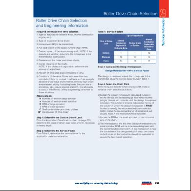
Renold Chain Calculations 3a3z3p
March 2023 0
Fluid Statics 4p6b1y
April 2021 0