Hitecsa cy55
This document was ed by and they confirmed that they have the permission to share it. If you are author or own the copyright of this book, please report to us by using this report form. Report 2z6p3t
Overview 5o1f4z
& View Hitecsa as PDF for free.
More details 6z3438
- Words: 6,781
- Pages: 28
ROOFTOP TYPE UNITS. AIR COOLED CONDENSER. SERIES RXCZ
AIR CONDITIONING
AIR CONDITIONING
ROOFTOP TYPE UNITS AIR COOLED CONDENSER
SERIES: MODELS:
RXCZ 1001, 1201, 1501, 2002, 2402, 3002, 3502, 4002, 4502.
COOLING CAPACITIES OF: 29,0 to 137,0 kW
06.05 Ref. 88397 (En) Rev. 102
1
123456789012345678901234567890121234567890123456789012345678901212345 123456789012345678901234567890121234567890123456789012345678901212345 123456789012345678901234567890121234567890123456789012345678901212345 123456789012345678901234567890121234567890123456789012345678901212345 123456789012345678901234567890121234567890123456789012345678901212345 123456789012345678901234567890121234567890123456789012345678901212345 ROOFTOP TYPE UNITS. AIR CONDITIONING 123456789012345678901234567890121234567890123456789012345678901212345 AIR COOLED CONDENSER. SERIES RXCZ 123456789012345678901234567890121234567890123456789012345678901212345 123456789012345678901234567890121234567890123456789012345678901212345
123456789012345678901234567890121234567890123456789012345678901212345 123456789012345678901234567890121234567890123456789012345678901212345 123456789012345678901234567890121234567890123456789012345678901212345 123456789012345678901234567890121234567890123456789012345678901212345 123456789012345678901234567890121234567890123456789012345678901212345 123456789012345678901234567890121234567890123456789012345678901212345 06.05 Ref. 88397 (En) Rev. 102 123456789012345678901234567890121234567890123456789012345678901212345 2 123456789012345678901234567890121234567890123456789012345678901212345 123456789012345678901234567890121234567890123456789012345678901212345
ROOFTOP TYPE UNITS. AIR COOLED CONDENSER. SERIES RXCZ
AIR CONDITIONING
CONTENTS Page
Description ............................................................................................... 4 Installation flexibility ................................................................................. 5 Construction. Dimensions ................................................................. 6 to 9 Details and dimensions for side supply and return, fresh air etc . 10 to 13 Technical specifications ........................................................................ 14 Cooling capacities ........................................................................ 15 to 17 Fan specifications ......................................................................... 18 to 20 Installation .............................................................................................. 21 Accessories ...................................................................................22 to 28
Hitecsa Aire Acondicionado, S.L.Unipersonal Is participating in Eurovent certification programs
06.05 Ref. 88397 (En) Rev. 102
3
ROOFTOP TYPE UNITS. AIR COOLED CONDENSER. SERIES RXCZ
AIR CONDITIONING
DESCRIPTION General The RXCZ series equipment consists of packaged Rooftop cooling only units, air condenser which are specially recommended for installation on roofs, terraces, and outdoor spaces. The treated air from the interior area may be conducted by the equipment base (downflow return and supply) or by the sides (lateral return and discharge).There are also other variations to suit most site requirements. The units are supplied fully complete with a suitable refrigerant charge for correct operation. This equipment has been designed so that there is no possibility of water entering the air ducts, whether this is condensation, or rain water. The base, which is constructed from sheet profiles, provides structural rigidity for handling or transport without any risk to interior components. Cabinet The structure of these units is completely weatherproof. The base is constructed from very strong steel sheet. The rest of the structure is steel sheet galvanized, that is covered with polyester paint, which is applied in powder form and oven-polymerised at 190 °C, which provides excellent coverage at edges and corners, together with optimum corrosion resistance. The s are internally lined with heat and acoustic insulation. The access s are fitted with quick-action (1/4 turn) catches. The completed unit is in colour RAL 1013. Cooling circuit This includes the following elements: - One or two fully independent circuits. - Indoor and ourdoor coils of copper piping and aluminium fins. - ACR copper refrigerant line. - In-line drying filters. - Schrader valves for high and low pressure service connections. - Expansion system. Compressors One or two 407C hermetic compressors. Models 1501, 3002, 4002 and 4502 are fitted with scroll compressors, which are specially designed for operation under extreme conditions, and include an oil pump. Each compressor include internal thermal protection. A crankase heater is included to provide protection against refrigerant liquid slugging during start-up. Outdoor and indoor coils The coils are constructed of 3/8” non-welded copper piping, which are expanded in aluminium fins. Fans Those of the indoor section are of the double-suction centrifugal type, with static pressure available for application to ducting. They are driven by adjustable belt-pulley transmissions. These fans are low-noise and include pre-lubricated bearings, which are both statically and dynamically balanced.
Those of the outdoor section are of the axial type and are totally sealed, ready for outside weather conditions, with permanent lubrication. They consist of aluminium blades which have been designed to produce reduced noise levels that are inserted in the exterior rotor of a highefficiency motor having IP-54 protection and class F insulation. They are equipped with internal thermal sensors, together with exterior safety grilles. The exterior area air flow is independent for each cooling circuit. Expansion devices The interior section includes thermostatic expansion valves, which are completed with refrigerant distributors. Air filter Polyurethane foam, which is washable and reusable, with a special lattice providing excellent filtration efficiency. Fire classified M1. Operation and control equipment - Controller. - Main switch. - 230/24V transformer and relay system for or coil energising. - ors for operating compressors and fan motors. - Thermal protection for indoor section motors. - H. P. pressostat manual reset. L. P. pressostat automatic reset. - Compressor start-up delay timers. - Terminal strip for control system connections. Options (see pages 22 to 28) - Electrical heater. - Hot water heating coils. - Head pressure controls. - Return or exhaust axial fans. - Enthalpic control economiser. - Thermal control economiser. - Thermo magnetic circuit breakers for indoor and outdoor fans and compressors. - Pretreated coils. - Roof curbs. Electrical power 400V, 3-phase, 50 Hz. OPERATIONAL LIMITS Cooling cycle Air inlet temperature
Dry
Wet
Min.
Max.
Min.
Max.
Indoor coil
19 °C
35 °C
14 °C
21 °C
Outdoor coil
19 °C*
46 °C
–
–
*For temperature of less than 19 °C, it is necessary to use the head pressure control.
06.05 Ref. 88397 (En) Rev. 102
4
ROOFTOP TYPE UNITS. AIR COOLED CONDENSER. SERIES RXCZ
AIR CONDITIONING
INSTALLATION FLEXIBILITY Standard installation (Lower supply and return)
Supply
Return
Possible modifications (factory or on-site).
A
B
Return
Supply
Supply Return
C
Return
Supply
NOTES: 1. In order to modify the air inlet or outlet, the lower side s are changed to the base or vice versa. 2. All s are easily removed using 1/4 turn catches. 3. The units on this page are models 1001, 1202 and 1501. The same is valid for higher models.
06.05 Ref. 88397 (En) Rev. 102
5
ROOFTOP TYPE UNITS. AIR COOLED CONDENSER. SERIES RXCZ
AIR CONDITIONING
CONSTRUCTION. DIMENSIONS MOD. 1001, 1201, 1501
175
99,5
299
550
Return
401 550
Supply
1175 (a)
1160 (a)
176
99,5
Ø
exterior drainage
1650 (a) 25
1700
25
1002 15
2686
953
527
35
227
CONSTRUCTION DETAILS 1. 3/4” male interior drain. 2. Electrical board. 3. Main switch. 4. Electrical power input. (a) Distance between antivibration centres. (b) Distance between central openings for forklift trolleys.
H
1167 135
1020
795
4
503,5
700 (b)
503,5
2543
Supply NOTE: In the lower view, the return and supply ducting dimensions are interior. For the connection of air ducting or canvas, these measurements must be increased by approximately 2 mm on each side, taking into the sheet thickness for the ducting tabs.
1707
1
1237
600
300 100
3
100
2
Return
APPROX. DIMENSIONS (mm)
APPROXIMATE WEIGHT (kg) MODEL
1001
1201
1501
MODEL
1001
1201
1501
Net weight
730
780
820
H (mm)
1460
1530
1530
06.05 Ref. 88397 (En) Rev. 102
6
ROOFTOP TYPE UNITS. AIR COOLED CONDENSER. SERIES RXCZ
AIR CONDITIONING
CONSTRUCTION. DIMENSIONS
99,5 700
Ø
229
1402
15
Return
Supply
99,5
1180 (a)
1556 (a)
99,5
99,5
700
651
exterior drainage
2200 (a) 25
2250
25
MOD. 2002, 2402
2935
953
240
953
55,5
35
55,5
H
1167
4
135
1023
1050
1237
300 100
600
1
100
2 3
778,5
700 (c)
778,5
2945
CONSTRUCTION DETAILS 1. 3/4” male interior drain. 2. Electrical board. 3. Main switch. 4. Electrical power input. (a) Distance between antivibration centres. (b) Distance between crane eared lugs (c) Distance between central openings for forklift trolleys.
318
693
1934 (b)
2257
Supply
Return
NOTE: In the lower view, the return and supply ducting dimensions are interior. For the connection of air ducting or canvas, these measurements must be increased by approximately 2 mm on each side, taking into the sheet thickness for the ducting tabs.
APPROX. DIMENSIONS (mm)
APPROXIMATE WEIGHT (kg) MODEL
2002
2402
MODEL
2002
2402
Net weight
1130
1160
H (mm)
1447
1517
06.05 Ref. 88397 (En) Rev. 102
7
ROOFTOP TYPE UNITS. AIR COOLED CONDENSER. SERIES RXCZ
AIR CONDITIONING
CONSTRUCTION. DIMENSIONS
99,5
229
700
1402
15
Return
Supply
99,5
1180 (a)
1556 (a)
99,5
99,5
700
651
exterior drainage
2200
Ø
25
2250
25
MOD. 3002
2935
1087
953
240
953
55,5
35
55,5
1023
CONSTRUCTION DETAILS 1. 3/4” male interior drain. 2. Electrical board. 3. Main switch. 4. Electrical power supply. (a) Distance between antivibration centres. (b) Distance between crane eared lugs (c) Distance between central openings for forklift trolleys.
4
1828 aprox.
1468 135
1337
1050
100
1
300 100
600
3
1538
2
778,5
700 (c)
778,5
2945 318
1934 (b)
693
2257
Supply
Return
NOTE: In the lower view, the return and supply ducting dimensions are interior. For the connection of air ducting or canvas, these measurements must be increased by approximately 2 mm on each side, taking into the sheet thickness for the ducting tabs.
APPROXIMATE WEIGHT (kg) MODEL
3002
Net weight
1320
06.05 Ref. 88397 (En) Rev. 102
8
ROOFTOP TYPE UNITS. AIR COOLED CONDENSER. SERIES RXCZ
AIR CONDITIONING
CONSTRUCTION. DIMENSIONS MOD. 3502, 4002, 4502 1582
299
700
Ø
25
15
99,5
exterior drainage
700
650
2199
2249
Return
175
exterior drainage 1828 (a)
99,5
25
Supply
1799 (a)
175
35
3977
2
1022
CONSTRUCTION DETAILS 1. 3/4” male interior drain. 2. Electrical board. 3. Main switch. 4. Electrical power supply. (a) Distance between antivibration centres. (b) Distance between crane eared lugs (c) Distance between central openings for forklift trolleys.
365 50
4
135
1
1041
103,5
778,5
1500
700 (c)
778,5
3835 278,5
500,5
3056 (b)
NOTE: In the lower view, the return and supply ducting dimensions are interior. For the connection of air ducting or canvas, these measurements must be increased by approximately 2 mm on each side, taking into the sheet thickness for the ducting tabs.
Supply 2257
100
776
H
1468
1538
3
Return
APPROXIMATE WEIGHT (kg)
APPROX. DIMENSIONS (mm)
MODEL
3502
4202
4502
MODEL
3502
4002
4502
Net weight
1650
1700
1760
H (mm)
1782
1787
1832
06.05 Ref. 88397 (En) Rev. 102
9
ROOFTOP TYPE UNITS. AIR COOLED CONDENSER. SERIES RXCZ
AIR CONDITIONING
VARIOUS OPTIONAL DIMENSIONS MOD. 1001, 1201, 1501
HORIZONTAL SUPPLY & RETURN
328
906
273
157
452
320
800
72
FRESH AIR INTAKE
OPTION 2 EXHAUST FAN (see page 22). 328
800
328
550
524,5
400
531,5
320 225
320
320
72
72
800
OPTION 2 EXHAUST FAN (see page 22)
NOTES: 1. Units with side supply and return include loose sheet profiles for on-site installation. 2. Horizontal supply and return dimensions are identical. 3. The dimensions on the drawings are with sheet profiles already installed.
06.05 Ref. 88397 (En) Rev. 102
10
ROOFTOP TYPE UNITS. AIR COOLED CONDENSER. SERIES RXCZ
AIR CONDITIONING
VARIOUS OPTIONAL DIMENSIONS MOD. 2002, 2402 FRESH AIR INTAKE 1200
328
157
603
320
72
HORIZONTAL SUPPLY & RETURN
1303
273
OPTION 2 EXHAUST FAN (see page 22).
1200
328
328
400
458
320
320 225 320
72
72
1200
OPTION 2 EXHAUST FAN (see page 22)
655
597
NOTES: 1. Units with side supply and return include loose sheet profiles for on-site installation. 2. Horizontal supply and return dimensions are identical. 3. The dimensions on the drawings are with sheet profiles already installed.
06.05 Ref. 88397 (En) Rev. 102
11
ROOFTOP TYPE UNITS. AIR COOLED CONDENSER. SERIES RXCZ
AIR CONDITIONING
VARIOUS OPTIONAL DIMENSIONS MOD. 3002 FRESH AIR INTAKE
HORIZONTAL SUPPLY & RETURN
328
157
603
320
72
1200
1303
273
OPTION 2 EXHAUST FAN (see page 22).
1200
328
328
400
458
320
320 225 320
72
72
1200
OPTION 2 EXHAUST FAN (see page 22)
655
597
NOTES: 1. Units with side supply and return include loose sheet profiles for on-site installation. 2. Horizontal supply and return dimensions are identical. 3. The dimensions on the drawings are with sheet profiles already installed.
06.05 Ref. 88397 (En) Rev. 102
12
ROOFTOP TYPE UNITS. AIR COOLED CONDENSER. SERIES RXCZ
AIR CONDITIONING
VARIOUS OPTIONAL DIMENSIONS MOD. 3502, 4002, 4502 FRESH AIR INTAKE
HORIZONTAL SUPPLY & RETURN
319,5
157
606
420
114
1400
1486
273,5
OPTION 2 EXHAUST FAN (see page 22). 319,5
319,5 114
1400
485
420
341 420 343 420
114
1400
OPTION 2 EXHAUST FAN (see page 22)
762
709
NOTES: 1. Units with side supply and return include loose sheet profiles for on-site installation. 2. Horizontal supply and return dimensions are identical. 3. The dimensions on the drawings are with sheet profiles already installed.
06.05 Ref. 88397 (En) Rev. 102
13
ROOFTOP TYPE UNITS. AIR COOLED CONDENSER. SERIES RXCZ
AIR CONDITIONING
TECHNICAL SPECIFICATIONS MODEL RXCZ Rated cooling capacity POWER SUPPLY
kW
1001
1201
1501
2002
2402
3002
3502
4002
4502
29,0
35,0
43,0
58,0
71,0
85,3
100,0
115,7
137,0
V
400.III
COMPRESSOR Type
Hermetic
Quantity
1
SCROLL 1
1
Hermetic 2
SCROLL Hermetic 2
2
2
SCROLL 2
2
2,47
2,47
INDOOR COIL Type
Aluminium fins and copper tubing 2
m
1,26
1,26
1,26
mm - (")
2,5 - 3/8
1,8 - 3/8
1,8 - 3/8
m2
1,14
1,14
1,50
mm - (")
1,8 - 3/8
1,8 - 3/8
1,8 - 3/8
Motor power
kW
1,1
1,5
2,2
Motor speed
rps
23,3
V
230.III / 400.III
Front surface area Fins size, tube diameter
1,73
1,73
1,8 - 3/8 1,8 - 3/8
1,73
2,47
1,8 - 3/8
1,8 - 3/8
1,8 - 3/8 1,8 - 3/8
OUTDOOR COIL Type Front surface area Fins size, piping diameter
Aluminium fins and copper tubing 2,28
2,28
1,8 - 3/8 1,8 - 3/8
2,85
4,50
1,8 - 3/4
2,5 - 3/8
4,50
4,50
2,1 - 3/8 2,1 - 3/8
INDOOR FAN Type
Voltage (50 Hz ac)
Centrifugal, double inlet 3,0
3,0
4,1
4,1
5,5
5,5
2
4
4
4
OUTDOOR FAN Type
Axial
Quantity
1
1
1
2
2
Diameter Ø
mm
710
800
800
710
800
800
630
710
800
Motor power
kW
0,76
1,25
1,25
0,76
1,25
1,25
0,55
0,76
1,25
Motor speed
rps 230.I
400.III
400.III
230.I
400.III
400.III
230.I
230.I
400.III
1
1
1
2
2
2
2
2
2
7,0
8,4
9,5
6,6
8,4
9,5
10,4
11,3
13,1
34,3
40,9
48,5
57,6
Voltage (50 Hz ac)
V
15
REFRIGERANT Number of circuits 407C charge per circuit
kg
GENERAL SPECIFICATIONS FOR THE ELECTRICAL INSTALLATION Voltage (50 Hz ac) Control circuit Voltage Total input power (cool*)
V
400.III (note 1)
V kW
24 12,0
15,3
19,4
26,5
31,6
Total input current (cool*)
A
21
26
29
45
54
58
70
82
98
Max. input power (cool**)
kW
14,6
18,1
20,5
31,6
37,7
41,0
48,9
57,9
68,7
Max. input current (cool**)
A
25
31
35
54
64
70
83
98
117
Start-up current
A
116
143
190
128
156
205
189
236
270
dB (A)
63
65
65
69
72
73
75
77
78
SOUND PRESSURE (a 5 mt) Unit
Note 1. For availability at 230.3.50 electric supply, see book price in force. To establish the current levels at this voltage, those given in the table must be multiplied by 1.74. * Rated cooling: outdoor air temperature: 35°C. Indoor wet bulb air temperature: 19°C. ** Maximum cooling: outdoor air temperature. 46°C. Indoor wet bulb air temperature: 21°C.
06.05 Ref. 88397 (En) Rev. 102
14
ROOFTOP TYPE UNITS. AIR COOLED CONDENSER. SERIES RXCZ
AIR CONDITIONING
COOLING CAPACITIES
MODEL
RXCZ 1001
RXCZ 1201
RXCZ 1501
1944
2222
2500
Evaporator air flow rate l/s Outdoor air temperature. °C
25
30
35
40
46
25
30
35
40
46
25
30
35
40
46
INDOOR WET BULB TEMPERATURE 15 °C Total capacity Power input Sensible capacity kW
E.dbt.
kW
28,08 26,76 25,05 23,02 20,41 33,89 32,30 30,23 27,78 24,63 41,64 39,68 37,14 34,13 30,26
kW
10,21 10,93 11,66 12,45 13,41 12,66 13,55 14,46 15,43 16,62 14,35 15,36 16,39 17,49 18,84
19 °C
15,06 14,25 13,44 12,55 11,49 18,18 17,20 16,22 15,15 13,87 22,33 21,13 19,92 18,62 17,04
21 °C
18,05 17,25 16,44 15,63 14,64 21,79 20,81 19,84 18,87 17,67 26,77 25,57 24,38 23,18 21,71
23 °C
21,06 20,26 19,44 18,62 17,55 25,41 24,45 23,46 22,48 21,18 31,22 30,04 28,83 27,61 26,02
25 °C
24,05 23,24 22,33 21,33 20,35 29,03 28,05 26,95 25,75 24,56 35,66 34,46 33,11
31,6
30,18
INDOOR WET BULB TEMPERATURE 17 °C Total capacity Power input Sensible capacity kW
E.dbt.
kW
30,19 28,69 27,10 25,14 22,68 36,43 34,63 32,70 30,34 27,37 44,76 42,55 40,18 37,27 33,62
kW
10,48 11,23 12,01 12,83 13,77 12,99 13,93 14,89 15,90 17,08 14,72 15,78 16,88 18,02 19,35
21 °C
15,12 14,31 13,51 12,69 11,70 18,25 17,27 16,31 15,32 14,12 22,42 21,22 20,03 18,82 17,35
23 °C
18,12 17,29 16,50 15,70 14,70 21,87 20,87 19,91 18,94 17,74 26,87 25,64 24,46 23,27 21,80
25 °C
21,12 20,30 19,50 18,69 17,70 25,49 24,50 23,53 22,56 21,37 31,32 30,11 28,91 27,71 26,25
27 °C
24,12 23,31 22,50 21,67 20,55 29,11 28,13 27,15 26,16 24,80 35,77 34,56 33,36
32,1
30,47
40,3
36,51
INDOOR WET BULB TEMPERATURE 19 °C Total capacity
kW
32,11 30,73
29,0
27,15 24,62 38,76 37,09
35,0
32,77 29,72 47,62 45,56
Power input
kW
10,78 11,58
12,2
13,18 14,15 13,37 14,36
15,2
16,34 17,54 15,15 16,27 17,17 18,52 19,87
Sensible capacity kW
E.dbt.
43,0
23 °C
15,19 14,37 13,69 12,75 11,77 18,34 17,35 16,52 15,39 14,21 22,53 21,32 20,30 18,91 17,46
25 °C
18,19 17,37 16,57 15,76 14,78 21,95 20,97 20,00 19,02 17,83 26,97 25,76 24,57 23,37 21,91
27 °C
21,19 20,37 19,57 18,75 17,78 25,58 24,59 23,62 22,63 21,46
31,4
30,21 29,02 27,81 26,36
29 °C
24,20 23,38 22,56 21,75 20,75 29,20 28,22 27,23 26,26 25,05
35,9
34,67 33,46 32,26 30,78
INDOOR WET BULB TEMPERATURE 21 °C Total capacity
kW
33,98 32,78 31,20 29,34 26,85 41,01 39,57 37,65 35,41 32,41 50,39 48,61 46,26 43,50 39,81
Power input
kW
11,08 11,93 12,77 13,56 14,59 13,73 14,79 15,83 16,82 18,09 15,56 16,76 17,94 19,06 20,50
25 °C
15,26 14,45 13,64 12,82 11,84 18,42 17,44 16,46 15,48 14,29 22,64 21,42 20,22 19,02 17,56
27 °C
18,25 17,45 16,64 15,82 14,83 22,03 21,06 20,08 19,10 17,90 27,06 25,87 24,67 23,47 22,00
29 °C
21,26 20,45 19,63 18,82 17,84 25,66 24,68 23,70 22,71 21,54
31 °C
24,25 23,45 22,64 21,82 20,83 29,27 28,31 27,32 26,34 25,14 35,96 34,78 33,57 32,36 30,89
Sensible capacity kW
E.dbt.
NOTES:
31,5
30,33 29,11 27,90 26,46
CORRECTION FACTORS
1. Cooling capacities are net, after deducting the indoor motor heat.
% air flow rate.
80
90
110
120
2. E.dbt. dry bulb entering air temperature.
Total capacity.
0,94
0,97
1,03
1,05
Sensible heat.
0,92
0,96
1,04
1,03
Input.
0,96
0,98
1,02
1,03
06.05 Ref. 88397 (En) Rev. 102
15
ROOFTOP TYPE UNITS. AIR COOLED CONDENSER. SERIES RXCZ
AIR CONDITIONING
COOLING CAPACITIES MODEL
RXCZ 2002
RXCZ 2402
RXCZ 3002
3111
3555
3888
Evaporator air flow rate l/s Outdoor air temperature. °C
25
30
35
40
46
25
30
35
40
46
25
30
35
40
46
INDOOR WET BULB TEMPERATURE 15 °C Total capacity
kW
56,16 53,52 50,09 46,04 40,82 68,75 65,52 61,32 56,36 49,97 82,59 78,71 73,67 67,71 60,03
Power input
kW
22,14 23,70 25,29 26,99 29,08 26,40 28,26 30,16 32,19 34,67 28,69 30,71 32,77 34,98 37,68
19 °C
30,14 28,52 26,89 25,12 23,00 36,88 34,90 32,90 30,74 28,14 45,19 42,76 40,31 37,67 34,49
21 °C
36,13 34,51 32,89 31,28 29,29 44,21 42,23 40,25 38,28 35,84 54,17 51,75 49,32 46,90 43,92
23 °C
42,13 40,53 38,90 37,26 35,11 51,56 49,60 47,60 45,60 42,96 63,18 60,78 58,33 55,88 52,65
25 °C
48,12 46,51 44,68 42,68 40,73 58,89 56,91 54,68 52,23 49,84 72,16 69,74 67,00
Sensible capacity kW
E.dbt.
64,0
61,07
INDOOR WET BULB TEMPERATURE 17 °C Total capacity
kW
60,38 57,39 54,20 50,27 45,35 73,91 70,25 66,34 61,54 55,52 88,80 84,40 79,71 73,94 66,70
Power input
kW
22,72 24,36 26,05 27,82 29,87 27,09 29,05 31,06 33,17 35,62 29,44 31,57 33,75 36,05 38,70
21 °C
30,25 28,63 27,03 25,40 23,42 37,02 35,04 33,08 31,08 28,65 45,36 42,94 40,54 38,09 35,11
23 °C
36,26 34,61 33,01 31,41 29,42 44,37 42,35 40,39 38,43 36,00 54,37 51,89 49,50 47,09 44,11
25 °C
42,26 40,63 39,01 37,40 35,43 51,72 49,72 47,74 45,76 43,35 63,37 60,92 58,50 56,07 53,12
27 °C
48,27 46,64 45,02 43,37 41,12 59,07 57,07 55,09 53,07 50,32 72,38 69,93 67,51
Sensible capacity kW
E.dbt.
65,0
61,66
79,9
72,42
INDOOR WET BULB TEMPERATURE 19 °C Total capacity
kW
64,23 61,46
58,0
54,31 49,24 78,63 75,23
71,0
66,48 60,28 94,46 90,38
Power input
kW
23,38 25,12
26,5
28,59 30,67 27,88 29,95
31,6
34,09 36,58 30,30 32,55 34,34 37,05 39,75
Sensible capacity kW
E.dbt.
85,3
23 °C
30,40 28,76 27,39 25,51 23,56 37,20 35,20 33,52 31,22 28,83 45,58 43,13 41,08 38,26 35,33
25 °C
36,40 34,77 33,15 31,54 29,57 44,54 42,54 40,57 38,59 36,18 54,58 52,13 49,71 47,29 44,34
27 °C
42,41 40,76 39,16 37,53 35,57 51,90 49,88 47,92 45,92 43,53
63,6
61,12 58,72 56,27 53,34
29 °C
48,42 46,78 45,15 43,53 41,53 59,25 57,25 55,25 53,27 50,82
72,6
70,15 67,70 65,27 62,27
INDOOR WET BULB TEMPERATURE 21 °C Total capacity
kW
67,96 65,57 62,39 58,67 53,70 83,20 80,27 76,38 71,83 65,74 99,95 96,43 91,76 86,29 78,98
Power input
kW
24,02 25,87 27,68 29,41 31,64 28,64 30,85 33,01 35,07 37,73 31,13 33,53 35,87 38,12 41,00
25 °C
30,54 28,91 27,29 25,66 23,69 37,38 35,38 33,40 31,40 28,99 45,80 43,35 40,92 38,48 35,53
27 °C
36,52 34,92 33,29 31,67 29,68 44,68 42,73 40,74 38,75 36,32 54,76 52,36 49,92 47,48 44,51
29 °C
42,54 40,92 39,29 37,65 35,70 52,05 50,08 48,08 46,08 43,69
31 °C
48,53 46,93 45,30 43,66 41,68 59,38 57,43 55,43 53,43 51,00 72,77 70,37 67,92 65,47 62,50
Sensible capacity kW
E.dbt.
NOTES:
63,8
61,36 58,91 56,46 53,54
CORRECTION FACTORS
1. Cooling capacities are net, after deducting the indoor motor heat.
% air flow rate.
80
90
110
120
2. E.dbt. dry bulb entering air temperature.
Total capacity.
0,94
0,97
1,03
1,05
Sensible heat.
0,92
0,96
1,04
1,03
Input.
0,96
0,98
1,02
1,03
06.05 Ref. 88397 (En) Rev. 102
16
ROOFTOP TYPE UNITS. AIR COOLED CONDENSER. SERIES RXCZ
AIR CONDITIONING
COOLING CAPACITIES MODEL
RXCZ 3502
RXCZ 4002
RXCZ 4502
5000
5555
6111
Evaporator air flow rate l/s Outdoor air temperature. °C
25
30
35
40
46
25
30
35
40
46
25
30
35
40
46
INDOOR WET BULB TEMPERATURE 15 °C Total capacity
kW
96,83 92,28 86,37 79,38 70,38 112,03 106,76 99,93 91,84 81,43 132,65 126,42 118,32 108,75 96,42
Power input
kW
34,18 36,58 39,04 41,66 44,88 40,51 43,36 46,27 49,38 53,19 48,10 51,49 54,94 58,64 63,17
19 °C
53,24 50,38 47,50 44,38 40,63 61,29 58,00 54,68 51,09 46,77 72,71 68,82 64,87 60,62 55,50
21 °C
63,82 60,96 58,11 55,26 51,75 73,47 70,18 66,90 63,61 59,57 87,17 83,27 79,37 75,47 70,68
23 °C
74,43 71,60 68,72 65,83 62,02 85,69 82,43 79,10 75,78 71,40 101,66 97,80 93,86 89,91 84,72
25 °C
85,01 82,16 78,94 75,41 71,95 97,87 94,58 90,87 86,81 82,83 116,11 112,21 107,82 103,0 98,27
Sensible capacity kW
E.dbt.
INDOOR WET BULB TEMPERATURE 17 °C Total capacity
kW 104,10 98,94 93,44 86,68 78,19 120,44 114,48 108,11 100,29 90,47 142,6 135,6 128,01 118,75 107,12
Power input
kW
35,07 37,60 40,20 42,94 46,10 41,56 44,56 47,65 50,89 54,64 49,35 52,92 56,58 60,43 64,89
21 °C
53,44 50,59 47,76 44,87 41,37 61,52 58,23 54,98 51,66 47,62 72,99 69,09 65,23 61,29 56,50
23 °C
64,05 61,13 58,31 55,48 51,97 73,74 70,38 67,13 63,87 59,83 87,49 83,50 79,65 75,78 70,99
25 °C
74,66 71,77 68,92 66,06 62,59 85,95 82,62 79,34 76,05 72,05 101,97 98,03 94,13 90,23 85,48
27 °C
85,27 82,39 79,53 76,61 72,64 98,17 94,84 91,56 88,20 83,62 116,47 112,53 108,63 104,6 99,21
Sensible capacity kW
E.dbt.
INDOOR WET BULB TEMPERATURE 19 °C Total capacity
kW 110,74 105,96 100,0 93,64 84,90 128,13 122,60 115,7 108,34 98,23 151,7 145,2 137,0 128,3 116,32
Power input
kW
Sensible capacity kW
E.dbt.
36,09 38,77
40,9
44,13 47,35 42,78 45,95
48,5
52,30 56,12 50,80 54,56 57,57 62,11 66,64
23 °C
53,70 50,81 48,39 45,07 41,62 61,82 58,50 55,71 51,89 47,91 73,35 69,41 66,10 61,56 56,85
25 °C
64,30 61,42 58,57 55,71 52,23 74,02 70,71 67,42 64,13 60,13 87,82 83,89 79,99 76,09 71,34
27 °C
74,92 72,01 69,18 66,29 62,85 86,25 82,89 79,64 76,32 72,35 102,3 98,35 94,49 90,55 85,84
29 °C
85,53 82,65 79,76 76,90 73,37 98,46 95,14 91,82 88,53 84,46 116,8 112,88 108,94 105,03 100,21
INDOOR WET BULB TEMPERATURE 21 °C Total capacity
kW 117,18 113,05 107,57 101,16 92,59 135,6 130,80 124,46 117,05 107,13 160,5 154,9 147,4 138,6 126,9
Power input
kW
37,08 39,94 42,73 45,40 48,84 43,94 47,33 50,65 53,81 57,88 52,18 56,21 60,14 63,90 68,74
25 °C
53,96 51,07 48,21 45,33 41,86 62,12 58,80 55,50 52,19 48,18 73,70 69,76 65,85 61,92 57,17
27 °C
64,51 61,68 58,81 55,94 52,44 74,26 71,01 67,70 64,40 60,37 88,11 84,25 80,33 76,41 71,62
29 °C
75,15 72,29 69,41 66,52 63,07 86,51 83,22 79,90 76,58 72,61 102,6 98,74 94,80 90,86 86,15
31 °C
85,73 82,91 80,02 77,13 73,63 98,69 95,44 92,12 88,80 84,76 117,09 113,24 109,30 105,35 100,57
Sensible capacity kW
E.dbt.
NOTES:
CORRECTION FACTORS
1. Cooling capacities are net, after deducting the indoor motor heat.
% air flow rate.
80
90
110
120
2. E.dbt. dry bulb entering air temperature.
Total capacity.
0,94
0,97
1,03
1,05
Sensible heat.
0,92
0,96
1,04
1,03
Input.
0,96
0,98
1,02
1,03
06.05 Ref. 88397 (En) Rev. 102
17
ROOFTOP TYPE UNITS. AIR COOLED CONDENSER. SERIES RXCZ
AIR CONDITIONING
FAN CHARACTERISTIC CURVES AIR FLOW RATE. STATIC PRESSURE
Mod. 1001
Rated flow
300
Fan pulley (fixed) ø 180 mm. Motor pulley (adjust.) ø 75-100 mm.
275 M
250
ot
Static pressure Pa
or
225
1,
1
kW
/1
1/
2
200 1/2
175
t.o.
755
CV
1/m
0t
in
150 1t
.o.
125
.o.
77
01
/m
72
51
in
/m
in
100 75 5.800
Mod. 1201
6.200
7.000
7.400
7.800
8.200
m3/h
8.600
Rated flow
300
Fan pulley (fixed) ø 180 mm. Motor pulley (adjust.) ø 75-125 mm.
Mo
275
tor
1,5
kW
/2
250 Static pressure Pa
6.600
CV
225 200 0 v. a. 8 90 r .p.m 1/2 . v.a. 870 r.p.m . 1v .a. 850 r.
175 150
11
/2 v .a.
125
830
r.p. m
.
p.m
100
.
75 7.800
Mod. 1501
8.200
8.600
9.000
9.400
9.800
10.200
10.600
m3/h
Rated flow
300
Fan pulley (fixed) ø 160 mm. Motor pulley (adjust.) ø 100-125 mm.
275
Static pressure Pa
250 1 1/2
225
v.a. 9
Mo
70 r.
200
p.m.
tor
2,2
kW
/3
175
2 v.
CV
a. 9
150
21
/2 v .a.
125
3v .a.
100
40 r .p.m
.
910
r.p. m
.
88
0r .p.
m.
75 7.800
8.200
8.600
9.000
9.400
9.800
10.200
10.600
m3/h
06.05 Ref. 88397 (En) Rev. 102
18
ROOFTOP TYPE UNITS. AIR COOLED CONDENSER. SERIES RXCZ
AIR CONDITIONING
FAN CHARACTERISTIC CURVES AIR FLOW RATE. STATIC PRESSURE
Mod. 2002
Rated flow
275
Fan pulley (fixed) ø 200 mm. Motor pulley (adjust.) ø 100-125 mm.
250 Mo
11 1v 1/2 .a. /2 v.a 2v v.a 7 8 .8 .a. .7 5r 10 60 .p. 74 r.p m r 5 . p.m . .m r.p 21 . .m . /2 . v.a .7 20 r.p .m .
200
150
V 4C
175
W/
3k
Static pressure Pa
tor
225
125 100 75 50 9.400
Mod. 2402
10.200
11.000
11.800
12.600
13.400
14.200
15.000
m3/h
Rated flow
225
Fan pulley (fixed) ø 200 mm. Motor pulley (adjust.) ø 100-125 mm.
200
Static pressure Pa
m.
5r .p. m. 0r .p. m.
72
V
v.a .
5r .p.
78
76
4C
/2
125
74
v.a .
W/
21
/2
3k
150
1v .a.
11
tor
2v .a.
Mo
175
0r .p.
1/2
m.
100
v.a .
81
0r .p.
m.
75 50 25 0 9.600
Mod. 3002
10.400
11.200
12.000
12.800
13.600
14.400
15.200
m3/h
Rated flow
300
Fan pulley (fixed) ø 180 mm. Motor pulley (adjust.) ø 100-125 mm.
275
1v .a.
225
875
/5 kW 4,1 tor Mo
r.p. m
.
200
2v .a.
175
830 /2
125
/2
r.p. m
.
21
150
11
v.a .
85
5r .p.
m.
81
3v .a.
100
v.a .
CV 1/2
Static pressure Pa
250
0r .p.
m.
79
0r .p.
m.
75 11.600
12.400
13.200
14.000
14.800
15.600
16.400
17.200
m3/h
06.05 Ref. 88397 (En) Rev. 102
19
ROOFTOP TYPE UNITS. AIR COOLED CONDENSER. SERIES RXCZ
AIR CONDITIONING
FAN CHARACTERISTIC CURVES AIR FLOW RATE. STATIC PRESSURE
Mod. 3502
Rated flow
300
Fan pulley (fixed) ø 224 mm. Motor pulley (adjust.) ø 100-125 mm.
275
/2 v .a.
225
2 v.
a. 6
75
200
705
.
r.p. m
/2 v .a.
3 v.
a. 6
35
150
655
CV
.
21
175
r.p. m
,5 /5 kW
Static pressure Pa
11
1 4, or ot M
250
r.p. m
.
r.p. m
.
125 100 75 15.000
Mod. 4002
16.000
17.000
18.000
19.000
20.000
21.000
22.000
m3/h
Rated flow
275
Fan pulley (fixed) ø 224 mm. Motor pulley (adjust.) ø 100-138 mm.
250 M ot or 5, 5k 1v 2v W .a. .a. /7 785 750 1/ r.p. r.p. 2C m m 21 . . V /2 v .a. 735 r.p. m. 31 /2 v .a. 675 r.p. m.
Static pressure Pa
225 200 175 150 125 100 75 50 17.000
Mod. 4502
18.000
19.000
20.000
21.000
22.000
23.000
24.000
m3/h
Rated flow
275
Fan pulley (fixed) ø 224 mm. Motor pulley (adjust.) ø 100-138 mm.
250
Static pressure Pa
225 200 2v .a.
175
1v M .a. ot 78 or 5r 5, .p. 5 m. 21 kW /2 /7 v.a 1/ .7 31 2 35 /2 CV r.p v.a .m .6 . 95 r.p .m .
75
0r .p.
m.
150 125 100 75 50 19.000
20.000
21.000
22.000
23.000
24.000
25.000
26.000
m3/h
06.05 Ref. 88397 (En) Rev. 102
20
ROOFTOP TYPE UNITS. AIR COOLED CONDENSER. SERIES RXCZ
AIR CONDITIONING
INSTALLATION
1300
RXCZ 1001, 1201, 1501
SERVICE AREA
X. When the unit includes the electrical heating option or hot water coil, or it is intended to include these at a future date, this service area level should be as indicated.
X
1300
MODEL
X (mm)
1001, 1201, 1501
1500
2002, 2402, 3002
1800
3502, 4002, 4502
2100
1300
Otherwise leave 1,300 mm.
RXCZ 3502, 4002, 4502 1300
1300
RXCZ 2002, 2402, 3002
X
X
1300
1300
1300
1300
WEIGHT DISTRIBUTION In the case of using four shock absorbers, distribute 3 between 1 and 5 ; 4 between 2 and 6 . APPROXIMATE WEIGHT (kg) MODEL
1
2
3
4
1001
139
139
117
1201
148
148
125
5
6
Total
124
102
109
730
133
109
117
780
1501
156
156
131
139
115
123
820
2002
215
215
181
192
157
170
1130
2402
215
215
181
192
157
170
1130
3002
251
251
226
224
200
198
1350
3502
445
363
272
231
181
158
1650
4002
459
374
281
238
187
161
1700
4502
475
387
290
246
194
168
1760
Z
Y 2
4
6
Electric (3502-4502)
X 1
3
5
Electric (1001-3002)
AIR FILTERS FILTER DIMENSIONS (mm)* MODEL
HEIGHT
WIDE
1001, 1201, 1501
1055
465
2002, 2402, 3002
1055
595
3502, 4002, 4502
1355
655
* Each models uses three filters. 06.05 Ref. 88397 (En) Rev. 102
21
ROOFTOP TYPE UNITS. AIR COOLED CONDENSER. SERIES RXCZ
AIR CONDITIONING
ACCESSORIES RETURN AND EXHAUST FANS Normally associated with a “free-cooling” economizer system, they can however, be installed independently in the return to increase available pressure for the main fan or to simply operate as a single exhaust. Axial or centrifugal fans are used based on the required static pressure.
FAN
MODELS
POSITION
Ø
Quantity
1001, 1201, 1501
500
2
Side / base
2002, 2402, 3002
560
2
Side / base
3502, 4002, 4502
630
2
Side / base
CONFIGURATION 1
X
Return & exhaust fan
V Y
Return & exhaust
Side supply (conversion by installer)
W
Standard Supply
CONFIGURATION 2
X
CONSTRUCTION DETAILS V. Mixing damper. W. Exhaust damper. X. Fresh air damper. Y. Return fan. Z. Exhaust fan. Note: Centrifugal type return fan (consult).
V W Side supply (conversion by installer) Y
Standard Supply
CONFIGURATION 3
X
SOLUTION*
FAN CONFIGURATION Extraction or return
Standard
2-3
A
2-3
B
1
C
1
* See page 5 for solutions A, B, and C.
Z
V Side supply (conversion by installer)
Return
Standard Supply
06.05 Ref. 88397 (En) Rev. 102
22
ROOFTOP TYPE UNITS. AIR COOLED CONDENSER. SERIES RXCZ
AIR CONDITIONING
ACCESSORIES RETURN AND EXHAUST FANS p [Pa]
H [mm WG]
120
12
100
10
IP-45 C: 5F m 400V A: CIF
80
8
-40/+70 °C
60
6
40
4
20
2
0
0
MOD. 1001, 1201, 1501 Plate information. V: 230 D Hz: 50 A: 1.1 kW: 0.24 rpm: 880
(Optional two fans)
3
230V
50 Hz
U
I
P1
n
Q
LWA
(V)
(A)
(W)
(rpm)
(m3/h)
dB
1
230
0,94
210
920
5670
67
2
230
1,15
260
850
3
230
1,31
300
785
MOD. 2002, 2402, 3002
(Optional two fans)
IP-54 C: 9F m 400V A: CIF -40/+70 °C
HRB/6 - 500/30
230V
50 Hz
U
I
P1
n
Q
LWA
(V)
(A)
(W)
(rpm)
(m3/h)
dB
1
230
1,37
320
925
7740
72
2
230
1,75
415
855
3
230
2,16
500
780
MOD. 3502, 4002, 4502
(Optional two fans)
IP-45 C: 12F m 400V A: CIF -40/+70 °C
0V
1 0
1000
2000
3000
4000
5000
6000 Q [m3/h]
0
0.28
0.56
0.83
1.11
1.39
1.67 Q [l/s]
p [Pa]
H [mm WG]
160
16
140
14
120
12
100
10
80
8
60
6
40
4
20
2
0
0
Ø 560 mm 3
2
23
0V
1 0
1000 2000 3000 4000 5000 6000 7000 8000 Q [m3/h]
0
0.28 0.56 0.83 1.11 1.39 1.67 1.94 2.22 Q [l/s]
p [Pa]
H [mm WG]
120
12
100
10
80
8
60
6
40
4
20
2
0
0
Ø 630 mm
3
2
0
23
Plate information. V: 230 D Hz: 50 A: 1.9 kW: 0.55 rpm: 832
23
2
HRB/6 - 500/30
Plate information. V: 230 D Hz: 50 A: 1.8 kW: 0.40 rpm: 830
Ø 500 mm
230V
50 Hz
U
I
P1
n
Q
LWA
(V)
(A)
(W)
(rpm)
(m3/h)
dB
1
230
1,98
465
870
11000
77
2
230
2,50
575
780
3
230
2,55
595
760
V
HRB/6 - 500/30
1 0
2000
4000
6000
8000
0
0.56
1.11
1.67
2.22
10000 12000 Q [m3/h] 2.78
3.33 Q [l/s]
Note: This information is for one fan. 06.05 Ref. 88397 (En) Rev. 102
23
ROOFTOP TYPE UNITS. AIR COOLED CONDENSER. SERIES RXCZ
AIR CONDITIONING
ACCESSORIES HEAD PRESSURE CONTROL
REGULATOR
MODEL
FAN
DIRECT DRIVE FAN *
Quantity
Amps/Unit
Diameter
Quantity
Model
Volts
kW
Amps.
1001
1
4
630
1
FE071
1201
1
5
800
1
FE080
230.I
0,76
3
400.III
1,25
4
1501
1
5
800
1
FE080
400.III
1,25
4
2002
2
4
710
2
FE071
230.I
0,76
3
2402
1
5
800
2
FC080
400.III
1,25
4
3002
2
5
800
2
FE080
400.III
1,25
4
3502
2
6
630
4
HRB630
230.I
0,55
2
4002
2
8
710
4
FE071
230.I
0,76
3
4502
2
5
800
4
FE080
400.III
1,25
4
* Fan motor assembly type when head pressure control is mounted. The standard model 2402 unit is fitted with motor-driven fan FE080. The standard units can operate at exterior temperatures in excess of 19 °C. With this electronic control, it can operate down to -10 °C.
Air Filter Indoor Coil Electrical heaters
ELECTRICAL HEATERS
MODEL
kW
1001, 1201, 1501
13,5 + 13,5
1001, 1201, 1501
18,5 + 13,5
1501, 2002, 2402
18,0 + 18,0
2402, 3002, 3502
22,5 + 22,5
3502, 4002, 4502
31,5 + 31,5
HOT WATER HEATING COILS MODEL
kW
1001
71
1201
81
1501
83
2000
109
2400
119
3000
128
3505
160
4000
186
4500
191
Air Filter Indoor Coil Hot water Coil
06.05 Ref. 88397 (En) Rev. 102
24
ROOFTOP TYPE UNITS. AIR COOLED CONDENSER. SERIES RXCZ
AIR CONDITIONING
ACCESSORIES “FREE-COOLING” ECONOMIZER The “free-cooling” economizer takes advantage of the temperature and humidity conditions (enthalpic comparison) or only temperature (thermal comparison) of the outside air with respect to the return air and uses it to condition the areas requiring cooling in function of the value set by the system control, making whatever mixes are necessary and may even shutdown the compressors, with the corresponding energy savings. The system consists of an electronic control centre which receives information from the exterior and return air sensors by means of a continuous comparison (enthalpic or thermal), and feeding the actuators for the corresponding gates, producing a 100% proportional regulation.
OPTION A (basic) - Fresh air damper. - Mixing damper.
OPTION B (complete) - Fresh air damper. - Mixing damper. - Return fan. - Exhaust damper.
Return Fan in Base
3 9 6
1
7
CONSTRUCTION DETAILS 1. Outdoor air sensor. 2. Return air sensor. 3. Fresh air damper. 4. Return air damper. 5. Return/exhaust fan. 6. Connector. 7. controller. 8. Actuator. 9. Rain protection 10. Supply sensor.
Side Return Fan
5
8
2
4
10
06.05 Ref. 88397 (En) Rev. 102
25
ROOFTOP TYPE UNITS. AIR COOLED CONDENSER. SERIES RXCZ
AIR CONDITIONING
ACCESSORIES
“ARIA” ELECTRONIC CONTROL
(For RXCZ without economiser)
“Aria” is a microprocessor-controlled regulator consisting of two integrated elements: a TERMINAL for location in the controlled environment, together with a POWER CARD which is housed in the machine’s electrical board. The connection between the terminal and the power board requires only a pair of wires. Power Board Terminal
Maximum: 150 metres
screen display
The terminal’s side keys provide access to the various functions: MODE: Selects Cool, Heat, Auto, Fan or Off. FAN: Determines operation of Fan. SET: Adjusts set points: Comfort, Absence, Night-time. CLOCK: Time clock and phases. With clock (consult availability). HOLD: Various function and parameter output management. RESUME: Reset alarms, programming phase output. Front keys: Permit set point modification.
The LCD shows environmental temperature, the COOL/HEAT function, fan operating mode, set point category: presence, absence, night-time and comfort etc. Characteristics - Liquid crystal Display (LCD). - Option: remote temperature sensor. - Option: Clock for timer programming. - Green multiple information LED (on power card). Applications 1. STAND-ALONE type: one controller per machine. 2. LAN (Local Area Network): permits control of up to 30 units, each unit with its associated terminal with LAN output, centralising all information and control in a pCO terminal (consult).
06.05 Ref. 88397 (En) Rev. 102
26
ROOFTOP TYPE UNITS. AIR COOLED CONDENSER. SERIES RXCZ
AIR CONDITIONING
ACCESSORIES
THERMOSTAT
(Alternative to "ARIA" controler)
Microprocessor-controlled 24 Vac electronic thermostat, which is internally configurable and connected to the machine by cable to regulate the equipment functions, one or two stage cooling, together with one or two stage heating. The environmental thermostat permits individual machine control and automatic start-up/shutdown, cooling and heating (electrical heating elements or hot water battery), continuous or automatic ventilation (with the corresponding function). The liquid crystal screen displays the environmental temperature, set point, operating mode and ventilation mode etc, together with their associated icons.
1
6
2
5
Duct sensor Wall sensor 3
4
FUNCTIONS 1. Mode. 2. Ventilation. 3. Temperature reduction. 4. Temperature increase. 5. Day/night set point (not used) 6. Exterior temperature.
External sensor (consult)
(only with external sensor as an option). The termostat will accept wall, duct or external sensors. The application of a duct sensor requires the wall sensor. Note: Up to six sensors can be used on large premises. The system calculates the arithmetic average of the temperatures detected by each one.
PCO TERMINAL For “Rooftop” unit control when this incorporates “free-cooling”. The pCO has several control levels available and accessible using the corresponding s. It is employed to configure the equipment at the factory and for -modification of the basic operating parameters. The LCD shows the COOL/HEAT operation, environmental temperature, the time (with clock card) and alarms etc.
06.05 Ref. 88397 (En) Rev. 102
27
ROOFTOP TYPE UNITS. AIR COOLED CONDENSER. SERIES RXCZ
AIR CONDITIONING
ACCESSORIES
LAN (Local Area Network) This permits control of up to fifteen units using a single pCO terminal. In this case, the basic electronic board incorporates an additional LAN addressing card, with the clock option. 1
15 units maximum 2 CONSTRUCTION DETAILS 1. Shielded, twisted cable, 2-pairs. 2. Shielded, twisted cable, 3-pairs. 3. Connector. 4. Telephone cable. 5. terminal.
COILS IN WITH AMBIENT AIR Pretreated coils (blue fins).
3 4 5
VARIATIONS FROM STANDARD PRODUCTION – High pressure pressostat automatic reset. – Main fan off during defrost. • Special electric s (fault indication, etc). • Return & supply from the top. • Connection to a PC without supervisor.
OTHER ACCESSORIES
• Connection to a PC with supervisor.
Air quality sensor.
• LEAD TIME TO BE CONSULTED.
Clogged filter detector.
* SPECIAL REQUIREMENTS TO BE CONSULTED.
Smoke detector. Clock board. Roof curbs. Compressor sound jacket. Commissioning.
12345678901234567890123456789012123456789012345678901234567890121234 12345678901234567890123456789012123456789012345678901234567890121234 12345678901234567890123456789012123456789012345678901234567890121234 12345678901234567890123456789012123456789012345678901234567890121234 06.05 Ref. 88397 (En) Rev. 102 12345678901234567890123456789012123456789012345678901234567890121234 06.05 Ref. 88397 (En) Rev. 102 12345678901234567890123456789012123456789012345678901234567890121234 28 12345678901234567890123456789012123456789012345678901234567890121234 12345678901234567890123456789012123456789012345678901234567890121234 D.L.: B-4.790-03
Gràfiques Ferpala s.l. Barcelona 4, bis 08800 Vilanova i la Geltrú Tel. 93 893 70 11
Specifications subject to change without previous notice.
AIR CONDITIONING
AIR CONDITIONING
ROOFTOP TYPE UNITS AIR COOLED CONDENSER
SERIES: MODELS:
RXCZ 1001, 1201, 1501, 2002, 2402, 3002, 3502, 4002, 4502.
COOLING CAPACITIES OF: 29,0 to 137,0 kW
06.05 Ref. 88397 (En) Rev. 102
1
123456789012345678901234567890121234567890123456789012345678901212345 123456789012345678901234567890121234567890123456789012345678901212345 123456789012345678901234567890121234567890123456789012345678901212345 123456789012345678901234567890121234567890123456789012345678901212345 123456789012345678901234567890121234567890123456789012345678901212345 123456789012345678901234567890121234567890123456789012345678901212345 ROOFTOP TYPE UNITS. AIR CONDITIONING 123456789012345678901234567890121234567890123456789012345678901212345 AIR COOLED CONDENSER. SERIES RXCZ 123456789012345678901234567890121234567890123456789012345678901212345 123456789012345678901234567890121234567890123456789012345678901212345
123456789012345678901234567890121234567890123456789012345678901212345 123456789012345678901234567890121234567890123456789012345678901212345 123456789012345678901234567890121234567890123456789012345678901212345 123456789012345678901234567890121234567890123456789012345678901212345 123456789012345678901234567890121234567890123456789012345678901212345 123456789012345678901234567890121234567890123456789012345678901212345 06.05 Ref. 88397 (En) Rev. 102 123456789012345678901234567890121234567890123456789012345678901212345 2 123456789012345678901234567890121234567890123456789012345678901212345 123456789012345678901234567890121234567890123456789012345678901212345
ROOFTOP TYPE UNITS. AIR COOLED CONDENSER. SERIES RXCZ
AIR CONDITIONING
CONTENTS Page
Description ............................................................................................... 4 Installation flexibility ................................................................................. 5 Construction. Dimensions ................................................................. 6 to 9 Details and dimensions for side supply and return, fresh air etc . 10 to 13 Technical specifications ........................................................................ 14 Cooling capacities ........................................................................ 15 to 17 Fan specifications ......................................................................... 18 to 20 Installation .............................................................................................. 21 Accessories ...................................................................................22 to 28
Hitecsa Aire Acondicionado, S.L.Unipersonal Is participating in Eurovent certification programs
06.05 Ref. 88397 (En) Rev. 102
3
ROOFTOP TYPE UNITS. AIR COOLED CONDENSER. SERIES RXCZ
AIR CONDITIONING
DESCRIPTION General The RXCZ series equipment consists of packaged Rooftop cooling only units, air condenser which are specially recommended for installation on roofs, terraces, and outdoor spaces. The treated air from the interior area may be conducted by the equipment base (downflow return and supply) or by the sides (lateral return and discharge).There are also other variations to suit most site requirements. The units are supplied fully complete with a suitable refrigerant charge for correct operation. This equipment has been designed so that there is no possibility of water entering the air ducts, whether this is condensation, or rain water. The base, which is constructed from sheet profiles, provides structural rigidity for handling or transport without any risk to interior components. Cabinet The structure of these units is completely weatherproof. The base is constructed from very strong steel sheet. The rest of the structure is steel sheet galvanized, that is covered with polyester paint, which is applied in powder form and oven-polymerised at 190 °C, which provides excellent coverage at edges and corners, together with optimum corrosion resistance. The s are internally lined with heat and acoustic insulation. The access s are fitted with quick-action (1/4 turn) catches. The completed unit is in colour RAL 1013. Cooling circuit This includes the following elements: - One or two fully independent circuits. - Indoor and ourdoor coils of copper piping and aluminium fins. - ACR copper refrigerant line. - In-line drying filters. - Schrader valves for high and low pressure service connections. - Expansion system. Compressors One or two 407C hermetic compressors. Models 1501, 3002, 4002 and 4502 are fitted with scroll compressors, which are specially designed for operation under extreme conditions, and include an oil pump. Each compressor include internal thermal protection. A crankase heater is included to provide protection against refrigerant liquid slugging during start-up. Outdoor and indoor coils The coils are constructed of 3/8” non-welded copper piping, which are expanded in aluminium fins. Fans Those of the indoor section are of the double-suction centrifugal type, with static pressure available for application to ducting. They are driven by adjustable belt-pulley transmissions. These fans are low-noise and include pre-lubricated bearings, which are both statically and dynamically balanced.
Those of the outdoor section are of the axial type and are totally sealed, ready for outside weather conditions, with permanent lubrication. They consist of aluminium blades which have been designed to produce reduced noise levels that are inserted in the exterior rotor of a highefficiency motor having IP-54 protection and class F insulation. They are equipped with internal thermal sensors, together with exterior safety grilles. The exterior area air flow is independent for each cooling circuit. Expansion devices The interior section includes thermostatic expansion valves, which are completed with refrigerant distributors. Air filter Polyurethane foam, which is washable and reusable, with a special lattice providing excellent filtration efficiency. Fire classified M1. Operation and control equipment - Controller. - Main switch. - 230/24V transformer and relay system for or coil energising. - ors for operating compressors and fan motors. - Thermal protection for indoor section motors. - H. P. pressostat manual reset. L. P. pressostat automatic reset. - Compressor start-up delay timers. - Terminal strip for control system connections. Options (see pages 22 to 28) - Electrical heater. - Hot water heating coils. - Head pressure controls. - Return or exhaust axial fans. - Enthalpic control economiser. - Thermal control economiser. - Thermo magnetic circuit breakers for indoor and outdoor fans and compressors. - Pretreated coils. - Roof curbs. Electrical power 400V, 3-phase, 50 Hz. OPERATIONAL LIMITS Cooling cycle Air inlet temperature
Dry
Wet
Min.
Max.
Min.
Max.
Indoor coil
19 °C
35 °C
14 °C
21 °C
Outdoor coil
19 °C*
46 °C
–
–
*For temperature of less than 19 °C, it is necessary to use the head pressure control.
06.05 Ref. 88397 (En) Rev. 102
4
ROOFTOP TYPE UNITS. AIR COOLED CONDENSER. SERIES RXCZ
AIR CONDITIONING
INSTALLATION FLEXIBILITY Standard installation (Lower supply and return)
Supply
Return
Possible modifications (factory or on-site).
A
B
Return
Supply
Supply Return
C
Return
Supply
NOTES: 1. In order to modify the air inlet or outlet, the lower side s are changed to the base or vice versa. 2. All s are easily removed using 1/4 turn catches. 3. The units on this page are models 1001, 1202 and 1501. The same is valid for higher models.
06.05 Ref. 88397 (En) Rev. 102
5
ROOFTOP TYPE UNITS. AIR COOLED CONDENSER. SERIES RXCZ
AIR CONDITIONING
CONSTRUCTION. DIMENSIONS MOD. 1001, 1201, 1501
175
99,5
299
550
Return
401 550
Supply
1175 (a)
1160 (a)
176
99,5
Ø
exterior drainage
1650 (a) 25
1700
25
1002 15
2686
953
527
35
227
CONSTRUCTION DETAILS 1. 3/4” male interior drain. 2. Electrical board. 3. Main switch. 4. Electrical power input. (a) Distance between antivibration centres. (b) Distance between central openings for forklift trolleys.
H
1167 135
1020
795
4
503,5
700 (b)
503,5
2543
Supply NOTE: In the lower view, the return and supply ducting dimensions are interior. For the connection of air ducting or canvas, these measurements must be increased by approximately 2 mm on each side, taking into the sheet thickness for the ducting tabs.
1707
1
1237
600
300 100
3
100
2
Return
APPROX. DIMENSIONS (mm)
APPROXIMATE WEIGHT (kg) MODEL
1001
1201
1501
MODEL
1001
1201
1501
Net weight
730
780
820
H (mm)
1460
1530
1530
06.05 Ref. 88397 (En) Rev. 102
6
ROOFTOP TYPE UNITS. AIR COOLED CONDENSER. SERIES RXCZ
AIR CONDITIONING
CONSTRUCTION. DIMENSIONS
99,5 700
Ø
229
1402
15
Return
Supply
99,5
1180 (a)
1556 (a)
99,5
99,5
700
651
exterior drainage
2200 (a) 25
2250
25
MOD. 2002, 2402
2935
953
240
953
55,5
35
55,5
H
1167
4
135
1023
1050
1237
300 100
600
1
100
2 3
778,5
700 (c)
778,5
2945
CONSTRUCTION DETAILS 1. 3/4” male interior drain. 2. Electrical board. 3. Main switch. 4. Electrical power input. (a) Distance between antivibration centres. (b) Distance between crane eared lugs (c) Distance between central openings for forklift trolleys.
318
693
1934 (b)
2257
Supply
Return
NOTE: In the lower view, the return and supply ducting dimensions are interior. For the connection of air ducting or canvas, these measurements must be increased by approximately 2 mm on each side, taking into the sheet thickness for the ducting tabs.
APPROX. DIMENSIONS (mm)
APPROXIMATE WEIGHT (kg) MODEL
2002
2402
MODEL
2002
2402
Net weight
1130
1160
H (mm)
1447
1517
06.05 Ref. 88397 (En) Rev. 102
7
ROOFTOP TYPE UNITS. AIR COOLED CONDENSER. SERIES RXCZ
AIR CONDITIONING
CONSTRUCTION. DIMENSIONS
99,5
229
700
1402
15
Return
Supply
99,5
1180 (a)
1556 (a)
99,5
99,5
700
651
exterior drainage
2200
Ø
25
2250
25
MOD. 3002
2935
1087
953
240
953
55,5
35
55,5
1023
CONSTRUCTION DETAILS 1. 3/4” male interior drain. 2. Electrical board. 3. Main switch. 4. Electrical power supply. (a) Distance between antivibration centres. (b) Distance between crane eared lugs (c) Distance between central openings for forklift trolleys.
4
1828 aprox.
1468 135
1337
1050
100
1
300 100
600
3
1538
2
778,5
700 (c)
778,5
2945 318
1934 (b)
693
2257
Supply
Return
NOTE: In the lower view, the return and supply ducting dimensions are interior. For the connection of air ducting or canvas, these measurements must be increased by approximately 2 mm on each side, taking into the sheet thickness for the ducting tabs.
APPROXIMATE WEIGHT (kg) MODEL
3002
Net weight
1320
06.05 Ref. 88397 (En) Rev. 102
8
ROOFTOP TYPE UNITS. AIR COOLED CONDENSER. SERIES RXCZ
AIR CONDITIONING
CONSTRUCTION. DIMENSIONS MOD. 3502, 4002, 4502 1582
299
700
Ø
25
15
99,5
exterior drainage
700
650
2199
2249
Return
175
exterior drainage 1828 (a)
99,5
25
Supply
1799 (a)
175
35
3977
2
1022
CONSTRUCTION DETAILS 1. 3/4” male interior drain. 2. Electrical board. 3. Main switch. 4. Electrical power supply. (a) Distance between antivibration centres. (b) Distance between crane eared lugs (c) Distance between central openings for forklift trolleys.
365 50
4
135
1
1041
103,5
778,5
1500
700 (c)
778,5
3835 278,5
500,5
3056 (b)
NOTE: In the lower view, the return and supply ducting dimensions are interior. For the connection of air ducting or canvas, these measurements must be increased by approximately 2 mm on each side, taking into the sheet thickness for the ducting tabs.
Supply 2257
100
776
H
1468
1538
3
Return
APPROXIMATE WEIGHT (kg)
APPROX. DIMENSIONS (mm)
MODEL
3502
4202
4502
MODEL
3502
4002
4502
Net weight
1650
1700
1760
H (mm)
1782
1787
1832
06.05 Ref. 88397 (En) Rev. 102
9
ROOFTOP TYPE UNITS. AIR COOLED CONDENSER. SERIES RXCZ
AIR CONDITIONING
VARIOUS OPTIONAL DIMENSIONS MOD. 1001, 1201, 1501
HORIZONTAL SUPPLY & RETURN
328
906
273
157
452
320
800
72
FRESH AIR INTAKE
OPTION 2 EXHAUST FAN (see page 22). 328
800
328
550
524,5
400
531,5
320 225
320
320
72
72
800
OPTION 2 EXHAUST FAN (see page 22)
NOTES: 1. Units with side supply and return include loose sheet profiles for on-site installation. 2. Horizontal supply and return dimensions are identical. 3. The dimensions on the drawings are with sheet profiles already installed.
06.05 Ref. 88397 (En) Rev. 102
10
ROOFTOP TYPE UNITS. AIR COOLED CONDENSER. SERIES RXCZ
AIR CONDITIONING
VARIOUS OPTIONAL DIMENSIONS MOD. 2002, 2402 FRESH AIR INTAKE 1200
328
157
603
320
72
HORIZONTAL SUPPLY & RETURN
1303
273
OPTION 2 EXHAUST FAN (see page 22).
1200
328
328
400
458
320
320 225 320
72
72
1200
OPTION 2 EXHAUST FAN (see page 22)
655
597
NOTES: 1. Units with side supply and return include loose sheet profiles for on-site installation. 2. Horizontal supply and return dimensions are identical. 3. The dimensions on the drawings are with sheet profiles already installed.
06.05 Ref. 88397 (En) Rev. 102
11
ROOFTOP TYPE UNITS. AIR COOLED CONDENSER. SERIES RXCZ
AIR CONDITIONING
VARIOUS OPTIONAL DIMENSIONS MOD. 3002 FRESH AIR INTAKE
HORIZONTAL SUPPLY & RETURN
328
157
603
320
72
1200
1303
273
OPTION 2 EXHAUST FAN (see page 22).
1200
328
328
400
458
320
320 225 320
72
72
1200
OPTION 2 EXHAUST FAN (see page 22)
655
597
NOTES: 1. Units with side supply and return include loose sheet profiles for on-site installation. 2. Horizontal supply and return dimensions are identical. 3. The dimensions on the drawings are with sheet profiles already installed.
06.05 Ref. 88397 (En) Rev. 102
12
ROOFTOP TYPE UNITS. AIR COOLED CONDENSER. SERIES RXCZ
AIR CONDITIONING
VARIOUS OPTIONAL DIMENSIONS MOD. 3502, 4002, 4502 FRESH AIR INTAKE
HORIZONTAL SUPPLY & RETURN
319,5
157
606
420
114
1400
1486
273,5
OPTION 2 EXHAUST FAN (see page 22). 319,5
319,5 114
1400
485
420
341 420 343 420
114
1400
OPTION 2 EXHAUST FAN (see page 22)
762
709
NOTES: 1. Units with side supply and return include loose sheet profiles for on-site installation. 2. Horizontal supply and return dimensions are identical. 3. The dimensions on the drawings are with sheet profiles already installed.
06.05 Ref. 88397 (En) Rev. 102
13
ROOFTOP TYPE UNITS. AIR COOLED CONDENSER. SERIES RXCZ
AIR CONDITIONING
TECHNICAL SPECIFICATIONS MODEL RXCZ Rated cooling capacity POWER SUPPLY
kW
1001
1201
1501
2002
2402
3002
3502
4002
4502
29,0
35,0
43,0
58,0
71,0
85,3
100,0
115,7
137,0
V
400.III
COMPRESSOR Type
Hermetic
Quantity
1
SCROLL 1
1
Hermetic 2
SCROLL Hermetic 2
2
2
SCROLL 2
2
2,47
2,47
INDOOR COIL Type
Aluminium fins and copper tubing 2
m
1,26
1,26
1,26
mm - (")
2,5 - 3/8
1,8 - 3/8
1,8 - 3/8
m2
1,14
1,14
1,50
mm - (")
1,8 - 3/8
1,8 - 3/8
1,8 - 3/8
Motor power
kW
1,1
1,5
2,2
Motor speed
rps
23,3
V
230.III / 400.III
Front surface area Fins size, tube diameter
1,73
1,73
1,8 - 3/8 1,8 - 3/8
1,73
2,47
1,8 - 3/8
1,8 - 3/8
1,8 - 3/8 1,8 - 3/8
OUTDOOR COIL Type Front surface area Fins size, piping diameter
Aluminium fins and copper tubing 2,28
2,28
1,8 - 3/8 1,8 - 3/8
2,85
4,50
1,8 - 3/4
2,5 - 3/8
4,50
4,50
2,1 - 3/8 2,1 - 3/8
INDOOR FAN Type
Voltage (50 Hz ac)
Centrifugal, double inlet 3,0
3,0
4,1
4,1
5,5
5,5
2
4
4
4
OUTDOOR FAN Type
Axial
Quantity
1
1
1
2
2
Diameter Ø
mm
710
800
800
710
800
800
630
710
800
Motor power
kW
0,76
1,25
1,25
0,76
1,25
1,25
0,55
0,76
1,25
Motor speed
rps 230.I
400.III
400.III
230.I
400.III
400.III
230.I
230.I
400.III
1
1
1
2
2
2
2
2
2
7,0
8,4
9,5
6,6
8,4
9,5
10,4
11,3
13,1
34,3
40,9
48,5
57,6
Voltage (50 Hz ac)
V
15
REFRIGERANT Number of circuits 407C charge per circuit
kg
GENERAL SPECIFICATIONS FOR THE ELECTRICAL INSTALLATION Voltage (50 Hz ac) Control circuit Voltage Total input power (cool*)
V
400.III (note 1)
V kW
24 12,0
15,3
19,4
26,5
31,6
Total input current (cool*)
A
21
26
29
45
54
58
70
82
98
Max. input power (cool**)
kW
14,6
18,1
20,5
31,6
37,7
41,0
48,9
57,9
68,7
Max. input current (cool**)
A
25
31
35
54
64
70
83
98
117
Start-up current
A
116
143
190
128
156
205
189
236
270
dB (A)
63
65
65
69
72
73
75
77
78
SOUND PRESSURE (a 5 mt) Unit
Note 1. For availability at 230.3.50 electric supply, see book price in force. To establish the current levels at this voltage, those given in the table must be multiplied by 1.74. * Rated cooling: outdoor air temperature: 35°C. Indoor wet bulb air temperature: 19°C. ** Maximum cooling: outdoor air temperature. 46°C. Indoor wet bulb air temperature: 21°C.
06.05 Ref. 88397 (En) Rev. 102
14
ROOFTOP TYPE UNITS. AIR COOLED CONDENSER. SERIES RXCZ
AIR CONDITIONING
COOLING CAPACITIES
MODEL
RXCZ 1001
RXCZ 1201
RXCZ 1501
1944
2222
2500
Evaporator air flow rate l/s Outdoor air temperature. °C
25
30
35
40
46
25
30
35
40
46
25
30
35
40
46
INDOOR WET BULB TEMPERATURE 15 °C Total capacity Power input Sensible capacity kW
E.dbt.
kW
28,08 26,76 25,05 23,02 20,41 33,89 32,30 30,23 27,78 24,63 41,64 39,68 37,14 34,13 30,26
kW
10,21 10,93 11,66 12,45 13,41 12,66 13,55 14,46 15,43 16,62 14,35 15,36 16,39 17,49 18,84
19 °C
15,06 14,25 13,44 12,55 11,49 18,18 17,20 16,22 15,15 13,87 22,33 21,13 19,92 18,62 17,04
21 °C
18,05 17,25 16,44 15,63 14,64 21,79 20,81 19,84 18,87 17,67 26,77 25,57 24,38 23,18 21,71
23 °C
21,06 20,26 19,44 18,62 17,55 25,41 24,45 23,46 22,48 21,18 31,22 30,04 28,83 27,61 26,02
25 °C
24,05 23,24 22,33 21,33 20,35 29,03 28,05 26,95 25,75 24,56 35,66 34,46 33,11
31,6
30,18
INDOOR WET BULB TEMPERATURE 17 °C Total capacity Power input Sensible capacity kW
E.dbt.
kW
30,19 28,69 27,10 25,14 22,68 36,43 34,63 32,70 30,34 27,37 44,76 42,55 40,18 37,27 33,62
kW
10,48 11,23 12,01 12,83 13,77 12,99 13,93 14,89 15,90 17,08 14,72 15,78 16,88 18,02 19,35
21 °C
15,12 14,31 13,51 12,69 11,70 18,25 17,27 16,31 15,32 14,12 22,42 21,22 20,03 18,82 17,35
23 °C
18,12 17,29 16,50 15,70 14,70 21,87 20,87 19,91 18,94 17,74 26,87 25,64 24,46 23,27 21,80
25 °C
21,12 20,30 19,50 18,69 17,70 25,49 24,50 23,53 22,56 21,37 31,32 30,11 28,91 27,71 26,25
27 °C
24,12 23,31 22,50 21,67 20,55 29,11 28,13 27,15 26,16 24,80 35,77 34,56 33,36
32,1
30,47
40,3
36,51
INDOOR WET BULB TEMPERATURE 19 °C Total capacity
kW
32,11 30,73
29,0
27,15 24,62 38,76 37,09
35,0
32,77 29,72 47,62 45,56
Power input
kW
10,78 11,58
12,2
13,18 14,15 13,37 14,36
15,2
16,34 17,54 15,15 16,27 17,17 18,52 19,87
Sensible capacity kW
E.dbt.
43,0
23 °C
15,19 14,37 13,69 12,75 11,77 18,34 17,35 16,52 15,39 14,21 22,53 21,32 20,30 18,91 17,46
25 °C
18,19 17,37 16,57 15,76 14,78 21,95 20,97 20,00 19,02 17,83 26,97 25,76 24,57 23,37 21,91
27 °C
21,19 20,37 19,57 18,75 17,78 25,58 24,59 23,62 22,63 21,46
31,4
30,21 29,02 27,81 26,36
29 °C
24,20 23,38 22,56 21,75 20,75 29,20 28,22 27,23 26,26 25,05
35,9
34,67 33,46 32,26 30,78
INDOOR WET BULB TEMPERATURE 21 °C Total capacity
kW
33,98 32,78 31,20 29,34 26,85 41,01 39,57 37,65 35,41 32,41 50,39 48,61 46,26 43,50 39,81
Power input
kW
11,08 11,93 12,77 13,56 14,59 13,73 14,79 15,83 16,82 18,09 15,56 16,76 17,94 19,06 20,50
25 °C
15,26 14,45 13,64 12,82 11,84 18,42 17,44 16,46 15,48 14,29 22,64 21,42 20,22 19,02 17,56
27 °C
18,25 17,45 16,64 15,82 14,83 22,03 21,06 20,08 19,10 17,90 27,06 25,87 24,67 23,47 22,00
29 °C
21,26 20,45 19,63 18,82 17,84 25,66 24,68 23,70 22,71 21,54
31 °C
24,25 23,45 22,64 21,82 20,83 29,27 28,31 27,32 26,34 25,14 35,96 34,78 33,57 32,36 30,89
Sensible capacity kW
E.dbt.
NOTES:
31,5
30,33 29,11 27,90 26,46
CORRECTION FACTORS
1. Cooling capacities are net, after deducting the indoor motor heat.
% air flow rate.
80
90
110
120
2. E.dbt. dry bulb entering air temperature.
Total capacity.
0,94
0,97
1,03
1,05
Sensible heat.
0,92
0,96
1,04
1,03
Input.
0,96
0,98
1,02
1,03
06.05 Ref. 88397 (En) Rev. 102
15
ROOFTOP TYPE UNITS. AIR COOLED CONDENSER. SERIES RXCZ
AIR CONDITIONING
COOLING CAPACITIES MODEL
RXCZ 2002
RXCZ 2402
RXCZ 3002
3111
3555
3888
Evaporator air flow rate l/s Outdoor air temperature. °C
25
30
35
40
46
25
30
35
40
46
25
30
35
40
46
INDOOR WET BULB TEMPERATURE 15 °C Total capacity
kW
56,16 53,52 50,09 46,04 40,82 68,75 65,52 61,32 56,36 49,97 82,59 78,71 73,67 67,71 60,03
Power input
kW
22,14 23,70 25,29 26,99 29,08 26,40 28,26 30,16 32,19 34,67 28,69 30,71 32,77 34,98 37,68
19 °C
30,14 28,52 26,89 25,12 23,00 36,88 34,90 32,90 30,74 28,14 45,19 42,76 40,31 37,67 34,49
21 °C
36,13 34,51 32,89 31,28 29,29 44,21 42,23 40,25 38,28 35,84 54,17 51,75 49,32 46,90 43,92
23 °C
42,13 40,53 38,90 37,26 35,11 51,56 49,60 47,60 45,60 42,96 63,18 60,78 58,33 55,88 52,65
25 °C
48,12 46,51 44,68 42,68 40,73 58,89 56,91 54,68 52,23 49,84 72,16 69,74 67,00
Sensible capacity kW
E.dbt.
64,0
61,07
INDOOR WET BULB TEMPERATURE 17 °C Total capacity
kW
60,38 57,39 54,20 50,27 45,35 73,91 70,25 66,34 61,54 55,52 88,80 84,40 79,71 73,94 66,70
Power input
kW
22,72 24,36 26,05 27,82 29,87 27,09 29,05 31,06 33,17 35,62 29,44 31,57 33,75 36,05 38,70
21 °C
30,25 28,63 27,03 25,40 23,42 37,02 35,04 33,08 31,08 28,65 45,36 42,94 40,54 38,09 35,11
23 °C
36,26 34,61 33,01 31,41 29,42 44,37 42,35 40,39 38,43 36,00 54,37 51,89 49,50 47,09 44,11
25 °C
42,26 40,63 39,01 37,40 35,43 51,72 49,72 47,74 45,76 43,35 63,37 60,92 58,50 56,07 53,12
27 °C
48,27 46,64 45,02 43,37 41,12 59,07 57,07 55,09 53,07 50,32 72,38 69,93 67,51
Sensible capacity kW
E.dbt.
65,0
61,66
79,9
72,42
INDOOR WET BULB TEMPERATURE 19 °C Total capacity
kW
64,23 61,46
58,0
54,31 49,24 78,63 75,23
71,0
66,48 60,28 94,46 90,38
Power input
kW
23,38 25,12
26,5
28,59 30,67 27,88 29,95
31,6
34,09 36,58 30,30 32,55 34,34 37,05 39,75
Sensible capacity kW
E.dbt.
85,3
23 °C
30,40 28,76 27,39 25,51 23,56 37,20 35,20 33,52 31,22 28,83 45,58 43,13 41,08 38,26 35,33
25 °C
36,40 34,77 33,15 31,54 29,57 44,54 42,54 40,57 38,59 36,18 54,58 52,13 49,71 47,29 44,34
27 °C
42,41 40,76 39,16 37,53 35,57 51,90 49,88 47,92 45,92 43,53
63,6
61,12 58,72 56,27 53,34
29 °C
48,42 46,78 45,15 43,53 41,53 59,25 57,25 55,25 53,27 50,82
72,6
70,15 67,70 65,27 62,27
INDOOR WET BULB TEMPERATURE 21 °C Total capacity
kW
67,96 65,57 62,39 58,67 53,70 83,20 80,27 76,38 71,83 65,74 99,95 96,43 91,76 86,29 78,98
Power input
kW
24,02 25,87 27,68 29,41 31,64 28,64 30,85 33,01 35,07 37,73 31,13 33,53 35,87 38,12 41,00
25 °C
30,54 28,91 27,29 25,66 23,69 37,38 35,38 33,40 31,40 28,99 45,80 43,35 40,92 38,48 35,53
27 °C
36,52 34,92 33,29 31,67 29,68 44,68 42,73 40,74 38,75 36,32 54,76 52,36 49,92 47,48 44,51
29 °C
42,54 40,92 39,29 37,65 35,70 52,05 50,08 48,08 46,08 43,69
31 °C
48,53 46,93 45,30 43,66 41,68 59,38 57,43 55,43 53,43 51,00 72,77 70,37 67,92 65,47 62,50
Sensible capacity kW
E.dbt.
NOTES:
63,8
61,36 58,91 56,46 53,54
CORRECTION FACTORS
1. Cooling capacities are net, after deducting the indoor motor heat.
% air flow rate.
80
90
110
120
2. E.dbt. dry bulb entering air temperature.
Total capacity.
0,94
0,97
1,03
1,05
Sensible heat.
0,92
0,96
1,04
1,03
Input.
0,96
0,98
1,02
1,03
06.05 Ref. 88397 (En) Rev. 102
16
ROOFTOP TYPE UNITS. AIR COOLED CONDENSER. SERIES RXCZ
AIR CONDITIONING
COOLING CAPACITIES MODEL
RXCZ 3502
RXCZ 4002
RXCZ 4502
5000
5555
6111
Evaporator air flow rate l/s Outdoor air temperature. °C
25
30
35
40
46
25
30
35
40
46
25
30
35
40
46
INDOOR WET BULB TEMPERATURE 15 °C Total capacity
kW
96,83 92,28 86,37 79,38 70,38 112,03 106,76 99,93 91,84 81,43 132,65 126,42 118,32 108,75 96,42
Power input
kW
34,18 36,58 39,04 41,66 44,88 40,51 43,36 46,27 49,38 53,19 48,10 51,49 54,94 58,64 63,17
19 °C
53,24 50,38 47,50 44,38 40,63 61,29 58,00 54,68 51,09 46,77 72,71 68,82 64,87 60,62 55,50
21 °C
63,82 60,96 58,11 55,26 51,75 73,47 70,18 66,90 63,61 59,57 87,17 83,27 79,37 75,47 70,68
23 °C
74,43 71,60 68,72 65,83 62,02 85,69 82,43 79,10 75,78 71,40 101,66 97,80 93,86 89,91 84,72
25 °C
85,01 82,16 78,94 75,41 71,95 97,87 94,58 90,87 86,81 82,83 116,11 112,21 107,82 103,0 98,27
Sensible capacity kW
E.dbt.
INDOOR WET BULB TEMPERATURE 17 °C Total capacity
kW 104,10 98,94 93,44 86,68 78,19 120,44 114,48 108,11 100,29 90,47 142,6 135,6 128,01 118,75 107,12
Power input
kW
35,07 37,60 40,20 42,94 46,10 41,56 44,56 47,65 50,89 54,64 49,35 52,92 56,58 60,43 64,89
21 °C
53,44 50,59 47,76 44,87 41,37 61,52 58,23 54,98 51,66 47,62 72,99 69,09 65,23 61,29 56,50
23 °C
64,05 61,13 58,31 55,48 51,97 73,74 70,38 67,13 63,87 59,83 87,49 83,50 79,65 75,78 70,99
25 °C
74,66 71,77 68,92 66,06 62,59 85,95 82,62 79,34 76,05 72,05 101,97 98,03 94,13 90,23 85,48
27 °C
85,27 82,39 79,53 76,61 72,64 98,17 94,84 91,56 88,20 83,62 116,47 112,53 108,63 104,6 99,21
Sensible capacity kW
E.dbt.
INDOOR WET BULB TEMPERATURE 19 °C Total capacity
kW 110,74 105,96 100,0 93,64 84,90 128,13 122,60 115,7 108,34 98,23 151,7 145,2 137,0 128,3 116,32
Power input
kW
Sensible capacity kW
E.dbt.
36,09 38,77
40,9
44,13 47,35 42,78 45,95
48,5
52,30 56,12 50,80 54,56 57,57 62,11 66,64
23 °C
53,70 50,81 48,39 45,07 41,62 61,82 58,50 55,71 51,89 47,91 73,35 69,41 66,10 61,56 56,85
25 °C
64,30 61,42 58,57 55,71 52,23 74,02 70,71 67,42 64,13 60,13 87,82 83,89 79,99 76,09 71,34
27 °C
74,92 72,01 69,18 66,29 62,85 86,25 82,89 79,64 76,32 72,35 102,3 98,35 94,49 90,55 85,84
29 °C
85,53 82,65 79,76 76,90 73,37 98,46 95,14 91,82 88,53 84,46 116,8 112,88 108,94 105,03 100,21
INDOOR WET BULB TEMPERATURE 21 °C Total capacity
kW 117,18 113,05 107,57 101,16 92,59 135,6 130,80 124,46 117,05 107,13 160,5 154,9 147,4 138,6 126,9
Power input
kW
37,08 39,94 42,73 45,40 48,84 43,94 47,33 50,65 53,81 57,88 52,18 56,21 60,14 63,90 68,74
25 °C
53,96 51,07 48,21 45,33 41,86 62,12 58,80 55,50 52,19 48,18 73,70 69,76 65,85 61,92 57,17
27 °C
64,51 61,68 58,81 55,94 52,44 74,26 71,01 67,70 64,40 60,37 88,11 84,25 80,33 76,41 71,62
29 °C
75,15 72,29 69,41 66,52 63,07 86,51 83,22 79,90 76,58 72,61 102,6 98,74 94,80 90,86 86,15
31 °C
85,73 82,91 80,02 77,13 73,63 98,69 95,44 92,12 88,80 84,76 117,09 113,24 109,30 105,35 100,57
Sensible capacity kW
E.dbt.
NOTES:
CORRECTION FACTORS
1. Cooling capacities are net, after deducting the indoor motor heat.
% air flow rate.
80
90
110
120
2. E.dbt. dry bulb entering air temperature.
Total capacity.
0,94
0,97
1,03
1,05
Sensible heat.
0,92
0,96
1,04
1,03
Input.
0,96
0,98
1,02
1,03
06.05 Ref. 88397 (En) Rev. 102
17
ROOFTOP TYPE UNITS. AIR COOLED CONDENSER. SERIES RXCZ
AIR CONDITIONING
FAN CHARACTERISTIC CURVES AIR FLOW RATE. STATIC PRESSURE
Mod. 1001
Rated flow
300
Fan pulley (fixed) ø 180 mm. Motor pulley (adjust.) ø 75-100 mm.
275 M
250
ot
Static pressure Pa
or
225
1,
1
kW
/1
1/
2
200 1/2
175
t.o.
755
CV
1/m
0t
in
150 1t
.o.
125
.o.
77
01
/m
72
51
in
/m
in
100 75 5.800
Mod. 1201
6.200
7.000
7.400
7.800
8.200
m3/h
8.600
Rated flow
300
Fan pulley (fixed) ø 180 mm. Motor pulley (adjust.) ø 75-125 mm.
Mo
275
tor
1,5
kW
/2
250 Static pressure Pa
6.600
CV
225 200 0 v. a. 8 90 r .p.m 1/2 . v.a. 870 r.p.m . 1v .a. 850 r.
175 150
11
/2 v .a.
125
830
r.p. m
.
p.m
100
.
75 7.800
Mod. 1501
8.200
8.600
9.000
9.400
9.800
10.200
10.600
m3/h
Rated flow
300
Fan pulley (fixed) ø 160 mm. Motor pulley (adjust.) ø 100-125 mm.
275
Static pressure Pa
250 1 1/2
225
v.a. 9
Mo
70 r.
200
p.m.
tor
2,2
kW
/3
175
2 v.
CV
a. 9
150
21
/2 v .a.
125
3v .a.
100
40 r .p.m
.
910
r.p. m
.
88
0r .p.
m.
75 7.800
8.200
8.600
9.000
9.400
9.800
10.200
10.600
m3/h
06.05 Ref. 88397 (En) Rev. 102
18
ROOFTOP TYPE UNITS. AIR COOLED CONDENSER. SERIES RXCZ
AIR CONDITIONING
FAN CHARACTERISTIC CURVES AIR FLOW RATE. STATIC PRESSURE
Mod. 2002
Rated flow
275
Fan pulley (fixed) ø 200 mm. Motor pulley (adjust.) ø 100-125 mm.
250 Mo
11 1v 1/2 .a. /2 v.a 2v v.a 7 8 .8 .a. .7 5r 10 60 .p. 74 r.p m r 5 . p.m . .m r.p 21 . .m . /2 . v.a .7 20 r.p .m .
200
150
V 4C
175
W/
3k
Static pressure Pa
tor
225
125 100 75 50 9.400
Mod. 2402
10.200
11.000
11.800
12.600
13.400
14.200
15.000
m3/h
Rated flow
225
Fan pulley (fixed) ø 200 mm. Motor pulley (adjust.) ø 100-125 mm.
200
Static pressure Pa
m.
5r .p. m. 0r .p. m.
72
V
v.a .
5r .p.
78
76
4C
/2
125
74
v.a .
W/
21
/2
3k
150
1v .a.
11
tor
2v .a.
Mo
175
0r .p.
1/2
m.
100
v.a .
81
0r .p.
m.
75 50 25 0 9.600
Mod. 3002
10.400
11.200
12.000
12.800
13.600
14.400
15.200
m3/h
Rated flow
300
Fan pulley (fixed) ø 180 mm. Motor pulley (adjust.) ø 100-125 mm.
275
1v .a.
225
875
/5 kW 4,1 tor Mo
r.p. m
.
200
2v .a.
175
830 /2
125
/2
r.p. m
.
21
150
11
v.a .
85
5r .p.
m.
81
3v .a.
100
v.a .
CV 1/2
Static pressure Pa
250
0r .p.
m.
79
0r .p.
m.
75 11.600
12.400
13.200
14.000
14.800
15.600
16.400
17.200
m3/h
06.05 Ref. 88397 (En) Rev. 102
19
ROOFTOP TYPE UNITS. AIR COOLED CONDENSER. SERIES RXCZ
AIR CONDITIONING
FAN CHARACTERISTIC CURVES AIR FLOW RATE. STATIC PRESSURE
Mod. 3502
Rated flow
300
Fan pulley (fixed) ø 224 mm. Motor pulley (adjust.) ø 100-125 mm.
275
/2 v .a.
225
2 v.
a. 6
75
200
705
.
r.p. m
/2 v .a.
3 v.
a. 6
35
150
655
CV
.
21
175
r.p. m
,5 /5 kW
Static pressure Pa
11
1 4, or ot M
250
r.p. m
.
r.p. m
.
125 100 75 15.000
Mod. 4002
16.000
17.000
18.000
19.000
20.000
21.000
22.000
m3/h
Rated flow
275
Fan pulley (fixed) ø 224 mm. Motor pulley (adjust.) ø 100-138 mm.
250 M ot or 5, 5k 1v 2v W .a. .a. /7 785 750 1/ r.p. r.p. 2C m m 21 . . V /2 v .a. 735 r.p. m. 31 /2 v .a. 675 r.p. m.
Static pressure Pa
225 200 175 150 125 100 75 50 17.000
Mod. 4502
18.000
19.000
20.000
21.000
22.000
23.000
24.000
m3/h
Rated flow
275
Fan pulley (fixed) ø 224 mm. Motor pulley (adjust.) ø 100-138 mm.
250
Static pressure Pa
225 200 2v .a.
175
1v M .a. ot 78 or 5r 5, .p. 5 m. 21 kW /2 /7 v.a 1/ .7 31 2 35 /2 CV r.p v.a .m .6 . 95 r.p .m .
75
0r .p.
m.
150 125 100 75 50 19.000
20.000
21.000
22.000
23.000
24.000
25.000
26.000
m3/h
06.05 Ref. 88397 (En) Rev. 102
20
ROOFTOP TYPE UNITS. AIR COOLED CONDENSER. SERIES RXCZ
AIR CONDITIONING
INSTALLATION
1300
RXCZ 1001, 1201, 1501
SERVICE AREA
X. When the unit includes the electrical heating option or hot water coil, or it is intended to include these at a future date, this service area level should be as indicated.
X
1300
MODEL
X (mm)
1001, 1201, 1501
1500
2002, 2402, 3002
1800
3502, 4002, 4502
2100
1300
Otherwise leave 1,300 mm.
RXCZ 3502, 4002, 4502 1300
1300
RXCZ 2002, 2402, 3002
X
X
1300
1300
1300
1300
WEIGHT DISTRIBUTION In the case of using four shock absorbers, distribute 3 between 1 and 5 ; 4 between 2 and 6 . APPROXIMATE WEIGHT (kg) MODEL
1
2
3
4
1001
139
139
117
1201
148
148
125
5
6
Total
124
102
109
730
133
109
117
780
1501
156
156
131
139
115
123
820
2002
215
215
181
192
157
170
1130
2402
215
215
181
192
157
170
1130
3002
251
251
226
224
200
198
1350
3502
445
363
272
231
181
158
1650
4002
459
374
281
238
187
161
1700
4502
475
387
290
246
194
168
1760
Z
Y 2
4
6
Electric (3502-4502)
X 1
3
5
Electric (1001-3002)
AIR FILTERS FILTER DIMENSIONS (mm)* MODEL
HEIGHT
WIDE
1001, 1201, 1501
1055
465
2002, 2402, 3002
1055
595
3502, 4002, 4502
1355
655
* Each models uses three filters. 06.05 Ref. 88397 (En) Rev. 102
21
ROOFTOP TYPE UNITS. AIR COOLED CONDENSER. SERIES RXCZ
AIR CONDITIONING
ACCESSORIES RETURN AND EXHAUST FANS Normally associated with a “free-cooling” economizer system, they can however, be installed independently in the return to increase available pressure for the main fan or to simply operate as a single exhaust. Axial or centrifugal fans are used based on the required static pressure.
FAN
MODELS
POSITION
Ø
Quantity
1001, 1201, 1501
500
2
Side / base
2002, 2402, 3002
560
2
Side / base
3502, 4002, 4502
630
2
Side / base
CONFIGURATION 1
X
Return & exhaust fan
V Y
Return & exhaust
Side supply (conversion by installer)
W
Standard Supply
CONFIGURATION 2
X
CONSTRUCTION DETAILS V. Mixing damper. W. Exhaust damper. X. Fresh air damper. Y. Return fan. Z. Exhaust fan. Note: Centrifugal type return fan (consult).
V W Side supply (conversion by installer) Y
Standard Supply
CONFIGURATION 3
X
SOLUTION*
FAN CONFIGURATION Extraction or return
Standard
2-3
A
2-3
B
1
C
1
* See page 5 for solutions A, B, and C.
Z
V Side supply (conversion by installer)
Return
Standard Supply
06.05 Ref. 88397 (En) Rev. 102
22
ROOFTOP TYPE UNITS. AIR COOLED CONDENSER. SERIES RXCZ
AIR CONDITIONING
ACCESSORIES RETURN AND EXHAUST FANS p [Pa]
H [mm WG]
120
12
100
10
IP-45 C: 5F m 400V A: CIF
80
8
-40/+70 °C
60
6
40
4
20
2
0
0
MOD. 1001, 1201, 1501 Plate information. V: 230 D Hz: 50 A: 1.1 kW: 0.24 rpm: 880
(Optional two fans)
3
230V
50 Hz
U
I
P1
n
Q
LWA
(V)
(A)
(W)
(rpm)
(m3/h)
dB
1
230
0,94
210
920
5670
67
2
230
1,15
260
850
3
230
1,31
300
785
MOD. 2002, 2402, 3002
(Optional two fans)
IP-54 C: 9F m 400V A: CIF -40/+70 °C
HRB/6 - 500/30
230V
50 Hz
U
I
P1
n
Q
LWA
(V)
(A)
(W)
(rpm)
(m3/h)
dB
1
230
1,37
320
925
7740
72
2
230
1,75
415
855
3
230
2,16
500
780
MOD. 3502, 4002, 4502
(Optional two fans)
IP-45 C: 12F m 400V A: CIF -40/+70 °C
0V
1 0
1000
2000
3000
4000
5000
6000 Q [m3/h]
0
0.28
0.56
0.83
1.11
1.39
1.67 Q [l/s]
p [Pa]
H [mm WG]
160
16
140
14
120
12
100
10
80
8
60
6
40
4
20
2
0
0
Ø 560 mm 3
2
23
0V
1 0
1000 2000 3000 4000 5000 6000 7000 8000 Q [m3/h]
0
0.28 0.56 0.83 1.11 1.39 1.67 1.94 2.22 Q [l/s]
p [Pa]
H [mm WG]
120
12
100
10
80
8
60
6
40
4
20
2
0
0
Ø 630 mm
3
2
0
23
Plate information. V: 230 D Hz: 50 A: 1.9 kW: 0.55 rpm: 832
23
2
HRB/6 - 500/30
Plate information. V: 230 D Hz: 50 A: 1.8 kW: 0.40 rpm: 830
Ø 500 mm
230V
50 Hz
U
I
P1
n
Q
LWA
(V)
(A)
(W)
(rpm)
(m3/h)
dB
1
230
1,98
465
870
11000
77
2
230
2,50
575
780
3
230
2,55
595
760
V
HRB/6 - 500/30
1 0
2000
4000
6000
8000
0
0.56
1.11
1.67
2.22
10000 12000 Q [m3/h] 2.78
3.33 Q [l/s]
Note: This information is for one fan. 06.05 Ref. 88397 (En) Rev. 102
23
ROOFTOP TYPE UNITS. AIR COOLED CONDENSER. SERIES RXCZ
AIR CONDITIONING
ACCESSORIES HEAD PRESSURE CONTROL
REGULATOR
MODEL
FAN
DIRECT DRIVE FAN *
Quantity
Amps/Unit
Diameter
Quantity
Model
Volts
kW
Amps.
1001
1
4
630
1
FE071
1201
1
5
800
1
FE080
230.I
0,76
3
400.III
1,25
4
1501
1
5
800
1
FE080
400.III
1,25
4
2002
2
4
710
2
FE071
230.I
0,76
3
2402
1
5
800
2
FC080
400.III
1,25
4
3002
2
5
800
2
FE080
400.III
1,25
4
3502
2
6
630
4
HRB630
230.I
0,55
2
4002
2
8
710
4
FE071
230.I
0,76
3
4502
2
5
800
4
FE080
400.III
1,25
4
* Fan motor assembly type when head pressure control is mounted. The standard model 2402 unit is fitted with motor-driven fan FE080. The standard units can operate at exterior temperatures in excess of 19 °C. With this electronic control, it can operate down to -10 °C.
Air Filter Indoor Coil Electrical heaters
ELECTRICAL HEATERS
MODEL
kW
1001, 1201, 1501
13,5 + 13,5
1001, 1201, 1501
18,5 + 13,5
1501, 2002, 2402
18,0 + 18,0
2402, 3002, 3502
22,5 + 22,5
3502, 4002, 4502
31,5 + 31,5
HOT WATER HEATING COILS MODEL
kW
1001
71
1201
81
1501
83
2000
109
2400
119
3000
128
3505
160
4000
186
4500
191
Air Filter Indoor Coil Hot water Coil
06.05 Ref. 88397 (En) Rev. 102
24
ROOFTOP TYPE UNITS. AIR COOLED CONDENSER. SERIES RXCZ
AIR CONDITIONING
ACCESSORIES “FREE-COOLING” ECONOMIZER The “free-cooling” economizer takes advantage of the temperature and humidity conditions (enthalpic comparison) or only temperature (thermal comparison) of the outside air with respect to the return air and uses it to condition the areas requiring cooling in function of the value set by the system control, making whatever mixes are necessary and may even shutdown the compressors, with the corresponding energy savings. The system consists of an electronic control centre which receives information from the exterior and return air sensors by means of a continuous comparison (enthalpic or thermal), and feeding the actuators for the corresponding gates, producing a 100% proportional regulation.
OPTION A (basic) - Fresh air damper. - Mixing damper.
OPTION B (complete) - Fresh air damper. - Mixing damper. - Return fan. - Exhaust damper.
Return Fan in Base
3 9 6
1
7
CONSTRUCTION DETAILS 1. Outdoor air sensor. 2. Return air sensor. 3. Fresh air damper. 4. Return air damper. 5. Return/exhaust fan. 6. Connector. 7. controller. 8. Actuator. 9. Rain protection 10. Supply sensor.
Side Return Fan
5
8
2
4
10
06.05 Ref. 88397 (En) Rev. 102
25
ROOFTOP TYPE UNITS. AIR COOLED CONDENSER. SERIES RXCZ
AIR CONDITIONING
ACCESSORIES
“ARIA” ELECTRONIC CONTROL
(For RXCZ without economiser)
“Aria” is a microprocessor-controlled regulator consisting of two integrated elements: a TERMINAL for location in the controlled environment, together with a POWER CARD which is housed in the machine’s electrical board. The connection between the terminal and the power board requires only a pair of wires. Power Board Terminal
Maximum: 150 metres
screen display
The terminal’s side keys provide access to the various functions: MODE: Selects Cool, Heat, Auto, Fan or Off. FAN: Determines operation of Fan. SET: Adjusts set points: Comfort, Absence, Night-time. CLOCK: Time clock and phases. With clock (consult availability). HOLD: Various function and parameter output management. RESUME: Reset alarms, programming phase output. Front keys: Permit set point modification.
The LCD shows environmental temperature, the COOL/HEAT function, fan operating mode, set point category: presence, absence, night-time and comfort etc. Characteristics - Liquid crystal Display (LCD). - Option: remote temperature sensor. - Option: Clock for timer programming. - Green multiple information LED (on power card). Applications 1. STAND-ALONE type: one controller per machine. 2. LAN (Local Area Network): permits control of up to 30 units, each unit with its associated terminal with LAN output, centralising all information and control in a pCO terminal (consult).
06.05 Ref. 88397 (En) Rev. 102
26
ROOFTOP TYPE UNITS. AIR COOLED CONDENSER. SERIES RXCZ
AIR CONDITIONING
ACCESSORIES
THERMOSTAT
(Alternative to "ARIA" controler)
Microprocessor-controlled 24 Vac electronic thermostat, which is internally configurable and connected to the machine by cable to regulate the equipment functions, one or two stage cooling, together with one or two stage heating. The environmental thermostat permits individual machine control and automatic start-up/shutdown, cooling and heating (electrical heating elements or hot water battery), continuous or automatic ventilation (with the corresponding function). The liquid crystal screen displays the environmental temperature, set point, operating mode and ventilation mode etc, together with their associated icons.
1
6
2
5
Duct sensor Wall sensor 3
4
FUNCTIONS 1. Mode. 2. Ventilation. 3. Temperature reduction. 4. Temperature increase. 5. Day/night set point (not used) 6. Exterior temperature.
External sensor (consult)
(only with external sensor as an option). The termostat will accept wall, duct or external sensors. The application of a duct sensor requires the wall sensor. Note: Up to six sensors can be used on large premises. The system calculates the arithmetic average of the temperatures detected by each one.
PCO TERMINAL For “Rooftop” unit control when this incorporates “free-cooling”. The pCO has several control levels available and accessible using the corresponding s. It is employed to configure the equipment at the factory and for -modification of the basic operating parameters. The LCD shows the COOL/HEAT operation, environmental temperature, the time (with clock card) and alarms etc.
06.05 Ref. 88397 (En) Rev. 102
27
ROOFTOP TYPE UNITS. AIR COOLED CONDENSER. SERIES RXCZ
AIR CONDITIONING
ACCESSORIES
LAN (Local Area Network) This permits control of up to fifteen units using a single pCO terminal. In this case, the basic electronic board incorporates an additional LAN addressing card, with the clock option. 1
15 units maximum 2 CONSTRUCTION DETAILS 1. Shielded, twisted cable, 2-pairs. 2. Shielded, twisted cable, 3-pairs. 3. Connector. 4. Telephone cable. 5. terminal.
COILS IN WITH AMBIENT AIR Pretreated coils (blue fins).
3 4 5
VARIATIONS FROM STANDARD PRODUCTION – High pressure pressostat automatic reset. – Main fan off during defrost. • Special electric s (fault indication, etc). • Return & supply from the top. • Connection to a PC without supervisor.
OTHER ACCESSORIES
• Connection to a PC with supervisor.
Air quality sensor.
• LEAD TIME TO BE CONSULTED.
Clogged filter detector.
* SPECIAL REQUIREMENTS TO BE CONSULTED.
Smoke detector. Clock board. Roof curbs. Compressor sound jacket. Commissioning.
12345678901234567890123456789012123456789012345678901234567890121234 12345678901234567890123456789012123456789012345678901234567890121234 12345678901234567890123456789012123456789012345678901234567890121234 12345678901234567890123456789012123456789012345678901234567890121234 06.05 Ref. 88397 (En) Rev. 102 12345678901234567890123456789012123456789012345678901234567890121234 06.05 Ref. 88397 (En) Rev. 102 12345678901234567890123456789012123456789012345678901234567890121234 28 12345678901234567890123456789012123456789012345678901234567890121234 12345678901234567890123456789012123456789012345678901234567890121234 D.L.: B-4.790-03
Gràfiques Ferpala s.l. Barcelona 4, bis 08800 Vilanova i la Geltrú Tel. 93 893 70 11
Specifications subject to change without previous notice.
Related Documents c2h70
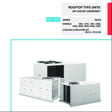
Hitecsa cy55
December 2021 0
Hitecsa Catalogo General 653fv
May 2023 0
Hitecsa Tarifa 2018 Es 240418 Link-min 5411z
April 2023 0More Documents from "leonel" 515v4o

Feldenkrais Moshe - Autoconciencia Por El Movimiento - El Libro Basico Del Metodo Feldenkrais 58n6y
September 2020 0
1b Puesta A Tierra De Las Instalaciones Electricas Industriales(1) 5yw6m
April 2020 201
Gaz- Norma Belga Nbn D51-003-1 1v1031
July 2021 0
6g3p1u
May 2022 0
Pdf Teorias Del Aprendizaje 5r4z4h
April 2020 197