Eigrp Ospf Redistribution Sim Configuration On Gns3 6861v
This document was ed by and they confirmed that they have the permission to share it. If you are author or own the copyright of this book, please report to us by using this report form. Report 2z6p3t
Overview 5o1f4z
& View Eigrp Ospf Redistribution Sim Configuration On Gns3 as PDF for free.
More details 6z3438
- Words: 5,554
- Pages: 33
EIGRP OSPF Redistribution Sim configuration On GNS3: EIGRP OSPF Redistribution CCNP Route Sim In following topology there are four router, R1, R2 and R3 are running in EIGRP AS 100. While R2’s s1/2 is running in OSPF area 24, R3’s f2/0 interface is running in OSPF area 34. In this Sim you need to redistribute OSPF into EIGRP so that they can communicate with each other. At the end of your configuration ping from R1 to Test IP 172.16.100.1 must be successful.
You can practice this simulation in GNS3 very easily; first you need to create above topology in GNS3 with following configurations. I have run EIGRP on R1, R2 and R3 and OSPF on R2 and R3 according to above diagram. In real Exam you don't have any concerned regarding routing protocols configuration you just need to redistribute OSPF and EIGPR
GNS3 Configuration: R1 Configuration:
R1(config)#int s1/0 R1 (config-if)#ip address 192.168.1.1 255.255.255.0 R1(config-if)#no shut R1(config)#exit R1(config)#router eigrp 100 R1(config)#network 192.168.1.0 0.0.0.255 R2 Configuration:
Router(config)#hostname R2 R2(config)#interface s1/0 R2(config-if)#ip address 192.168.1.2 255.255.255.0 R2(config-if)#interface s1/1 R2(config-if)#ip address 192.168.2.1 255.255.255.0 R2(config-if)#no sh R2(config-if)#interface s1/2 R2(config-if)#ip address 192.168.3.1 255.255.255.0 R2(config-if)#ip ospf 1 area 24 R2(config-if)#no shut R2(config)#router EIGRP 100 R2(config-router)#network 192.168.2.0 R2(config-router)#network 192.168.1.0 R3 Configuration: Router(config)#hostname R3 R3(config)#interface s1/0 R3(config-if)#ip address 192.168.2.2 255.255.255.0 R3(config-if)#interface f2/0 R3(config-if)#ip address 192.168.4.1 255.255.255.0 R3(config-if)#ip ospf 1 area 34 R3(config)#router EIGRP 100 R3(config-router)#network 192.168.2.0 R4 Configuration: Router(config)#hostname R4 R4(config)#interface s1/0 R4(config-if)#ip address 192.168.3.2 255.255.255.0 R4(config-if)#ip ospf 1 area 24 R4(config-if)#interface f2/0 R4(config-if)#ip address 192.168.4.2 255.255.255.0 R4(config-if)#ip ospf 1 area 34
After complete the above configuration you are at same stage where you need to configure this lab in exam. We have done so much as given in exam and from now on word you have to handle this complete the configuration.
Step for configuration in Exam:First we need 5 parameters of the s1/2 interface i.e. (Bandwidth, Delay, Reliability, Load, MTU) for this use command.
R2#config terminal R2(config)# router ospf 1 R2(config-router)# redistribute eigrp 100 metric-type 1 subnets R2(config-router)#exit R2(config-router)#router eigrp 100 R2(config-router)#redistribute ospf 1 metric 1544 2000 255 1 1500 For R3 we use the show interface fa2/0 to get these 5 parameters. R3#show interface f2/0
R3#config terminal R3(config)#router ospf 1 R3(config-router)#redistribute eigrp 100 metric-type 1 subnets R3(config)#exit R3(config-router)#router eigrp 100 R3(config-router)#redistribute ospf 1 metric 100000 100 255 1 1500
Verification & testing:
Show ip route on R1: You will see the all other routes if you done the correct configuration also ping from R1 to 172.16.100.1 should be successful.
IPv6 OSPF Virtual Link CCNP Route Sim Question Route.com is a small export company that has an existing enterprise network that is running IPv6 OSPFv3 for process 1. Currently OSPF is configured on all routers. However, R4′s loopback address (FEC0:44:4) cannot be seen in R1′s IPv6 routing table. You are tasked with identifying the cause of this fault and implementing the needed corrective actions that uses OSPF features and does no change the current area assignments. You will know that you have corrected the fault when R4′s loopback address (FEC0:44:4) can be seen in the routing table of R1.
Note: To gain the maximum number of points you must remove all incorrect or unneeded configuration statements related to this issue.
Step for Configuration: This lab is for testing your OSPF virtual-link concepts. And need to configure all routers with correct virtual-link commands. 1. you need to short out the wrong virtual-link configurations that you will find on R3 & R4 i.e. area 54 virtual-link 4.4.4.4 area 54 virtual-link 3.3.3.3 First remove these command and add the correct one. since i have simulate this lab in GNS3 for exam's practice that way first i have configured lab with wrong configuration as you will find in real exam in GSN3 configuration section and in Real exam section i correct all incorrect configurations and add with right configuration. GNS3 configuration:
Create this lab in GNS3 with following configuration, after these configurations you can start real lab configuration as you need to complete in exam. R1 Configuration: R1(config)#ipv6 unicast-routing R1(config)#interface Loopback1 R1(config-if)# ipv6 address FEC0:11::1/64 R1(config-if)#ipv6 ospf 1 area 0 R1(config-if)#EXIT R1(config-if)#interface FastEthernet1/0 R1(config-if)#ipv6 address FEC0:1::1/64 R1(config-if)#no shut R1(config-if)#ipv6 ospf 1 area 0 R1(config-if)#exit R1(config)#ipv6 router ospf 1 R1(config-rtr)#router-id 1.1.1.1 R2 Configuration: R2(config)#ipv6 unicast-routing R2(config)#int loopback 1 R2(config-if)#ipv6 address fec0:22::2/64 R2(config-if)#ipv6 ospf 1 area 0 R2(config-if)#EXIT R2(config-if)#interface FastEthernet1/0 R2(config-if)#ipv6 address FEC0:1::2/64 R2(config-if)#no shut R2(config-if)#ipv6 ospf 1 area 0 R2(config-if)#exit R2(config-if)#interface serial2/0 R2(config-if)#ipv6 address FEC0:2::1/64 R2(config-if)#no shut
R2(config-if)#ipv6 ospf 1 area 11 R2(config-if)#EXIT R2(config)#ipv6 router ospf 1 R2(config-rtr)#router-id 2.2.2.2 R3 Configuration: R3(config)#ipv6 unicast-routing R3(config)#int loopback 1 R3(config-if)#ipv6 address fec0:33::3/64 R3(config-if)#ipv6 ospf 1 area 11 R3(config-if)#EXIT R3(config-if)#interface FastEthernet1/0 R3(config-if)#ipv6 address FEC0:3::1/64 R3(config-if)#no shut R3(config-if)#ipv6 ospf 1 area 54 R3(config-if)#exit R3(config-if)#interface serial2/0 R3(config-if)#ipv6 address FEC0:2::2/64 R3(config-if)#no shut R3(config-if)#ipv6 ospf 1 area 11 R3(config-if)#EXIT R3(config)#ipv6 router ospf 1 R3(config-rtr)#router-id 3.3.3.3 Follow virtual-link configuration are wrong i have added these because in real exam you will find such wrong configuration and you need to removes these and need to configure R2 & R3 for virtuallink. Also in exam configuration i shall removes this area 54 virtual-link 4.4.4.4 command from R3 so that all routers can communicate with each other. R3(config-rtr)# area 54 virtual-link 4.4.4.4 R4 Configuration: R4(config)#ipv6 unicast-routing R4(config)#int loopback 1 R4(config-if)#ipv6 address fec0:44::4/64 R4(config-if)#ipv6 ospf 1 area 54 R4(config-if)#EXIT R4(config-if)#interface FastEthernet1/0 R4(config-if)#ipv6 address FEC0:3::2/64 R4(config-if)#no shut R4(config-if)#ipv6 ospf 1 area 54 R4(config-if)#exit R4(config)#ipv6 router ospf 1 R4(config-rtr)#router-id 4.4.4.4
Configuration required in Exam:
In this lab you need to configure virtual link for area 11 so that end to end communication can be possible. Step-1: Show Run on R1, R2 ans R3, and check the virtual links commands, if you found any of router please remove these first. Also note the router-ids and ospf process ID. In real exam IP addresses, OSPF process ids and area ids may be change, so you need to figure out the exact values by using show run. For example in R3 configuration you found area 54 virtual-link 4.4.4.4 which is unnecessary.
So please remove this. You need to make the virtual link on R2 & R3. We create virtual links when some OSPF area is not physically connected with backbone area (Area 0). The area through which you configure the virtual link is known as a transit area. Routers R2 and R3 are belonging to transit area that way need to add commands on these routers. R4#configure terminal R4(config)#ipv6 router ospf 1 R4(config-rtr)#no area 54 virtual-link 3.3.3.3 Step-2: Complete the virtual links configurations on R2 & R3. R3>enable R3#configure terminal R3(config)#ipv6 router ospf 1 R3(config-rtr)#no area 54 virtual-link 4.4.4.4 R3(config-rtr)#area 11 virtual-link 2.2.2.2 R2>enable R2#configure terminal R2(config)#ipv6 router ospf 1 R2(config-rtr)#area 11 virtual-link 3.3.3.3 R4>enableR4#show running-config You will see a wrongly configured virtual-link command. To get full mark we have to disable this command:
Verification: After configuration use command “Show IPv6 route” on R1, if you found the R4 route in routing table its mean you have done this lab successfully. And ping from R1 to R4 should be successful.
Important Tip: Please don’t forget to use IPV6 in every command e.g. Show IPV6 route, IPv6 router ospf 54 etc.
EIGRP Stub CCNP Route Sim Question
By increasing the first distant office, PNG manufactures has extended their business. They configured the remote office router (R3) from which they can reach all corporate subnets. In order to raise network stableness and lower the memory usage and broadband utilization to R3, RB manufactures makes use of route summarization together with the EIGRP Stub Routing feature. Another network engineer is responsible for the implementing of this solution. However, in the process of configuring EIGRP stub routing connectivity with the remote network devices off of R3 has been missing.
Presently PNG has configured EIGRP on all routers in the network R2, R3, and R4. Your duty is to find and solve the connectivity failure problem with the remote office router R3. You should then configure
route summarization only to the distant office router R3 to complete the task after the problem has been solved. The success of pings from R4 to the R3 LAN interface proves that the fault has been corrected and the R3 IP routing table only contains two 10.0.0.0 subnets. GNS3 Configuration: Create the above lab with following configurations in GNS3 and then practice this SIm with Real Exam configuration for your Route Exam. R3 Configuration: R3(config)# interface Loopback1 R3(config-if)#ip address 172.16.1.1 255.255.255.0 R3(config-if)#interface Serial1/0 R3(config-if)#ip address 10.2.3.3 255.255.255.0 R3(config-if)# No shut
R3(config-if)#end R3(config)#router eigrp 123 R3(config-rtr)#network 10.2.3.0 0.0.0.255 R3(config-rtr)#network 172.16.1.0 0.0.0.255 R3(config-rtr)#no auto-summary R3(config-rtr)#eigrp stub receive-only R4 Configuration: R4(config)# interface Serial1/0 R4(config-if)#ip address 10.2.3.4 255.255.255.0 R4(config-if)# No shut R4(config-if)#interface FastEthernet2/0 R4(config-if)#ip address 10.2.2.4 255.255.255.0 R4(config-if)# No shut R4(config-if)#end R4(config -rtr)#router eigrp 123 R4(config -rtr)#network 10.2.2.0 0.0.0.255 R4(config -rtr)#network 10.2.3.0 0.0.0.255 R4(config -rtr)#no auto-summary R2 Configuration: R2(config)#interface Loopback2 R2(config-if)#ip address 10.2.4.2 255.255.255.0 R2(config-if)# interface Loopback3 R2(config-if)#ip address 10.2.5.2 255.255.255.0 R2(config-if)#interface Loopback5 R2(config-if)#ip address 10.2.6.2 255.255.255.0 R2(config-if)#interface Loopback6 R2(config-if)#ip address 10.2.7.2 255.255.255.0 R2(config-if)#interface Loopback7 R2(config-if)#ip address 10.2.8.2 255.255.255.0 R2(config-if)#interface Loopback8 R2(config-if)#ip address 10.2.9.2 255.255.255.0 R2(config-if)#interface FastEthernet1/0 R2(config-if)#ip address 10.2.2.2 255.255.255.0 R2(config-if)# No shut R2(config-if)# end R2(config)# router eigrp 123 R2(config -rtr)#network 10.2.2.0 0.0.0.255 R2(config -rtr)#network 10.2.4.0 0.0.0.255 R2(config -rtr)#network 10.2.5.0 0.0.0.255 R2(config -rtr)#network 10.2.6.0 0.0.0.255 R2(config -rtr)#network 10.2.7.0 0.0.0.255
R2(config -rtr)#network 10.2.8.0 0.0.0.255 R2(config -rtr)#network 10.2.9.0 0.0.0.255 R2(config -rtr)#no auto-summary Real exam Configuration: Step-1: R4 & R3 are not communicating because of eigrp stub receive-only command in EIGRP Process 123. Due to this command router R3 is not sharing any of its routes with any other router in that EIGRP 123. To make the communication possible we need to replace this with eigrp stub command. R3#configure terminal R3(config)#router eigrp 123 R3(config-router)#no eigrp stub receive-only R3(config-router)#eigrp stubR3(config-router)#end Step-2: You need to configure route summarization on R4 so that R3 has only 2 subnets of 10.0.0.0 network. Use the show ip route command on R3 to view its routing table
For R3 only have 2 subnets we need Summarization at the R4's serial 1/0 interface which is connected with R3. To fulfill this requirement we configure R4 as follow, R4>enable R4#configure terminal R4(config)#interface s1/0 R4(config-if)#ip summary-address eigrp 123 10.2.0.0 255.255.0.0 Testing: Now show ip route command to the effect, the output is shown below:
In your real exam IPs might be different so you need configure R4 according to requirements.
GNS3 Labs | CCNP | CCNA Labs Blog is related to most famous network simulator i.e. "GNS3", here you can find different Labs, typologies and configuration regarding ICND, CCENT, CCNA, CCNP on GNS3.
Home ICND1 and ICND2 Labs | CCENT Sim CCNP Route (300-101 Exam) Labs CCNP Switch (300-115) Practice Labs CCNA 200-120 Labs
OSPF Stub Area Sim configuration on GNS3: Question A company has three routers Protland, Amsni and Lynaic. OSPF is configured on routers Amani and Lynaic. Amani’s S0/0 interface and Lynaic’s S0/1 interface are in Area 0. Lynaic’s Loopback0 interface is in Area 2. Details of configuration are as follow: Portland’s S1/0 interface in Area 1 Amani’s S1/0 interface in Area 1 Use the appropriate mask such that ONLY Portland’s S0/0 and Amnani’s S0/1 could be in Area 1. Area 1 should not receive any external or inter-area routes (except the default route).
GNS3 Configurations: First you need to create this topology in GNS3 as show above with following configurations. Portland Router: R1#config t R1 (config)# hostname Portland Portland (config)# enable secret cisco Portland (config)#interface Serial1/0 Portland (config-if)# ip address 192.168.4.5 255.255.255.252 Portland (config-if)#no shutdown Anami Router: R2#config t R2 (config)# hostname Anami Anami (config)# enable secret cisco Anami (config)#interface Serial1/0 Anami (config-if)# ip address 192.168.4.6 255.255.255.252 Anami (config-if)# no shutdown Anami (config)#interface Serial1/1 Anami (config-if)# ip address 192.168.72.6 255.255.255.252
Anami (config-if)#no shutdown Anami (config)#exit Anami (config)#router ospf 1 Anami (config-router)# network 192.168.4.4 0.0.0.3 area 1 Anami (config-router)# network 192.168.72.4 0.0.0.3 area 0
Lynaic Router: R3#config t R3 (config)# hostname Lynaic Lynaic (config)# enable secret cisco Lynaic (config)#interface loopback 1 Lynaic (config-if)# ip address 239.239.239.239 255.255.255.255 Lynaic (config-if)# ex Lynaic (config)#interface Serial1/0 Lynaic (config-if)# ip address 192.168.72.5 255.255.255.252 Lynaic (config-if)#no shutdown Lynaic (config)#exit Lynaic (config)#router ospf 1 Lynaic (config-router)# network 239.239.239.239 0.0.0.0 area 2 Lynaic (config-router)# network 192.168.72.4 0.0.0.3 area 0
Configuratio that you need in real exam: From above configuration you have notice that Portland router and Anami’s S1/0 interface is not running OSPF that way they are not able to communicate with other. In order to complete the configuration you need to run OSPF on these. For appropriate mask for 192.168.4.5\30 you need to find out the network ID for this subnet.
1
2
3
4
5
6
7
8
128
64
32
16
8
4
2
0
As we know that \30 is 6th bit of 4th octet that way from above table these subnets are divided into four number differences as follow.
Subet IDs for \30
Broadcast Address
0
3
4
7
8
11
12
15
And so on…….
……..
And from above we can see that 192.168.4.5 lie in 4-7 range therefore Subnet ID=192.168.4.4
Portland#configure terminal Portland(config)#router ospf 1 Portland(config-router)#network 192.168.4.4 0.0.0.3 area 1
“Area 1 should not receive any external or inter-area routes” configure area 1 as totally stubby area.
Portland(config-router)#area 1 stub Portland(config-router)#end Portland#copy running-config startup-config
Amani#configure terminal Amani(config)#router ospf 1 Amani(config-router)#network 192.168.4.4 0.0.0.3 area 1 Amani(config-router)#area 1 stub no-summary
Testing:
Ping from Lynaic to Portland should be successful and Lynaic have all route in its routing table. more CCNP Route Labs
Policy Based Routing CCNP Route Sim Question: Company Route.com has two links which can take it to the Internet. The company policy demands that you use web traffic to be forwarded only to Frame Relay link if available and other traffic can go through any links. No static or default routing is allowed.
Solution: I have created above lab in GNS3. BorderRouter and R1 are configured with EIGRP 11. I have used a cloud for generating HTTP Traffic. I connect the e3/0 interface with PC’s NIC using cloud and assigned the following IP.
And also add a manual route for 13.13.13.2 so that my PC can access internal R1 Router. For this go to Run\cmd (make sure you have rights) and use the following command. Route add 13.13.13.2 mask 255.255.255.255 14.14.14.1 –p
You can use “Route print” command to . In testing part I will show you how I generate HTTP traffic from using GNS3 cloud. GNS3 Configurations: To made communication between R1 and Borderrouter I use the EIGRP, in real exam lab you don’t have any concerned with routing protocol for this Sim you just need to create ACL and Route map in real exam. BorderRouter Configurations: R3#config t R3(config)#hostname Borderrouter Borderrouter(config)#interface e3/0 Borderrouter(config-if)# ip address 14.14.14.1 255.255.255.0 Borderrouter(config-if)#no shut Borderrouter(config)#interface s1/0 Borderrouter(config-if)# ip address 13.13.13.1 255.255.255.0 Borderrouter(config-if)#no shut
Borderrouter(config)#router eigrp 11 Borderrouter(config-router)#network 13.13.13.0 0.0.0.255 Borderrouter(config-router)#network 14.14.14.0 0.0.0.255 Borderrouter(config)#ip default-gateway 13.13.13.2 R1 Configurations: R1#config t R1(config)#interface s1/0 R1(config-if)# ip address 13.13.13.2 255.255.255.0 R1(config-if)#no shut R1(config)#router eigrp 11 R1(config-router)# network 13.13.13.0 0.0.0.255
Configurations that you needs in real Exam: First you need to create an access-list, which allows all HTTP traffic. BorderRouter#access-list 111 permit t any any eq www Secondly you need to create route-map to send the traffic through Frame-relay interface. BorderRouter(config)#route-map blockftp permit 10 BorderRouter(config-route-map)#match ip address 111 BorderRouter(config-route-map)#set ip next-hop 13.13.13.2 BorderRouter(config-route-map)#exit BorderRouter(config)#route-map blockftp permit 20 (Notice: blockftp is just name of route-map, u can use any name. The route-map blockftp permit 20 line allows other traffic than HTTP to be routed. Otherwise, other traffic will be dropped) 3) Apply the route-map on the interface to the server in the EIGRP Network: BorderRouter(config-route-map)#exit BorderRouter(config)#int e3/0 BorderRouter(config-if)#ip policy route-map blockftp BorderRouter(config-if)#exit
Testing and Verification: In Real Examthere is a “Host for Testing”, click on that. Then click on this “Generate HTTP traffic” button to generate some packets for HTTP traffic. Jump back to the BorderRouter and type the command “show route-map”. BorderRouter#show route-map You will see that 9 packets matches which that your configurations is correct. Testing in GNS3: To test your configurations in GNS3 you just type “http://13.13.13.2” in web browser. Result will be “cannot fine this page” but this will some http packets to frame-relay ISP.
Now type the command “show route-map”. BorderRouter#show route-map You will see packets matches.
//////Switch
VLAN Trunking Protocol (VTP) Switch Lab A company has added two new layer3 switches, one will act as distribution-layer switch while other will play the role of access-layer switch as shown in figure. You task is configure VTP (vlan trunking protocol) to distributing the VLAN information distribution-layer switch to the access-layer switch. Also configure interVLAN routing on the distribution layer switch to route traffic between the different VLANs that are configured on the access-layer switches; however, it is not compulsory for you to make the specific VLAN port assignments on the access-layer switches.
Please reference the following table for the VTP and VLAN information to be configured:
Tasks and requirements: VTP Domain name
Cisco
VLAN Ids
40
41
IP Addresses
172.16.71.40/24
172.16.132.41/24
These are your specific tasks: 1. Configure the above VTP information with the distribution layer switch (Dswitch) as the VTP server 2. Configure the VTP information with the access layer switch (Aswitch) as a VTP client 3. Configure VLANs on the Dswitch 4. Configure inter-VLAN routing on the Dswitch 5. Specific VLAN port assignments will be made as s are added to the access layer switches in the future. Note: All VLANs and VTP configurations are to completed in the global configuration of Switch. ---------------------------------------------------------------------------------------
Solution and Explanation: 1) Configure the VTP information Dswitch:
Open the console of distribution layer switch (Dswitch) and configure it with following configuration for above task: DSwitch>enable DSwitch#configure terminal Dswitch(config)#vtp mode server Dswitch(config)#vtp domain Cisco
2) Configure the VTP information with the access layer switch as a VTP client Access the console of Access layer switch Aswitch for performing the following configurations:
ASwitch>enable
Aswitch#configure terminal Aswitch(config)#vtp mode client Aswitch(config)#vtp domain Cisco 3) Configure VLANs on the distribution layer switch According to lab requirement create VLANs on a Dswitch by using the “vlan vlanID#” command in global configuration mode instead of “database vlan” command:
Dswitch(config)#vlan 40 Dswitch(config)#vlan 41 Assign the IP addresses for Vlans:
Dswitch(config)#interface vlan 40 Dswitch(if-config)#ip address 172.16.71.40 255.255.255.0 Dswitch(if-config)#no shutdown Dswitch(if-config)#interface vlan 41 Dswitch(if-config)#ip address 172.16.132.41 255.255.255.0 Dswitch(if-config)#no shutdown Dswitch(if-config)#exit 4) Configure inter-VLAN routing on the Dswitch
Dswitch(config)#ip routing Dswitch(config)#exit Dswitch#Write (save configurations) 5) Configure the VTP information with the access layer switch as a VTP client
Aswitch#configure terminal Aswitch(config)#vtp mode client Aswitch(config)#vtp domain cisco Aswitch(config)#exit Aswitch#copy run start
Interface VLAN Configuration on multilayer Switch (SIM) Lab Tasks: You need to configure multilayer Switch according to topology diagram and such that both hosts i.e. Host-A and Host-B are able to successfully ping the Internet server “Server_S1”.
You are not allowed to add/delete VLANs, changes VLAN port assignments or create trunk links. Also you can’t use a static or default routing. All routes must be learned via EIGRP 300 routing protocol. RouterC is correctly configured and no trunking has been configured on RouterC. Routed interfaces should use the lowest host on a subnet when possible. The following subnets are available to implement this solution: – 10.10.10.0/24 – 192.168.100.32/27 – 192.168.100.64/27 Hosts H1 and H2 are configured with the correct IP address and default gateway. The enable for Multi-Switch is Cisco. Routing must only be enabled for the specific subnets shown in the diagram.
Solution: Step to perform: -Find gateways of PCs with “ipconfig” command in Exam simulator, these gateways are use to configured as the virtual interface on multilayer switch for given VLANs and in our case we have the following:
Host1: IP Address: 192.168.100.36 Default gateway: 192.168.100.35 Host2: IP Address: 192.168.100.66 Default gateway: 192.168.100.65
-Note down the EIGRP AS number and VLANs information You can find it from topology diagram and it is EIGRP 300. VLAN 22 and 33 are created on multilayer switch and interfaces (connected to hosts) were configured as access ports so we don’t need to configure them in this sim, you also use the “show vlan” command for checking VLANs . -Configure the Virtual interfaces on switch According to SIM requirement we are not allow to use trunking therefore we will configure the MultiSwitch as a Layer 3 switch with SVIs for interVLAN routing and will configure these VLAN interfaces with gateways of PCs for respective VLANs. Multi-Switch# configure terminal Multi-Switch(config)# int f0/0 Multi-Switch(config-if)#no switchport (without using this command, the simulator does not let you assign IP address on f0/0 interface.) Multi-Switch(config-if)# ip address 10.10.10.2 255.255.255.0 (Router has IP address of 10.10.10.1 therefore we have to assign this interface with same IP-Range) Multi-Switch(config-if)# no shutdown Multi-Switch(config-if)# exit Multi-Switch(config)# int vlan 22 Multi-Switch(config-if)# ip address 192.168.100.35 255.255.255.224 Multi-Switch(config-if)# no shutdown Multi-Switch(config-if)# int vlan 33 Multi-Switch(config-if)# ip address 192.168.100.65 255.255.255.224 Multi-Switch(config-if)# no shutdown Multi-Switch(config-if)#exit
-Run the routing protocol on Multi layered switch
Multi-Switch(config)# ip routing (Notice: MLS will not work without this command) Multi-Switch(config)# router eigrp 300 Multi-Switch(config-router)# network 10.10.10.0 0.0.0.255 Multi-Switch(config-router)# network 192.168.100.32 0.0.0.31 Multi-Switch(config-router)# network 192.168.100.64 0.0.0.31
Pre-Radius Server configuration Buraqtech is a small cargo company that has an existing network consist of 2 switches, DSW1 and ASW1. The network diagram shows their layer 2 mapping. VLAN 10 is a new VLAN that will be used to provide the cargo personnel access to the server. For security reasons, it is necessary to restrict access to VLAN 20 in the following manner: – s connecting to ASW1’s port must be authenticate via a Radius server before they are given access to the network. The radius server address is 172.189.29.100 and Radius key is ciscoradius. – Authentication should be implemented as close to the host device possible. – Devices on VLAN 20 are restricted to in the address range of 172.120.10.0/24 and packets from devices in the address range of 172.120.10.0/24 should be ed on VLAN 20. – Packets from devices in any other address range should be dropped on VLAN 20. And this filtering should be configured as close to the server farm as possible. The Radius server and application servers will be installed at a future date. You have been tasked with implementing the above access control as a pre-condition to installing the servers. You must use the available IOS switch features.
Answer and Explanation:
1) Configure authenticate via a Radius server on ASW1 ASW1(config)#aaa new-model
Set the server address and for radius server: ASW1(config)#radius-server host 172.189.29.100 key ciscoradius ASW1(config)#aaa authentication dot1x default group radius Enable 802.1x on the switch: ASW1(config)#dot1x system-auth-control Configure Fa0/1 to use 802.1x: ASW1(config)#interface fastEthernet 0/1 ASW1(config-if)#switchport mode access ASW1(config-if)#dot1x port-control auto Notice that the word “auto” will force connected PC to authenticate through the 802.1x exchange. ASW1(config-if)#end ASW1#write Packets from devices in the address range of 172.120.10.0/24 should be ed on VLAN 20. Define an access-list: DSW1(config)#ip access-list standard 10 DSW1(config-std-nacl)#permit 172.120.10.0 0.0.0.255 DSW1(config-std-nacl)#exit Define an access-map which uses the access-list above: DSW1(config)#vlan access-map MYMAPIP 10 DSW1(config-access-map)#match ip address 10 DSW1(config-access-map)#action forward DSW1(config-access-map)#exit Packets from devices in any other address range should be dropped on VLAN 20. DSW1(config)#vlan access-map MYMAPIP 20 DSW1(config-access-map)#action drop DSW1(config-access-map)#exit Apply a vlan-map into a vlan close to the server farm as possible: DSW1(config)#vlan filter MYMAPIP vlan-list 20
PortFast spanning tree configuration: Lab Tasks: Suppose your company has installed a new Switch in your existing network to connect 24 additional s. You need to configure the switch correctly so that it will not disturb your existing configuration of your network. You also have to ensure that the switch does not participate in VTP (VLAN trunking protocols) but forwards VTP updates and ments that are received on trunk ports. Because of errors that have been experienced on office computers, all nontrunking interfaces (all Fast Ethernet ports) should transition immediately to the forwarding state of Spanning tree.
Ensure the following configurations on Switch:
Configure all port of Switch as access-ports and assign the VLAN 20 to Fast Ethernet ports 1/12 to 1/24 in global configuration mode.
Switch does not participate in VTP but forwards VTP ments received on trunk ports.
Ensure all access interfaces (1-24) of switch transition immediately to the forwarding state of Spanning-Tree.
Ensure all FastEthernet interfaces are in a permanent non-trunking mode. Solution for STP Switch Lab:
Configure all port of Switch as access-ports or non-trunking ports Switch>enable Switch#configure terminal Switch(config)#interface range fa1/1 – 24 Switch(config-if-range)#switchport mode access
Assign the VLAN 20 to Fast Ethernet ports 1/12 to 1/24 in global configuration mode.
By default, all ports on the switch are in VLAN 1. To change the VLAN associated with a port, you need to go to each interface (or a range of interfaces) and tell it which VLAN to be a part of. Switch(config-if-range)#interface range fa1/12 – 24
Switch(config-if-range)#switchport access vlan 20 Switch(config-if-range)#exit Ensure all access interfaces (1-24) of switch transition immediately to the forwarding state of Spanning-Tree. Switch(config)#interface range fa1/1 – 24 Switch(config-if-range)#spanning-tree portfast
Switch does not participate in VTP but forwards VTP ments received on trunk ports.
Switch(config)#vtp mode transparent Switch(config)#exit
And finally you can save the configuration with one of following command. Switch#copy running-config startup-config OR Switch#Write
Link Aggregation Control Protocol Configuration: Suppose you have just added a new switch (SwitchB) to the existing network as shown in the topology.
RouterA is currently configured correctly for providing the routing function for devices on SwitchA and SwitchB. You need to be modified SwitchA to the addition of SwitchB. You have been tasked with competing the needed configuring of SwitchA and SwitchB. SwitchA and SwitchB use Cisco as the enable . Configuration Requirements for SwitchA The VTP and STP configuration modes on SwitchA is correct and should not be modified. You need to configure SwitchA as root switch for vlans 11, 12, 13, 21, 22 and 23. All other vlans should be left are their default values. Configuration Requirements for SwitchB You need to configure the VLANs according to following information: VLAN# VLAN NAME VLAN Ports 21 HR Fa1/9 and fa1/10 22 Finance Fa1/5 and fa1/6 23 Marketing Fa1/15 and fa1/14 – Access ports that assigned to VLANs should transition immediately to forwarding state upon detecting the connection of a device.
– SwitchB VTP mode needs to be the same as SwitchA. – SwitchB must operate in the same spanning tree mode as SwitchA. And no routing is required on this Switch –SVI vlan 1 is to be configured with IP address 192.168.1.11/24. Inter-switch Connectivity Configuration Requirements: - For operational and security reasons trunking should be unconditional and Vlans 1, 21, 22 and 23 should tagged when traversing the trunk link. – The two trunks between SwitchA and SwitchB need to be configured in a mode that allows for the maximum use of their bandwidth for all vlans. This mode should be done with a non-proprietary protocol, with SwitchA controlling activation. – Propagation of unnecessary broadcasts should be limited using manual pruning on this trunk link.
Answer and Explanation:
Some useful commands that may help you to find out the necessary information on SwitchA are as following: (Cisco basic router Commands) show vtp status (you can get the information about VTP status on SwitchA i.e. SwitchA is in transparent mode) show spanning-tree (rapid-pvst mode on SwitchA) show vlan (check the native vlan and the existence of vlan100) show etherchannel 1 port-channel and show ip int brief (check if Port-channel 1 has been created and make sure it is up) show run (for complete configuration of Switch)
Configure the SwitchA as root switch for vlans 11, 12, 13, 21, 22 and 23 and need to have the same configuration as the SwitchB for successful configuration. SwitchA>enable SwitchA #configure terminal SwitchA (config)#spanning-tree vlan 11,12,13,21,22,23 root primary SwitchA (config)#vlan 21 SwitchA (config-vlan)#name HR SwitchA (config-vlan)#exit SwitchA (config)#vlan 22 SwitchA (config-vlan)#name Finance SwitchA (config-vlan)#exit SwitchA (config)#vlan 23 SwitchA (config-vlan)#name Marketing SwitchA (config-vlan)#exit SwitchA (config)#interface range Fa1/3 – 4
SwitchA (config-if-range)#switchport mode trunk SwitchA (config-if-range)#switchport trunk native vlan 100 SwitchA (config-if-range)#switchport trunk allowed vlan 1,21,23 SwitchA (config-if-range)#channel-group 1 mode active SwitchA (config-if-range)#channel-protocol la SwitchA (config-if-range)#no shutdown SwitchA (config-if-range)#end ——————————————————————————————– Configuration VLANs according to given table: SWITCHB#configure terminal SWITCHB(config)#vlan 21 SWITCHB(config-vlan)#name HR SWITCHB(config-vlan)#exit SWITCHB(config)#vlan 22 SWITCHB(config-vlan)#name Finance SWITCHB(config-vlan)#exit SWITCHB(config)#vlan 23 SWITCHB(config-vlan)#name Marketing SWITCHB(config-vlan)#exit SWITCHB(config)#vlan 100 SWITCHB(config-vlan)#name TrunkNativeVlan SWITCHB(config-vlan)#exit SWITCHB(config)#interface range Fa1/9 – 10 SWITCHB(config-if-range)#switchport mode access SWITCHB(config-if-range)#switchport access vlan 21 SWITCHB(config-if-range)#spanning-tree portfast (Access ports that assigned to
VLANs should transition immediately to forwarding state upon detecting the connection of a device.) SWITCHB(config-if-range)#no shutdown SWITCHB(config-if-range)#exit SWITCHB(config)#interface range Fa1/5 – 6 SWITCHB(config-if-range)#switchport mode access SWITCHB(config-if-range)#switchport access vlan 22 SWITCHB(config-if-range)#spanning-tree portfast SWITCHB(config-if-range)#no shutdown SWITCHB(config-if-range)#exit SWITCHB(config)#interface range Fa1/14 – 15 SWITCHB(config-if-range)#switchport mode access SWITCHB(config-if-range)#switchport access vlan 23 SWITCHB(config-if-range)#spanning-tree portfast SWITCHB(config-if-range)#no shutdown SWITCHB(config-if-range)#exit
SwitchB VTP mode needs to be the same as SwitchA: SWITCHB(config)#vtp mode transparent SWITCHB(config)#spanning-tree mode rapid-pvst Configure VLAN-1 with IP address 192.168.1.1: SWITCHB(config)#interface vlan 1 SWITCHB(config-if)#ip address 192.168.1.11 255.255.255.0 SWITCHB(config-if)#no shutdown SWITCHB(config-if)#exit
Vlans 1, 21, 22 and 23 should tagged when traversing the trunk link: SWITCHB(config)#interface range Fa1/3 – 4 SWITCHB(config-if-range)#switchport trunk encapsulation dot1q SWITCHB(config-if-range)#switchport mode trunk SWITCHB(config-if-range)#switchport trunk native vlan 100 SWITCHB(config-if-range)#switchport trunk allowed vlan 1,21-23
Maximum use of bandwidth for all vlans with SwitchA controlling activation: SWITCHB(config-if-range)#channel-group 1 mode ive //mode ive because “SwitchA controlling activation” SWITCHB(config-if-range)#channel-protocol la SWITCHB(config-if-range)#no shutdown SWITCHB(config-if-range)#end
Question:
A company has an existing network comprised of 5 switches; CoreSwitch DSW1 DSW2 Switch1 Switch2 This switch network has pre-VLAN spanning tree mapping. You has the following tasks to complete this Lab: – CoreSwitch should be the root bridge for VLAN 20, but currently DSW1 is the root bridge for VLAN 20. – Traffic for VLAN 30 should be forwarding over the gig 1/0/6 trunk port between DSW1 and DSW2. However VLAN 30 is currently using gig 1/0/5. – Traffic for VLAN 40 should be forwarding over the gig 1/0/5 trunk port between DSW1 and DSW2. However VLAN 40 is currently using gig 1/0/6.
You task is complicated by the fact that you only have full access to DSW1, with the enable cisco. You are allowed and provided only limited show commands access is provided on CoreSwitch, and DSW2 using the enable 2 level with a of Cisco. You are not allowed to made configuration changes on these Switches. Also you don’t have access to ASW1 or ASW2. So you are only limited to make configuration on DSW1.
Required Configurations and Explanation:
1. “CoreSwitch should be the root bridge for VLAN 20. DSW1 is currently the root bridge for VLAN 20″ our task to make CoreSwitch the root bridge for VLAN 20. For making the CoreSwitch as a root bridge we need to assign the lowest priority value for VLAN 20 on CoreSwitch, but we are not allowed to make changes on this Switch we have only access to DSW1 therefore we can increase the priority of DSW1 so that it become higher than CoreSwitch. For this use the
“show spanning-tree” on CoreSwitch and on DSW1 for checking the priority of both switches for
VLAN 20. Currently DSW1 is the root bridge for VLAN 20 (notice the line “This bridge is the root” on below figure). DSW1>enable DSW1#show spanning-tree
To make the CoreSwitch the root bridge we need to increase the DSW1′s priority value, the best value should be you can use another value but make sure it is higher than the CoreSwitch priority value by checking if the CoreSwitch becomes the root bridge or not; and that value must be in increments of 4096. DSW1#configure terminal DSW1(config)#spanning-tree vlan 20 priority 61440
2.“Traffic for VLAN 30 should be forwarding over the gig 1/0/6 trunk port between DSW1 and DSW2. VLAN 30 is currently using gig 1/0/5″ and gig 1/0/6 is in blocking state, you can find these information by using command “show port base on Bridge-ID
Port-Cost
Interface-ID
spanning-tree”. We know that spaning tree protocol make the forwarding
Since both ports have same bridge-ID and both interfaces are fastethernet therefore they will have the same port-cost. When the both ports have same port-cost and bridge-ID then the port with the lower interface will be in forwarding state while other will be in blocking state. Same happen in this case that both switches DSW1 and DSW2 have same bridge-ID and Cost therefore gig 1/0/5 is forwarding port for VLAN 30. Now you can make the gig 1/0/6 as forwarding port by lowering the Priority Number of the port gig 1/0/6 you can see the currently priority numbers of ports by show
tree”
Notice that we only need to change this value for VLAN 30, not for all VLANs. DSW1(config)#interface g1/0/6 DSW1(config-if)#spanning-tree vlan 30 port-priority 64
“show spanning-
DSW1(config-if)#exit
“3. Traffic for VLAN 40 should be forwarding over the gig 1/0/5 trunk port between DSW1 and DSW2. However VLAN 40 is currently using gig 1/0/6″ and our task is to make the forwarding of VLAN 40 through gig 1/0/5. It is a similar job, but we are not allowed to make any configurations on DSW2, and in this case we can’t change the port-priority for VLAN 40. There is another solution for this you can change the cost (set the lower value) on an interface of DSW1 then only DSW1 will learn the change. By default, the cost of a 100Mbps link is 19 but we can change this value to make sure that VLAN 40 will use interface Gig1/0/5. DSW1(config)#interface g1/0/5 DSW1(config-if)#spanning-tree vlan 40 cost 1 DSW1(config-if)#exit You should re-check to see if everything was configured correctly: DSW1#show spanning-tree DSW1#copy running-config startup-config
////GNS3 with Mobaxterm
Related Documents c2h70

Eigrp Ospf Redistribution Sim Configuration On Gns3 6861v
September 2021 0
Redistribution Between Eigrp And Ospf Cisco Router Configuration 554s3w
November 2019 21
Eigrp Vs Ospf 5k54o
April 2020 14
Configuration Ospf De Base.pdf 6h6830
July 2021 0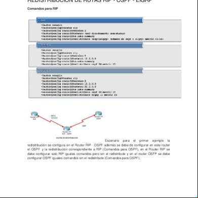
Redistribucion De Rutas Rip Eigrp Ospf 6i2u5s
April 2020 21
Www Getnetworking Net Route Map Redistribution Into Eigrp Wi 6x471s
October 2022 0More Documents from "Anonymous cs4BLczE" 5r48j

New 21 Hiko Questions _ Waleed Verifications 6zv5e
September 2022 0
Example Presentation Topics 5p6621
October 2019 91
Tshoot Ping Plan Sam 6v6x4f
November 2019 298
Cus10.composite Screens In T24-r10.01 5w41g
June 2020 3
Eigrp Ospf Redistribution Sim Configuration On Gns3 6861v
September 2021 0