Dentium-practical Course Training - Sylabus 441f21
This document was ed by and they confirmed that they have the permission to share it. If you are author or own the copyright of this book, please report to us by using this report form. Report 2z6p3t
Overview 5o1f4z
& View Dentium-practical Course Training - Sylabus as PDF for free.
More details 6z3438
- Words: 11,206
- Pages: 813
IMPLANT INTENSIVE PRACTICAL COURSE
CONTENTS 01. What is Implant? 02. Implant Types 03. Dentium Implants 04. Anatomy 05. Patient Evaluation
06. Implant Selection 06. Treatment Plan 07. Case Presentation
What is Implant? An Implant is a medical device manufactured to replace a missing biological structure, a damaged biological structure, or enhance an existing biological structure. A dental implant is a "root" device, usually made of titanium, used in dentistry to restorations that resemble a tooth or group of teeth to replace missing teeth.
Dental implants can be used to a number of dental prostheses, including crowns, implant-ed bridges or dentures. They can also be used as anchorage for orthodontic tooth movement.
History of Dental Implant Ancient - Egypt, Middle East, Honduras, Maya civilization - tooth shaped shell or Ivory 1728 - Pierre Fauchard : Metal Screw post Implant 1809 - Maggilio : Gold Implant Modern Implantology
1941 - Dahl : Subperiosteal Implant 1947 - Formiggini : Tantalum twisted Spiral Endosteal Implant 1963 - Linkow : Tantalum Vent - Plant, 1967 - Linkow blade 1965 - Branemark Implant System : History: As a Vital microscopic technique to study healing events and Microcirulation in bones and bone marrow using rabbits’ fibula, titanium chambers containing an optical System for transillumination was implanted for the study. The optical chambers used could not be removed because the titanium framework became completely incorporated in bone. Thus, the concept of OSSEOINTEGRATION emerged. The first Branemark implant was placed in human jaw in 1965.
Osseointegration OSSEOINTEGRATION is defined as a direct structural and functional connection between ordered, living bone and the surface of a load-carrying implant. (Branemark 1985) OSSEOINTEGRATION is a process hereby clinically asymptomatic rigid fixation of alloplastic materials is achieved, and maintained, in bone during functional load. (Zarb & Albrektson 1991) 5
Implant Types Classifications By Connection: - External vs Internal By Surgical
position:
- Submerged vs Non-Submerged By Surface Characteristics: - Smooth vs Rough Surface vs Chemical Modification
By Body
Design:
- One body implant (Solid) vs Two body implant (hollow) - Parallel body vs Tapered Body
Others - Zirconia Implants
Connection External - ABUTMENT CONNECTED EXTERNALLY - SCREW LOOSENING - MULTI IMPLANT CASE
Internal - ABUTMENT CONNECTED INTERNALLY - PREVENT SCREW LOOSENING - MORE LOADING STRENGTH
7
Surgical position
GBR? STABILITY? CONVENIENT? POSITION? COSMETIC?
Submerged
Non-Submerged
ONE BODY VS TWO BODY ONE BODY
TWO BODY
VS
Surface Characteristic Smooth Surface - Machined surface Rough surface - Sand blasted with Large grit and Acid etching (SLA), - resorbable blast media (RBM), - Etching, - Sintering Chemical modification - HA Coating, - Oxidised
Implant Surfaces
Machined surface eg. Branemark Implant
Oxidized Surface eg Nobel Direct
Sand blasted with Large grit and Acid etching eg. Dentium, Straumann
Anodizing eg. Nobel Biocare Ti-Unite
HA coating eg. Steri-oss
Sintering eg. Endopore
SLA - the standard of rough surface
growth factor BMP collagen peptide coating
DENTIUM - SUPERLINE
SUPERLINE
Easy Esthetics Beautiful Teeth. Superior esthetic biomaterials and individualized applications.
Soft Tissue Integration Beautiful Gingiva. Surfaces, designs, and procedures for maintaining and regaining natural soft tissue.
Immediate Function No healing time required prior to functioning. Surfaces, designs, and procedures for maintaining implant stability.
Focal
The effects of Implant surface topography on the behavior of cells
Surgically created wound during implant installation
Enhancing adsorption of circulating growth factors & cytokines and promoting cell migration
Immediately condition the surface. Expose material surface to wound fluid & molecules; rich in fibrin, fibronectin, hyaluronic acid
DENTIUM - SIMPLELINE
Increase overall stability 1.Implant surface texture 2.Implant surface treatment 3.Implant fixture design
Initial stability
Initial stability
almost like a cylindrical, press-fit implant
Design - tapered implant; SuperLine Higher initial stabilization - early loading
Reduced bone heating - easy drilling sequence - easy installation
FX3610SW
FX4010SW
FX4510SW
FX5010SW
FX6010SW
FX7010SW
Fixture Design Features Superline Taper portion
Double threads
Bone expansion & Initial stability
Smooth
Parallel portion Distribute stress evenly
and tight fixation
S.L.A. Surface S.L.A. Successful early loading
F 23
Taper portion
Biological Thread
Easy Installation
Rich bone housing design
Insertion Torque Curve - Superline
Superline, attractive implant system for hard & soft tissue integration
Taper neck design give a strong primary stability
Attractive Implant System for clinician • • • • • • • •
- Minimize GBR procedure - No bone resorption due to even stress distribution - Easy and well achievement of initial stability - Faster Osseointegration - Easy prosthetic procedures - Reasonable Price - Company & Service
Our patients want ! • Short treatment time Few injection Good esthetics Short term provisional Reasonable Fee
Marginal Bone Stability
It is a key factor for a way to esthetic outcome
Bone response Marginal bone remodeling Stable marginal bone
1. conventional loading – 0.35mm bone loss after 1 year 2. early loading – 0.55mm bone loss after 1 year and after that the bone level was maintained
Conical Seal Design 11°
*Self guiding – allows simple assembling *Tight relation – eliminates micro-motion, less screw loosening *Geometric locking – creates strength, rigid connection *Conus surface – distributes load evenly
f2
f1 F
Platform switching - Cell: withdrawal tendency from connecting point (t) between fixture and abutment - Biological width concept - Horizontal offset: most important factor - Inflammatory cell infiltration: away from the bone
Effect of platform switching (Lazzara 2006)
Typical bone loss (saucerization)
Platform switching (>0.4mm)
Platform switching: A new concept in implant dentistry for controlling postoperative crestal bone level (RJ Lazzara & SS Porter IJPRD 2006)
Once exposed in the oral cavity following the implant installation, the coronal bones are remodeled.
ANATOMY
ANATOMY
A inferior alveolar nerve B dentogingival nerve C mental nerve D incisor nerve ( anterior inferior alveolar nerve )
A mental nerve B dentogingival nerve C incisor nerve ( anterior inferior alveolar nerve )
ANATOMY
A B C D
posterior superior alveolar nerve anterior superior alveolar nerve infraorbital nerve lateral nasal nerve
A B C D E F
posterior superior alveolar nerve middle superior alveolar nerve anterior superior alveolar nerve dental plexus canine plexus infraorbital nerve
Systematic Evaluation Absolute contraindications Relative contraindications Others
Absolute Contraindications Systemic diseases Cancer and AIDS Cardiac diseases Deficient haemostatic and blood dyscrasias -Hemophilia, Thrombocytopenia, Acute leukemia, Agranulocytosis. Anti-coagulant medication -Aspirin, Wafarin Psychological disease Uncontrolled acute infection Drugs used to treat or prevent postmenopausal and steroid-induced osteoporosis. Pregnancy
Relative Contraindications Diabetes Jaw irradiation Chemotherapy Smoking
Others Osteoporosis Age
Dental Evaluation General Considerations Dental Examination for Implant Therapy
General Considerations Radiographic examinations -Panorama, Full mouth series Since they serve as the reservoir of bacterial colonization, the infected periodontal site and caries must be addressed prior to surgery Good oral hygiene is critical in implant treatment; as for the cooperation of the patient
Dental Examination for Implant Surgery Arch shapes and Sizes -Required for deciding the number and positions of implant especially among edentulous patients. Maximum intercuspation, Centric relation and Occlusal interferences -In case of partially edentulous patients, the existing occlusion can be maintained or must be considered prior to surgery in case improvement is necessary Anterior guide -In the absence of an anterior guide, implants in the posterior may receive excessive lateral force. -Excessive anterior guide may result in overload on the implants in the anterior.
General wear facets and Other signs of parafunctional habits -Implant prosthesis should be protected from other hazardous forces.
Interarch relationship -Posterior Implants require about 7mm of space, and the anterior, 8~10 mm. In the case of implant-retained removable prosthesis, at least 12 mm space is required for the bar clip. Adjacent teeth -Single implants need at least 7 mm of space from the CEJ of the mesial tooth to that of the distal tooth. -The mesial inclination of the distal tooth must be addressed either prosthetically or orthodontically. -Adjacent teeth should not be exposed to infection sources; otherwise, periodontal or endodontic treatment must be performed first. Aesthetic evaluation -The analysis of the smile line is essential in an implant treatment in the upper anterior. Diagnostic casts & Diagnostic wax-up
Clinical Evaluation Evaluation of tissue health Attached gingiva Evaluation of the edentulous space Palpation
Evaluation of tissue Health Edentulous gingival tissue should neither be inflamed nor afflicted with pathogens.
Attached gingiva Edentulous gingival tissue should neither be inflamed nor afflicted with pathogens. The volume of the attached gingiva should be measured at MGJ. Although the sufficient volume of the attached gingiva is not necessarily required, it is important for the long-term maintenance of prosthesis.
Evaluation of the edentulous space The buccolingual ridge should at least be 6mm wide. The mesiodistal ridge should be at least 7 mm wide. Knife-edge ridge -Bone grafting and FGG may be necessary. -The ridge split technique can be applied.
Palpation Palpate a ridge to check the existence of concavity or exostosis. In case of the lower posterior, check the concavity in the lingual side, and in the upper anterior, that in the labial side.
Radiographic Diagnosis
Periapical Radiographs Panoramic Radiographs Lateral Cephalogram Transparent sheets for implant selectio C.T & Cone Beam
Periapical Radiographs Distortion is minimised using the parallel technique. The bone level of adjacent teeth must be visible. The use of the grid enables direct length measurement. Its main application is recall check.
Panoramic Radiographs Bone quality, quantity and anatomical limitation may be evaluated. Distortion often occurs and varies by image. The application of radiographic template using radiopaque markers is recommended.
Lateral Cephalogram During implant installation, the surgeon can check the thickness of the cortical bones as well as the volume of the buccolingual bones in the lower anterior or symphysis grafting is required.
Transparent sheets for Implant Selection Select an implant using the transparent sheet provided by Choose the implant size and length with appropriate proportions by calculating the augmentation ratio.
C.T & Cone Beam Best accurate radiology for implant installation.
Choice of implant length, diameter and position • • •
Implant length Implant diameter Implant position
• ★
Implant length
Determine the implant length based on bone availability and calculate the available bone height. ★ For implants in the lower posterior, perform osteotomy with at least 2mm space away from nerves. ★ Choosing a relatively long implant is unnecessary given sufficient bone height. A longer implant does not provide additional , instead making surgical cooling trickier.
•
Implant diameter
★
Measure the buccolingual ridge dimension. Set the diameter with more than 1 mm of buccal and lingual bone remain. If the ridge is narrow, expand with osteotome or perform GBR and ridge splitting. ★ For the mesiodistal area, maintain 3mm distance between implants and set the diameter such that there is at least 1.5mm distance between the implant and natural teeth. ★ Indications for small diameter (∅ 3.4) Implant -Reduced inter-root space: The inter-root distance is less than 7mm. -Thin alveolar crest -Reduced mesio-distal prosthetic space
★Indications
for large diameter (∅ 4.3, 4.8) Implant
-Insufficient bone quality
• ★
Implant diameter
In case of posterior teeth, let the implant angulation tend toward the center of the occlusal surface and face the functional cusp of antagonist teeth. ★ In case of anterior teeth and cemented prosthesis, place the implant along the axis toward the incisal edge. ★ If insertion into the ideal position is difficult, use a phased approach through bone grafting prior to insertion. ★ Avoid damaging the adjacent teeth of the implant. Maintain at least 1.5mm space between the implant and adjacent teeth (PDL space of adjacent teeth + 1mm). ★ In case of multiple implants, maintain at least 3mm of space among implants and place them parallel to each other if possible.
TreatmentPlan ning
Reference : Australian Dental Journal Volume 53, Suppl 1, June 2008
General considerations Treatment planning must include the prosthesis design, grafting procedures, temporization, and number and positions of implants. A detailed plan should be prepared for surgery and prosthesis. If more complicated procedures such as bone grafting and multiple implant installations are involved, treatment documents, order, and treatment schedule and duration as well as any and all changes should be documented. Initial disease control should precede treatment planning. ※ Initial disease control phase - Treatment of periodontal & endodontic problems - Caries control - Oral hygiene instructions - Extraction of hopeless teeth - Transitional restoration Prior to treatment planning, it is important to motivate the patients and evaluate their estimated long-term cooperation based on their reaction to early Tx.
Selecting a Prosthetic Design General principles
• Prosthesis types - Fixed - Removable restoration • Prosthetic options depend on the conditions of partial and fully edentulous patients. • Diagnostic casts and wax-up are necessary for purposes of prosthetic design selection and explanation to the patients.
General decision criteria • • • • •
Comfort level of the dentist & technician Patient access to maintenance Feasibility of repairs Research-based design when available Patient expectations
Other general considerations a. Connection vs. No connection to natural teeth • Although avoiding the connection between natural teeth and implants is recommended, it is not a contraindication in some carefully chosen cases. • For teeth with insufficient periodontal , however, avoid such connection. • If connection is necessary, perform final cementation on rigid fixed prosthesis to prevent the intrusion of natural teeth.
b. Cantilever vs. No cantilever • If possible, avoid cantilever restoration (may cause overload on the implants). • Cantilever should be limited to a short span. • For edentulous cases and fixed prosthesis, treatment can be made with the distal cantilever whose length is up to 1.5 times as large as distance between the center of the foremost implant and that of the rearmost implant. ※By installing implants inclined distally in the most posterior area, the amount of cantilever can be reduced. If arranging the implants in the appropriate positions is difficult, consider the removable prosthesis as an option.
c. Inter-and Intra-arch space • At the stage of treatment planning, consider in advance the inter- and intra-arch space and height and width of the prosthesis to be inserted. • Before selecting the prosthesis, check the heights of all prosthetic components. Ex) Removable prosthesis -Height of the implant abutment -Height of attachment and housing • Forming the appropriate occlusal plane requires reducing the height of antagonist teeth. • Secure the appropriate inter-proximal distance for prosthetic and orthodontic purposes. • Excessive inter-arch space may result in poor crown/implant ratio.
d. One-stage vs. Two-stage Implant • Whether to perform one-stage or two-stage implant installation depends on the condition of the patient as determined by the surgeon. • Advantages of One stage surgery - Sufficient soft tissue healing time. - Stabilization of JE & Sulcus depth. - No disruption of mature peri-Implant tissue during prosthetic work. • Disadvantages of One stage surgery. - Infection during bone healing phase. - Previous enough bone grafting (Staged approaches). - No chance of healing time after surgical trauma.
• Two-stage Implant : SUPERLINE - Designed for two-stage implant installation, SUPERLINE widens the abutment for an implant with narrow diameter for enhanced emergence profile. In other words, the emergence profile in the existing SUPERLINE is not affected by the implant diameter. - Indication: SUPERLINE can be used when the bone width is not ideal and in case the gingiva is too narrow or thick. • Standard Implant surgery protocol : Two stage surgery. - Conservative & Safe. - Less bone loss due to enough healing time before 2nd stage surgery. • Guideline for one or two staged approaches. - Good patient cooperation. - No infection source. - No smoking. - More delicate drilling. - Enough antibiotic & antiseptic coverage: 1week antibiotics, weeks chlorhexidine, after 2weeks, tooth brushing one stage approaches area.
2 surgical
Treatment Planning in the esthetic zone General considerations • Aesthetic evaluation must be performed, and possible limitations, identified. • During Tx planning, a plan for a temporary prosthesis that ensures the patient’s comfort and satisfaction must be prepared. • In case of insufficient soft tissue and/or hard tissue, perform grafting to install implants in more ideal positions and fabricate aesthetic prostheses.
Diagnosis • First, examine the smile line of the patient. Photographs of the oral cavity can help visualize the basic points more specifically. • Check whether the incisal edges are natural along the inferior line. • Evaluate the amount of gingiva exposed. Determine the causes of gummy smile. - Malpositioned maxilla → Orthodontic evaluation is necessary. - Short lip (Lip incompetence at rest but normal maxilla) - Hyperactive upper lip (Normal lip coverage at rest, but uncovering during smile) - Excess soft tissue • If the smile line is unaesthetic, various Tx options should be offered to patients. • In the aesthetic zone, installing implants in more accurate positions is critical. Otherwise, hard and/or soft tissue grafting should be performed as supplementary treatment. • Once installed, the implant restricts other treatments. In particular, some orthodontic tooth movements require the extraction of implants.
Treatment Planning • The emergence profile of the prosthesis should be considered carefully. • To secure a natural emergence profile, implants should be inserted more deeply in the posterior area. • A surgical stent is a prerequisite to ideal implant positioning in the aesthetic zone. • Although an inaccurately inserted implant toward the labiolingual side can be corrected with an angled abutment, the correctable angle is limited. • The future resorption of bone and soft tissue must be considered. Therefore, grafting should be performed slightly excessively.
Biotypes & Difficulties of Restoration a. Thick & Flat biotype • • • • • •
Most common Teeth are square with relatively parallel roots point is wide Underlying bone is thick and resistant Papilla are flat and wide Generally associated with favorable surgical and restorative outcomes
b.Thin & Scalloped biotype • Comprises 20% of the population • Teeth have conical roots and triangular crowns. • Underlying bone is thin, and dehiscences are frequent. • Papilla extend incisally, becoming thin and delicate. • When a tooth is missing, severe hard and soft tissue loss has occurred. • Surgical reconstructions are difficult, particularly when attempting to regenerate papilla. • A favorable outcome is more difficult to achieve, and expectations should be tempered.
Number of missing teeth a. One missing tooth • Teeth adjacent to the edentulous space have a significant effect on the maintenance of tissue height. • The papilla is well maintained given good bone for adjacent teeth.
b. Two or more missing teeth • Severe loss of hard and soft tissue requires advanced surgical procedures. • Inter-implant bone must be well maintained to the proximal tissues. • Secure at least 3mm space between implants. • Insufficient space between implants results in the loss of inter-proximal bones due to the early remodeling, flattening of the gingiva, and loss of papilla.
Timing of Implant treatment Traditional treatment sequences • courses are the most widely accepted and acknowledged. • The most ideal waiting period for implant installation is 8 weeks after the extraction. • Whereas restoration needed to be performed 3~6 months after implant installation, the period has been shortened to 6~12 weeks with the development of the implant surface. • For the second-stage surgery, a waiting period of at least 6 weeks is required. Assuming good conditions, however, one-stage surgery is possible.
Surgical Stent / Guide Principle
• A surgical stent is an acrylic appliance used to ensure the ideal installation of an implant. • A surgical stent serves to assure accurate implant positions according to diagnosis and treatment planning. • In some cases, however, insufficient bones make ideal positioning impossible. Therefore, that the stent itself does not guarantee perfect positioning. • Sufficient irrigation and appropriate accessibility are prerequisites.
Interim prosthesis options
a. No provisional replacement • 1 or 2 teeth are missing in the posterior area. • The patient retains his/her masticatory functions, and if it is in non- aesthetic zone. b. Provisional removable appliance • The existing partial denture of the patient, if any, can be used • To avoid applying prosthetic pressure on the inserted implants, refrain from using prosthesis for the first 2~3 weeks after the surgery. Even after such time, be careful not to apply excessive force on the implants with a proper relief. • When performing bone grafting, a pressure-free state must be maintained during the waiting period. In this case, some changes are required for the removable appliances such as the shortening of the flange. • Retainer-like provisional restoration in the anterior area merely resolves some aesthetic problems; it does not have actual functions. • If the surgery site requires protection, install artificial teeth after taking an impression and fabricate a stent using vacum former.
Provisional Denture
Stent with single tooth
사진이미지 낮음, 확인해야함
Provisional fixed prosthesis • In case of good-quality bones like those in the lower anterior, acryl fixed provisional prosthesis can be loaded right after the insertion. Although this is the ideal method since no pressure is applied on the insertion sites, its use should be limited. • Personal oral hygiene and professional maintenance care are necessary.
Other Solutions • Bonded bridge : Artificial or extracted tooth bonded to adjacent teeth can replace removable appliances, although removal and repositioning are trickier. • Small-diameter temporary implant - Partial edentulism: Make a fixed provisional prosthesis by inserting temporary implants around the final ones. - Full edentulism: Provide the implants with from the denture to avoid applying pressure on the insertion site.
Additional considerations • For the healing period, provisional restoration should be adjusted and relined. • Advise patients on how to maintain oral hygiene as well as on the proper ways of using dentures. • that maintaining oral hygiene in case of healing abutment and temporary prosthesis is the first step toward the better maintenance of the final restoration.
Case Presentation
Case Study 1 2
1
3
Case Study 2 1
2
3
Case Study 3 1
2
Case Study 4 1
2
3
Case Study 5
3
1
2
4
Case Study 6 1
2
Case Study 7
2
1
Case Study 8 1 2
Case Study 9 1 3
2
4
Case Study 10 2 1
4 3
IMPLANT INTENSIVE PRACTICAL COURSE
CONTENTS 01. Implant Surgical Procedure 02. Block bone hand-on 03. Implant Surgical Procedure 04. Implant Placement Hand-on
05. Post-operation
IMPLANT SURGERY PROCEDURE • Pre-op • Local Anaesthesia • Surgery set-up • Incision • Drilling • Fixture placement • Suture • Post-op
PRE-OPERATION • CHX mouth rinse (about 1min) • Prophylactic antibiotics: Some evidence of reduced early failure of dental implants due to infection ( A.D.Pye et al. 2009) • Patient Management - Talk about Procedure - Sign Consents Form
ANAESTHESIA : ENOUGH INJECTION
• LIGNOSPANARTICA INEINFILTRATIONBL OCK • SEDATION
- BEFORE SURGERY SET UP - PREFER TO USE ANOTHER ROOM FOR PRE-OP & ANAESTHESIA
SURGERY SET UP Infection Control !! Infection Control !! • INFECTION CONTROL Infection Control !! • SURGICAL INSTRUMENTS SURGICAL MOTOR SURGICAL KIT & IMPLANT BONE GRAFT MATERIALS
INSTRUMENTS RETRACT
MINESOTA CHEEK PERIOSTEAL - MOLT #9 - P24G - B SELDIN CURETTE
INCISION
#12,#15BLADE BLADE HOLDER
SUTURE
NEEDLE HOLDER SCISSORS TISSUE FORCEP
97
RETRACT MINESOTA CHEEK PERIOSTEAL - MOLT #9 - P24G - B SELDIN CURETTE 98
INCISION #12 , #15 BLADE BLADE HOLDER
SUTURE TISSUE FORCEP NEEDLE HOLDER SCISSORS
SURGICAL MOTOR CHECK BEFORE START SPARE HAND-PIECE • BODY FOOT PEDAL TUBING SALINE TUBING • HAND-PIECE CHECK FUNCTION
OPTIC REAL TORQUE
SURGICAL SET UP
SURGICAL SET UP
103
Surgical Kit and Implants
104
BONE GRAFT MATERIAL BONE & MEMBRANE 사진필요
INCISION • MidcrestalLingual / Palatal BeveledHincisionContinuousPa pilla intactPapilla depressed
Continuous Incision
108
Papilla intact
When the interdental papillae are in an acceptable position, papilla-saving incisions are made to minimize soft tissue reflection. The incisions are vertical to allow primary closure. When the papillae are depressed, the vertical release incisions include the papilla in the edentulous site. 109
• Papilla depressed
In situations with a more depressed soft tissue, facial soft tissue and papillae over each adjacent tooth are also reflected. The crestal incision is on the palatal incline on the ridge. 110
DRILLING CHECK POINT
• PLATFORMDRILLING LOCATIONBONE DENSITYDRILLING ANGLE AND DEPTHDRILLING SEQUENCES
PLATFORM
• CURRETAGEROUND BURPERIODONTAL ELEVATOR
DRILLING LOCATION
• Adjacent to natural toothAdjacent to implantBounded saddleFree-end saddleBuccolingual(Buccopalatal ) Guide pin to relation to opposing and adjacent teeth : Functional cuspe
Adjacent to natural tooth ★ Consider available restorative space, bone and proximal root positions ★ 2mm to prevent food trap ★ < 1.5mm, risk of bone resorption ★ Consider opposing functional cusp!
★ Consider final prosthesis!
* The maxillary canine root is often slanted 11 degrees distally and has a distal curvature 32% of the time. When the implant is placed parallel to the first premolar, it may inadvertently encroach upon the canine root.
A maxillary first premolar implant may need to be parallel to the canine.
When the implant is placed : Long fixture installation (X)
When the implant is placed: Shorter and bigger fixture installation (O)
When the implant is placed
: Long type fixture installation (X)
117
118
119
120
121
• Adjacent to Implant ★Minimum 3mm between implants ★<3mm: high risk of crestal bone resorption
★Consider opposing functional cusp ★Consider final prosthesis
1.5~2mm
3~4mm
1.5~2mm
123
124
125
126
127
Bounded saddle ★ Single: in the middle ★ Multiple: careful calculation ★ Initial drilling point: 4~5mm from natural tooth, 7~8mm between implant drilling points ★ Consider opposing functional cusp ★ Consider final prosthesis
1.5mm
3mm
1.5mm
1.5mm
3mm
3mm
1.5mm
FREE END SADDLE ★ Consider available restorative space, bone and proximal root positions
★ 2mm to prevent food trap ★ < 1.5mm, risk of bone resorption ★ Minimum 3mm between implants ★ Consider opposing functional cusp! ★ Consider final prosthesis!
139
BUCCOLINGUAL ★ Minimum 1mm vital bone on buccal and lingual(palatal) surfaces ★ 2mm to prevent gingival recession ★ ex. For 6mm ridge width, 4mm or narrower implants ★ GBR, Ridge splitting or Ridge expansion
★ Beware of buccal fossa
Too close to buccal
154
155
156
BONE DENSITY classification • D1 - Anterior Mandible Dense and wide cortical bone. D2 - Posterior
Mandible Anterior Maxilla
Dense-to-porous cortical bone on the crest and within the bone, and coarse trabecular bone • D3 - Posterior Maxilla Thinner porous cortical crest and fine trabecular bone D4 - Posterior Maxilla No or thin crestal cortical bone. The fine trabecular bone composes most of the total volume of bone.
D1
D2
D3
D4
BONE BLOCK HAND
ON
DRILLING ANGLE
• perpendicular to occlusal surface Parallel to adjacent teethBisecting angle
160
161
Paralleling pin insertion : Verification of parallelism of implants and relation to adjacent & opposing teeth
169
170
Initial drilling point is imperative in lower 1st,2nd molar especially -Not to locate too distally! -Not too upright
2010.03.08 Pre-op
2010.03.09 Post-op
DRILLING DEPTH
• SLIGHT OVER PREPARATIONBEWARE OF ANATOMICAL FEATURES: IAN, SINUS, REAL ETCLENGTH OF DRILL ? X-RAY RATIO? NERVE? SINUS?
WHERE AM I?
182
Surgical Procedure
Fixture Installation
D1 ~ D2 D3 ~ D4
(I) ( II )
Wide Fixture Installation
Same apex size : 5.0 and 6.0 implat
Mount Free
SURGICAL PROCEDURE : SUPERLINE
INCISION
Lindemann Guide Drill (1,200rpm)
5mm
SuperLine 4010 Fixture [D.-Ø4.0, L.-10mm]
Lindemann Guide Drill (1,200rpm)
SuperLine 4010 Fixture [D.-Ø4.0, L.-10mm]
Implantium 3810 Fixture [D.-Ø4.0, L.-10mm]
Lindemann Guide Drill (1,000rpm)
SuperLine 4010 Fixture [D.-Ø4.0, L.-10mm]
Implantium 3810 Fixture [D.-Ø4.0, L.-10mm]
Lindemann First Drill (1,000rpm)
SuperLine 4010 Fixture [D.-Ø4.0, L.-10mm]
Implantium 3810 Fixture [D.-Ø4.0, L.-10mm]
Lindemann First Drill (1,000rpm)
SuperLine 4010 Fixture [D.-Ø4.0, L.-10mm]
Implantium 3810 Fixture [D.-Ø4.0, L.-10mm]
Lindemann First Drill (1,000rpm)
SuperLine 4010 Fixture [D.-Ø4.0, L.-10mm]
Implantium 3810 Fixture [D.-Ø4.0, L.-10mm]
Lindemann First Drill (1,000rpm)
SuperLine 4010 Fixture [D.-Ø4.0, L.-10mm]
Implantium 3810 Fixture [D.-Ø4.0, L.-10mm]
Ø3.6 Final Drill (1,000rpm)
SuperLine 4010 Fixture [D.-Ø4.0, L.-10mm]
Implantium 3810 Fixture [D.-Ø4.0, L.-10mm]
Ø3.6 Final Drill (1,000rpm)
SuperLine 4010 Fixture [D.-Ø4.0, L.-10mm]
Implantium 3810 Fixture [D.-Ø4.0, L.-10mm]
Ø4.0 Final Drill (1,000rpm)
SuperLine 4010 Fixture [D.-Ø4.0, L.-10mm]
Implantium 3810 Fixture [D.-Ø4.0, L.-10mm]
Ø4.0 Final Drill (1,000rpm)
SuperLine 4010 Fixture [D.-Ø4.0, L.-10mm]
Implantium 3810 Fixture [D.-Ø4.0, L.-10mm]
Ø4.0 Countersink (1,000rpm) * When bone is dense, drill down to the top laser mark
SuperLine 4010 Fixture [D.-Ø4.0, L.-10mm]
Implantium 3810 Fixture [D.-Ø4.0, L.-10mm]
Ø4.0 Countersink (1,000rpm) * When bone is dense, drill down to the top laser mark
SuperLine 4010 Fixture [D.-Ø4.0, L.-10mm]
Implantium 3810 Fixture [D.-Ø4.0, L.-10mm]
Fixture [D.-Ø4.0, L.-10mm] Installation * During insertion, 35N.cm at 20rpm is recommended
SuperLine 4010 Fixture [D.-Ø4.0, L.-10mm]
Implantium 3810 Fixture [D.-Ø4.0, L.-10mm]
Fixture [D.-Ø4.0, L.-10mm] Installation (0.5mm below the bone crest)
SuperLine 4010 Fixture [D.-Ø4.0, L.-10mm]
Implantium 3810 Fixture [D.-Ø4.0, L.-10mm]
Fixture [D.-Ø4.0, L.-10mm] Installation with Ratchet (0.5mm below the bone crest)
SuperLine 4010 Fixture [D.-Ø4.0, L.-10mm]
Implantium 3810 Fixture [D.-Ø4.0, L.-10mm]
Fixture [D.-Ø4.0, L.-10mm] Installation with Ratchet (Avoid over-torque of more than 70Ncm)
0.5mm
SuperLine 4010 Fixture [D.-Ø4.0, L.-10mm]
Implantium 3810 Fixture [D.-Ø4.0, L.-10mm]
SuperLine 4010 Fixture [D.-Ø4.0, L.-10mm]
Implantium 3810 Fixture [D.-Ø4.0, L.-10mm]
Lindemann First Drill (1,000rpm)
SuperLine 4010 Fixture [D.-Ø4.0, L.-10mm]
Implantium 3810 Fixture [D.-Ø4.0, L.-10mm]
Lindemann First Drill (1,000rpm)
SuperLine 4010 Fixture [D.-Ø4.0, L.-10mm]
Implantium 3810 Fixture [D.-Ø4.0, L.-10mm]
Lindemann First Drill (1,000rpm)
SuperLine 4010 Fixture [D.-Ø4.0, L.-10mm]
Implantium 3810 Fixture [D.-Ø4.0, L.-10mm]
Lindemann First Drill (1,000rpm)
SuperLine 4010 Fixture [D.-Ø4.0, L.-10mm]
Implantium 3810 Fixture [D.-Ø4.0, L.-10mm]
Ø3.6 Final Drill (1,000rpm)
SuperLine 4010 Fixture [D.-Ø4.0, L.-10mm]
Implantium 3810 Fixture [D.-Ø4.0, L.-10mm]
Ø3.6 Final Drill (1,000rpm)
SuperLine 4010 Fixture [D.-Ø4.0, L.-10mm]
Implantium 3810 Fixture [D.-Ø4.0, L.-10mm]
Ø4.0 Final Drill (1,000rpm)
SuperLine 4010 Fixture [D.-Ø4.0, L.-10mm]
Implantium 3810 Fixture [D.-Ø4.0, L.-10mm]
Ø4.0 Final Drill (1,000rpm)
SuperLine 4010 Fixture [D.-Ø4.0, L.-10mm]
Implantium 3810 Fixture [D.-Ø4.0, L.-10mm]
Ø4.0 Countersink (1,000rpm) * When bone is dense, drill down to the top laser mark
SuperLine 4010 Fixture [D.-Ø4.0, L.-10mm]
Implantium 3810 Fixture [D.-Ø4.0, L.-10mm]
Ø4.0 Countersink (1,000rpm) * When bone is dense, drill down to the top laser mark
SuperLine 4010 Fixture [D.-Ø4.0, L.-10mm]
Implantium 3810 Fixture [D.-Ø4.0, L.-10mm]
Ø4.0 Countersink (1,000rpm) * When bone is dense, drill down to the top laser mark
SuperLine 4010 Fixture [D.-Ø4.0, L.-10mm]
Implantium 3810 Fixture [D.-Ø4.0, L.-10mm]
Fixture [D.-Ø4.0, L.-10mm] Installation * During insertion, 35N.cm at 20rpm is recommended
SuperLine 4010 Fixture [D.-Ø4.0, L.-10mm]
Implantium 3810 Fixture [D.-Ø4.0, L.-10mm]
Fixture [D.-Ø4.0, L.-10mm] Installation (0.5mm below the bone crest)
SuperLine 4010 Fixture [D.-Ø4.0, L.-10mm]
Implantium 3810 Fixture [D.-Ø4.0, L.-10mm]
SuperLine 4010 Fixture [D.-Ø4.0, L.-10mm]
Implantium 3810 Fixture [D.-Ø4.0, L.-10mm]
SuperLine 4010 Fixture [D.-Ø4.0, L.-10mm]
Implantium 3810 Fixture [D.-Ø4.0, L.-10mm]
Non-Submerged Protocol
SuperLine 4010 Fixture [D.-Ø4.0, L.-10mm]
Implantium 3810 Fixture [D.-Ø4.0, L.-10mm]
Non-Submerged Protocol
SuperLine 4010 Fixture [D.-Ø4.0, L.-10mm]
Implantium 3810 Fixture [D.-Ø4.0, L.-10mm]
Non-Submerged Protocol
SuperLine 4010 Fixture [D.-Ø4.0, L.-10mm]
Implantium 3810 Fixture [D.-Ø4.0, L.-10mm]
Non-Submerged Protocol
SuperLine 4010 Fixture [D.-Ø4.0, L.-10mm]
Implantium 3810 Fixture [D.-Ø4.0, L.-10mm]
Non-Submerged Protocol
Suture
Submerged Protocol
SuperLine 4010 Fixture [D.-Ø4.0, L.-10mm]
Implantium 3810 Fixture [D.-Ø4.0, L.-10mm]
Submerged Protocol
SuperLine 4010 Fixture [D.-Ø4.0, L.-10mm]
Implantium 3810 Fixture [D.-Ø4.0, L.-10mm]
Submerged Protocol
SuperLine 4010 Fixture [D.-Ø4.0, L.-10mm]
Implantium 3810 Fixture [D.-Ø4.0, L.-10mm]
Submerged Protocol
SuperLine 4010 Fixture [D.-Ø4.0, L.-10mm]
Implantium 3810 Fixture [D.-Ø4.0, L.-10mm]
Submerged Protocol
SuperLine 4010 Fixture [D.-Ø4.0, L.-10mm]
Implantium 3810 Fixture [D.-Ø4.0, L.-10mm]
Submerged Protocol
Suture
SURGICAL PROCEDURE : SIMPLELINE
SimpleLine II SOFX654310R
SimpleLine II SOFX654310R
SimpleLine II SOFX654310R
slim one body
clinical cases
Healing Abutment vs Cover Screw Healing Abutment - moderate or good bone - insertion torque above 15Ncm - no need for second surgery
Cover Screw - poor bone quality - insertion torque less that 15Ncm - smoker, poor OH, diabetes, etc - temporary removable denture - if any doubt
SUTURING • provide adequate tension for wound closure, but loose enough to prevent tissue ischemia and necrosis • maintain hemostasis • permit healing by primary intention • reduce postoperative pain • prevent bone exposure resulting in delayed healing and bone resorption • permit proper flap position 256
Suture • • • • •
Non-resorbable: Silk, Polyester (Nylon, PTFE) Resorbable: Natural (Plain gut, Chromic gut), Synthetic (Coated Vicryl)
SUTURING TECHNIQUES • • • • • • • •
SIMPLE INTERRUPT HORIZONTAL VERTICAL CONTINUOUS CONTINUOUS INTERRUPT 8 FIGURE CROSS SLING
258
Simple Interrupted Suture
259
Figure 8 Modification
260
HAND-ON • DRILLING • IMPLANT PLACEMENT • SUTURE
261
262
That’s it for today folks!
IMPLANT INTENSIVE PRACTICAL COURSE
CONTENTS 01.Follow up 02.Temporary Prosthesis 03.Second Surgery 04.Intraoperative Complications
05.Failure 06.Loading Time
POST-OP INSTRUCTION • GUAZE PLACEMENT • MEDICATION - ANALGESIC, ANTIBIOTIC, CHX • ICE PACK
265
Wound healing mechanism • contraction • epitheliazation • connective tissue deposition
266
4 stages of healing • • • •
hemostasis inflammation (2-5 days) proliferation (2 days- 3 weeks) remodeling
267
post-op gingivival recession • initial recession attributed to inflammation (1 week) • most of recession occurs during first 3 months • definitive impressions should not be made after 3 months of healing in aesthetic areas 268
Soft tissue • Parallel collagen fibers • Impaired defense due to less vascular supply (Berglundh et al.) • Fibroblast-rich layer is important for sealing (Moonet al.) • Gold layered abutment-controversial • Longer epithelium and connective tissue when implants are placed 1mm deeper (Todescan et al.) 269
270
FOLLOW UP
• • • • • •
IN 1-2 WEEKS CHECK WOUND HEALING CHECK ANY LOSS OF SENSATION CHECK ANY SIGNS OF INFECTION SUTURE REMOVAL WOUND DRESSING
TEMPORARY PROSTHESIS
• • • •
TEMPORARY ABUTMENT TEMPORARY REMOVABLE DENTURE TEMPORARY BRIDGE (Splinting) NO TEMPORARY RESTORATION
SECOND SURGERY
• PUNCH or BUR • INCISION • HEALING ABUTMENT SELECTION (SIZE, HEIGHT) - Depend on Emergency profile - 1mm bigger than implant nomally
• AT LEAST 2 WEEKS BEFORE IMPRESSION
• Gingival Punch
274
275
• INCISION
Buccal flap resorption
• INCISION : Pedicle formation
a) Incision
b) Cover screw removal
c) Healing abut. Connection & Pedicle formation
d) Suture
Intra-operative complications
• • • • • • • • • •
Haemorrhage Neurosensory impairment Dehiscence and fenestration of implants Perforation of sinus or nasal cavity Damage to adjacent teeth Failure to obtain primary stability Fracture of implants or instruments Foreign bodies or pathological lesion Emphysema in the head and neck region Aspiration and swallowing of instruments
•
Haemorrhage
• Diffuse Bleeding: Sponge bone- stops spontaneously
• Moderate Bleeding: Endosseous implant bedstops by insertion of implant
• Severe bleeding: Posterior mandibular implant bed- clarify the situation using X-ray and depth gauge
• Anticoagulants
Ecchymosis
282
•
Neurosensory impairment
• To protect the IAN and Mental N : precise location of IAN canal with pre-op. X-rays
• Intraoperative X-rays with a drill placed • To protect the Lingual nerve: thin periosteal insertion into the lingual surface, minimal lingual mucoperiosteal flap
Be a Chicken when you are dealing with IAN!
284
•
Dehiscence and fenestration of implants
Repositioning and GBR necessary
285
•
Perforation of sinus or nasal cavity
• Predetermining radiographic assessment • Patients’ sinus status
•
Damage to adjacent teeth
• high frequency in single tooth saddle • preoperative evaluation
RCT, Orthodontic correction
Beware where you are going to!
•
Failure to obtain primary stability : Check bone Density!!! When you drilling!!!
• Drilling modification • larger size implants • Osteotome / Bone expander • remove any implants with mobility
•
Fracture of implants or instruments
• incorrect handling • too many sterilisation cycles • overheating • immediate removal of all the fragment in the least traumatic fashion
291
•
Foreign bodies
• root fragmentsroot canal filling materialsfractured endodontic instrumentsno abscess or soft tissue allowedAny foreign body NOT allowed in the implant field before the surgery
•
Emphysema in the head and neck region
• Turbine hand-piece is contraindicatedSymptoms: sudden swelling, palpable crepitus in the soft tissueUsually harmlessCold compressionProphylactic antibiotic istration
•
Aspiration and swallowing of instruments
• choking • chest X-ray • monitor
295
Immediate Implant
SimpleLine Ⅱ – Surgical guide
Extraction Atraumatic extraction
SimpleLine Ⅱ – Surgical guide
Lindemann Drill 800~1,200rpm / 30~45N.cm
SimpleLine Ⅱ – Surgical guide
Final Drill – Ø 3.4 800~1,200rpm / 30~45N.cm
SimpleLine Ⅱ – Surgical guide
Final Drill – Ø 3.8 800~1,200rpm / 30~45N.cm
SimpleLine Ⅱ – Surgical guide
Bone graft application OSTEON™Ⅱ : DT7G0510050
SimpleLine Ⅱ – Surgical guide
Fixture Installation Palatal engagement
SimpleLineⅡ™ : SOFX483812R
SimpleLine Ⅱ – Surgical guide
Healing Abutment Connection No Suture
Healing Abutment : HAB4820
SimpleLine Ⅱ – Surgical guide
Provisional Restoration Dual Abutment – Octa : SODAB4855
SimpleLine Ⅱ – Surgical guide
Impression coping; Fixture Level Impression Coping Transfer Ø 4.8 : SODTF4852
SimpleLine Ⅱ – Surgical guide
Final prosthesis Gingival Contouring with provisional restoration
SimpleLine Ⅱ – Surgical guide
Final prosthesis Gingival Contouring with provisional restoration
Failure of dental implants
• Early failure - inability of tissue to establish osseointegration
• Late failure
- failure to maintain osseointegration
Early Failure
• minimal bone loss • lack of osseointegration • due to the absence of bone apposition and the formation of scar tissue at BIC
• more common than late failure
Early Failure : Iatrogenic causes
• surgical trauma (overheating, compression necrosis)
• bacterial contamination • premature overloading
Early Failure : other causes
• Age and Sex • Systemic Diseases • Smoking • Type of Edentulism • Location • Bone Quality and Quantity • Implant Length and Diameter • Immunological and Genetic factors
• Age and Sex • in most studies, not related • more failure 40-60 yo than over 60 : older age not contraindicative (Noguerol et al.)
• Systemic Diseases • • • •
•
more failure in diabetes Crohn’s disease and osteoporosis chemotherapy and radiotherapy gastric, cardio, controlled diabetes 1, asthma, blood pressure, hyperthyroidism, hypercholesterolemia, etc not BRONJ(bisphosphate related (Alsaai et al.) related osseonecrosis on the jaw):
BRONJ
Intravenous-contraincated Oral-3yrs, 6mths cessation AAOMS (American Association of Oral and Maxillofacial surgeons)
• Smoking • one in every three implant failures in smokers • heavy smokers, 12~21% failure • success rate of GBR 65% (95% in nonsmokers) Garg 2010, Abt 2009, Cochran et al. 2009, Lindfors et al. 2010
• smoking alone cannot be considered as a risk factor for early failure (Sverzut et al.)
• recommendation: no smoking 1wk before and 8wks after surgery
• Type of edentulism • increased failures of implants placed adjacent to teeth
• location • 3 times more failure in the maxilla than the mandible
• half the early failure occur in the posterior maxilla region (Steenberghe et al.)
• more failures in the posterior than the anterior mandible (Alsaadi et al.)
• Bone Quality and Quantity • D3, D4 and limited quantity showed higher failure (Steenberghe et al.)
• Poor quality did not affect the percentage of early failure. (Alsaadi et al.)
• Implant Dimension • length and diameter has no significant effect on early failure
Late Failure • Periimplantitis • Implant overloading • Malposition or overangulation of implants • Implant fracture
Loading Time
•Immediate Loading •Early Loading •Delayed Loading •Conventional: 3~6 months
Stability Measurement (ISQ) • Percussion test • Impact Hammer Method (Periotest, Dental mobility checker) • Pursed oscillation waveform • Resonance Frequency Analysis (Osstell, Implomate)> 65 ISQ
Osstell(ISQ)
Thank you
333
IMPLANT INTENSIVE PRACTICAL COURSE
CONTENTS 01.Prosthesis Part 02.Dentium Prosthetic System 03.Prosthesis Procedure - Fixture Level Impression (Transfer Type) - Fixture level Impression (Pick up Type) - Abutment Level Impression - Screw Abutment 04. Implant Over denture - Ball Abutment
- Magnetic Abutment - Positioner 05.Delivery of Superstructures
Prosthesis Part
Various type of approach for loading
Two stage
One stage
Immediate restoration
(Cover screw submerged,
(implant with perimucosal healing abutment, no uncovering surgery)
(restoration placed at the time of the implant placement)
then uncovering surgery)
Ti-customized abut.
Zirconia-customized abut.
2 months after surgery
Provisional restoration in situ
Consideration for peri-implant esthetics customized zirconia-titanium abutments
Consideration for peri-implant esthetics
Final prosthesis in situ
6 month following prosthesis insertion
6 month following prosthesis insertion
Screw Retained Restoration
Cement Retained Restoration
Screw Abutment & Cylinder Dual
Combi
Direct-Casting Dual Milling
Angled (15° / 25°)
SCRP is possible
USE same impression coping
Temporary (Ti / Plastic)
SUPERLINE CONNECT IN THE PATIENT MOUTH FOR TAKING IMPRESSION TAKE IMPRESSION WITH IMPRESSION COPING
Combi Abutment
- Combi Abutment is used in case the procedure goes desirably and is unnecessary to take out the abutment. - After Abutment is selected, Abutment Level Impression is taken. - If the abutment selection is made in the mouth, gauge the thickness of mucosa with the depth gauge to measure the gingival height thus allowing the appropriate abutment height. - Fixture Connection Part and Prosthetic Part are one piece. - For recovery of single tooth, tighten abutment screw to 20~35Ncm (retighten again before seating final prosthesis to prevent inaccurate impression of the rotating abutment)
Dual Abutment
-It is possible to taken an impression at both fixture level and abutment level. (A dual abutment is compatible with a combi abutment) - For fixture Level impressions, the abutment selection takes place on the master model. - For abutment level impressions, the same prosthetic procedure apply to both dual and combi abutments. - A precise positioning jig for abutment is required. - Either Hex or Non-hex may be used, according to clinician’s preference.
Dual Milling Abutment
- Identical to dual abutment in general. - When gingival height is different, it is used for esthetic reason.
- When the path revision is required. - When gingival level is deep and regular abutment is not available.
- When occlusal site is large, it is easy to reduce quantity of the gold.
Angled Abutment
- The angled abutment is recommended when the restoration path of insertion mostly in anterior site is unfavorable. - 15°/ 25°type
Screw Abutment
-Easy to repair prosthesis due to the screw type abutment. -Useful for connecting multiple units or if there is a preference for a screw retained prosthesis. - Useful when respective implant path differs. Each side tapers by 30 degrees and this permits up to 60 degrees divergence between two abutments. - Useful if the prognosis of an adjacent restoration is not ideal thus permitting easy retrieval and modification of the restoration.
Direct-Casting Abutment
- Excellent for either single or bridge restoration.
- Used as an esthetic custom made abutment. - Used when angulation is not ideal and a regular abutment cannot be used. - Used when there is inadequate inter-arch distance and a standard abutment cannot be used. -A fixture level impression is taken, and the soft tissue contours can be ed.
Temporary Abutment
- The plastic abutment comes in diverse diameters (4.5, 5.5, 6.5) with a fixed gingival height of 3.0mm. - Use it for immediate loading case. - Temporary abutment are available in titanium or plastic abutment.
Abutment Selection
Prosthesis Procedure 1. Abutment level impression (Combi abutment – Multi units) 2. Fixture level impression - Transfer Type – (Dual abutment – Multi units) 3. Fixture level impression - Pick up Type – (Dual abutment – Multi units)
4. Fixture level impression - Transfer Type – (Dual milling abutment – Multi units) 5. Fixture level impression - Transfer Type – (Angled abutment – Single unit)
6. Fixture level impression - Transfer Type – (Direct casting abutment – Single unit) 7. Screw abutment (SCRP) - PFG / PFM prosthesis 8. Screw abutment (SCRP) - Zirconia prosthesis 9. Implant over-dentures - Ball abutment 10. Implant over-dentures - Magnetic Abutment 11. Implant over-dentures - Positioner
SUPERLINE 4. Prosthesis Manual
SuperLine & Implantium
SUPERLINE 4. Prosthesis Manual
SuperLine & Implantium
Fixture level impression
- Transfer Type – (Dual abutment – Multi units)
Remove Cover screws
Remove Healing abutments
Insert Impression copings (transfer type) into Fixtures
Take Impression [closed tray]
Remove the Impression copings from oral cavity and connect it with Analogs firmly
Insert the connected Impression copings and Analogs into the impression
Pour the soft gum silicone and trim
Master cast
Master model
Measure gingival height with Depth gauge
Select abutments with proper diameter and gingival height
Positioning jig
Wax-up
Cut-back
Metal framework
Opaque
Porcelain build-up
Final prosthesis [Tighten it to 25~30N.cm and Re-tighten after 15minutes]
Fixture level impression
- Pick up Type – (Dual abutment – Multi units)
Remove Healing abutments
Insert Impression copings (pick-up) into Fixtures
Take impression [open tray]
Unscrew Impression coping screws before removing the impression tray
Pour the soft gum silicone and trim
Master cast
Master model
Measure gingival height with Depth gauge
Select abutments with proper diameter and gingival height
Positioning jig
Wax-up
Cut-back
Metal framework
Opaque
Porcelain build-up
Final prosthesis [Tighten it to 25~30N.cm then Re-tighten after 15 minutes]
Abutment level impression (Combi abutment – Multi units)
Remove Cover screws
Remove Healing abutments
Select suitable Combi abutments, then torque down at 25~30N.cm [Re-tighten after 15 minutes]
Connect Impression copings over the Abutment firmly [Snap-on]
click
Take Impression [closed tray]
Fabricate provisional restorations, or use Comfort caps
Connect Lab analogs into Impression copings [Match flat side of both analog & coping]
Pour the soft gum silicone and trim
Master cast
Master model
Connect Burn-out cylinders
Wax-up
Cut-back
Metal framework
Opaque
Porcelain build-up
Final prosthesis
Fixture level impression - Transfer Type –
(Dual milling abutment –
Multi units)
Select Dual milling abutments of proper diameter
Master model
Modification
Modification
Abutment after milling process
Positioning jig
Wax up
Cut-back
Metal framework
Opaque
Porcelain build-up
Final prosthesis [Tighten it to 25~30N.cm then Re-tighten after 15 minutes]
Clinical Case
2008.02.13
2008.05.13
2008.06.14
2008.12.05
Photo view G.B.R.
Fixture Installation
2nd Surgery
Zirconia Coping
Fixture level impression - Transfer Type –
(Angled abutment – Single
unit)
Remove Healing abutment
Fixture level impression coping connection – Transfer type (Closed tray)
Fixture level impression taking – Transfer type (Closed tray)
Fixture level impression taking – Transfer type (Closed tray)
Master model
Fixture level / Master model making
Measure gingival height with Depth gauge
Angled abutment hex type connection
Angled abutment modification
Angled abutment modification
Positioning jig making
Wax-up
Cut-back
Completed metal framework
454
Porcelain build-up
Insertion of Custom abutment using positioning jig [Tighten it to 25~30N.cm then Re-tighten after 15 minutes ]
Final prosthesis
Clinical Case 09.09.18 pre-op
Key-point : Selection of proper implant position 12ixx22i vs x11i21ix
1) Available bone quantity and quality 2) Biomechanical consideration 3) Esthetic consideration 4) Technical consideration - natural emergence profile - abutment dimension & space for substructure & layering porcelain
09.09.18 post-op
Zirconia Prosthesis
Final Setting
09.11.04 Final Setting
Fixture level impression - Transfer Type –
(Direct casting abutment – Single unit)
Fitting of Direct casting abutment
Modification – Wax up
Completed custom abutment
Positioning jig
Wax-up
Cut-back
Completed gold framework
Opaque
Porcelain build-up
Insertion of Custom abutment using positioning jig [Tighten it to 25~30N.cm then Re-tighten after 15 minutes ]
Final Prosthesis
Final Prosthesis
Clinical Case
Screw abutment (SCRP)
- PFG / PFM prosthesis
Screw abutments with delivery holder
Select and seat appropriate Screw abutments with delivery holder
After insertion, tighten it with Ratchet adapter [Tighten it to 25~30N.cm then Re-tighten after 15minutes]
Seat Impression copings on Screw abutments
Take impression (closed tray)
Seat comfort caps on the Screw abutments
Remove the impression copings from oral cavity and connect it with analogs firmly
Insert the connected Impression copings and Analogs into the impression
Pour the soft gum silicone and trim
Master cast
Master model
Gold-cylinders on the Screw abutment analogs [Tighten it to 10N.cm with Ti-Retaining screw]
Consider the distance of opposing teeth, modify cylinder to its proper height if needed
Wax-up
Cut-back
Completed gold framework
Opaque
Porcelain build-up
Final prosthesis [Tighten it to 10N.cm with Ti-Retaining screw]
Screw abutment (SCRP) - Zirconia prosthesis
Remove Healing abutments
Select and insert appropriate Screw abutments [Tighten it to 25~30N.cm then Re-tighten after 15 minutes]
Take impression [closed tray]
+
Remove the impression copings from oral cavity and connect it with analogs firmly
Insert the connected Impression copings and Analogs into the impression
Pour the soft gum silicone and trim
Master cast
Master model
Connect Titanium cylinders
Master model
Tray resin copping made
Tray resin copping made
+
Tray resin framework – buccal view 1.5~2.0mm
+
Tray resin framework – occlusal view
Buccal : 1.0~1.5mm
Lingual : 0.5mm
Mock-up tray resin framework completed
+
Ready for mounting on a copy milling machine
Ready for mounting on a copy milling machine
+
Milled zirconia block completed
Rainbow™ substructure
+
Zirconia core
+
Porcelain build-up
Veneering Porcelain
Rainbow™ substructure
+
Final Zirconia Prosthesis [Tighten it to 10N.cm]
+
Clinical Case I Screw Abutment – Zirconia Prosthesis
2008.08.27 Pre-op
2008.09.03 Post-op
2008.11.26 Final prosthesis
Clinical Case II Restoration of a failed bridge with SuperLine system
09.07.18 pre-op
Key-point : 1. How to restore patient’s masticatory function as early as possible. 2. Proper implant position and occlusal design considering opposing dentition.
09.07.18 post-op
09.09.23 Final Prosthesis
Implant over-dentures - Ball abutment
Ball abutments
Insert Ball abutments into fixtures
Insert Ball abutments into fixtures
Cover the Comfort caps onto abutments
Cover the Comfort caps onto abutments
Take impression
Insert Analogs into the impression tray [Impression coping embedded in impression tray]
After Analogs insertion
Fabricate denture in common method
Connect Female sockets with Analogs
Examine the interference between inner surface of female sockets and Ball analogs
Connect Female sockets with Analogs
Apply the resin with a brush into the denture inner surface
Position the denture into the model and wait for initial setting
After resin setting, trim the resin excess and polish the denture
After resin setting, trim the resin excess and polish the denture
Implant over-dentures - Magnetic Abutment
Insert Implant keepers into Fixtures
Seat Magnetic assay on the Implant keeper
Examine the interference between denture and magnetics.
Relief of denture inner surface.
Examine the Interference between denture and magnetics
Apply the resin on the relief area of denture.
Position the denture into the mouth. After resin setting, polish the denture.
Position the denture into the mouth. After resin setting, polish the denture.
Clinical Case
2009.05.27 oral exam
Clinical Case
2009.09.04 Post-op
Clinical Case
2010.01.15 Magnetic connection
Overdenture - Magnetic Attachment
Overdenture - Magnetic Attachment
Recommendation For Fixed Prosthesis
Transfer or Pick-Up type Impressions Screw retained Restoration
For Removable Prosthesis (Over-dentures)
Ball Abutment or Positioner Chairside Intra-Oral Application
Delivery of Superstructure Superstructure = Abutment + Crown/Bridge/Fixed or Removable Prosthesis 1. Abutment Connection (for Fixture Level impression)
- using Transfer key or repositioning jig 2. Check point(s) 3. Check the fitness of superstructure - ive fit ?
- Radiographic Assessment - Adjust or Remake 4. Occlusal Adjustment 5. Cementation or Screw fixation or SCRP - Temporary or Final cementation
Repositioning Jig
Point
Fitness of Superstructure before cementation
After cementation
Occlusal Design Narrow Occlusal Table Lateral Force - Centric on Implant - Flat cuspal inclination - No Lateral - Lateral guidance on Natural teeth - Minimal 3 implants for lateral guidance - Avoid Cantilever design
Connection Type
Screw-Retained Restoration - Occlusal screw fixation - Horizontal or transversal screw fixation
Cement-Retained Restoration - Retrievability ??? SCRP (Screw and Cement Retained Prosthesis
Combination Type restoration
Restorative Materials to seal Screw Access Hole Cotton Roll and/or Cavit New Product from Dentium
Glass Ionomer Cement or Composite resin
Screw Retained Restoration Occlusal Screw Fixation Screw tightened to torque of 25N/30Ncm
Screw Retained Restoration Horizontal or transversal screw fixation
Cement Retained Restoration Which Cement ? Resin based Luting cement e.g. Panavia F, NX3, Clearfil Aesthetic Luting cement, Multilink Automix Resin Modified GIC e.g. RelyX Unifast, G-cem, RelyX Luting Plus
GIC e.g. Fuji IX, Ketac Cem
Cemented Retained Restoration
SCRP (Screw and Cement Retained Prosthesis - It is used as a cementation repair method when: * In case of screw loosening or if prosthesis repair is needed. * Prosthesis separation from abutment due to cement loss * Adding to the interproximal surface due to prosthesis loosening - It provides ive insertion of prosthesis and enhance the adaptibility
•
A screw type restoration helps to simplify prosthesis repair, including insertion and removal of the prosthesis if necessary.
•
Cement type restoration tend to have a stable occlusion and may enhance the adaptability. However the weak point is that it cannot be removed after permanent cementation.
•
A dual abutment can be cemented or screw retained.
•
Combi abutments are cement retained and no occlusal hole is necessary.
Combination Type restoration - It is used when one implant is placed at different bone level compared to other ones. - Cement-retained restoration for implant placed at ideal depth - Screw retained restoration for implant placed at deeper than ideal.
Late Complication 1. Gingival recession - Resorption of buccal bone wall, - tension of labial frenum, - incorrect brushing technique Tx: Recommend the periodontal and plastic surgery 2. Loosening of the Implant
- Secondary loosening caused by Occlusal factor Tx: Attention should be given to achieve the Optimised loading, Regular occlusal adjustment every 3 years 3. Peri-implant Infection - develop gradually ( Newman & Flemming 1988) - there is a good chance to treat if any inflammatory changes can be detected ASAP.
Tx: Patient motivation and good oral Hygiene, Regular Recall
However, an analysis of the clinical trials of the ITI system reveals that a very small proportion of failures seem to be associated with occlusal overload. From this analysis the major cause of late failures could be attributed to peri-implant infections. It was noted that patients with good oral hygiene tended to keep implants longer. Australian Dental Journal 2003;48:(4):212-220
Current treatment options for peri-implant infections 1) Antibacterial treatment with systemic antibiotics 2) Rinse with 0.2% Chlorhexidine 3) Surgical corrections
If All failed
“Removal of Implant”
Thank you for your Attention !!!
IMPLANT INTENSIVE PRACTICAL COURSE
CONTENTS 01.Prosthesis Part 02.Dentium Prosthetic System 03.Prosthesis Procedure - Fixture Level Impression (Transfer Type) - Fixture level Impression (Pick up Type) - Abutment Level Impression - Screw Abutment 04. Implant Over denture - Ball Abutment
- Magnetic Abutment - Positioner 05.Delivery of Superstructures
Prosthesis Part
Various type of approach for loading
Two stage
One stage
Immediate restoration
(Cover screw submerged,
(implant with perimucosal healing abutment, no uncovering surgery)
(restoration placed at the time of the implant placement)
then uncovering surgery)
Ti-customized abut.
Zirconia-customized abut.
2 months after surgery
Provisional restoration in situ
Consideration for peri-implant esthetics customized zirconia-titanium abutments
Consideration for peri-implant esthetics
Final prosthesis in situ
6 month following prosthesis insertion
6 month following prosthesis insertion
Screw Retained Restoration
Cement Retained Restoration
Screw Abutment & Cylinder Dual
Combi
Direct-Casting Dual Milling
Angled (15° / 25°)
SCRP is possible
USE same impression coping
Temporary (Ti / Plastic)
SUPERLINE CONNECT IN THE PATIENT MOUTH FOR TAKING IMPRESSION TAKE IMPRESSION WITH IMPRESSION COPING
Combi Abutment
- Combi Abutment is used in case the procedure goes desirably and is unnecessary to take out the abutment. - After Abutment is selected, Abutment Level Impression is taken. - If the abutment selection is made in the mouth, gauge the thickness of mucosa with the depth gauge to measure the gingival height thus allowing the appropriate abutment height. - Fixture Connection Part and Prosthetic Part are one piece. - For recovery of single tooth, tighten abutment screw to 20~35Ncm (retighten again before seating final prosthesis to prevent inaccurate impression of the rotating abutment)
Dual Abutment
-It is possible to taken an impression at both fixture level and abutment level. (A dual abutment is compatible with a combi abutment) - For fixture Level impressions, the abutment selection takes place on the master model. - For abutment level impressions, the same prosthetic procedure apply to both dual and combi abutments. - A precise positioning jig for abutment is required. - Either Hex or Non-hex may be used, according to clinician’s preference.
Dual Milling Abutment
- Identical to dual abutment in general. - When gingival height is different, it is used for esthetic reason.
- When the path revision is required. - When gingival level is deep and regular abutment is not available.
- When occlusal site is large, it is easy to reduce quantity of the gold.
Angled Abutment
- The angled abutment is recommended when the restoration path of insertion mostly in anterior site is unfavorable. - 15°/ 25°type
Screw Abutment
-Easy to repair prosthesis due to the screw type abutment. -Useful for connecting multiple units or if there is a preference for a screw retained prosthesis. - Useful when respective implant path differs. Each side tapers by 30 degrees and this permits up to 60 degrees divergence between two abutments. - Useful if the prognosis of an adjacent restoration is not ideal thus permitting easy retrieval and modification of the restoration.
Direct-Casting Abutment
- Excellent for either single or bridge restoration.
- Used as an esthetic custom made abutment. - Used when angulation is not ideal and a regular abutment cannot be used. - Used when there is inadequate inter-arch distance and a standard abutment cannot be used. -A fixture level impression is taken, and the soft tissue contours can be ed.
Temporary Abutment
- The plastic abutment comes in diverse diameters (4.5, 5.5, 6.5) with a fixed gingival height of 3.0mm. - Use it for immediate loading case. - Temporary abutment are available in titanium or plastic abutment.
Abutment Selection
Prosthesis Procedure 1. Abutment level impression (Combi abutment – Multi units) 2. Fixture level impression - Transfer Type – (Dual abutment – Multi units) 3. Fixture level impression - Pick up Type – (Dual abutment – Multi units)
4. Fixture level impression - Transfer Type – (Dual milling abutment – Multi units) 5. Fixture level impression - Transfer Type – (Angled abutment – Single unit)
6. Fixture level impression - Transfer Type – (Direct casting abutment – Single unit) 7. Screw abutment (SCRP) - PFG / PFM prosthesis 8. Screw abutment (SCRP) - Zirconia prosthesis 9. Implant over-dentures - Ball abutment 10. Implant over-dentures - Magnetic Abutment 11. Implant over-dentures - Positioner
SUPERLINE 4. Prosthesis Manual
SuperLine & Implantium
SUPERLINE 4. Prosthesis Manual
SuperLine & Implantium
Fixture level impression
- Transfer Type – (Dual abutment – Multi units)
Remove Cover screws
Remove Healing abutments
Insert Impression copings (transfer type) into Fixtures
Take Impression [closed tray]
Remove the Impression copings from oral cavity and connect it with Analogs firmly
Insert the connected Impression copings and Analogs into the impression
Pour the soft gum silicone and trim
Master cast
Master model
Measure gingival height with Depth gauge
Select abutments with proper diameter and gingival height
Positioning jig
Wax-up
Cut-back
Metal framework
Opaque
Porcelain build-up
Final prosthesis [Tighten it to 25~30N.cm and Re-tighten after 15minutes]
Fixture level impression
- Pick up Type – (Dual abutment – Multi units)
Remove Healing abutments
Insert Impression copings (pick-up) into Fixtures
Take impression [open tray]
Unscrew Impression coping screws before removing the impression tray
Pour the soft gum silicone and trim
Master cast
Master model
Measure gingival height with Depth gauge
Select abutments with proper diameter and gingival height
Positioning jig
Wax-up
Cut-back
Metal framework
Opaque
Porcelain build-up
Final prosthesis [Tighten it to 25~30N.cm then Re-tighten after 15 minutes]
Abutment level impression (Combi abutment – Multi units)
Remove Cover screws
Remove Healing abutments
Select suitable Combi abutments, then torque down at 25~30N.cm [Re-tighten after 15 minutes]
Connect Impression copings over the Abutment firmly [Snap-on]
click
Take Impression [closed tray]
Fabricate provisional restorations, or use Comfort caps
Connect Lab analogs into Impression copings [Match flat side of both analog & coping]
Pour the soft gum silicone and trim
Master cast
Master model
Connect Burn-out cylinders
Wax-up
Cut-back
Metal framework
Opaque
Porcelain build-up
Final prosthesis
Fixture level impression - Transfer Type –
(Dual milling abutment –
Multi units)
Select Dual milling abutments of proper diameter
Master model
Modification
Modification
Abutment after milling process
Positioning jig
Wax up
Cut-back
Metal framework
Opaque
Porcelain build-up
Final prosthesis [Tighten it to 25~30N.cm then Re-tighten after 15 minutes]
Clinical Case
2008.02.13
2008.05.13
2008.06.14
2008.12.05
Photo view G.B.R.
Fixture Installation
2nd Surgery
Zirconia Coping
Fixture level impression - Transfer Type –
(Angled abutment – Single
unit)
Remove Healing abutment
Fixture level impression coping connection – Transfer type (Closed tray)
Fixture level impression taking – Transfer type (Closed tray)
Fixture level impression taking – Transfer type (Closed tray)
Master model
Fixture level / Master model making
Measure gingival height with Depth gauge
Angled abutment hex type connection
Angled abutment modification
Angled abutment modification
Positioning jig making
Wax-up
Cut-back
Completed metal framework
694
Porcelain build-up
Insertion of Custom abutment using positioning jig [Tighten it to 25~30N.cm then Re-tighten after 15 minutes ]
Final prosthesis
Clinical Case 09.09.18 pre-op
Key-point : Selection of proper implant position 12ixx22i vs x11i21ix
1) Available bone quantity and quality 2) Biomechanical consideration 3) Esthetic consideration 4) Technical consideration - natural emergence profile - abutment dimension & space for substructure & layering porcelain
09.09.18 post-op
Zirconia Prosthesis
Final Setting
09.11.04 Final Setting
Fixture level impression - Transfer Type –
(Direct casting abutment – Single unit)
Fitting of Direct casting abutment
Modification – Wax up
Completed custom abutment
Positioning jig
Wax-up
Cut-back
Completed gold framework
Opaque
Porcelain build-up
Insertion of Custom abutment using positioning jig [Tighten it to 25~30N.cm then Re-tighten after 15 minutes ]
Final Prosthesis
Final Prosthesis
Clinical Case
Screw abutment (SCRP)
- PFG / PFM prosthesis
Screw abutments with delivery holder
Select and seat appropriate Screw abutments with delivery holder
After insertion, tighten it with Ratchet adapter [Tighten it to 25~30N.cm then Re-tighten after 15minutes]
Seat Impression copings on Screw abutments
Take impression (closed tray)
Seat comfort caps on the Screw abutments
Remove the impression copings from oral cavity and connect it with analogs firmly
Insert the connected Impression copings and Analogs into the impression
Pour the soft gum silicone and trim
Master cast
Master model
Gold-cylinders on the Screw abutment analogs [Tighten it to 10N.cm with Ti-Retaining screw]
Consider the distance of opposing teeth, modify cylinder to its proper height if needed
Wax-up
Cut-back
Completed gold framework
Opaque
Porcelain build-up
Final prosthesis [Tighten it to 10N.cm with Ti-Retaining screw]
Screw abutment (SCRP) - Zirconia prosthesis
Remove Healing abutments
Select and insert appropriate Screw abutments [Tighten it to 25~30N.cm then Re-tighten after 15 minutes]
Take impression [closed tray]
+
Remove the impression copings from oral cavity and connect it with analogs firmly
Insert the connected Impression copings and Analogs into the impression
Pour the soft gum silicone and trim
Master cast
Master model
Connect Titanium cylinders
Master model
Tray resin copping made
Tray resin copping made
+
Tray resin framework – buccal view 1.5~2.0mm
+
Tray resin framework – occlusal view
Buccal : 1.0~1.5mm
Lingual : 0.5mm
Mock-up tray resin framework completed
+
Ready for mounting on a copy milling machine
Ready for mounting on a copy milling machine
+
Milled zirconia block completed
Rainbow™ substructure
+
Zirconia core
+
Porcelain build-up
Veneering Porcelain
Rainbow™ substructure
+
Final Zirconia Prosthesis [Tighten it to 10N.cm]
+
Clinical Case I Screw Abutment – Zirconia Prosthesis
2008.08.27 Pre-op
2008.09.03 Post-op
2008.11.26 Final prosthesis
Clinical Case II Restoration of a failed bridge with SuperLine system
09.07.18 pre-op
Key-point : 1. How to restore patient’s masticatory function as early as possible. 2. Proper implant position and occlusal design considering opposing dentition.
09.07.18 post-op
09.09.23 Final Prosthesis
Implant over-dentures - Ball abutment
Ball abutments
Insert Ball abutments into fixtures
Insert Ball abutments into fixtures
Cover the Comfort caps onto abutments
Cover the Comfort caps onto abutments
Take impression
Insert Analogs into the impression tray [Impression coping embedded in impression tray]
After Analogs insertion
Fabricate denture in common method
Connect Female sockets with Analogs
Examine the interference between inner surface of female sockets and Ball analogs
Connect Female sockets with Analogs
Apply the resin with a brush into the denture inner surface
Position the denture into the model and wait for initial setting
After resin setting, trim the resin excess and polish the denture
After resin setting, trim the resin excess and polish the denture
Implant over-dentures - Magnetic Abutment
Insert Implant keepers into Fixtures
Seat Magnetic assay on the Implant keeper
Examine the interference between denture and magnetics.
Relief of denture inner surface.
Examine the Interference between denture and magnetics
Apply the resin on the relief area of denture.
Position the denture into the mouth. After resin setting, polish the denture.
Position the denture into the mouth. After resin setting, polish the denture.
Clinical Case
2009.05.27 oral exam
Clinical Case
2009.09.04 Post-op
Clinical Case
2010.01.15 Magnetic connection
Overdenture - Magnetic Attachment
Overdenture - Magnetic Attachment
Recommendation For Fixed Prosthesis
Transfer or Pick-Up type Impressions Screw retained Restoration
For Removable Prosthesis (Over-dentures)
Ball Abutment or Positioner Chairside Intra-Oral Application
Delivery of Superstructure Superstructure = Abutment + Crown/Bridge/Fixed or Removable Prosthesis 1. Abutment Connection (for Fixture Level impression)
- using Transfer key or repositioning jig 2. Check point(s) 3. Check the fitness of superstructure - ive fit ?
- Radiographic Assessment - Adjust or Remake 4. Occlusal Adjustment 5. Cementation or Screw fixation or SCRP - Temporary or Final cementation
Repositioning Jig
Point
Fitness of Superstructure before cementation
After cementation
Occlusal Design Narrow Occlusal Table Lateral Force - Centric on Implant - Flat cuspal inclination - No Lateral - Lateral guidance on Natural teeth - Minimal 3 implants for lateral guidance - Avoid Cantilever design
Connection Type
Screw-Retained Restoration - Occlusal screw fixation - Horizontal or transversal screw fixation
Cement-Retained Restoration - Retrievability ??? SCRP (Screw and Cement Retained Prosthesis
Combination Type restoration
Restorative Materials to seal Screw Access Hole Cotton Roll and/or Cavit New Product from Dentium
Glass Ionomer Cement or Composite resin
Screw Retained Restoration Occlusal Screw Fixation Screw tightened to torque of 25N/30Ncm
Screw Retained Restoration Horizontal or transversal screw fixation
Cement Retained Restoration Which Cement ? Resin based Luting cement e.g. Panavia F, NX3, Clearfil Aesthetic Luting cement, Multilink Automix Resin Modified GIC e.g. RelyX Unifast, G-cem, RelyX Luting Plus
GIC e.g. Fuji IX, Ketac Cem
Cemented Retained Restoration
SCRP (Screw and Cement Retained Prosthesis - It is used as a cementation repair method when: * In case of screw loosening or if prosthesis repair is needed. * Prosthesis separation from abutment due to cement loss * Adding to the interproximal surface due to prosthesis loosening - It provides ive insertion of prosthesis and enhance the adaptibility
•
A screw type restoration helps to simplify prosthesis repair, including insertion and removal of the prosthesis if necessary.
•
Cement type restoration tend to have a stable occlusion and may enhance the adaptability. However the weak point is that it cannot be removed after permanent cementation.
•
A dual abutment can be cemented or screw retained.
•
Combi abutments are cement retained and no occlusal hole is necessary.
Combination Type restoration - It is used when one implant is placed at different bone level compared to other ones. - Cement-retained restoration for implant placed at ideal depth - Screw retained restoration for implant placed at deeper than ideal.
Late Complication 1. Gingival recession - Resorption of buccal bone wall, - tension of labial frenum, - incorrect brushing technique Tx: Recommend the periodontal and plastic surgery 2. Loosening of the Implant
- Secondary loosening caused by Occlusal factor Tx: Attention should be given to achieve the Optimised loading, Regular occlusal adjustment every 3 years 3. Peri-implant Infection - develop gradually ( Newman & Flemming 1988) - there is a good chance to treat if any inflammatory changes can be detected ASAP.
Tx: Patient motivation and good oral Hygiene, Regular Recall
However, an analysis of the clinical trials of the ITI system reveals that a very small proportion of failures seem to be associated with occlusal overload. From this analysis the major cause of late failures could be attributed to peri-implant infections. It was noted that patients with good oral hygiene tended to keep implants longer. Australian Dental Journal 2003;48:(4):212-220
Current treatment options for peri-implant infections 1) Antibacterial treatment with systemic antibiotics 2) Rinse with 0.2% Chlorhexidine 3) Surgical corrections
If All failed
“Removal of Implant”
Thank you for your Attention !!!
Related Documents c2h70

Dentium-practical Course Training - Sylabus 441f21
August 2021 0
Sylabus 6k3us
June 2021 0
Sylabus 6k3us
December 2022 0
Sylabus 6k3us
December 2019 22
Group2 Sylabus 5ga4i
November 2019 62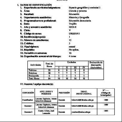
Sylabus Usp 473s59
May 2023 0More Documents from "Pinky Pepy Mulyo" 2h1d4a

Sop Presbiopia 6y5u3h
August 2020 0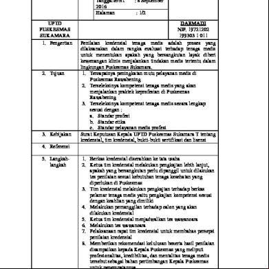
8.7.1.3 Sop Kredensial, Tim Kredensial, Bukti-bukti Sertifikasi Dan Lisensi 683v48
January 2021 0
Dentium-practical Course Training - Sylabus 441f21
August 2021 0
Ppt Materi Gizi Dokter Kecil 2e306c
April 2020 20
Sop Infark Miokard 5h2q5e
May 2020 18