12 Masterbeam Composite Design 5mh5w
This document was ed by and they confirmed that they have the permission to share it. If you are author or own the copyright of this book, please report to us by using this report form. Report 2z6p3t
Overview 5o1f4z
& View 12 Masterbeam Composite Design as PDF for free.
More details 6z3438
- Words: 4,334
- Pages: 20
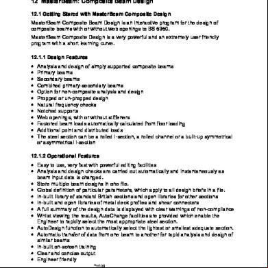
12 MasterBeam: Composite Beam Design 12.1 Getting Stared with MasterBeam Composite Design MasterBeam Composite Beam Design is an interactive program for the design of composite beams with or without web openings to BS 5950. MasterBeam Composite Design is a very powerful and an extremely friendly program with a short learning curve. 12.1.1 Design Features • • • • • • • • • • • •
Analysis and design of simply ed composite beams Primary beams Secondary beams Combined primary-secondary beams Option for non-composite analysis and design Propped or un-propped design Natural frequency checks Notched s Web openings, with or without stiffeners Factored beam loads automatically calculated from floor loading Additional point and distributed loads The steel section can be a rolled I-section, a rolled channel or a built-up symmetrical or asymmetrical I-section
12.1.2 Operational Features • Easy to use, very fast with powerful editing facilities • Analysis and design checks are carried out automatically and instantaneously as beam input data is changed. • Store multiple beam designs in one file. • Global definition of particular parameters, which apply to all design briefs in a file. • In-built library of standard British sections and open libraries for other sections • In-built and open libraries of metal deck profiles and shear connectors • A full summary of the design data is displayed with clear warnings of non-compliance • Whilst viewing the results, AutoChange facilities are provided which enable the Engineer to rapidly select the most appropriate steel section. • AutoDesign function to automatically select the lightest or smallest adequate section. • Automatic transfer of data from one beam to another for rapid analysis and design of similar beams • In-built on-screen training • Clear and concise output • Engineer friendly MasterBeam - Composite design 7 MasterBeam Composite Design
7-1
12.2 Primary Program Interface Regions
The screen above shows four main areas as follows: • The bar menu and tool bar. • The detailed output and graphics area with its scroll bar. • The design summary with the paragraph and section design output navigator spin buttons. • The editing area comprising the five data input tabs: Floor Information, Beam Section, Additional Loads, Web Openings and Open Library. Please note that the information in the detailed output and the design summary areas change dynamically as the beam data is altered in the editing area. 12.2.1 The MasterBeam Tool Bar Create new file using the current defaults Open file Save current file Delete the current brief Copy the current brief to clipboard Add new brief form clipboard Add new brief based on current defaults Enter global editing mode (changes all briefs) Graphics always on top 7 MasterBeam Composite Design
7-2
Next/Previous brief spin button Un-propped during construction stage Propped during construction stage Secondary beam Primary beam with one transverse beam Primary beam with two transverse beam General ( defined) beam Mixed primary secondary beam Apply transverse beams (Primary beams ON/OFF) Use continuous metal deck profile Apply additional point loads Apply additional uniformly distributed load Apply circular web openings Apply rectangular web opening Export / print graphics ON/OFF Project title and Job references Print current brief Print all briefs Export current brief to Word Export all briefs to Word The tool bar provides quick and easy access to some of the primary MasterBeam file management, editing and printing/exporting functions. 12.2.2 The Detailed Design Output and Graphics Area
7 MasterBeam Composite Design
7-3
Graphics The on screen graphics of the current design brief changes dynamically with any modifications to the information in the editing area. The overall graphics scale, as well as the point loads and partial UDL scales may altered using the spin buttons as indicated above. By clicking the Graphics always on top button in the tool bar the graphics will remain visible as you scroll through the design output. Detailed Design Output The design output is presented in a detailed and concise format. The various deign checks are clearly divided into headed sections. The results are generally displayed over four columns, in the format; Column 1 – Description of calculation, item or numerical value. Column 2 – Design data or calculation. Column 3 – Calculation result or permissible values. Column 4 – Design check verdict, OK or Warning. The design output includes; • Summary of design data – details of beam geometry, steel section, metal deck profile, concrete slab, reinforcement, shear connectors, and applied loading. • Section Properties • Ultimate limit state – beam shear, shear connection, axial resistance and moment capacity design checks at critical locations along the beam. • Transverse reinforcement • Serviceability limit state – deflection, steel stress and concrete stress design checks. • Vibration Analysis – natural frequency check • Openings – summary of location and size. Composite / Non-composite moments, Vierendeel moment, axial force design check. Upper and lower web-flange classifications, with axial and shear force capacity checks. Dimensional checks.
12.2.3 Design Summary Area
The design summary area permits immediate evaluation of the fundamental design checks. The unity ratios are dynamically updated with any alteration of information in the editing area. By clicking on any of the items in the design summary area, the corresponding detailed design output is displayed. The paragraph and section navigator spin buttons also provide useful tools for scrolling the detailed design output.
7 MasterBeam Composite Design
7-4
Any unity ratios exceeding 1.0 represent a design failure and are highlighted in red. The background colour of the design output and graphics area also changes to Cyan, making any design failure immediately apparent.
12.2.4 The Editing Area The Editing Area is divided into 6 tabs: Floor Information, Beam Section, Additional Loads, Web Openings, Open Library and Defaults. Analysis and design is carried out automatically and instantaneously as any influential input data is changed.
7 MasterBeam Composite Design
7-5
12.3 Floor Information
or using the Simplified Menu (PowerPad and PowerPad Plus)
12.3.1 Floor Information Input Areas Beam Geometry Main Beam span (primary or secondary) b & c. Distance from main beam to parallel left and right hand beams. For an edge beam either b or c is set to zero. Construction stage The metal deck profile condition at construction stage may be specified as propped or unpropped. In the unpropped condition an ultimate limate state at construction stage design check for shear and moment capacity is applied. Floor Area Loading The general floor area loading in kN/m2 is defined in three categories. The concrete slab and the steel beam self-weights are calculated and added automatically. The program automatically adds 0.2 kN/m2 for Deck/Mesh and 0.5 kN/m2 for Construction Loading. These values may be changed in the defaults tab.
7 MasterBeam Composite Design
7-6
Transverse Beams Defines the position and section size of transverse beams in a primary beam design. The transverse beams apply a concentrated load to the primary beam bases on their length and ed floor width as defined in the beam geometry. The Overwrite Area function enables the to redefined the transverse beam lengths and ed floor widths for each beam. This funtionality is not included where only the simplified menu is available, and the defintion is limited to the application of 1 and 2 No. equedistant transerve beams. Option Buttons Apply design check at construction stage when propped. Displays the defaults tab and the customised program defaults are used Prints the combination of load groups and load factors in the design output Prints steel and concrete stress details in the serviceability limit state design check. Use the simplified input menu only.
12.3.2 Composite Beam Types The design of composite beams is categorised into the following types; 1. Secondary Beam
Represents the beam spanning between two primary beams. The direction of the metal deck profile spans between primary beams. Therefore the in beam graphics the metal deck is shown in section through the hollow rib profile. The number of shear studs is specified per trough.
7 MasterBeam Composite Design
7-7
2. Primary Beam
The primary beams represent the main structural beams. Primary beams may transverse beams. The program automatically calculates the floor area ed by each beam. The Overwrite Floor Area option enables you to specify your own data for special cases. The beam size for the transverse beams is required to enable the correct value of their self-weight to be included. 3. Mixed Primary-Secondary Beam
The mixed – primary secondary option is used for instances where the metal deck profile spans in different direction on either side on the beam. In the above screen, please note: The floor width ed directly by the beam is 1.5 m = ½ the distance to the right hand beam The transverse beam floor length ed is 4.5 m = ½ the distance to the left hand beam
7 MasterBeam Composite Design
7-8
12.4 Beam Section The Beam Section tab defines steel section, metal deck, reinforcement, shear connection, and concrete slab properties.
The steel section type UB, UC, RSJ, UBP, IPE, HE, HL, HD, HPX, IPN, W, …., and Channels. The section size. The section size list can be sorted by serial size or weight order using the Sort check box. The section grade. You can select and add new rolled section types, section sizes and grades in the main open library for steel sections. 3.16 The Steel Sections and Open Library
The metal deck profile condition: Continuous or NonContinuous. The metal deck profile type including solid slab. You can add other metal deck profiles in the Open Library tab. The metal deck profile thickness. The overall concrete slab depth (zero for steel beam only). The concrete grade (zero for non-composite). The area of steel mesh provided perpendicular to the span of the beam. The percentage deck contribution you wish to consider (100% for full contribution, 0% for no-contribution). The wet density of the concrete 1850 for light weight, 2350 for normal weight. The modular ratio. 15 for light weight, 10 for normal weight and 0 to allow the program to calculate a default value based on the concrete type (light or normal weight) and the ratio of the long term and short term loads. The shear connectors type. You can add other shear connectors from the Open Library tab. The shear connectors spacing. In secondary and mixed primary-secondary beams this can be One per Alternate Trough, One per Trough, Two per Trough or Spaced @ the specified centres singly or in pair. In primary beam, the spacing, singly or in pair, can be specified for each region between s and transverse beams Spacing values are used in primary beams where the metal deck profile troughs run parallel with the beam. Spacing_01 7 MasterBeam Composite Design
7-9
refers to the portion between the left-hand and the 1st transverse beam, Spacing_02 refers to the portion between the 1st and the 2nd transverse beams and so on. The last spacing you need to define is between the last transverse beam and right hand . If a spacing is left to a value of zero, then it defaults to the previous value Left and right hand width of concrete flange in composite section b1 and b2. The current brief beam reference title. Add new brief (composite beam design) to data file based on current brief. Delete current brief. The sort spin button moves the position of the current brief in the brief list. AutoDesign button as described below. Increase the number of shear connectors by one. The Ignore Deck Contribution in Primary Beams is provided because BS 5950 is unclear about the contribution. MasterBeam will ignore the contribution if the profile is discontinuous, otherwise the contribution will be assumed to be the same as for a discontinuous profile with ribs running perpendicular to the span of the beam. Using the Auto design The auto design function will attempt to rectify failures related to the beam section and transverse shear. The failures are prioritised in the following order. •
If any failure (with the exception of transverse shear) is detected, the auto design scans through the selected beam section list to find a section which satisfies the failing design criteria.
•
If a transverse shear failure is detected the auto design scans the list of standard steel mesh sizes to find a mesh which satisfies the failing criteria.
7 MasterBeam Composite Design
7 - 10
12.5 Open Library The open library area is used to add new definitions of metal deck profiles and shear connectors. Metal Deck Profiles
Please note that the profile name is limited to 23 characters. Shear Connectors
The shear connector name is limited to 28 characters. To enter an item in the open library Enter the data for the item Be sure to use a new reference number for the item unless you wish to overwrite an existing item Click on Other editing functions Delete the currently selected items from the library. Reset the Standard Library to original MasterBeam values (Metal Deck Profiles No 1 to 14 and Shear Connectors No 1 to 7 Only), Reset the complete library, i.e. delete all defined metal deck profiles and shear connectors. Feel free to investigate the various options provided in the open library, but please be careful not to remove or change properties for items which have been added by other s in your company. If you wish to use the MasterBeam Composite Design on a number of machines then to enter the same items in the open library on all the machines where the program is being used. Alternatively you can copy the open library file C:\msprowd\combeam1.ovr.
7 MasterBeam Composite Design
7 - 11
12.6 Additional Loads
MasterBeam provides the facility to apply: 1. Additional point load positions (X) and values including Dead, Live and Super Imposed Dead; and 2. Additional partially distributed load positions (X1/X2 refer to start/end) and values including Dead, Live and Super Imposed Dead. ! Note: • •
Dead loads are applied at the construction stage before the composite action. Live and Super Imposed Dead loads are applied after the composite action. The “Copy load from” spin buttons enable you to copy loads data from previous or subsequent rows (loads are copied symmetrically on the beam).
Other editing functions Delete the currently active load. Delete all point or partial loading. Mirror copy the loading information from either the line above or below to the current line. The applied point and partial uniformly distributed loading are displayed in the beam graphics. The individual graphical scale of either load may be altered using the spin buttons provided, as described in section 12.2.2 Design Output and Graphics area.
7 MasterBeam Composite Design
7 - 12
12.7 Web Openings
The “Web Openings” area is where you can define: 1. Circular Openings; 2. Rectangular Openings; and 3. Notches at s (special case of rectangular opening).
The distance to the opening is always defined from the left-hand to the centre of the opening in meters. The Top Edge distance is measured from the top of the steel beam to the top edge of the opening The Stiffener Area is the area of one of the two stiffeners provided, one at the top and the other at the bottom of the opening. The two stiffeners are positioned so that their centres are at the specified edge distance from the edge of the opening. The default Edge distance from the centre of a stiffener to the edge of the opening is 12 mm Diameter of the circular wed opening. Depth of rectangular web opening Width of rectangular web opening The program uses default values for the opening diameter, depth, width and the top edge distance. The default values are based on the beam depth and aim at positioning each opening at the centre of the beam. To check the exact values used, use the Section Navigator spin button to view the opening’s data in the detailed output area. A notch at the is a rectangular opening with a distance from the equal to or less than ½ its width. Stiffener sizes and arrangements are suggested in the detailed design output based on the area of stiffener provided and for a compact section. Further guidance for the 7 MasterBeam Composite Design
7 - 13
detailing of stiffeners is given in [2]. Extracts from this technical note [2] concerning the detailing are given in Appendix A. Other editing functions Delete the currently active web opening. Delete all circular or rectangular web openings. Mirror copy the web opening information from either the line above or below to the current line. Option Buttons Use a refined analysis method Recommended check for web openings, where To = axial force arising from non-composite action N1 = number of shear connectors from to start of opening Pd = design strength of the shear connectors Ignore web opening dimensional checks, as outlined in [1]. Show error report on web openings. Please note that some design check options; such as “Ignore dimensional checks in web openings”, must be used at the discretion of the Engineer and should definitely not be used blindly. MasterBeam Composite Beam Design performs the dimensional checks on web openings as outlined in [1]. Additional guidance is provided by [2] which is principally based on [1] but also draws on other publication by AISC and ASCE. Extracts from [2] on this subject are given in Appendix B. Civil and Structural Computer Services would like to acknowledge the co-operation and contribution of the WSP Group in Appendices A and B. We believe the technical content of Appendices A and B provide good best practice guidance, however should be used at the discretion of the design engineer. [1] Lawson, R.M., Design for Openings in the Webs of Composite Beams. Steel Construction Institute, SCI Publication 068, 19812. [2] Stuart Alexander, WSP Group, Strengthening of Web Openings in Steel Beams. Technical Reference Manual 118, Rev 1, 2001.
7 MasterBeam Composite Design
7 - 14
12.8 Customisation of Default Settings
This area can be accessed using the
button on Floor Information Tab.
The may customise; • Load factors for dead, super imposed and live load groups, according to each of the listed design checks. • Construction load and deck self weight. • Minimum natural frequency value • Option to include loading defined in the additional loading tab in the calculation of natural frequency. • Span/deflection ratios. • The load group associated with service and partition floor area loads specified in the floor information tab. Saving customised settings Save the current customised settings to a Master Beam Default (MBD) file, using different file names for different default values. Choose the desired previously saved MBD file, and click Open to active the files default settings. Instantaneously resets to the original MasterBeam program defaults.
7 MasterBeam Composite Design
7 - 15
12.9 Globally Defined Input Values As described in section 12.4 Beam Section, the may save a number of design briefs, i.e. separate beam designs, in one data file. The multiple design briefs may perhaps be associated with a common floor area, floor level or an entire project. MasterBeam provides the facility to globally modify particular parameters for all beam design briefs stored in a single data file. button. Input parameters that can be To enter the global editing mode click on the globally edited are highlighted in Cyan for text boxes and Red for option labels.
Upon modifying a global parameter the program then applies that change to all design briefs in the data file. Once complete the global editing mode is deactivated. Analysis and design is automatically updated. The global editing button must be selected for each individual modification of a global parameter. To exit the global editing without making any changes simply click again on the button to deactivate the mode.
7 MasterBeam Composite Design
7 - 16
12.10 Printing and Exporting Results Export / print graphics ON/OFF Edit Project title and Job references Print current brief Print all briefs Export current brief to Word Export all briefs to Word Sample of Design output exported to PowerPad
7 MasterBeam Composite Design
7 - 17
12.11 Appendix A – Detailing The Stiffeners in Web Openings Appendix A is an extract from the following reference. Stuart Alexander, WSP Group, Strengthening of Web Openings in Steel Beams. Technical Reference Manual 118, Rev 1, 2001. Civil and Structural Computer Services would like to acknowledge the co-operation and contribution of the WSP Group. We believe the technical content of Appendix A provides good best practice guidance, however should be used at the discretion of the design engineer. Strengthening is generally only needed for rectangular openings; it is usually provided in the form of longitudinal stiffeners placed immediately above and below the opening on one or both sides of the web, see figure 1. Vertical stiffeners are not normally required in rolled sections.
Figure 1. Web opening with stiffeners showing elements and dimensions Stiffener section The stiffeners must be sized to be compact, ie the ratio b/Ts T 8.5 for grade 275 and 7.5 for grade 355 steel. Welding Stiffeners must be welded continuously throughout their length. The capacity of the weld from the mid-point to each end of the opening must be at least the yield strength of the stiffener section. Similarly, the capacity of the weld anchoring the extension beyond the opening at each end must also be at least the yield strength of the stiffener section. American publications recommend welding one side only for the length of the opening (ie the side away from the opening) and welding both sides of the extension. This gives convenient geometry in which the extension length is one quarter of the length of the opening. This detail also locates the stiffeners as close to the opening as possible. 7 MasterBeam Composite Design
7 - 18
However, it is likely that the t will widen slightly. If this creates a corrosion risk, welds both sides may be preferable. to leave enough height between the stiffener and the opening to get the weld in, say at least the weld size plus 4 mm. Web strength In order to ensure that the stiffeners are anchored without overstressing the web, the length of the extensions ls must satisfy ls U V3 Ar / 2 t. Shear lag This describes the phenomenon in which at the free end of the stiffener the stress close to the web is very much higher than the stress at the outer edge. Clearly, the longer the extension the more the stress will be able to equalise at the critical section. No guidance on this aspect is provided in any of the quoted publications. However, the tests reported by Lawson et al were carried out with stiffeners 80 x 10 mm extending 150 mm beyond the opening, ie with a ratio ls/b = 1.9. Until further evidence is forthcoming, it is recommended that this limiting ratio is adopted. Stiffeners on one or both sides? The guidance is generally based on stiffeners being located in pairs symmetrically each side of the web. However, the tests reported by Lawson et al were carried out with stiffeners on one side only with no adverse effects observed. The ratio of stiffener width to beam half-flange width in the tests was (b + 0.5 t) / 0.5 B = (80 + 4.8) / 104 = 0.81. It is recommended that paired stiffeners are used if a single stiffener would exceed this ratio. If the stiffeners are predominantly restoring the overall moment capacity (as described above), they should be symmetrical about the web. Equal stiffeners top and bottom? It is theoretically OK to have different stiffeners top and bottom, or even to omit one altogether if the hole is very high or low. Nevertheless, some computer programs can only handle equal stiffeners.
7 MasterBeam Composite Design
7 - 19
12.12 Appendix B – Dimensional Checks in Web Openings Appendix B is an extract from the following reference. Stuart Alexander, WSP Group, Strengthening of Web Openings in Steel Beams. Technical Reference Manual 118, Rev 1, 2001. Civil and Structural Computer Services would like to acknowledge the co-operation and contribution of the WSP Group. We believe the technical content of Appendix B provides good best practice guidance, however should be used at the discretion of the design engineer. For rectangular openings, there are a number of geometric criteria which should be met, as follows: Unstiffened openings should generally have ho T 0.6 D and lo T 1.5 D (SCI 068). Stiffened openings should generally have ho T 0.7 D and lo T 2.0 D (SCI 068; AISC and ASCE require ho T 0.7 D only). Openings should have corner radii r not less than 2 t nor 16 mm (AISC and ASCE). The depths of the upper and lower sections of web sb, st, should not differ by more than a factor of two (SCI 068; AISC and ASCE limits are st U 0.15 D, sb U 0.15 D for non-composite beams or 0.12 D for composite beams). The ratio v = lo / st or lo / sb should not exceed 12 (AISC, ASCE). No opening should be closer to a than 2.0 D or 0.1 L, where L is the span (SCI 068, a notch can be used instead; AISC and ASCE limit is D). Openings should not be less than 1.0 D apart (SCI 068, American practice is more conservative). If openings are closer together, the combined vierendeel action may overload the post between them, see below; this work shows that the lower limit of 1.0 D applies only to openings not requiring stiffeners, and calculations should be carried out for other cases. Point loads should not be applied at less than D from an opening (SCI 068; AISC and ASCE give criteria for reducing this to 0.5 D in some cases, otherwise bearing stiffeners are required. If the point loads arise from secondary beams, fin plate connections can be detailed to create the required stiffeners).
7 MasterBeam Composite Design
7 - 20
Related Documents c2h70
12 Masterbeam Composite Design 5mh5w
October 2021 0
Composite Column Design 345z3s
November 2019 49
Composite Design And Theory 2a163
December 2019 72
(1983)composite Aircraft Design 21f2v
December 2019 104
Design Of Composite Material Flywheel 6r5f12
December 2019 37
Introduction To Composite Materials Design 662y1t
October 2019 50More Documents from "Kishiwa" 45356b
12 Masterbeam Composite Design 5mh5w
October 2021 0
Autodesk Robot Structural Analysis Professional_training f3228
December 2019 210