Vsr Blaster Air Cannon 1c4o43
This document was ed by and they confirmed that they have the permission to share it. If you are author or own the copyright of this book, please report to us by using this report form. Report 2z6p3t
Overview 5o1f4z
& View Vsr Blaster Air Cannon as PDF for free.
More details 6z3438
- Words: 2,219
- Pages: 8
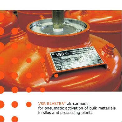
VSR BLASTER® air cannons for pneumatic activation of bulk materials in silos and processing plants
VSR BLASTER® air cannons Filling: Compressed air is supplied to the quick exhaust valve through a small dia. filling and control piping via a 3/2 way hand valve or solenoid valve. The diaphragm in the quick exhaust valve closes the 18 mm outlet. The compressed air flows along the diaphragm into the piston chamber. The outlet pipe is closed by a piston, which is pre-tensioned by a spring. The compressed air flows through the piston orifice into the vessel which is then filled. When the operating pressure is reached the vessel is ready for use as required.
®
VSR BLASTER air cannon Type IV, with internal valve
Release: By reversing the 3/2-way valve, the air supply is interrupted and the control line is vented. The diaphragm in the quick exhaust valve moves back and vents the piston chamber. The piston, having twice the cross section area of the blow pipe, reacts abruptly. When it has travelled only a quarter of the blow pipe diameter the entire cross section is opened. This allows the stored air to flow within milliseconds, explosively through the blow pipe into the silo. Finally the piston is reseated by the pre-tensioning spring which prevents any ingress of material into the air cannon in its depressurized state.
Variations: The alternative to the VSR BLASTER® air cannon with internal valve is the external BOOSTER VALVE. This Booster valve can be installed on every pressure vessel. The unique tapered flange connection with a tension clamp and only two screws allows easy and rapid maintenance of the Booster valve. It is possible to couple two Booster valves to one single pressure vessel, thus giving two adjacent blast positions.
VSR BLASTER® air cannon Type 2EV, with external Booster valves
2
Typical problems and solutions
Funneling
Bridging
Ratholing
Arching
®
High temperature application: riser duct with changeable nozzle system
VSR BLASTER air cannons in a cement plant (Foto: Krupp Polysius)
Effect: ®
The VSR BLASTER air cannon instantaneously expells an explosion charge of compressed air directly into the critical areas of silos, hoppers and heat exchangers. This explosive blast of energy destroys the material adhesion and static friction resulting in a free flow under normal gravity. Air is discharged directly into the material from a straight nozzle or alternatively via a fan shaped head or isobaric sword nozzle in order to spread or concentrate the effort in specific areas. Design advantages: ! The superior effect of the VSR BLASTER® air cannon is achieved by the unrestricted flow of compressed air from
the pressure vessel to the discharge pipe. ! The big piston with twice the diameter of the blowing pipe effects an extremely high piston lifting speed. With a
piston travel of a quarter of the blowing pipe diameter, the ring orifice is fully opened for direct inflow. In this way, the explosive air expansion is achieved. ! Quick exhausting of the piston chamber is done by a large ¾ ” quick exhaust valve with a Viton diaphragm which
is specially developed and directly positioned at the piston chamber. ! Maintenance work on the piston can be carried out without dismounting the vessel by simply removing the
rear cap. ! A spring pushes the piston immediately back and prevents material and dust from penetrating into the vessel.
An impact area at the piston absorbs the recoil. ! Filling and control are carried out through a small Æ 8x1 mm piping which is easily to be installed. Several
control valves can be housed in protective control boxes in easily accessible places. No electric cables have to be connected to the air cannons.
3
VSR BLASTER® air cannons, mounting details and nozzles
Bunker wall concrete or kiln wall
Bunker wall steel
®
®
®
VSR BLASTER air cannon with Spreader nozzle
VSR BLASTER air cannon with Fan jet angle nozzle
VSR BLASTER air cannon (pat.) with Sword nozzle
Basically, VSR BLASTER® air cannons can be installed with all bunker constructions. If necessary, the pressure vessels can be arranged under the silos (e.g. in silo batteries) or in the conveyor tunnel under a stockpile. Openings being about 20 mm bigger than the nominal pipe diameter are cut or drilled into the silo’s walls near the critical non-flowing zones. A thread nipple is mounted in these holes, if necessary with a flange, while pipe extensions or blow nozzles are mounted at the inner side.
At the outside, the air cannon is fastened with a pipe bend by means of a screwed flange set (or a screwed union) and a suspension device.
Depending on the requirements, the air cannon discharges directly or through a blow angle, fan jet angle nozzle, blow head or an isobaric sword nozzle. Where easily fluidizing material can flow far back into the exhaust pipe, a check valve is installed.
Nozzles up to 300°C, DN 50/100/150
Blow pipe
Spreader nozzle
Fan jet angle nozzle
Fan jet blow nozzle
Fan jet blow nozzle, asymmetrical
Slot nozzle
Isobaric sword (pat.) nozzle
Nozzles up to 1200°C, DN 100/150 Changeable nozzle system
Blow head TG
Double blow head TG
Fan jet angle nozzle TG
Fan jet blow nozzle TG
4
Fan jet blow nozzle TG, asymmetrical
Fan jet blow nozzle TG
(pat.)
Fan jet angle nozzle TG
Isobaric sword nozzles and Changeable nozzle system
(pat.)
®
Effect of the isobaric sword nozzle
VSR BLASTER with sword nozzles at a stockpile
The cross section of the isobaric nozzle (pat.) decreases in proportion to flow length. The gap width of the slit is constant, its total cross section corresponds to the blow pipe’s cross section. Thus equal pressure and flow conditions prevail along the entire slit length regardless of whether, how and with what material the sword nozzle is covered.
Thus, a great depth and width effect of the air fan is achieved without loosing the blast effect. Depending on the size of the air cannon, the sword nozzles can be up to 6 m long and formed as single or double sword nozzle. Sword nozzles enhance the effect of the air cannons and reduce the number of blast positions.
It is well known that cloggings of cement raw meal will regularly build up in the heat exchanger of cement rotary kilns. In the past, these had to be removed manually, using air / water lances or poking bars. To carry out this laborious and often dangerous task, the heat exchanger must be completely cooled down.
At that moment or at the latest when the kiln is scheduled to a standstill, the heat exchanger has to be brickworked, the stones and the old nozzles have to be removed and the new ones have to be welded in. As well, the hollow space has to be filled with chamotte cement. To prevent unnecessary damage to the brickwork / lining, the VSR changeable nozzle system has been developed, that allows a simple changing of the nozzle from the outside without inner brickwork lining and possibly without having the heat exchanger completely cooled down. This applies not only for the installation of a completely new heat exchanger refractory but also in case of later equipment.
Nowadays, air cannons are installed at the heat exchanger, their nozzles blowing parallely or perpendicularly to the wall to keep the brickwork or cement lining clean. However, as soon as the mouth piece of a nozzle is affected or worn off by chemical reaction, the cleaning effect decreases.
5
Pneumatic control
VSR Industrietechnik GmbH Am Alten Schacht 6 D- 47198 Duisburg Tel. +49 (0) 20 66 / 99 66-30 Fax +49 (0) 20 66 / 99 66-62 Internet: www.vsr-industrietechnik.de
E-mail: [email protected]
VSR Industrietechnik GmbH Am Alten Schacht 6 D- 47198 Duisburg Tel. +49 (0) 20 66 / 99 66-30 Fax +49 (0) 20 66 / 99 66-62
Internet: www.vsr-industrietechnik.de
E-mail: [email protected]
Solenoid valve case with pressure control and safety aerating
Electronic S7 control unit for large systems
For reasons of safety and effectiveness, in most cases the air cannons are blown off individually. It is best to release them in a cycle one after the other from bottom to top. The actuation frequency depends on the problem. They can be fired every minute or once per hour, shift, day or week.
The solenoid valves are controlled by push buttons, or generally by an electronic cycle control that allows a fully automatic operation. In the simplest form, solenoid valves with adjustable operating time and subsequent interval cycle card are used. A more universal operation, primarily for larger systems, is permitted by using electronic or microprocessor control units. Air cannons should be secured against unauthorized refilling (e.g. during maintenance works).
Ø 8x1 max. 10 m
The firing is initiated by hand lever valves or solenoid valves with auxiliary manual actuation.
4-10 bar
1/2” DN 6 1/4" NO
In general, fill and control tubes not longer than 10 m of stainless steel or copper ø 8x1 are used, with simple applications even polyamid tubes. Cutting ring couplings have to be used to prevent any reduction of the cross section. The hand valves and solenoid valves can be mounted in groups together with an air service device in a well accessible location. Normally, the solenoid valves will be contained in a protective steel cabinet.
6
VSR BLASTER® air cannons K O
N
L
Æ A
Æ C
Æ A
B
B1 M R
®
®
VSR BLASTER Air cannon Type IV, with internal valve
VSR BLASTER Air cannon Type EV1 and EV2, with external valve
Masures and weights
Type = Volume Liter
VB 12 IV
VB 20 IV
VB 33 IV
VB 50 IV VB 50 EV1* VB 50 EV2**
VB 75 IV VB 75 EV1*
VB 100 IV VB 100 EV1*
VB 150 IV VB 150 EV1*
VB 300 IV VB 300 EV1*
VB 500 IV VB 500 EV1*
VB 75 EV2** VB 100 EV2** VB 150 EV2** VB 300 EV2** VB 500 EV2**
ØA
R 2”
R 2”
R 2”
DN100
DN100
DN100
DN100
DN150
DN150
B
516
516
773
822
1022
825
1000
1280
1360
B1
160
160
160
230
230
230
230
230
230
206
276
276
360
360
500
500
650
800
K
-
-
-
746±8
1011±8
830±8
1090±8
1340±8
1390±8
L
-
-
-
219,1
219,1
219,1
219,1
219,1
219,1
M
-
-
-
185
185
185
185
237
237
N
-
-
-
550
550
550
550
800
800
O
-
-
-
638±8
903±8
710±8
970±8
1212±8
1275±8
R
-
-
-
1120±8
1385±8
1204±8
1464±8
1818±8
1868±8
19,4
27,0
60,0 58,0* 81,0**
70,0 68,0* 91,0**
ØC
weight (kg)
16,0
88,0 80,0* 121,0**
101,5 90,0* 131,0**
228,0 190,0* 240,0**
327,0 285,0* 305,0**
Operating pressure max. 10 bar. Temperature TS min. -10°C up to TS max. +120°C. Manufactured according to AD 2000 / DGRL 97/23/EG / TÜV CERT. / EG character: 0044. All dimensions in mm, technical modifications reserved. Please us for detailed information.
12
20
33
50
75
100
150
7
300
500 Liter
Advantages Working medium In most cases, compressed air as supplied by a standard system will be the adequate working medium.
Low Noise level The noise of the expanding compressed air is almost completely absorbed by the bulk material.
The VSR BLASTER® air cannons operate in a pressure range of 4-10 bar with increasing effectiveness. Often, a pressure of 6 bar is sufficient. The operating intervals can be reduced to less than 5 seconds (if necessary), while often only a few blasts per day are needed. If compressed air is not acceptable in the process, inert gas can be used.
Simple Installation and Operation The air cannon is mounted with only a few pipe fittings at the bunker. It will be connected to the compressed air system by means of a 3/2 way valve and can be controlled by an automatic, electronic control .
High temperature and Pressurized vessels VSR BLASTER® air cannons can be used in high temperature and pressurized vessels (up to 1100° C and 6 bar), when special arrangements are provided. Low Energy consumption Since the air cannon operates intermittently, it consumes only a fraction of the energy needed for conventional pneumatic fluidization systems.
Accident prevention The VSR BLASTER® air cannons meet the pressure vessel safety regulations. There is absolutely no danger to the bunker itself nor to its contents. Due to the low volume of compressed air and the use of a sparkless valve, there is no danger of initiating an explosion (e.g. in case of coal dust). Inert gas, e.g. nitrogen, can be used instead of compressed air. Recommendations of the authorized associations for silo safety are available.
Guarantee of Effect VSR BLASTER® air cannon systems, when installed according to our individual recommendations, are guaranteed to perform to the customer's satisfaction, or the components may be returned for full credit within a period to be agreed upon.
Product programme
LINEX® Conveyor belt centralizing idler
DUSTEX® Dust suppression system
CAREX® sealing of conveyor belt transfers
VSR Industrietechnik GmbH Am Alten Schacht 6 D- 47198 Duisburg Tel. +49 (0) 20 66 / 99 66-30 Fax +49 (0) 20 66 / 99 66-62
Internet: www.vsr-industrietechnik.de
E-mail: [email protected]
VIBREX® Conveyor belt cleaning
VIBMATIC 6000® Vibration stress reduction
VSR Industrietechnik GmbH 03/2012 Technical modifications reserved
VSR BLASTER® Air cannons and air injectors
Related Documents c2h70
Vsr Blaster Air Cannon 1c4o43
November 2021 0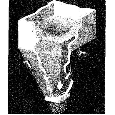
Big Blaster Air Cannons 4m2j3q
November 2022 0
June 2020 6

Concrete Blaster i62r
November 2019 60
Cannon Reil.pdf h1t50
June 2020 3
Master Blaster (jammin') Organ.pdf 652222
April 2020 25More Documents from "kING" 6n4n5e

Uraian Tugas Laundry Rumah Sakit 2o1m4e
April 2020 33
Vsr Blaster Air Cannon 1c4o43
November 2021 0
Uraian Tugas Cssd 4g3x6l
April 2020 26
Dornbusch-fischer-startz-macroeconomics-10.pdf 19672a
December 2019 356
Hirudinaria Granulosa 1t481j
August 2021 0