Types Of Roof Truss And Components Of Root Truss 1r463q
This document was ed by and they confirmed that they have the permission to share it. If you are author or own the copyright of this book, please report to us by using this report form. Report 2z6p3t
Overview 5o1f4z
& View Types Of Roof Truss And Components Of Root Truss as PDF for free.
More details 6z3438
- Words: 1,436
- Pages: 4
Types of Roof Truss and Components of Root Truss
Introduction When sloping roofs have to be provided, roof trusses become necessary . At places of heavy rainfall or heavy snowfall, sloping roofs are necessary which have to be ed by roof trusses. Workshops warehouses, industrial buildings etc. also need sloping roofs and hence roof trusses. For many single storey buildings sloping roofs on trusses are common. When a roof is to be provided for a building which does not have interior s and the exterior walls are more than 12 m apart, a roof truss will be a convenient arrangement to the roof. Components
of
a
Steel
Roof
Truss
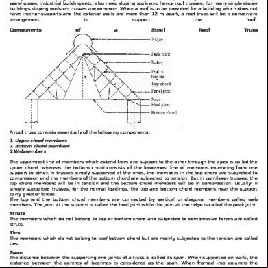
A roof truss consists essentially of the following components; 1. Upper chord 2. Bottom chord 3.Web The uppermost line of which extend from one to the other through the apex is called the upper chord, whereas the bottom chord consists of the lowermost line of extending from one to other. In trusses simply ed at the ends, the in the top chord are subjected to compression and the of the bottom chord are subjected to tension. But in cantilever trusses, the top chord will be in tension and the bottom chord will be in compression. Usually in simply ed trusses, for the normal loadings, the top and bottom chord near the carry greater forces. The top and the bottom chord are connected by vertical or diagonal called web . The t at the is called the heel t while the t at the ridge is called the peak t. Struts The which do not belong to top or bottom chord and subjected to compressive forces are called struts. Ties The which do not belong to top/ bottom chord but are mainly subjected to the tension are called ties. Span The distance between the ing end ts of a truss is called its span. When ed on walls, the distance between the centres of bearings is considered as the span. When framed into columns the distance between the column faces is regarded as span. Rise The rise of a truss is vertical distance between apex and line ing the s. Pitch The ratio of the rise to the span is called the pitch. A minimum pitch of 1/6 is to be maintained for G.I. sheet covering and expected and 1/12 is to be maintained for AC sheet covering.The preferable pitch is
1/4
if
snow
load
is
expected
and
1/6
if
snow
load
is
not
expected.
Pitch = Rise/Span
Types of Roof Trusses The triangle is the primary pin ed frame which has a stable figure. Hence, all trusses should comprise triangular figures various types of trusses are used shown below. The king post truss is mainly adopted for short spans (up to 6 m). It is usually built of wood completely or of wood combined with steel. Steel rods are used as tension . The queen post truss is found suitable for spans 6 m to 9 in. For ordinary buildings, the link type truss is found to be very satisfactory. These trusses are convenient for spans 12 m to 18 m. For small spans, flat roofs may be ed on beams. But for larger spans, flat trusses are to be used. In this case, the upper chord will be inclined sufficiently to provide just the required slope for proper drainage. In factory buildings where considerably more light is desirable, the saw tooth truss is used. In this type, the sleep sides of the trusses will be glazed. The glazed s are usually faced towards North to avoid the direct glare of the sun and are hence called North light roof trusses. For long spans and where more head room has required the crescent, the truss is adopted. For such conditions the scissors truss, the curb truss, the shed truss, the three hinged arched truss, the Hammer beam truss are also used.
Purlins As far as possible, purlins should be located on points off top chord . However, it depends on the type of roofing materials also. Generally, the spacing of purlins varies from 1.35 m to 2.0 m. Angle iron purlins are used for smaller spacing of trusses (3 to 4 m). For medium spacing (4 to 5 m) one use channels and for still larger spans, I - sections may be used. If angles are used, outstanding legs are at the top and lug angles are used to connect the purlins to rafters.
Sheetings Commonly used sheeting is G.I. and A.C. G.I. Sheets Corrugated iron sheets are galvanized for protection against corrosion and are used as roof coverings. The common sizes of G.I. sheets are; 1. 8 corrugations, 75 mm wide and 19 mm deep which have an overall width of 660 mm. 2. 10 corrugations, 75 mm wide and 19 mm deep, which have an overall width of 810 mm. The sheets are available in the gauges 16, 18, 20, 22 and 25 Note: thickness = 25/ gauge mm The sheets area available in lengths 1.8 m, 2.2 m, 2.5 m, 2.8 m and 3.0 m. The sheets should be used with the following overlaps. Side laps: 1, 3/2 or 2 corrugations.
End laps: 100 mm, if a slope is more and 150 m, if a slope is less than 20°. For lesser overlaps, suitable sealings should be made. The sheets should be fastened to purlins or sheeting rails by 8 mm diameter hook bolts at a maximum pitch of 350 mm. The spacing of purlins depends on the applied loading, thickness of sheets and length of sheets. For common loading, the thickness of sheetings is so fixed that, with required overlaps the sheetings can be used fully. A.C. Sheets Asbestos cement sheets are better insulators for Sun's heat compared to GI sheet. They are used commonly in the factories and godowns. They are available in two common shapes i.e, corrugated and Trafford. They are available in the lengths of 1.75, 2.0, 2.5 and 3.0 m. They are available in thicknesses of 6 mm and 7 mm. The maximum permissible spacing is 1.4 m for 6 m sheets and 1.6 m for 7 mm sheets. They are to be used with a longitudinal overlap of 150 mm and a side overlap of one corrugation spacing of purlins is to be adjusted such that as far as possible the cutting of sheets is avoided
8.2 Loads on Roof Truss
The main loads on roof trusses are; i) Dead Loads ii) Imposed Loads iii) Wind Loads iv) Other Loads Dead Loads It includes the weight of sheetings, purlins, bracings, self-weight and other loads suspended from trusses. The unit weight of various materials are given in is 875-part 1. The following values may be noted; GI Sheets: 85 N / m2 AC Sheets: 130 N / m2 In general, the roof covering weight including laps, connector etc. may be taken as, i) 100-150 N / m2 for G.I. sheeting ii) 170-200 N / m2 for A.C. sheeting The weight of purlins should be added after deg purlin. Generally, it works out 100-120 N / m 2 of the plan area. On lower points additional occasional load may be considered. Such load is due to electrical fixtures, fans etc. This may be assumed to be 5 to 10 KN, distributed over lower points. If the false ceiling is to be suspended that load should be estimated separately. There are various formulae suggested in the literature to assume the self-weight of truss. However, since it is a small percentage of total load anyone of them may be used. The following are the two formulae commonly used for a truss of span 'l'. a) If a live load is more, the above value is to be increased by LL / 2.0.
b) where, S is the spacing of trusses. Imposed Load (Live load) Normally, no access is provided for sloping roofs with a sheet. In such cases IS 875 part II makes the following provisions for live loads for the design of sheets and purlins. Up to 10° slope = 0.75 KN / m2 For more than 10° slope = 0.75 - 0.02 (θ-10) , where, θis slope of sheeting. However, a minimum of 0.4 kN / m2 live load should be considered in any case.
For the design of trusses, the above live load may be reduced to 2/3 rds. The purlins and sheets should be checked to a concentrated load of 0.9 KN at the worst position.
Introduction When sloping roofs have to be provided, roof trusses become necessary . At places of heavy rainfall or heavy snowfall, sloping roofs are necessary which have to be ed by roof trusses. Workshops warehouses, industrial buildings etc. also need sloping roofs and hence roof trusses. For many single storey buildings sloping roofs on trusses are common. When a roof is to be provided for a building which does not have interior s and the exterior walls are more than 12 m apart, a roof truss will be a convenient arrangement to the roof. Components
of
a
Steel
Roof
Truss
A roof truss consists essentially of the following components; 1. Upper chord 2. Bottom chord 3.Web The uppermost line of which extend from one to the other through the apex is called the upper chord, whereas the bottom chord consists of the lowermost line of extending from one to other. In trusses simply ed at the ends, the in the top chord are subjected to compression and the of the bottom chord are subjected to tension. But in cantilever trusses, the top chord will be in tension and the bottom chord will be in compression. Usually in simply ed trusses, for the normal loadings, the top and bottom chord near the carry greater forces. The top and the bottom chord are connected by vertical or diagonal called web . The t at the is called the heel t while the t at the ridge is called the peak t. Struts The which do not belong to top or bottom chord and subjected to compressive forces are called struts. Ties The which do not belong to top/ bottom chord but are mainly subjected to the tension are called ties. Span The distance between the ing end ts of a truss is called its span. When ed on walls, the distance between the centres of bearings is considered as the span. When framed into columns the distance between the column faces is regarded as span. Rise The rise of a truss is vertical distance between apex and line ing the s. Pitch The ratio of the rise to the span is called the pitch. A minimum pitch of 1/6 is to be maintained for G.I. sheet covering and expected and 1/12 is to be maintained for AC sheet covering.The preferable pitch is
1/4
if
snow
load
is
expected
and
1/6
if
snow
load
is
not
expected.
Pitch = Rise/Span
Types of Roof Trusses The triangle is the primary pin ed frame which has a stable figure. Hence, all trusses should comprise triangular figures various types of trusses are used shown below. The king post truss is mainly adopted for short spans (up to 6 m). It is usually built of wood completely or of wood combined with steel. Steel rods are used as tension . The queen post truss is found suitable for spans 6 m to 9 in. For ordinary buildings, the link type truss is found to be very satisfactory. These trusses are convenient for spans 12 m to 18 m. For small spans, flat roofs may be ed on beams. But for larger spans, flat trusses are to be used. In this case, the upper chord will be inclined sufficiently to provide just the required slope for proper drainage. In factory buildings where considerably more light is desirable, the saw tooth truss is used. In this type, the sleep sides of the trusses will be glazed. The glazed s are usually faced towards North to avoid the direct glare of the sun and are hence called North light roof trusses. For long spans and where more head room has required the crescent, the truss is adopted. For such conditions the scissors truss, the curb truss, the shed truss, the three hinged arched truss, the Hammer beam truss are also used.
Purlins As far as possible, purlins should be located on points off top chord . However, it depends on the type of roofing materials also. Generally, the spacing of purlins varies from 1.35 m to 2.0 m. Angle iron purlins are used for smaller spacing of trusses (3 to 4 m). For medium spacing (4 to 5 m) one use channels and for still larger spans, I - sections may be used. If angles are used, outstanding legs are at the top and lug angles are used to connect the purlins to rafters.
Sheetings Commonly used sheeting is G.I. and A.C. G.I. Sheets Corrugated iron sheets are galvanized for protection against corrosion and are used as roof coverings. The common sizes of G.I. sheets are; 1. 8 corrugations, 75 mm wide and 19 mm deep which have an overall width of 660 mm. 2. 10 corrugations, 75 mm wide and 19 mm deep, which have an overall width of 810 mm. The sheets are available in the gauges 16, 18, 20, 22 and 25 Note: thickness = 25/ gauge mm The sheets area available in lengths 1.8 m, 2.2 m, 2.5 m, 2.8 m and 3.0 m. The sheets should be used with the following overlaps. Side laps: 1, 3/2 or 2 corrugations.
End laps: 100 mm, if a slope is more and 150 m, if a slope is less than 20°. For lesser overlaps, suitable sealings should be made. The sheets should be fastened to purlins or sheeting rails by 8 mm diameter hook bolts at a maximum pitch of 350 mm. The spacing of purlins depends on the applied loading, thickness of sheets and length of sheets. For common loading, the thickness of sheetings is so fixed that, with required overlaps the sheetings can be used fully. A.C. Sheets Asbestos cement sheets are better insulators for Sun's heat compared to GI sheet. They are used commonly in the factories and godowns. They are available in two common shapes i.e, corrugated and Trafford. They are available in the lengths of 1.75, 2.0, 2.5 and 3.0 m. They are available in thicknesses of 6 mm and 7 mm. The maximum permissible spacing is 1.4 m for 6 m sheets and 1.6 m for 7 mm sheets. They are to be used with a longitudinal overlap of 150 mm and a side overlap of one corrugation spacing of purlins is to be adjusted such that as far as possible the cutting of sheets is avoided
8.2 Loads on Roof Truss
The main loads on roof trusses are; i) Dead Loads ii) Imposed Loads iii) Wind Loads iv) Other Loads Dead Loads It includes the weight of sheetings, purlins, bracings, self-weight and other loads suspended from trusses. The unit weight of various materials are given in is 875-part 1. The following values may be noted; GI Sheets: 85 N / m2 AC Sheets: 130 N / m2 In general, the roof covering weight including laps, connector etc. may be taken as, i) 100-150 N / m2 for G.I. sheeting ii) 170-200 N / m2 for A.C. sheeting The weight of purlins should be added after deg purlin. Generally, it works out 100-120 N / m 2 of the plan area. On lower points additional occasional load may be considered. Such load is due to electrical fixtures, fans etc. This may be assumed to be 5 to 10 KN, distributed over lower points. If the false ceiling is to be suspended that load should be estimated separately. There are various formulae suggested in the literature to assume the self-weight of truss. However, since it is a small percentage of total load anyone of them may be used. The following are the two formulae commonly used for a truss of span 'l'. a) If a live load is more, the above value is to be increased by LL / 2.0.
b) where, S is the spacing of trusses. Imposed Load (Live load) Normally, no access is provided for sloping roofs with a sheet. In such cases IS 875 part II makes the following provisions for live loads for the design of sheets and purlins. Up to 10° slope = 0.75 KN / m2 For more than 10° slope = 0.75 - 0.02 (θ-10) , where, θis slope of sheeting. However, a minimum of 0.4 kN / m2 live load should be considered in any case.
For the design of trusses, the above live load may be reduced to 2/3 rds. The purlins and sheets should be checked to a concentrated load of 0.9 KN at the worst position.
Related Documents c2h70
Types Of Roof Truss And Components Of Root Truss 1r463q
November 2019 140
Design Of Steel Roof Truss 1u271e
May 2020 12
Modeling Of Howe Roof Truss 4kt4n
November 2022 0
Proposal Of Polynesian Roof Truss 243a2z
December 2019 59
Roof Truss Design Procedure 6s5p1d
December 2019 94
North Light Roof Truss 3wa2q
October 2019 170More Documents from "sagar" 1o6y3s
Types Of Roof Truss And Components Of Root Truss 1r463q
November 2019 140
About Sikta 6v2n1f
December 2019 65
Ap Bifurcation Bits.pdf 6h4s1x
October 2019 118
4. Project Report Intelligent Breaking System 2 6a3b4d
November 2019 34
Gjxpfib1 2t2s4m
November 2019 38