Transmission Mechanical Training 16f1k
This document was ed by and they confirmed that they have the permission to share it. If you are author or own the copyright of this book, please report to us by using this report form. Report 2z6p3t
Overview 5o1f4z
& View Transmission Mechanical Training as PDF for free.
More details 6z3438
- Words: 8,974
- Pages: 190
TRAINING TIPS AND TACTICS
Transmissions Manual
1
2
Contents General information
Clutch
Epicyclic gearsets Use IMPACT
11 19
Designation Double plate clutch Plate centring Centring lugs Clutch servo operation Clutch wear indicator Later type servo Disc wear limit Wear calculations example Energy dissipation Bleeding the clutch system
23 25 27 29 31 33 35 35 35 37 39
Volvo Gearbox Designation Gearbox sections Gearset configuration Gearset shafts Synchroniser - VT Gʼbox Selection forks Selector housing - SR1900 Selector housing - VT Gʼbox Gear identification - splitter & main gearset Splitter gearset Range change gearset Powerpath 8/9 speed range change gearbox Lubrication Oil pump & filter Oil fill/level
43 45 47 47 53 55 57 59 61 63 63 65 67 69 71 71
3
Volvo Gearbox - cont. Air system Supply air filter - pre VT Gʼbox Air system - gear selector Range change cylinder Relay valve - range change cylinder Range change air circuit - & inhibitors Neutral lock valve Pre-selection Inhibitor cylinder & valve Low range engaging - gear engaged High range engaging - gear engaged High range selecting - gearbox in neutral
73 75 77 79 81 83 85 85 87 91 93 95
Volvo Gearbox - cont. High range engaged - gear engaged Modification- range change - inhibitor cylinder operation Modification - additional - function, inhibitor cylinder operation Splitter gear air circuit - & inhibitors Pre-selection Splitter cylinder Relay valve - splitter cylinder Splitter inhibitor valve High split requested - clutch pedal not pressed High split engaging - clutch pedal pressed High split engaged - clutch pedal released
97 99 101 103 103 105 107 109 111 113 115
4
Volvo Gearbox - cont. Low split requested - clutch pedal released Low split engaging - clutch pedal pressed Electrical components - location & function Modification - cable gear shift Eaton Gearbox Designation 1st. and 2nd. gear - synchroniser ZF Gearbox Designation Low range inhibitor 1st. gear inhibitor
117 119 121 125 133 135 139 139 141
Propeller shafts Torque transfer Main components Universal t t angle Yoke alignment bearing Lubrication Drive axle General Designation Final drive - main components Crown wheel & pinion Crown wheel & pinion - ratio Crown wheel thrust block Differential Drive shafts Differential lock Double reduction Tandem drive
145 147 149 151 151 153 153 157 159 161 163 165 167 169 171 173 177 183
5
6
Introduction About this Pocket guide
This guide is intended as a memory jogger for the knowledge you have gained during your training course. The guide includes a summary of the material covered in:
Transmissions - Manual
7
Danger, Warning, Caution & Note
In this guide, risk of injury or damage is indicated by the following headings: DANGER - indicates a risk of serious personal injury or death. WARNING - indicates a risk of personal injury, or severe product damage. CAUTION - indicates risk of product damage. Note - draws attention to special methods or particular features. Read and implement all DANGER, WARNING and CAUTION instructions.
8
Replacement parts
When replacement parts are required, it is essential that only Volvo genuine parts are fitted. If Volvo genuine parts are not used: - safety features embodied in the vehicle or components may be impaired. - performance and/or operation of the vehicle or components may be adversely affected. - Volvo warranty may be invalidated.
9
Specification
Volvo are constantly seeking ways to improve their products, and alterations take place accordingly. Whilst every effort has been made to ensure the accuracy of this guide, it should not be regarded as an infallible guide to current specifications of any product. Neither Volvo, nor the supplier of this guide shall, in any circumstances, be held liable for inaccuracy or the consequences thereof.
Copyright
C
All rights reserved. No part of this publication may be reproduced, stored in a retrieval system, transmitted or copied without written permission from Volvo Truck & Bus Ltd. Volvo Truck & Bus Ltd. 2006
10
General Information 11
General Information R
P
PC
S 12
General Information Epicyclic gearsets
The range change unit uses a gear arrangement called an ʻepicyclicʼ or ʻplanetaryʼ gearset. The gearset has four main components: R - ring gear, or annulus P - planet gear (orbits the sun) S - sun gear PC - planet carrier Each of these components can be the input, the output, or can be held stationery. The role each component plays determines the gear ratio for the gearset. Locking any two components together locks up the gearset, and gives a 1:1 ratio.
13
General Information R
P
PC
S 14
General Information Epicyclic gearsets example
Calculations
In the single gearset above, the ring gear has 72 teeth, and the sun gear has 30 teeth. These combinations can produce the following ratios: Input
Output Stationary Gear ratio
Sun
Planet carrier
Ring
3.4:1A
Planet carrier
Ring
Sun
0.71:1B
Sun
Ring
Planet carrier
-2.4:1C
A 1 + R/S Reduction - output speed slower than input speed B 1/(1 + S/R) Overdrive - output speed faster than input speed C -R/S Reduction - output direction reversed
15
General Information
PC
S P
R
1
2 16
General Information Gearing examples
R - ring gear, or annulus P - planet gear (orbits the sun) S - sun gear PC - planet carrier In the upper illustration, the ring gear is locked to the housing (1) and, in this case, gives a reduction of 3.75:1. In the lower illustration, the planet carrier is locked to the ring gear (2). Therefore, the whole gearset rotates as a unit and, in this case, gives direct drive - 1:1. Other combinations of this single gearset will produce other ratios.
17
General Information
43
4 Power transmission 40 General 41 Clutch 42 Special gearbox 43 Gearbox 45 Propeller shaft 46 Rear axle, drive shaft 48 Power take-off 49 Miscellaneous
FH12
431.....................
18
General Information Use IMPACT
To ensure that you are using the latest information especially ʻSpecificationsʼ - always get your information via IMPACT: Power transmission - Group 4
19
20
Clutch 21
Clutch
B
CL 43 S O CS 43 B O* 22
Clutch Clutch designations
KB 1 15
Clutch, single, 15in.
CL 43 S O CS 43 B O*
Clutch, single, 430 mm, organic lining material.
CL 43 S O R CS 43 B OR*
Clutch, single, 430 mm, organic lining material, reinforced.
CL 38 D O CD 38 B O*
Clutch, double, 380 mm, organic lining material.
CL 40 D O CD 40 B O*
Clutch, double, 400 mm, organic lining material.
* New designations apply from week 02.2002. Note: Version (B) has ʻinvoluteʼ splines, which means that the splines are cut with a slight curvature from tip to root. The splines are also finer. 23 The splines must not be greased.
Clutch 5
6 3
1
2
4 24
Clutch Double plate clutch
1. Release bearing. 2. Pressure plate. 3. Intermediate pressure plate. 4. Clutch disc. 5. Centring lugs x 4. 6. Spring straps.
25
Clutch
7
2
T 5
1
4
6 3
E 26
Clutch
Plate centring
Equalised clearance
1. Pressure plate - intermediate. 2. Centring lugs. 3. Spring strap - attached to (1). 4. Pressure plate - main. 5. Spring strap - attached to (4). 6. Lug attachment bolts 7. Spring strap cover E. To engine flywheel T. To transmission.
When the release bearing is pulled back to disengage the clutch, the force of the diaphragm spring is overcome, and the main pressure plate moves away from the first disc. The intermediate pressure plate is pushed away from the second disc by spring straps (3) and (5). Centring lugs (2) now press against spring strap (5). The retraction forces, acting on the two pressure plates, are now equalised. This ensures that the clearance at both sides 27 of each disc is equal.
Clutch 7
2
T 5
1
4
6 3
E 28
Clutch Centring lugs
CAUTION Centring lugs (2) must not be moved or adjusted when new discs are fitted. The lugs must be adjusted only if the pressure plate has been dismantled. 1. Assemble the clutch and fit it to the flywheel. 2. Remove lug attachment bolts (6), clean the bolts and apply high temperature resistant glue (Loctite 640). 3. Quickly push the lugs against spring strap (5). Fit the bolts, and tighten to 26.0 +/- 2.0 Nm. CAUTION Lugs (2) should be in tight with the spring strap covers (7). There must be no clearance or pre-pressure.
29
Clutch 2
3
5 1
4 7
8
6
30
Clutch Clutch servo cylinder operation
When clutch pedal (1) is pressed, hydraulic pressure increases, pushing up reaction piston (2). This movement first closes air inlet valve at upper seat (3), and then cuts off outlet valve (4). Rubber peg (5) is lifted from its seat, allowing pressurised air to enter chamber (6) and push actuation piston (7) forwards. Release lever (8) rotates to disengage the clutch.
31
Clutch
A
1
32
Clutch Clutch wear indicator
As the clutch plates wear, the piston moves further into the cylinder. When dimension ʻAʼ reaches 32 mm, the piston touches, and progressively pushes out, wear indicator valve (1). When this point is reached, air will be heard leaking from the valve, and servo assistance will be reduced.
33
Clutch
2 X1
X2
Y
D
X1 X2
1 34
Clutch
Later servo cylinder
With the later servo cylinder arrangement, the cylinder is attached directly to the clutch housing (1). The clutch release fork is carried on a spherical bearing (2). The pedal force is 110 Nm, and the pedal stroke is 160 mm.
Disc wear limit
The discs must be renewed when the thickness is down to: - single disc - 34 mm. - double disc - 36 mm.
Wear calculation - example
The dimension measured is from the front face of the clutch housing to the front face of the release arm. X1 = 65 mm - when the clutch is new X2 = 100 mm - when the clutch is worn Wear = 100 - 65 = 35 mm - (Y) on the chart
35
Clutch = Level = 12% gradient
1400 1200 1000 0
C
800 600 400 200 0
C
1LS
1HS
2LS
2HS
3LS
3HS
36
Clutch Energy dissipation in a clutch
The chart above shows the heat generated when starting off in each gear.
Rapid wear
At temperatures greater than 2000 C, rapid lining wear occurs.
Irreversible damage
At temperatures greater than 4500 C, irreversible damage to the lining occurs.
37
Clutch
3
4
2
5 1
38
Clutch Bleeding the clutch system - using bleed unit (9996928)
1. Place the bleed unit (1) in a vessel containing clutch fluid. 2. Remove the rubber cap from bleed nipple (2) on the clutch servo unit. 3. Connect the hose to the bleed unit, and open the bleed nipple. 4. Connect the electric cable to the cigarette lighter socket (3). 5. Remove the cover from the fluid reservoir (4). 6. Press bleed unit switch to ON to start the pump. 7. Allow the pump to run until the fluid is at the correct level in reservoir (4). 8. Close the bleed nipple. 9. Disconnect the hose and refit the rubber cap. 10. Check the fluid level and refit the reservoir cover. 11. Check that the clutch operates correctly.
39
40
Volvo Gearbox 41
Volvo Gearbox
42
Volvo Gearbox Designations
SR1900 - Split, Range, 1900 Nm max. input torque VT2014 - Volvo Transmission, 2050Nm max. input torque, 14 forward ratios. VT2514B - Volvo Transmission, 2450Nm max. input torque, 14 forward ratios, involute splines on input shaft. VTO2514B - Volvo Transmission, Overdrive, 2450Nm max. input torque, 14 forward ratios, involute splines on input shaft. T700A - Eaton transmission, 700Nm max. input torque, A/B ratio. R800 - ZF transmission, range change, 800Nm max. input torque
43
Volvo Gearbox
C
S
M
R
44
Volvo Gearbox Gearbox sections
The gearbox assembly has four main sections: C. Clutch housing. S. Splitter gearset. M. Main gearsets R. Range change gearset.
45
Volvo Gearbox
2 1
4
3
46
Volvo Gearbox Gearset configuration
The gearset configurations in the VT2014/2514 gearboxes are similar to that in the SR1700/1800 gearboxes: - 14 forward ratios - 12 synchronised forward ratios - 2 crawler gears - 4 reverse gears - not synchronised
Gearbox shafts
1. Input - or ʻprimaryʼ shaft. The front end of the shaft is splined, and carries the clutch discs. The input shaft transmits drive from the engine to the gearbox. 2. Main shaft - carries the synchronised gears, each of which is free to turn on a bearing. The front end of the shaft is carried in the input shaft on a taper roller bearing. The rear end carries the sun gear of the range change gearset.
47
Volvo Gearbox
2 1
4
3
48
Volvo Gearbox Gearbox shafts
3. Intermediate shaft - also known as the ʻcountershaftʼ or ʻsecondaryʼ shaft - carries gears which mesh with those on the mainshaft. High and low splitter gears are a tight press fit on the shaft. The other gears are integral with the shaft and - therefore, all gears always turn together at shaft speed. The front and rear end of the shaft is carried on taper roller bearings. The shaft is driven by the input shaft, and transfers torque to the main shaft via the gears in mesh. 4. Reverse shaft - carries the reverse gear . The reverse gear is an ʻidlerʼ gear, integral with the hollow reverse shaft. The gear is positioned between a driving gear on the intermediate shaft and a driven gear on the mainshaft. This arrangement reverses the direction of rotation of the intermediate shaft so that, when engaged, the reverse gear turns the main shaft in the opposite direct to the input shaft.
49
Volvo Gearbox
2 1
4
3 5
50
Volvo Gearbox Gearbox shafts
5. Output shaft - the planet carrier of the range change gearset is integral with the output shaft.
51
Volvo Gearbox
1
2
3
4
5
6
7
9
10
8
52
Volvo Gearbox Synchroniser - VT gearboxes
1. Gear ring 2. Inner ring 3. Washer 4. Outer ring 5. Synchroniser ring 6. Plate spring 7. Engaging body 8. Coupling sleeve 9. Spring pins - gear selected 10. Spring pins - neutral selected
VT gearboxes have an improved type of ʻdoubleʼ synchroniser. The unit has a self-energising effect, similar to that found with the leading shoe of a brake assembly. This effect reduces the effort needed to change gear by up to 50%. The unit is narrower, allowing the use of wider gears, which increases the acceptable max. input torque.
53
Volvo Gearbox 3
1
2
4 54
Volvo Gearbox Selector forks
Selector forks (1) are attached to selector bars (2), which are moved back and forth by selector shaft (3). The back and forth movement is transferred to synchroniser sleeves (4) which engage the gears.
55
Volvo Gearbox
5
4 3
2
1
56
Volvo Gearbox Selector housing - SR 1900
1. Control shaft 2. Gear position detent 3. Gear change inhibitor 4. Selector lever 5. Reverse gear detent
57
Volvo Gearbox
2
1
4 3
58
Volvo Gearbox Selector housing - VT range
This selector housing is similar to that used with SR 1900. The following features are different: 1. Inhibitor solenoid - prevents unintentional engagement of 1st. gear when low ratio range change is selected. This could cause over-speeding of the clutch and geartrain components. 2. Inhibitor solenoid - prevents selector from moving from neutral position to a gear engaged position when the clutch is engaged. 3. Reverse light switch 4. Combined gear position and reverse interlock
59
Volvo Gearbox
HS 1
LS
2 C
R
3
RI 60
Volvo Gearbox Gear identification splitter and main gearset
1. 1st. gear 2. 2nd. gear 3. 3rd. gear LS. Low range splitter HS. High range splitter C. Crawler gear R. Reverse gear RI. Reverse idler gear
61
Volvo Gearbox C
4 1
R
5 2
R
6 3
S
62
Volvo Gearbox Splitter gearset
Range change gearset
The splitter gearset, at the front of the main geartrain, is used to select high or low splitter ratio. The splitter gearset splits the main gearset ratio by half. The range change gearset, at the rear of the main gearset, is a planetary gearset. When low ratio range change is selected, the ring gear is locked to the gearbox housing, and gives a ratio reduction. When high ratio range change is selected, the planet carrier is locked to the ring gear, and gives a direct drive.
63
Volvo Gearbox
LS
HS
1
2
C
R
RC
64
Volvo Gearbox Power path
The illustration above shows an example of the power path through the gearbox - in this case the selected ratios are: - 1st. gear - Low splitter - Low range change
65
Volvo Gearbox
4
3 1
2 C
R
66
Volvo Gearbox 8/9 speed range change gearbox
The 8/9 speed gearbox, illustrated above, is similar to the 14 speed gearbox: - in the 8 speed gearbox, there is no splitter gear or crawler gear. Four base gears + range change = 8 speed - in the 9 speed gearbox, there is a crawler gear, but no splitter gear. Four base gears + range change + crawler = 9 speed.
67
Volvo Gearbox
4 5 1
2
3
68
Volvo Gearbox Lubrication
Lubrication of the gearbox is a combination of oil splash, generated by the rotating components, and pressure feed from the oil pump. The pump is gear driven by the intermediate shaft (1). The drive gear is carried on a shaft (2) which es through the hollow reverse gear shaft, and into the oil pump (3). Approx. 70% oil from the pump lubricates and cools range change components (4), and approx. 30% lubricates and cools the mainshaft and input shaft (5). CAUTION The oil pump is not driven when the vehicle is being towed. Therefore, the prop. shaft must be removed before towing begins. Do not coast with the gearbox in neutral. In this situation, the mainshaft is not rotating, so the oil pump is not being driven. 69
Volvo Gearbox
3
4
2
1
A
70
Volvo Gearbox Oil pump and filter
1. Pressure relief valve - system high pressure protection. 2. Pressure relief valve - filter by-. 3. Filter tube. 4. Filter cartridge. A. Oil cooler
Oil fill/level
An oil filler/level plug - with sight glass - and a drain plug are located on the side of the gearbox housing.
71
Volvo Gearbox 2 5
8
4 10 6 3
1 9
11
7 72
Volvo Gearbox Air system
1. Range change cylinder 2. Splitter cylinder 3. Range OK valve (ROK) - on range change cylinder 4. Neutral lock valve on selector housing 5. Inhibitor valve - splitter 6. Inhibitor cylinder on selector housing 7. Relay valve - range change cylinder 8. Relay valve - splitter cylinder 9. Solenoid valve - range change inhibit 10. Air filter (VT gearbox) 11. Gear lever
73
Volvo Gearbox 10
12
74
Volvo Gearbox Supply air filter - pre. VT gearbox
A sintered air filter (10) is fitted in-line, in the supply pipe from distribution block (12), which is fed from (MV) 4way valve port 24. A blocked filter causes slow gear-change and clutch actuation.
75
Volvo Gearbox
1 21 3 22 76
Volvo Gearbox Air system - gear selector
Port numbers: 1. Supply to selector 3. Exhaust from range change cylinder - shift to high range 21. Supply to range change cylinder relay valve - shift to low range 22. Supply to splitter relay valve
77
Volvo Gearbox
2
5
3
7 4 1
6
78
Volvo Gearbox Range change cylinder
The range change cylinder is a double acting cylinder attached to the rear of the gearbox housing. 1. Rubber seal 2. Piston seals 3. Piston rod rubber seal 4. Cylinder to gearbox housing seal 5. Relay valve cap seals 6. Adjusting shims* 7. Relay valve *CAUTION To ensure that the selector fork cam rollers fit correctly in the sliding dog clutch, it is essential that the cylinder position - in relation to the rear face of the gearbox housing - is correctly adjusted by adding or removing shims.
79
Volvo Gearbox
HR
LR
12
AA
AA
CA
7
80
Volvo Gearbox Relay valve - range change cylinder
Relay valve (7) is located in the rear cover of the range change cylinder. Control valve plunger (12) is spring loaded to ʻhighʼ range position (HR). In this position, actuation air (AA) from the neutral lock valve can into the cylinder and move the piston to high range position. When ʻlowʼ range is selected, control air (CA) is supplied from the gear lever to the relay valve. Spring force is overcome, and the plunger moves up to ʻlowʼ range position (LR). In this position, actuation air (AA) from the neutral lock valve can into the cylinder and move the piston to low range position.
81
Volvo Gearbox H
1
3
11 CA
H
L
7
L 9
4
13
6 82
Volvo Gearbox Range change - air circuit and inhibitors
1. Range change cylinder 3. Range OK valve (ROK) on range change cylinder 6. Inhibitor cylinder on selector housing 7. Relay valve - range change cylinder 9. Solenoid valve - range change inhibit 11. Gear lever 13. Gear selector lever Control air (CA) is supplied to range change cylinder relay valve (7) from gear lever port (21), via solenoid valve (9). If the speed of the output shaft exceeds approx. 700 rev/min. - approx. 30 km/h - a signal from the tachograph energises a relay which, in turn, energises solenoid valve (9). The air supply to range change cylinder relay valve (7) is now cut-off, preventing selection of low ratio range change.
83
Volvo Gearbox 7 AA
4
13 14
A
1
14
13
B
84
Volvo Gearbox Neutral lock valve
The neutral lock valve (4), on the selector housing, prevents a range change when any gear in the main gearbox is engaged. When the main gearbox is in neutral (A) the valve is open, and actuation air (AA) can to the range change cylinder relay valve (7). When any gear is engaged (B) valve plunger (14) is pushed in by selector lever (13), and the actuation air supply to the range change cylinder is cut-off.
Pre-selection
Using the gear lever switch, a range change is pre-selected whilst a gear is engaged in the main gearbox. Because of the operation of neutral lock valve (4), at this point, no range change takes place. The change takes place only when neutral is selected in the main gearbox. 85
Volvo Gearbox 6
13
3
19 18 15
16
17
86
Volvo Gearbox Inhibitor cylinder and valve
The inhibitor cylinder (6), on the selector housing, prevents a gear change in the main gearbox when a range change is taking place. Air flow to the cylinder is controlled by ROK valve (3) on the range change cylinder housing. Range change piston rod (15) has two detents - (16) for low range, and (17) for high range. When a range change is taking place, ROK valve plunger (18) is pushed into the valve, opening a path for air to to cylinder (6). Inhibitor cylinder plunger (19) is pushed out into the detent in selector lever (13), effectively locking the main gearbox in neutral.
87
Volvo Gearbox 6
13
3
20
19
15
18
16
17
88
Volvo Gearbox Inhibitor cylinder and valve
When either low or high range is engaged, ROK valve plunger (18) is pushed out and sits in one of the detents. The air path to cylinder (6) is now closed. Spring (20) retracts cylinder plunger (19), allowing selector lever (13) to rotate to engage a gear.
89
Volvo Gearbox
H
1
3
11 CA
L
H
L 9
AA
4
7
13
6 90
Volvo Gearbox Low range engaged - gear engaged
The illustration above shows low range engaged, with a gear engaged in the main gearbox. When low range was selected using the gear lever switch, control air (CA) from the gear lever, via solenoid (9), moved the plunger of relay valve (7) to low range position. When neutral was selected in the main gearbox, actuation air (AA) was allowed to enter the chamber, and push the piston to the right to engage low ratio. Because a gear is now engaged, neutral lock valve (4) has now cut off the actuation air supply to relay valve (7).
91
Volvo Gearbox
H
11
1
3
CA
H
7
L 9
L
4
13
6 92
Volvo Gearbox High range requested - gear engaged
1. Range change cylinder 3. Range OK valve (ROK) on range change cylinder 4. Neutral lock valve 6. Inhibitor cylinder on selector housing 7. Relay valve - range change cylinder 9. Solenoid valve - range change inhibit 11. Gear lever 13. Gear selector lever The illustration above shows high range requested, with a gear engaged in the main gearbox. By selecting high range, control air (CA) has been exhausted from relay valve (7), via solenoid valve (9), and the gear lever exhaust port. Because neutral lock valve (4) is closed by selector lever (13), air cannot to relay valve (7), so high range cannot be engaged.
93
Volvo Gearbox 1 H
11
7
3 H
L
L 9
4
13
6 94
Volvo Gearbox High range selecting - gearbox in neutral
1. Range change cylinder 3. Range OK valve (ROK) on range change cylinder 4. Neutral lock valve 6. Inhibitor cylinder on selector housing 7. Relay valve - range change cylinder 9. Solenoid valve - range change inhibit 11. Gear lever 13. Gear selector lever The illustration above shows high range being selected, with the main gearbox in neutral. Neutral lock valve is now open, so actuation air (AA) can to relay valve (7). The valve plunger is already at ʻhighʼ position, so actuation air enters behind the piston. The piston starts to move to the left. Because the plunger of ROK valve (3) is not in a detent, the valve is open, and air is fed to inhibitor cylinder (6), locking selector lever (13) in neutral position.
95
Volvo Gearbox H
11
1 3
CA
H
L
L 9
AA
4
7
13
6 96
Volvo Gearbox High range engaged - gear engaged
1. Range change cylinder 3. Range OK valve (ROK) on range change cylinder 4. Neutral lock valve 6. Inhibitor cylinder on selector housing 7. Relay valve - range change cylinder 9. Solenoid valve - range change inhibit 11. Gear lever 13. Gear selector lever The illustration above shows high range engaged, with a gear engaged in the main gearbox. By selecting high range, control air (CA) has been exhausted from relay valve (7), via solenoid valve (9), and the gear lever exhaust port. This allowed actuation air (AA) to enter the chamber, and push the piston to the left to engage high ratio. Because a gear is now engaged, neutral lock valve (4) has cut off the actuation air supply to relay valve (7).
97
Volvo Gearbox 1 B
2 A
98
Volvo Gearbox Modification - range change inhibitor cylinder operation
The modification, illustrated above, alters the way inhibitor cylinder (B) operates. The gear selector is inhibited only during a range change, whilst the gear lever is in neutral position. Modification introduced: - A583353 - B368368 - Gearbox serial No. 20041160015 1. Pipe - air supply to neutral sensing valve 2. Pipe - air supply to range change cylinder. A. Gear selector B. Inhibitor cylinder
99
Volvo Gearbox 6
B
11
7 13
A
AA
AA
5
100
Volvo Gearbox
Modification - additional function inhibitor cylinder operation
5. Inhibitor valve - splitter 6. Inhibitor cylinder 7. Splitter cylinder
11. Gear lever 13. Gear selector lever
On early systems inhibitor cylinder (6) is used only with the range change function. On later systems, inhibitor cylinder (6) has an additional function - to prevent gear selection or change without pressing the clutch pedal. When neutral is selected in the main gearbox, and the clutch pedal is not pressed, the spring of cylinder (6) pushes the plunger into the detent in selector lever (13), preventing gear selection (A). When the clutch pedal is pressed, actuation air (AA) can from inhibitor valve (5) to the underside of inhibitor cylinder (6). The force of the spring of cylinder (6) is overcome. The plunger is retracted, allowing gear selection (B).
101
Volvo Gearbox H 11
8
21
L
H
L
2 5
102
Volvo Gearbox Splitter gear air circuit and inhibitors
2. Splitter cylinder 5. Inhibitor valve - splitter 8. Relay valve - splitter cylinder 11. Gear lever 21. Indicator lamp - low splitter engaged In the illustration above, the splitter gear is in low ratio. Indicator lamp (21) is lit.
Pre-selection
Using the gear lever switch, a split change is pre-selected before the clutch pedal is pressed. Because of the operation of inhibitor valve (5), at this point, no split change takes place. The change takes place only when the clutch pedal is pressed, and the clutch is disengaged.
103
Volvo Gearbox 8
25
21
22 H
L
23 24
104
Volvo Gearbox Splitter cylinder
The splitter cylinder is a double acting cylinder attached to the side of the selector housing. Splitter piston rod (22) has two detents - (23) for high range, and (24) for low range. Spring loaded plunger (25) locks the rod in either high or low split position.
105
Volvo Gearbox AA
26 CA
8
22
LS
HS
106
Volvo Gearbox Relay valve splitter cylinder
Relay valve (8) is located in the rear cover of the splitter cylinder. Control valve plunger (26) is spring loaded to ʻlowʼ split position (LS). In this position, actuation air (AA) from the splitter inhibitor valve can into the cylinder and move piston (22) to low split position. When ʻhighʼ split is selected, control air (CA) is supplied from the gear lever to the relay valve. Spring force is overcome, and the plunger moves to ʻhighʼ split position (HS). In this position, actuation air (AA) from the from the splitter inhibitor valve can into the cylinder and move the piston to high split position.
107
Volvo Gearbox
AA
8
5
HS
108
Volvo Gearbox Splitter inhibitor valve
To prevent damage to components, the splitter gear must be changed only when the clutch is not engaged. Actuation air (AA) is therefore supplied to the splitter relay valve via inhibitor valve (5). When the clutch pedal is pressed, and the clutch disengaged, the valve is open, so actuation air (AA) can reach relay valve (8). Note: As long as the clutch pedal is pressed - clutch disengaged - a split change can take place irrespective of whether the main gearbox is in neutral, or a gear is engaged.
109
Volvo Gearbox H 11
8
21 CA
L
H AA
5
L
2 110
Volvo Gearbox High split requested clutch pedal not pressed
2. Splitter cylinder 5. Inhibitor valve - splitter 8. Relay valve - splitter cylinder 11. Gear lever 21. Indicator lamp - low splitter engaged The illustration above shows high split requested, with the clutch pedal not pressed. By selecting high split, control air (CA) is fed to relay valve (8). The valve plunger moves to high split position, and uncovers the exhaust port. Because inhibitor valve (5) is closed, actuation air (AA) air cannot to relay valve (8), so the split change cannot take place.
111
Volvo Gearbox H 11
8
21 CA 25
L
22
23
AA 2 5
112
Volvo Gearbox High split engaging - clutch pedal pressed
2. Splitter cylinder 5. Inhibitor valve - splitter 8. Relay valve - splitter cylinder 11. Gear lever 14. Splitter cylinder 17. Indicator lamp - low splitter engaged The illustration above shows high split engaging, with the clutch pedal pressed. By selecting high split, control air (CA) is fed to relay valve (8). The valve plunger has moved to high split position, and uncovers the exhaust port. Because the clutch pedal is pressed, inhibitor valve (5) is now open, so actuation air (AA) air can to relay valve (8), so the split change takes place. Detent plunger (25) is pushed into the high split detent (23) and piston rod (22) is locked in this position.
113
Volvo Gearbox H 11
8
21 CA 25
L
22
23
AA 2 5
114
Volvo Gearbox High split engaged - clutch pedal released
2. Splitter cylinder 5. Inhibitor valve - splitter 8. Relay valve - splitter cylinder 11. Gear lever 21. Indicator lamp - low splitter engaged The illustration above shows high split engaged, with the clutch pedal released. The detent plunger (25) is pushed into the high split detent, (23) and piston rod (22) is locked in this position.
115
Volvo Gearbox H 11
8
21 CA 25
L
CA
22 AA
5
23
2 116
Volvo Gearbox Low split requested - clutch pedal released
2. Splitter cylinder 5. Inhibitor valve - splitter 8. Relay valve - splitter cylinder 11. Gear lever 14. Splitter cylinder 17. Indicator lamp - low splitter engaged The illustration above shows low split requested, with the clutch pedal released. Moving the gear lever switch to low split position has opened an exhaust path for control air (CA) to escape from relay valve (8) via gear lever port (3). This allows the relay valve spring to push the plunger to low split position. Because inhibitor valve (5) is closed, actuation air (AA) cannot to relay valve (8), so the split change cannot take place.
117
Volvo Gearbox H 11
8
21 CA 25
L
22 AA
5
24
2 118
Volvo Gearbox Low split engaging - clutch pedal pressed
2. Splitter cylinder 5. Inhibitor valve - splitter 8. Relay valve - splitter cylinder 11. Gear lever 21. Indicator lamp - low splitter engaged The illustration above shows low split engaging, with the clutch pedal pressed. Actuation air (AA), from the high split chamber is escaping from the exhaust port of relay valve (8). Because inhibitor valve (5) is now open, actuation air (AA) can to relay valve (8), and into the low split chamber. The piston rod (22) moves to the left to engage low split ratio. The detent plunger (25) is pushed into the low split detent, (24) and piston rod (22) is locked in this position.
119
Volvo Gearbox
XXX
S49
S47, S49, XXX, S63
S63
Y06 S47
Y31
BO9
B12
120
Volvo Gearbox Electrical components - location and function
S47 (214) Switch - high split indicator lamp S49 (217) Switch - reverse light activation Y06 (614) Solenoid - range change inhibitor B12 (7052) Sensor - output shaft speed - signal to tachograph S63 (2074) Sensor range position - signal to VECU to energise solenoid (Y31) Y31 (6050) Solenoid, 1st. gear inhibit - prevents selection of 1st. gear if shift speed is too high XXX Sensor - neutral position - signal to VECU (Option) B09B (762) Sensor - oil temperature (Option)
121
Volvo Gearbox 1494
6050 Y31
Y31 6050
214 S47
B09B 762
S49 217
B12 7052
614 Y06 2074 S63
1499 GB1494 GA1494 122
Volvo Gearbox Electrical components - location and function
S47 (214) Switch - high split indicator lamp S49 (217) Switch - reverse light activation Y06 (614) Solenoid - range change inhibitor B12 (7052) Sensor - output shaft speed - signal to tachograph S63 (2074) Sensor range position - signal to VECU to energise solenoid (Y31) Y31 (6050) Solenoid, 1st. gear inhibit - prevents selection of 1st. gear if shift speed is too high XXX Sensor - neutral position - signal to VECU (Option) B09B (762) Sensor - oil temperature (Option)
123
Volvo Gearbox
1 4
3
2
124
Volvo Gearbox Modifications cable gear shift
Cable gear shift has been introduced on the following gearboxes - some of the designations are new: VT1708B, VT2009B, VTO2214B, VT2514B, VTO2514B Gear lever carrier (1) is available in three versions: - FH, as in the illustration above - FM. LH - FM, RH The carrier is attached to the cab floor, with cables (2) and (3) connected below.
125
Volvo Gearbox
1 4
3
2
126
Volvo Gearbox
Modifications cable gear shift
The ʻpush/pullʼ cables transmit the actuation force and motion from the gear lever to control housing (4). Cable (2) is coloured ʻgreyʼ and controls the gear shift stroke. Cable (3) is coloured ʻblack, and controls gear selection. The cables are routed under the cab floor towards the front of the vehicle, around the cab mounting pivot, along the LH side of the frame, to the control housing on the gearbox. Cable attachments are coloured: - Black - gear select, carrier. - White - gear shift stroke, carrier. - Blue - gear shift stroke, control housing. - Orange - gear select, control housing. To ensure smooth shift characteristics, each end of the cables is connected via “quick-lockʼ rubber couplings.
127
Volvo Gearbox 4
6
1 3
7
5
2
128
Volvo Gearbox Modifications cable gear shift Control housing
There is no cable adjustment - the mechanism has a tolerance of approx. +/- 15 mm. Control housing (4) is similar to that used with VT2014. Arm (5) controls gear shift stroke. Arm (6) controls gear select. Balance weight (7) helps improve gear shift quality.
129
130
Eaton Gearbox 131
Eaton Gearbox
132
Eaton Gearbox Eaton gearbox
Designations
Eaton gearboxes are fitted to FL6 vehicles.
-T 600 A/B
max. input torque different ratio sets
-T 700 A/B
max. input torque different ratio sets
-T O 800
overdrive max. input torque
133
Eaton Gearbox
4
5 8
1
2
3
2
1
6 7 3 134
Eaton Gearbox 1st. and 2nd. gear synchroniser
Double friction surface
1. Synchroniser cone inner ring 2. Synchroniser cone centre ring 3. Synchroniser cone outer ring 4. Operating sleeve
5. Inhibitor peg and spring 6. Engaging hub 7. Inner and outer cone holder 8. Engaging ring
A ʻdoubleʼ synchroniser unit is used for 1st. and 2nd. gears. The synchroniser cone is in three parts - inner (1), centre (2) and outer (3). This arrangement provides a double friction surface - both sides of centre cone (2). The synchroniser is, therefore, able to provide effective synchronisation for high torque input. The inner and outer cones rotate with engaging hub (6). The centre cone rotates with engaging ring (8).
135
136
ZF Gearbox 137
ZF Gearbox 1
2
138
ZF Gearbox ZF Gearbox
ZF gearboxes are fitted to FL6 vehicles.
Designation
R 800
Low range inhibitor
range change max. input torque
The range change inhibitor prevents engagement of low ratio when road speed is > 30 km/h. The inhibitor is controlled by solenoid (614A).
139
ZF Gearbox
3
2 140
ZF Gearbox 1st. gear inhibitor
2. Inhibitor control solenoid - 614B 3. Inhibitor air cylinder 1st. gear inhibitor prevents accidental selection of 1st. gear when shifting from 5th. to 4th. At road speeds > 20 km/h, solenoid (2) is energised, allowing actuation air to to cylinder (3). Actuation of the cylinder increases the force required to move the gear lever between 3/4 and 1/2.
141
142
Propeller Shafts 143
Prop shafts
A
B 144
Prop shafts Torque transfer
A prop. shaft transfers torque output by the gearbox to the driving axle. Depending on the wheelbase of the vehicle, more than one prop. shaft may be fitted (A). This arrangement is often required to ensure acceptable operating angles for the universal ts. If the vehicle has two driving axles, a second prop. shaft transfers torque from one to the other (B).
145
Prop shafts 2
1
2
1
3 4 1a 146
Prop shafts Main components
1. Coupling flange - one at each end, used to attach the shaft to the gearbox output flange, and the drive axle input flange. To increase torque capacity, and reduce metal fatigue, the mating faces of most flanges are grooved (1a). 2. Universal t - one at each end, used to allow the shaft to rotate through changing angles. 3. Main shaft - made from tubular steel, which gives greater strength than a solid shaft. Tubular shafts can withstand a considerable amount of twist without fracture. 4. Sliding shaft - connected to the gearbox end of the main shaft by splines. The slip t accommodates changes in overall shaft length caused by up and down movement of the drive axle.
147
Prop shafts 2
4 3
1 148
Prop shafts Universal t
This is a flexible t which allows the prop. shaft to transmit torque from the gearbox, at an angle which varies with up and down movement of the drive axle. The central cross-shaped component (1) is often called the ʻspiderʼ. Each of the four spider journals is surrounded by needle roller bearings, carried in cups (2). Two cups are located in the yoke of the coupling flange (3), and the other two are located in the yoke of the prop. shaft (4). This is a simple coupling t which is ʻnon- constant velocityʼ. This means that, as the t angle changes, so does the speed of the output shaft, even though the input shaft is rotating at a constant speed. The greater the angle between the two shafts, the greater the speed fluctuation.
149
Prop shafts
A
900
B
150
Prop shafts t angle
Yoke alignment
Generally, the operating angles (A) of all ts should be the same, and as small as possible. However, the angle should be large enough to ensure that the bearing needles rotate and move around the journals. By correctly alignment of the yokes at each end of the shaft assembly, the ts are ʻin-phaseʼ (B), and speed fluctuation is eliminated. CAUTION If the prop. shaft assembly is separated at the slip t, it is essential that the two parts of the assembly are marked, so that the t can be refitted in exactly the right position.
151
Prop shafts
2
1
152
Prop shafts bearing
When more than one prop. shaft is fitted, the point at which the two shafts connect must be ed. is provided using a ʻʼ or ʻcentreʼ bearing. The ball bearing (1) may be single or double track - usually ʻsealed-for-lifeʼ - carried in a rubber sleeve in a bracket (2). The bracket is attached to a frame cross-member.
Lubrication
Slip t - early shaft assemblies have a grease nipple for lubrication of the t splines. Later assemblies are lubricated during manufacture with a special grease, or have a nylon coating on the splines. These ts must not be greased. Spider bearings - a grease nipple is fitted to each spider, and channels in the spider carry grease to the 153 bearings.
154
Drive Axle 155
Drive axle
1 2
156
Drive axle Drive axle general
The drive axle forms the final part of the power transmission train. This is where the final increase in torque, and reduction in engine speed occurs. The main central gear assembly (1) is often called the ʻfinal driveʼ. The main functions of the axle are: - Provide the final, major, gear reduction. - Turn the drive direction through 900 . - Provide a means for the inner and outer wheels to turn at different speeds when going round bends. The main axle housing (2) is attached to the frame via the suspension components.
157
Drive axle
1 2
158
Drive axle
Rear
Axle designations
Axle
Enkel (Single) Vaxel (Gear)
RAEV90 RAN - Rear hub reduction CTEV87 - Tandem drive axle CTN - with hub reduction RS1344SV - Rear, single 13T axle = 44T Gross
159
Drive axle 2
3 1
4 3
160
Drive axle Final drive - main components
1. Crown wheel - located between the two halves of the differential carrier. 2. Pinion - the input shaft. The crown wheel and meshed pinion together turn the drive through 900. 3. Drive shafts (also referred to as ʻhalf shaftsʼ) - transfer the drive from the differential assembly to the hubs. 4. Differential assembly - allows the inner and outer wheels to turn at different speeds when going round bends.
161
Drive axle
A
B
162
Drive axle Crown wheel and pinion
The crown wheel and pinion are ʻbevelʼ gears, used specifically to transmit the drive through 900. They are matched together, and marked, during manufacture, and must only be used together. The use of unmatched pairs will result in noisy operation and short life. There are two common tooth profiles for the crown wheel and pinion:
Spiral bevel Hypoid
A. Shows a ʻspiral bevelʼ arrangement, where the pinion centre line coincides with the crown wheel centre line. B. Shows a ʻhypoidʼ arrangement, where the pinion centre line lies below the crown wheel centre line. With the hypoid curve of the teeth faces, the pinion gear is larger, and more teeth are in , increasing the torque capacity of the axle. Most Volvo axles use hypoid cut gears. 163
Drive axle
A
B
164
Drive axle Crown wheel and pinion - ratio
The prop. shaft speed is much higher than that required for the road wheels. In addition, the torque at the prop. shaft is too low to turn the road wheels under heavy load. The crown wheel and pinion drop the prop. shaft speed by quite a large ratio - typically between 2.5:1 and 5.0:1. This ratio change also increases the torque fed to the road wheels E.g.
No. of teeth on crown wheel = 30 No. of teeth on pinion = 10
Ratio = 30 / 10 = 3:1 The speed is reduced by a factor of 3, and the torque is increased by a factor of 3.
165
Drive axle
1 3 4 2
166
Drive axle Crown wheel thrust block
Because of the large diameter of the crown wheel, and side thrusts exerted by high torque, a thrust block (1) is fitted by the side of crown wheel (2) opposite pinion (3). The position of the thrust block is adjusted by screw (4). The block is adjusted so that, in normal operation, there is a slight clearance between the block and crown wheel face. The block makes with the crown wheel face under conditions of heavy loading.
167
Drive axle 2 1
2
1
3
168
Drive axle Differential
When a vehicle is cornering, the outer wheels have to travel a greater distance than the inner wheels, so they must rotate faster, but still transmit equal torque to each wheel. The gear arrangement that allows this to happen is called a ʻdifferentialʼ. The main components are: 1. Bevel pinions x 4 2. Sun - or side - bevel gears. These gears have internal splines, into which the drive shafts are located. 3. Spider
169
Drive axle
1 3
2 170
Drive axle Drive shafts
The drive shafts (1) - also called ʻhalfʼ shafts - transmit torque from the differential side bevel gears to the hubs. The shafts are subject to extreme twisting forces. They are made of special steel with elastic properties that can withstand constant twisting - up to almost one whole turn - before breaking. In a single reduction axle, the outer ends of the shafts have an integral driving flange (2) which is bolted to the hub. If the axle has secondary ʻhub-reductionʼ the outer ends have splines (3) which mesh with the planetary gears of the hub reduction gearset.
171
Drive axle CAUTION To prevent component damage: - Engage the diff. lock only when on slippery surfaces, and a tyre is losing grip. - Vehicle must be stationary before diff. lock is engaged.
8 3
6 7
4
1 5
2 172
Drive axle Differential lock
When the friction on the driving wheels is not equal - e.g. if one tyre is on a slippery surface - the differential action can be prevented using a differential lock When locked, the differential will rotate as a complete unit, causing both driving wheels to rotate at the same speed. 1. Fixed coupling sleeve - is attached the differential housing, and cannot rotate. 2. Sliding coupling sleeve - is located over a splined section of one drive shaft. 3. Diaphragm 4. Actuation sleeve 5. Shift fork 6. Indicator lamp switch 7. Push-rod 8. Return spring
173
Drive axle
+
A
+
7
A 9 E
E
DE 174
Drive axle Diff. lock operation
9. Solenoid valve A. Air supply E. Air exhaust
Diff. lock engaged - E
When the diff. lock is engaged, using a switch on the dashboard, solenoid (9) is energised and air is fed to the control cylinder. Air pressure acts on the diaphragm, sleeve and push-rod, tilting the shift fork towards the crown wheel. The sliding coupling meshes with the fixed coupling, and the differential is locked. The indicator lamp switch is actuated and the dashboard lamp is lit.
Diff. lock disengaged - DE
Solenoid (7) is de-energised, cutting off the cylinder air supply. The push rod spring returns the shift fork and coupling to disengaged position. 175
Drive axle
176
Drive axle Double reduction
Hub reduction
Extremely high torque is required to propel a heavy truck - the heavier the truck load, the more torque is required. In conjunction with the large diameter of the driving wheels and tyres, there comes a point where it is impractical to use a single reduction drive axle to achieve the required reduction ratio. Also to be considered is ground clearance. The higher the reduction ratio provided by the crown wheel and pinion, the larger is the crown wheel diameter. Housing a large crown wheel requires a very deep axle centre bowl, which reduces ground clearance. A solution to this problem is ʻdouble reductionʼ. The ʻprimaryʼ reduction is still via a crown wheel and pinion, followed by a ʻsecondaryʼ reduction. A common and compact form of secondary reduction is ʻhub reductionʼ.
177
Drive axle
4 3
5
2 1
178
Drive axle Hub reduction
Secondary reduction at the hub is achieved by using a planetary gearset. Sun gear (1) is spline mounted on drive shaft (2). Ring gear (3) is spline mounted on axle housing (4) so cannot rotate.
179
Drive axle
5 6
5
180
Drive axle Hub reduction Operation
Advantages
Planet gears (5) are free to rotate on shafts integral with of planet carrier (6), which is attached to the hub. Because the ring gear is locked to the housing, when the drive shaft and sun gear rotate, the effect is to drive the planet gears around the inside of the ring gear. The planet gears rotate on their shafts and, because the shafts are fixed in the planet carrier, the whole carrier must also rotate. The carrier, and the attached hub, therefore form the output member. The achieved gear reduction ratio is - 3.46:1. Advantages of this form of double reduction are: - less torsional stress on the drive shafts - smaller diameter crown wheel and, therefore, shallower axle bowl.
181
Drive axle
A
182
Drive axle Tandem drive
For a number of reasons a truck may need two driving axles - legal requirements (weight distribution), load carrying capacity, extra traction provided by more driving wheels. A typical arrangement, illustrated above, is called a ʻtandem driveʼ bogie. The forward axle (A) has the addition of a ʻtransfer gearʼ arrangement. The rearmost axle has a conventional single reduction differential assembly.
183
Drive axle
4
12
11
10
8
9
13
A
B 8
1
2
3
4
5
6
7
184
Drive axle Tandem drive - main components
1. Forward axle input flange 2. Inter-axle differential 3. Forward axle pinion 4. Forward axle drive shafts 5. Forward axle differential 6. Transfer shaft 7. Rear axle crown wheel 8. Rear axle drive shafts 9. Rear axle differential 10. Rear axle pinion 11. Forward axle Crown wheel 12. Forward axle pinion drive gears 13. Inter-axle differential lock
185
Drive axle
4
12
11
10
8
9
13
A
B 8
1
2
3
4
5
6
7
186
Drive axle Transfer gear assembly
Different axle speeds
The transfer gear assembly drives the pinion of the forward axle via a pair helical gears (12). Transfer shaft (6) transfers drive to the rear axle input flange. In the same way that driving wheels at each side of a single drive axle must be allowed to rotate at different speeds, so two driving axles must be allowed to rotate at their own speed. A simple example of how different axle speeds may occur is if the tyres on one axle were markedly different diameter than those on the other axle. The axle with the largest diameter tyres would need to rotate at a slower speed than the axle with smaller diameter tyres. Axle speeds may also differ, when tyres have 187 unequal traction - e.g. on soft ground.
Drive axle
4
12
11
10
8
9
13
A
B 8
1
2
3
4
5
6
7
188
Drive axle Inter-axle differential
To allow different axle speeds, an ʻinter-axleʼ or ʻthirdʼ differential (2) is required. The ʻthird diff.ʼ is located in the forward axle housing. One of the differential side bevel gears is integral with the forward axle helical drive gear (12) for the pinion. The other side bevel gear is integral with transfer shaft (6). The third diff. divides speed and torque equally between both axles. This can lead to a problem. If only one driving wheel spins, because of ice or soft ground, the vehicle will not move because the third diff. divides torque equally. This problem is overcome by fitting a differential lock (13) to the third diff.
189
190
Related Documents c2h70
Transmission Mechanical Training 16f1k
October 2020 0
Mechanical Drives And Power Transmission Training 5o5j1i
October 2019 35
Mechanical Design Of Transmission Line 1n2r3w
November 2021 0
Mercedes Training Mechanical 6o4r19
April 2020 27
Mechanical Engineering - Training Report 283755
December 2019 115
Ansys Mechanical Training 6h4q6t
November 2019 56More Documents from "Sherzad Chem" 282e4b
Fh12 Fh16 Rhd Wiring Diagram 3m4ns
November 2021 0
Electrics Training 3y3q3x
November 2020 0
Transmission Mechanical Training 16f1k
October 2020 0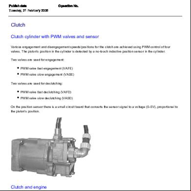
Clutch Cylinder With Pwm Valves And Sensor.pdf 724n7
November 2021 0
6g3p1u
November 2020 0