Torques Motor 3066 2t31c
This document was ed by and they confirmed that they have the permission to share it. If you are author or own the copyright of this book, please report to us by using this report form. Report 2z6p3t
Overview 5o1f4z
& View Torques Motor 3066 as PDF for free.
More details 6z3438
- Words: 10,784
- Pages: 29
r CATERPIILAR'
sENR5s45-03 January1999
Sloc@ffiil@atnons 3064 and 3066 Engines For Gaterp¡llar b Built Machines 6LK1-Up(Engine) 7JK1-Up(Engine)
i
{ j
,J
320i8, 32OE L, 32OB U, 32OB LU EXGAVATORS& 32OB LL FOREST HACI{INES Volume I (Engine, Electrical, Operation and tlaintenance) 4NRl-Up, SBRl-Up, 6GRl-Up' lDSl.Up' lESl.Up' 6LSl.Up' EESI-Up, gGSl-Up, 9JSl-Up' 4XWl-Up' SGWI.Up' 3tRl-UP' 4H Rl -Up, 9KR{ -Up' I GSI -U p' 2rII21.Up, 7ZZ1 -Up, 8G21.Up, AEDI-Up, BANI-Up, BBGI -Up
sENR9242-12 Contents for Service Manual SENR924O
Thisformliststhe completeServiceManualforthisproduct.Theitemslistedcan be orderedseparately. Note¡ and shouldbe orderedas they added,theywill be announcedin PREVIEW Whenitemsare updatedor supplements for contentsand form current REG1139F, Manual microfiche, Contents to the Service Refer available. become numbersof thismanual. Scction
\-,
Title
Binder BinderLabel Safety ServiceManualContents Torqr.reSpecifications Engine Index Tab 3066Engine ErgineSpecifications Testingand Adjusting 3066Engine SystemsOperations, 3066Engine andAssembly Disassembly Engine 3066 Supplement and Assembly Disassembly Elecfical S¡rsterns & Ope¡atoÉs Station Index Tab Control Engineand PumpElectronic SystemsOperation System Startingand Charging SystemsOPeration ElectricalSystem Schemat¡c ElectricalSystem;ForestMachines Schematic (6151-Up, 9JS1-Up) (7721-UP Electrical System Schematic BBGl-Up) 8GZ1-Up, taintenance lndex Tab Operationand Maintenance -Up,9JS1'Up) (6LS1 ForestMachines Operationand Maintenance -UP, -Up, -Up, (721 BANI 8GZ1 Operationand Maintenance BBGl-Up)
Form No, SENR23OO SENR9241 SENR7733 SENR9242 SENR3130 SENR,2ETO SENR5545 SENR5546 SENR5553 SENR9243 sENRil996 RENR1998 RENRlOOT SENR9258 RENR1O58 RENR3725 SENRiIET4 sEBU6975 SEBU7O79 XEBU2571
For Systemsinformation, see Engine,Electrical& Maintenance information. This manualcontains Note: page RENR2982. Contents
03/09/00
CATERPILIAR'
10056692
lmportantSafety Information
-,
r r ec a u s e c= ; ' . - ' = - . M o s ta c c i d e n ttsh a ti n v o l v pe r o d u cot p e r a t i o m n ,a i n t e n a n caen d r e p a i a o b s e r vb e a s i cs a f e t yr u l e so r p r e c a u t i o nAsn. a c c i d e nct a no f t e nb e a v o i d e db y r e : : a ' - - = : : ' e r t i a l l y hazardous situations beforean accidentoccurs.A personmustbe alertto pote-:¿ -=-=-:: - s p e r s o ns h o u l da l s oh a v et h en e c e s s a rt rya i n i n gs ,k i l l sa n dt o o l st o p e r f o r m t h e s ei - - : : - : : ' - . - ' y lmproperoperation,lubrication,maintenanceor repairof this productcan be dangerousand could result in injury or death. Do not operateor performany lubrication,maintenanceor repairon this product unt,i you have read and understoodthe operation,lubrication,maintenanceand repair information Safetyprecautionsand warningsare providedin this manualand on the procjlc: ':-=:: w a r n i n g sa r e n o t h e e d e d b , o d i l yi n j u r yo r d e a t hc o u l d o c c u rt o y o u o r t o o t h e ' p e ' s : - : The hazardsare identifiedby the "SafetyAlertSymbol"and followedby a "Signa "WARNING" ",:': as shownbelow.
Themeaning of thissafetyalertsymbolis as follows: Attention!BecomeAlert! Your Safetyis Involved. Themessage thatappearsunderthe warningexplainsthe hazardand can ce
3\
pictoriallypresented. Operationsthat may cause productdamageare identifiedby "NOTICE"lace s ct n i sp u b l i c a t i o n .
n
-':^l
Caterpillarcannot anticipateevery possiblecircumstancethat might involve a PGri: *a n^zerd. The warningsin this publicationand on the productare, therefore,not all indusite. É a tool, procedure,work methodor operatingtechniquethat is not specifically recomÍHléc Caterpillaris used, you must satisfy yourselfthat it is safe for you and for others-Yc- s h o u l d also ensurethat the product will not be damagedor be made unsafeby the oPerabor - orication, maintenanceor repair proceduresthat you choose. --':' th^+ T h ei n f o r m a t i osnp,e c i f i c a t i o an ns d , i l l u s t r a t i oi n st h i sp u b l i c a t i oanr eo n t h e : a s s - ' , : : : : : ::':-=: : waswntten.Thespecifications was available at thetimethatthe publication - : : : - , :- l = S C a n nn s ,do t h e ri t e m sc a nc h a n g ea t a n r ' : - : m e a s u r e m e nat d s ,j u s t m e n itlsl u, s t r a t i o a --:-- =- -_ - ^J g^t u{l ^ .v ^ ano mos::-":-affecttheservicethatis givento theproductObtainthe complete -:
yclu orarr arry )ob. Caterpllar
dealers have the most current information avai a3:
=:'
=
currenp t u b l i c a t i ofno r m n u m b e r sa v a l l a b l es,e e t h e S e r v i c eM a n u a lC o n t e r - : s ' . ' : ' : - : - =
.
T\OS\
JYT,
3 Tableof Contents
f v
i' .,'
v.
Tableof Contents
4 SpecificationsSection
Section Specifications r01020901
EngineDesign
N o t e :T h e f r o n te n c c ' : - : ; - I --: t h e f l y w h e eel " o o ' : - : : - ) - =
- : cositeof - :
-
- ¡^ ^{ +t ^ > uv u t L It v - /^ ,,i^,^,^/-¡ : c vtúvvru
--=
-.froñ the f lywheeL- : -- - -- : : = ' c y l i n d eirs t h e f r o n :. ,
b
\
!
\
N o .1
3066Engine
SMCS Code: 1201
3064Engine
)',t295223
lllustration 2 Cylinderand valve location 900523889
lllustration 1
(A) Exhaustvalves.(B) lnlet valves
Cylinderand valve location (A) Exhaustvalves.(B) lnlet valves.
. . . 1 0 2m m ( 4 . 0 2i n c h )
Bore...,.....
Stroke
'-
5 1 2i n c h ) a:-.390in')
ñicnlanomant
1 3 0 m m ( 5 . 1 2i n c h )
Stroke Displacement................
H
. .......2
. .l n - l i n e Firingorder
3-6-2-4
Compressionrat¡o
. . . . 1 71
.......13 - -4-2
F i r i n go r d e r
...)......17.1
C o m p r e s s i or a ntio
Fuelinjection topcenter béfore B or 20degrees timing I
Note: Referto the Engine InforfnationPlatefor the performance specification number.Referto the TMI (TechnicalMarketingInformation)or referto the FuelSettingand RelatedInformationMicrofichefor the correcttimlngspecifications, rpm.,...,...... Minimum
:
.,,,,.......2
ll ll
In-line
Cylinderarrangement V a l v e sp e r c y l i n d e.r. . .
C y l i n d ear r r a n g e m e n t . . . . . . . . . . . . . . . . . V a l v e sp e r c y l i n d e r
ii I
. . . 4 . 3L ( 2 6 0i n ' )
900t 20
The crankshaftrotationis vrewedfrom the flvwheelr ' '..*'-'i end of the engine.Crankshaft ....Counterclockwise rotation
Fuelinjection . . . .1 0 o r 1 6 c : ; - = = = : : - - ' = t o p c e n t e r timing Note:Referto the Engine -'-^'-.' -'-: -' p e r f o r m a n csep e c i f i c a t r o ' (TechnicalMarketingtnfo'-a::F u e lS e t t i n ga n d R e l a t e c' ' - ^ ' - z ' t h e c o r r e c tt i m i n gs p e c ' : e . : - : rom............... Minimum The crankshaftrotationis ' :".:: end of the engine.Cranks-=: rotation
- - : a:e for the ==':'to theTMI -' '-'-'to the : - ' : r o f i c h ef o r . . 9 0 0t 2 0 - -- -e flywheel - - -- erclockwise
Note:The frontend of the e-; -=- . , ::osite of - -' s de of the t h e f l y w h e eel n d o f t h e e n E ' = e n g i n ea n d t h e r i g h ts i d ec ' : - : : - , ' : - - :a r ev i e w e d -= No. 1 f r o mt h e f l y w h e eel n d o f t l ' e : - : cylinderis the frontcylinder
\t\
5 SpecificationsSection
Tightenthe deliveryvalveholderto the following t o r q u e . . . 3 9 t o 4 4 N m ( 2 9t o 3 2 l b f t )
i01029707
) v
FuelInjectionLines
(3) Boltfor lock plate
SMCSCode:1252
Tightenthe bolt for the lock plateto the following t o r q u e . . . . . .3. t o 5 N m ( 2 7 t o 4 4 l b i n ) ( 4 ) Boltfor fuel line Tightenthe bolt for the fuel lineto the following 1 0t o 1 3 N ' m ( 7 t o 1 0 l b f t ) torque.
rsut -t-
\
É FJ
-//
lllustration3
/5\
/4'
Tightenthe idlersubspringnut to the following '12 to 16 N'm(9 to 12 lb ft) torque. (6)
9oo53o3o7
( 1 ) F u e li n j e c t i o lni n e s
l d l e rs u b s p r i n gn u t
lrllar crhqnrinn
Tightenthe idlersubspringto the following . . . . . . .1 6 t o 2 0 N ' m ( 1 2 1 o1 5 l b f t ) torque. (7) Nut
Tightenthe fuel injectlonline nutsto the f o l l o w i ntgo r q u e . . . . . . . . 2N 5 ' m( 1 8l b f t )
Tightenthe nut to the followlng 3 t o 5 N ' m ( 2 7t o 4 4 l ó i n ) torque.
\01029754
¡i v
i01029643
FuelIniectionPump
FuelInjectionNozzles
SMCS Code: 1251,1290
SMCS Code:1254
lllustration5
g0O53O2B0
(1)Seal (2) Fuelinjectionnozzle lllustratlon4
soo53o354
( 1 ) B o : s f o r f u e l i n j e c t i o lni n e T grten the boltsfor the fuel injectionlineto the ' o , o w i n gt o r q u e . . . . . 2t0o 2 5 N ' m ( 1 5t o 1 B l b f t ) (2) De rveryvalveholder
(3) Retainerfor fuel injectionnozzle Tightenthe retainingboltto the following . . , . . . .2. .2 N ' m ( 1 6 l b f t ) torque.
6 SpecificationsSection
t01024279
L
ValveMechanism S M C SC o d e : 1 1 0 2
q
6
3>#-
7
o--P
n\-P Y \g lllustration6
900530283
( ) Body for fuel injectionnozzle (5) Shims i n c h )c h a n g e s I n c r e a s i nsgh i m sb y O . 1 Om m ( . O O a 1375 kPa pressure approximately by injection (2OOpsi).Shimsare avatlablein nine sizesfrom m m ( , O O ian c h )t o 0 . 5 8m m ( . 0 2 3i n c h ) . O.'10 (6) Pressurespring
900526366
lllustration7 / I \
Qnrinn IL gal n n ih lvtl
I
ru rr nr rv lval r
tec.'
0 '-, \ t '- (173,n"n
-^'^:
-: '. 50to 55 lb) - -- (2.22inch) 2 degrees
lü51 rurus
Free length after':es: M a x i m u mb e n d i n s 3 ' - :
(7) PressurePin
( 2 ) Valvestem seal
(B) Gasket
(3) H e i g h t o t o p o f v a . : l , : :
'-
-l tO.30 mm : : : : . 0 1 2i n c h )
(9) Pln (10) Tip for fuel injectionnozzle
( 4 ) Diameterof valve s:e. - - c 7 . 9 5 5m m : ' * : : 3 1 3 2i n c h )
l n l e tv a l v es t e m , (11) Retainingnut for fuel injectionnozzle Tightenthe nut to the following . . . . . . 3 4+ 5 N m ( 2 5 t a l b f I ) torque.
. - - : o 7 9 4 0m m -: :3126inch)
Exhaustvalveste-
s t e m. . , , ; . . . . . . . . . . . .
-
!.,
^ - r , 3 . 1 1 0i n c h )
' - . = ' ^ a u s tv a l v e M i n i m u ma l l o w a b l ce e - =-' = ' : : - - - ( . 3 0 9 1i n c h ) stem........... - alve f o r i n t a k e! ¿ ' = : : Clearance - - - - , ¡ 0 0 3 3i n c h ) g u i d e . . 0 . 0 5t5o 0 . 0 8 5 ^ valve f o r e x h a u s ,i a . = : ' = Clearance - - - : : 0 0 4 1i n c h ) g u i d e, .0 . 0 7 0t o 0 . 1 0 5 ' - - : . ; i d ef o r i n l e t M a x i m u ma l l o w a b l cel e e ' a '-a: = - - ' - ( 0 0 5 9i n c h ) v a l v e. . . .
l,w
7
SpecificationsSection
lv
lvlaxmum allowableclearancefor guide for . . 0 . 2 0 0m m ( 0 0 7 9 i n c h ) e x ^ a . r svt a l v e . . .
( 1 1 ) V a l v es e a tb o r ef o r i n | e t . . 4 6 . 0 0t0o 4 6 . 0 2 5m m ( 1 . 8 1 1 t0o 1 8 1 2 0i n c h )
I -.s Ce diameterof valveguide
('12)Valveseat bore for exhaust
L.- :e diameterof guidefor inlet .a.: .. . 1 3 . 0 2 5t o 1 3 . 0 3 5m m ( . 5 1 2 8t o . 5 1 3 2i n c h )
tl 39.000to 39.025mm ( 1 . 5 3 5 4t o 1 . 5 3 6 4i n c h )
l - . s r e d i a m e t eor f g u i d ef o r e x h a u s t .z .= . 1 3 . 0 2 5t o 1 3 . 0 3 5m m ( . 5 1 2 8t o . 5 1 3 2i n c h ) -s :e diameterof guidefor new inlet .... 8 . 0 1 0t o 8 . 0 3 5m m ( . 3 1 5 4t o . 3 1 6 3i n c h ) - : - = ñ i a m e t eor f o u i d ef o r n e w e x h a u s t . : . = 8 . 0 1 0t o 8 . 0 2 5m m ( . 3 1 5 4t o 3 1 5 9 i n c h ) ^ . ' ' , - J m i n s i d ed i a m e t efro r o u i d ef o r i n l e t ....
A. vñw O u
lm l lm rll
/ ? 1rO v \.u
innh\
ll¡v¡1,/
' . ' i ' - J m i n s i d ed i a m e t efro r o u i d ef o r e x h a u s t
8 . 1 2r r m ( . 3 2 0i n c h )
. = .= - - -occ
nf
( 1 3 ) W ¡ d t ho f v a l v es e a t . . . . . . .
lin
, : .: c thicknessfor rnletand exhaust .: .:-i 2 1 3 m m ( , 0 8 4i n c h )
)L
',' - ---n allowablevalvelip thicknessfor inlet . . 1 . 2 0m m ( . 0 4 7i n c h ) :-: :xlaust valves -
: - ¡ = o Í v a l v ef a c e . . . . . . . . . , .
lllustrationI
30 degrees
900527479
1 4 0 ¡ 0 . 2 5m m ( . 0 5 5t . 0 1 0i n c h )
width of the valve Note:The maximumpermissible s e a ti s 1 . B Om m ( . 0 7 1i n c h ) . (14) Valveseat angle
30 degrees
(15) Dimensionfrom top of closedvalveto face of notñ
E x h a u svt a l v e . . . . .
. . . . . . 0 . 5t0 0 . 2 5m m ( . 0 2 0t . 0 1 0i n c h )
I n l e vt a | v e . . . . 0 . 4t 0 0 . 2 5m m ( . 0 1 6t . 0 1 0i n c h ) N o t e :T h e m a x i m u mp e r m i s s i b ldee p t h i s 1 . 1 0m m ( . 0 4 3i n c h ) .
tr¡usira: i-
s
900526884
(Br l=c:^ of bore in head for valveseat -se': , . 9 , 5 t 0 . 1m m ( . 3 7 4x . . 0 0 4i n c h ) ( 9 ) C ^ a ' : f e ro f i n l e tv a l v e . . .
. . . . . . 4 0d e g r e e s
Note:Tne depth of the chamferof the inletvalveis 2 . 3 8 = C 1 0 m m ( . 0 9 4t . 0 0 4i n c h ) . ( 1 0 ) C ^ a m f e ro f e x h a u svt a l v e
b
..45 degrees
Note:Tne depth of the chamferof the exhaustvalve i s 2 0 0 t 0 . ' 1 0m m ( . 0 7 9t . 0 0 4i n c h ) .
lllustration10
(16) Pushrod
gOA52749A
8 SpecificationsSection
.,
Use a dial indicatorin orderto check all pushrodsfor runout.Replacethe pushrodif the runoutexceedsthe followingvalue......0.40 mm ( . 0 1 6i n c h ) t01023644
ValveRockerArm SMCS Code: 1123
900526256
lllustration12
( 3 ) A l i g nt h e o i l h o l e si n r o c < ? '= ' ^ : - s h i n g( A ) w i t ht h e o i l h o l e si n t h e ' c : - . ' . ' - ' , v h e n t h e r o c k e ra r m b u s h i n gi s r e c ¿ : = :
^"'-
4
tl
900526252
lllustration11
_3-
-/"
\
at*
( 1 ) R o c k e ra r m b u s h i n g Bore in rockerarm bushingfor . . . . . .2.0 . 0 1 1t o 2 0 . 0 9 4m m shaft........... ( . 7 8 7 8t o . 7 9 11 i n c h )
vJ:-/-
-/"
(2) Rockerarm shaft Diameterof rockerarm shaft...
Clearanceof rockerarm bushingfor s h a f t . ,..... . . 0 . 0 2t7o 0 . 1 2 8m m ( . 0 0 1 1t o . 0 0 5 0i n c h ) Replacethe rockerarm bushingif the repairlimit of 0.15 mm (.006inch) has been reached.Replace the rockerarm bushingand the rockerarm shaft tf
I?:::3': "tit
900526257
lllustration13
1 9 . 9 6 6t o 1 9 . 9 8 4m m ( 7861to .7868inch)
hasbeen of therockerarmbushins
Positionthe rockershaftbrac.e = bolts.
- -
ñ^r
rnlrn^
(4) Long bolt Tightenthe long bolt to i-e ': . . .1 5 - " torque.
11
tBlbft)
(5) Shortbolt Tightenthe shortbolt to :^e':
torque.
. . , . 1 5=
(6) Rockershaftbracket
v 11 + A lh ft\
I SpecificationsSection
141025762
v
CylinderHead SMCS Code:
'1100
900526261
14 lllustratlon Valvelash adjustment
Tur^ :^: crankshaftuntilthe timingmark on the r n the c ' e ' - = - a ' : o u l l e yi s a l i g n e dw i t ht h e p o i n t e o : - - I :=ar houslngin orderto adjustthe valve as- :::^ the No, 1 inletvalveand the No 1 e / - . . : - . A v e n u s h r o d sm u s t n o t b e i n t e n s i o n - --^.^^t,^.
^.^^
i - : . : - : e x h a u svt a l v el a s h. . . .0 . 2 5m m ( . 0 1 0i n c h ) t01023202
) \,
ValveMechanismCover S M C SC o d e : 1 1 0 7
944527524
lllustrat¡on16
( 1 ) C y l i n d e hr e a d and a feelergaugeto check Use a straightedge the cylinderhead for warpage,
ol"l'"_:" o n":3 "lln" :u'l : ": 3¿%li'?.'d#,? "nr
Resurfacethe cylinderhead if the warpage ....0.20 mm exceedsthe followingamount ( . 0 0 8i n c h )
Gasketthicknessof cylinder h e a d . . . . . . . . . . . . 1t. 700. 1 0m m ( . 0 7 0t . 0 0 4i n c h ) T h i c k n e sosf n e w h e a d . . . . . . . . . . . 9 5+. 000, 1 0m m (3.740t .004 inch) head.. 94.70mm Minimumthicknessof cvlinder ( 3 . 7 2 8i n c h ) Note:The repairlimitof the surfaceof the gasketand the repairlimitof the cylinderblock s u r f a c ei s 0 . 2 0m m ( . 0 0 8i n c h ) .
l¡luslra::-
-
900525829
5
(1) ,a,::over nul aBttagr
the valve cover nuts to the followinq 3to5Nm(26to44 lbin)
15. 11€-$
¡úFoZ
5(!-Q)1s
lllustration17 Numericalsequenceof bolts for 3064 Eng¡ne
.¡
10 SpecificationsSection
t\ ¡o rC-Ot f9-O6
lllustration18
tt¡
900527527
Numericalsequenceof bolts for 3066 Engine
Put clean engrneoil on the threadsof the cylinder head bolts.lnstallthe boltsand tightenthe boltsin the appropriatenumericalsequenceto the following . . . . . . . . 1 1t 85 N ' m ( 8 7 t 4 l b f t ) torque. i01030322
Turbocharger i
,ri
900530560
lllustration 20
(6) Turbineshaft :' :neturbine 1 ) r nt h e
P l a c ea d i a l i n d l c a t o ' o -: - : shaft. Move the comPress:' axialdirectionin orderto-= p l a y . . .0. . 0 5 7t o 0 . 1 0 3- -
SMCSGode:1052
rr-s: :: Note:The turbocharger t h e t u r b o c h a r q emr u s tb e : - : : ' the end play is beyondt-? s:=
-^^ ^t^,, Eñ^ = ru Pray. Lrru
. c . 0 0 4 1i n c h ) . =- . e m b J e d and - . : ' : l e a r a n c e si f -:
0\
:^S,
^-Y
lllustration19
900530558
( 1 ) Compressorwheel (2) Turbinewheel lllustration21
(3)Turbinehousing (4) Compressorhousing (5) Cartridgehousing
(7) Lock plates Positionthe lock platesa^c the followingtorque...,,
-=^ the boltsto -- \'m (15lb ft)
Note: Mark the orieniationof the compressor housing,the cartridgehousingand the turbine housingbeforedisassembly. \
11 Specifications Section
t
i01029608
ExhaustManifold SMCS Code: 1059
l',-s'.'a::^ 22 r-T -: -:-srng (3) and Cartridgehousing(5)
900530562
ü!-'*"
:-rbine housing(3) with the cartridge -)
lllustration24
900530254
( 1 ) Nuts for turbocharger to the Tightenthe nutsfor the turbocharger 41 N'm (30 lb Ít) foilowingtorque.
( 2 ) Studsfor turbocharger to the Tightenthe studsfor the turbocharger (9 lb ft) 12 N'm followlngtorque.
tt
(3) Studsfor exhaustmanifold Tightenthe studsfor the exhaustmanifoldto 12.5N'm (9 lb Ít) thé followingtorque. I -s:'a:3,^ ri
23
900530564
^;-n,
: : : . 5 P - 3 9 3 1A n t i - S e i zCe o m p o u n dt o t h e :--.¿:s of the clamp.Tightenthe clamp to the ': :,',.g torque. 4 t 1 N ' m( 3 5 t 9 l b i n ) Tac : a-: (8) lightlyaroundthe circumference. Tig^::- : amp (8) to the following . . 4 x 1 N ' m( 3 5 t 9 l b i n ) torc-?
te
(4) Nuts for exhaustmanifold Tightenthe nutsfor the exhaustmanifoldto the 20 N'm (15 lb ft) followingtorque.
T
Camshaft
L
SMCS Code: 1210
í^f\, )v ' \\ \\l ,\T,i
f) ,v)"
\iN 900527952
lllustration26
Note: 900527937
lllustrat¡on25
(4) Camshaftlobe lift Specifiedcamshaftlobe l:
(1) Camshaft gear Maximumpermissible temperature of the gear for installation on the camshaft.... 315'C (600'F) Note: Do not use a torch. (2) Diametersof camshaftjournals
- - - ( 2 8 9 1i n c h ) ^-(2633inch)
E x h a u sl to b e . . . . . . Inletlobe Servicelimitfor lobe liftfo' :'- =-
. 6 . 8 4 4m m ( . 2 6 9 5i n c h )
Servicelimitfor lobe liftfo' - ='
6 . 1 8 9m m (.2437inch)
Table1
Number Number of Journal of Journal for 3064 i for 3066 Engine Engine 1,2
1 , 2 ,3
N o t e :R e p l a c et h e c a m s ' ¿ : the lobe lift is reached.
Standard Diameter
thé
part
i{ the
se.vice
' - : : : - . c e l i m i tf o r
(5) Camshaftiobe heigi:: 53.94 to 53.96 mm (2.123to 2.124 inch)
53.90mm (2.122inch)
52.94 to 52.96 mm (2.084to 2.085 inch)
52.90 mm (2.083inch)
(1)Theservicelimitis the maximum dimension or the serv¡ce for a part. that is specified limitis the minimumdimension Qéptacé
It,
limit
is reached-
(6) Base circle
1. Measurethe camshafioc: -= 2. Measurethe base circie € '--^:inStep2 3. Subtractthe base circe :-=- . - S t e p1 . T h e f r o mt h e l o b eh e i g h t n a : s ' - - - 'd i f f e r e n c ies t h e a c t u a c a - : - : : : 3 l i f t( 4 ) .
(3) Thrustplatebolt Tightentheboltto thefollowing 1 8N ' m( 1 3l b Í t ) torque.
0b
v
Standard Diameter Clearance between camshaft journalsand bushings
ooo,l3J¡0,3 " .do7,""n1
Repair Limit(1)
mm
,0.15 (.006 inch)
(1)The reoairlimitis the maximumdimensionor the repairlim¡t¡s the minimumdimensionthat is specifiedfor a part. Repairthe part if the repairlimit is reached.
900528061
l L l u S l ' á l r O 2n 7
Note:Jse a dial indicatorand blocksin orderto :::='- 1e the runoutof the camshaft.Takeone half :' -: r al indicatorreadingas the runout. -
- --^h^{+ - = 5r tdlt
' , ' r x . n u mp e r m i s s i b lreu n o u ft o r . . . . . 0 0 2 0 m m ( . 0 0 0 8i n c h ) :a-shaft S 'a ghtenthe camshaftif runoutis lessthan the ' : c w i n ga m o u n t . 0 0 5 0 m m ( . 0 0 2 0i n c h )
lllustration29
:=i ace the camshaftif runoutis morethan the ': :,,,,lngamount. 0.050mm (.0020inch)
(9) Installthe dial indicatorin orderto determine gear end play
900529304
E n d p | a y . . . . 0 . . 1t o0 0 . 2 5m m ( 0 0 4 t o . O 1 0i n c h ) Replacethe thrustplateif the end play exceeds inch) t h e f o l l o w i nagm o u n t. ,. . . . . . . . 0 . 3m0m ( . 0 ' 1 2 .t-
4i
I)\1
. .. 8 5m m ( . 1 9 1i n c h ) T h r u s pt l a t et h i c k n e s s . . , . 4
I
ti\
(-\r \
i:-cn:fi
M
900528067
lllustral,cr28 ¡R,
-]l_,o
l_raarinn
bearingwitha dialindicator. Meas-'elhe camshaft journalin of thecamshaft Suc:rac:lne diameter n r n e ' ' o o i v e l - r e a r i n oc l e a r a n c e s .R e f e r t o T a b l e 2 .
lllustration30
900529307
(10) Tappetbore diameter Tappetbore diameter.......22.000Io 22.021mm ( . 8 6 6 1t o . 8 6 7 0i n c h ) M a x i m u mt a p p e tb o r ed i a m e t e.r. . . ...2 2 . 0 5 5m m ( . 8 6 8 3i n c h ) I
, I
' r'{: Clearanceof tappet to b o r e . . .0 . 0 3 5t o 0 . 0 8 6m m ( . 0 0 . 1 t4o . 0 0 3 4¡ n c h ) Note: Replacethe tappet if the clearanceis exceeoeo. i01030986
NOTICE Beforeoperation,the pump n!s: :: :ubricatedwith clean engineoil and the pump -,si turn freely by hand or damageto partscan 5e :-= result.
t
I
N o t e :T h e m i n i m u ma c c e c : a 3= - : - : s s ! r e a t l o w i d l e i s 1 O Ok P a( 1 5 p s i ) .
EngineOil PressureRelief Valve
( 1 ) D r i v e ng e a ra s s e m b l y
SMCS Code: 1315
(2) Drivegear assembly /"\
f.\¡l ^r rmn
^a.r
(4) ldler gear assembly The backlashbetweer:-= -
t h e i c i l e ro c e r s t h e f O : , , , - :
amount.
: -^.: gear and - --:oO190mm - - : : . I 0 0 7 5i n c h )
N o t e :R e p l a c et h e g e a r s ' : - = : : - . : s ^ e x c e e d s 0 . 3 5m m ( . 0 1 4i n c h ) (5) Spindle lllustration31
900530799
Oil pressurereliefvalve
N o t e :T h e o i l p u m p g e e r e ' : - : : ' , : g e a r ' ' . . 3imo gear is assemblyare not servicea:= removed.
el
Removethe oil pressurereliefvalve from the cylinderblock.Checkthe valveand the valveseat for abnormalpatterns.Inspectthe spring for weaknessor damage.Replacethe oil pressure reliefvalve, if necessary. R e l i evf a l v eo p e n i n gp r e s s u r .e. . . . . 3 4 3t 2 0 k P a (50 t 3 psi) i 0 10 3 0 4 1 5
EngineOil Pump SMCSCode:1304
, 1r
I
!..
lllustration33
.:
(3) O¡lpumpgear
900530644
i
14 ll
Note:Do not usea torch,
lllustration32
900530573
I
15 SpecificationsSection
1v
Heat the oil pump gear to 180' to 220'C (356" to 428"F)and the end of the drive gear snaftin orderto installthe oil pump gear. Pressthe oil pump gear untilthe oil pump gear is f lushwith the end of the shaft.
lllustration35
900530702
(7) Cover Measurethe insidediametersof the boresof the shaftsin the cover(7) and the oll pump housing(6). Measurethe boresof the shafts. The clearancebetweenthe gear shaftsand the o i l p u m p h o u s i n ga n d c o v e r . . . 0. . 0 4t o 0 . 0 7m m ( 002 to .003 lnch) 900530697
llirs:'at¡on34
I
i
-.r
Note:Replacethe oil pump gear assembly,the cover,or the oil pump housingif the clearance exceedsthe servicelimitof 0.15 mm (.006inch).
r e i n, :¡ , f' n - .r n- .i l' n r
rJmp gear
'.ieasurethe differencein the lengthof the a s s e m b rfyo r t h e o i l p u m p g e a r a n d t h e d e p t h - : ^ e o , rp u m p h o u s i n g . 0.020to -0.034 mm I earance ( 0008 to - 00'13inch)
Note:Replacethe drivegear and drivengear as an assemory.
Note:Replacethe oil pump gear assemblyif the crea'a.ceexceedsthe servicelimitof -0.150 mm ( - C C 5 9r c h ) . Meas-'e the clearancebetweenthe oil pump gears a n c : ^ e o r lp u m p h o u s i n gw i t ha f e e l e rg a u g e . t-
^-.^^^^
0.050to 0.098mm (.0020to .0039inch)
Note: Rep\aoe the oil pump gear assembly if the clea'a^ce exceeds the serv¡ce limit of -0.150 mm
( - 0 C 5 9r n c h ) .
lllustration36
900530704
( B ) l d l e rg e a rb u s h i n g I n s i d ed i a m e t eor f i d l e rg e a r 25.000to 25.021mm bushing (.9843to .9851inch) Maximumdiameterof idlergear bushingfor oil pump...... m ( . 9 8 6 6i n c h ) . . . . . . . . . 2 5 . 0m 59
I
(9) Splndle Drameterof spindle
24.939to 24.960mm (.9818to .9827inch)
16 SpecificationsSection
Minimumdiameterof spindlefor oil pump...,... . , . . . . . . . 2 4 . 9m 01 m ( . 9 8 0 4i n c h )
Openingpressureof by . = =
9 8 1t 98 kPa t+z t 14 psi) l
Aa
i 0 10 3 1 0 3 8
t\
i01030410
EngineOil Pressure
EngineOil Pan
SMCS Code:1924
SMCSCode:1302
Table3
Engine gil P¡sss¡r¡g(t)
Oil Pressure at 1500rom
196 to 392 kPa (28 to 57 psi)
Oil Pressure¿t iflls{e)
98 kPa (1a psi)
(l) The oil temperaturemust be 60'to 70"C (140'to 158"F) (2) Engineidle is 900 r 20 rpm.
i01030990
EngineOil ByValve SMCS Code:
.1306
P"lllustration38 /r \ \ r./
ar;l \Jil
^^^ Pdr
900530566
h^t+^ r uL)rJ
Tightenthe oil pan bc .-. torque.
el
( 2 ) O ¡ lp a n d r a i np l u g Tightenthe oil pan c'a - :
-e foliowing 1 2 9¡ 4 l b f t ) 0 10 3 3 3 7 8
Regulator WaterTemperature SMCS Code: 1355
il' ii, 'l
5I - 8010 WaterTemperature
Regulator
I
900530801
T h ew a t e rt e m p e r a t u rree g - : . : ' : ' : ' - : o o p e n a t thefollowingtempelatule - - , ( 1 6 0 '+ 4 ' F )
Note:The oil byvalveis mountedlnsidethe oil pan alongthe rail of the oil pan.
The valveliftsmorethan '1: -followingtemperature, ,.,
('1)Valveseat
5I - 8020 WaterTemperature
Check the valve and the valve seat for abnormal patterns.
Regulator
(2) Spring
T h ew a t e rt e m p e r a t u rree g - a : : - : ' : " : : c o p e n a t . the followingtemperature. 32"C(180'F)
Inspectthe springfor weaknessor damage. Freelengthof spring 83.5 mm (3.29inch)
The valve liftsmorethan 10 -followingtemperature
- -:r) at the 85"C(185"F)
- -^) at the 36'C (204'F)
06
17 SpecificationsSection
i 0 1 0 31111
WaterPump
The pressfit betweenthe water pump shaftand the rmpelleris the following a m o u n t... . .0 . 0 3 2t o 0 . 0 6 5m m ( . 0 0 1 3t o . 0 0 2 6i n c h )
SMCS Code: 1361 tO1a2B288
CylinderBlock SMCS Gode:
.1201
lllustrat¡on41 l l l L s : ' a t ¡ o3 n9
'
900530877
-oeller
Tr: 'aces of the impellerand the waterpump shaft a'e' -sn.
(3r
( 1 ) C y l i n d e br l o c k Measurethe amountof the warpageof the and feeler cylinderbiockwith a straightedge gauge.Maximumallowable . . . . . . .0, .. 0 5m m ( . 0 0 2i n c h ) clearance R e p a i lri m i t . . . . . .
( 2 1F a n g e -i'e
distancefromthe face of the impellerto the .',are'pump housingis the following a'nount... 21.00lo 21.70mm (.826to .854 inch)
g00530BZB
(4) V/a:e'pump shaft
L
T^e cress fit betweenthe water pump shaft and t a e ' a n g e i s t h ef o l l o w i n g .. ... 0.035to 0.065mm an:oint. ( . 0 0 1 4t o . 0 0 2 6i n c h )
.........0.m 2 0m ( . 0 0 8i n c h )
Resurfacethe top of the block if the repairIimitis reached.
lllustration42 lllustrat¡on40
900529444
(2) Cylindersleeve
900529446
18 SpecificationsSection
Q,(
Measurethe insidediameterof the cylindersleeve that is parallelto the crankshaft.Measurethe insidedrameterof the cylindersleevethat ls in a positionto the crankshaft. perpendicular Measure the top, the middleand the bottomof the cylinder sleeve.Referto Table4 for tolerancesof the cylindersleeves. Table4
Tolerances of Cylinder Sleeves i--_!-_
Standard standard
n^--¡Repair
Limit{l)
A""lirory Inside Diameter
c^n,¡^^ Service
Limit€)
1 0 2 . 0 1t0o 102.700 102.200 102.045 mm (4.0161 mm (4.0236 mm (4.0433 inch) inch) to 4.0175 inch) (.0004inch)
Taper
0 . 0 1 5m m (.0006inch)
(3) Cylindersleeve S e r v i c el i m i to f c y i ; n c = :' - : .
0 . 0 1 0m m
Out of Round
900529534
lllustration43
N/A N/A
102.700mm i 4 0 4 3 3i n c h )
N/A N/A
-R e p l a c ea l l c y l i n d e sr l e e . = : = limit
(1)The repairlimitis the maximumdimensionor the repairlimitls the m¡nimumdimensionthat is specifiedfor a part. Repaira part if the repairlimit is reached. (2) The service l¡m¡t¡s the maximumdimensionor the service limit is the minimumdimensionthat ¡s specifiedfor a part. Replacethe part if the servicelimit is reached.
- - -¡ ::U
-
+h^ tl lU
^^",,i^^ Júl V IUV
\
-\z\ ,^¡: --'l -
-\// ,
ba
?*
--*$z
Bore the cylinderto the specifiedoversize dimensionif the insidedtameterreachesthe repair limitbut the insidediameterdoes not reachthe servicelimit.Referto Table5. Hone the sleeveto +0.25 mm (+ 010 inch) or +0.50 mm (+.020 inch) oversize.Hone the sleeveto an accuracywithin0.010to 0.045 mm ( . 0 0 0 4t o . 0 0 1 8i n c h ) .
'iil
1l I
Determinethe oversizedimensionthat is necessary in orderto clean up the cylinderif any sleevehas unevenwear. Replaceall cylindersleevesthat are in excessof the serviceIimit. Note: Refinishall sleevesto the same oversize dimensron. Use a ridge reamerin order to cut the ridge of the cylinderif the sleeveis in good condition.Hone the cvlinderbore. Table5
OversizeBore
i
CylinderBore Size
(0100 inch)J3273:5ilil 0250mm iliil Íi:339? 0 . 5 0 0m m ( . 0 1 9 7i n c h )
1 0 2 . 5 1 0m m ( 4 . 0 3 5 8i n c h ) 102.545mm (4.0372 inch)
|
:,
LI
I
900529962
lllustration44 Cylindersleeves
Use the followingprocec-': cylindersleeves.
- : l:- .f, repalr Ine
^e 1 . S e t u p a b o r i n gm a c n : - - '=- =- , n d e r b l o c k . :enter of the A l i g nt h e b o r i n gm a c r , ^ e, ' , '.re lessworn : s e:. cylinder of the bottom 2. Borethe sleeveuntiltne :- :" = = =s 0 . 5 0m m ( . 0 2 0i n c h ) . 3. Removethe remaindero' :-: not to damagethe cyllnc:' :
= = . e ,B e c a r e f u l
4. Installa new sleeve.Alig^ of the cylinderblock.
= = .e w i t ht h e t o p
5. The bore of the cylinder
102.000to 102.035mm (¿
. 10 1 7 1i n c h ) .
LI
19 SpecificationsSection
'-"'":l"i ':l: ."zuü8ro l:: *oeo068 mm ( 3 . 5 4 4 1 t o3 . 5 4 6 0i n c h )
-- diameterof the main bearing .......90.15 m0m ( 3 . 5 4 9 2i n c h )
Put sealanton the surface betweenthe Put clean engineoil on slingerand the crankshaft. the surfaceof the rear sealassembly (6) Distancefrom rearsealassemblyto end of 6.0 mm (.24 inch) crankshaft
r l.t of deck from centerline of crankshaftto 3 0 7 . 0 0t 0 . 0 5m m ( 1 20 B Ot . 0 0 2i n c h ) reight from the centerline of crankshaftto 3 0 6 . 7 0m m ( 1 2 . 0 7 5i n c h ) i01023233
r01022388
ConnectingRod Bearing Journal SMCS Code: 1219;1225 Table6
CrankshaftSeals
Connecting Rod Bearing Journal
S M C SC o d e :1 1 6 0 :1 1 6 1
Originalsize journal(l)
59.945to 59.965mm (2.3600to 2.3608inch)
Undersizejournal 0 . 2 5 m m ( . 0 1 0i n c h )
5 9 . 6 9 5t o 5 9 . 7 1 5m m (2.3502to 2.3510inch)
Undersizejournal 0 . 5 0 m m ( . 0 2 0i n c h )
59.445 to 59.465 mm (2.3404to 2.3411 inch)
Undersizejournal 0 . 7 5 m m ( . 0 3 0i n c h )
5 9 . 1 9 5t o 5 9 . 2 1 5m m ( 2 . 3 3 0 5t o 2 . 3 3 1 3i n c h )
(1) Regrindthe connectingrod journalsto the next undersize dimensionif the repairl¡mitof 59.980mm (2.3614inch) is exceeded.
lc
The clearancebetweena new bearingand a new j o u r n ails t h e f o l l o w i n g v a l u e . . . . .0 . 0 3 5t o 0 . 1 0 0m m ( 0014 to .0039inch)
; -Si'3i l' -
=.---
900525904
45 -^^l
f ssembly 2 =:='seaa Nóter
<
\
Note
--:
r
=:
and
the s l i n g e r a r e
-^e 'ear seal assemblyand the slrngerare
i-: =:2'
Note
.oar eeat assembly
Note:The allowabletolerancefor rod bearing journalsthat are out of round is 0.010 mm (.0004inch).The maximumrepairlimitis 0.030mm ( . 0 0 1 2i n c h ) .l f t h e r e p a i rl i m i ti s e x c e e d e dr, e g r i n d the bearingjournalsto the specifieddimension.
-^a/
=-
:-:
An undersizedbearingis requiredif the clearance betweenthe connectingrod journaland the bearing is in excessof the servicelimitof 0 200 mm (.0079inch).lf the crankshaft or is worn excessively, if the crankshaftis uneven,an undersizedbearing is required,lf an undersizedbearingis required, grindthe crankshaft to a dimensionlistedin Table6.
-^ iJ
^,,^i+ d ut ilt,
sealassembly
--3 tear seal assemblyshouldbe flushwith - :e' afterinstallation.
( 5 l:-:act surfacebetweenthe sltnqerand -. _
^ f+ ' 5 ^t A ^t d = lt
t : t
20 Specifications Section P u tt h e m a i n D e a '- : : = : :
\01022652
MainBearingJournal
nr¡lin|or
hln¡¡
horrinn
hnJtc
iinhion
SMCSCode:1203
tho
D
- ) =u-
ñiel
-
- = following 'C1 t4lbft)
-:J- :
rrz
torque. /?\
t I ¿.:{ln:
=
-' I
,- r-:
indin¡inr
f \r ^ ^ ^ , ,,^ fvfucl¡utv
+h^ UtY
-^ IIrd
^ a dial '^e
-==
i n d i c a t o rS. u o r r a : :- ' = : : crankshaftjourna "a- " = t h e m a i n b e a r i n g' . ' = .
: ameteroÍ -'re the - ^ a l
UgOl
ll IU
UIVOI
Ol
Ug
v
ot.
:
'^aland main
Clearancebetweer c'a'. :' 0earrng
90052534i
lllustration46
(1) Crankshaft main bearingjournal Measurethe main bearingjournal.The diameterof the crankshaftmain bearingjournalis givenin Table 7. Table7
Main BearingJournal Originalsize journal(t)
89.95 to 89.97 mm (3.541to 3.542 inch)
Undersizejournal 0 . 2 5 m m ( . 0 1 0i n c h )
89.70 to 89.72 mm (3.531to 3.532 inch)
-:o011Bmm c 0047 inch)
Note:Replacethe bear- : s :' ' t o t h e n e x t u n d e ' s ' z ec = 2 " clearanceexceeosO 2a -T a b l e7 f o r d i r r e i ^ s , o ras' - - : =
- a E
a¿aal'^A^1+ Ut At lnJt tdtL
- l r Deaflng -:-r Referto dt-.
N o t e :T h e a l l o w a b l et o i e ' a - : : - : ' - . ' c e a r i n g i o r ¡ r n a lt sh a ta r e o rr t o f . : , - : : - - - - n m ( . 0 0 0 4i n c h ) T h e m a x i r - - - = : = ' - . s 0 0 3 0 m m ( 0 0 1 2i n c h ) .l f t h e r e p a ' - ' : : - : : J ü u , r ú g I t t u t h e b e a r i n gj o u r n a l st o : ^ e s : - : . - - * ^ ñ ^ i ^ ^ -
--.-^^
:,
N o t e :T h e m a x l m u ms e n ' : : iournaiis -0.90 mm (- 03: crankshaftif the cranxs?a-.:this specification
-
.^^,;^A
iEI IJ¡U¡
I,
, '-: crankshaft : = : a C et h e :
i . ' ,I ' n D e y O n O
I
89.45 to 89.47 mm (3.521to 3.522 inch) Undersizejournal 0.75 mm (.030 inch) (1)
I
89.20 to 89.22 mm ( 3 . 5 1 2t o 3 . 5 1 3i n c h )
Begrindthe main bearingjournalsto the next undersize dimensionif the repair limit of 89.85 mm (3.537 inch) is exceeded.
lllustration48
900525380
Typicalexample
(4) Crankshaft the crankshai - = -= - - . e e b l o c k s . M e a s u r et h e r u n o u td i - : - . - - = ' ^ e C e n t e f j o u r n a lM . a x i m u mr u n o - : . 0 . 0 2 0m m ( 0008 inch) lllustration 47
(2) Main bearingcap
900525373
Note:Replacethe cranksna. the reoairlimitof 0.050mn'
'-.- ¡;t exceeds
ra
Note:The maximumrepairlimitis 0.300 mm ( . 0 11 8 i n c h ) .
I
Replacethe standardthrustplatesif the end play exceedsthe standardclearance.Threeoversize if the thrustplatesare availableas replacements end play stillexceedsthe maximumlimit.Generally, the rearjournalis likelyto be worn morerapidlythan replacethe rearthrust the frontjournal.lf necessary, plate.Referto TableB for oversizethrustplates. Table8 Dimensions for Grinding of Crankshaft Oversize Thrust Plates 900525383
lllustration49
(5) Widthof crankshaftmainbearing
journal
mm . . . . . . . 3 3 . 0t0o03 3 . 0 3 9 '1 (1.2992 to .3007inch)
ryfr
I
Oversize Thrust Plate
Oversize (front or rear)
Oversize (front or rear)
Tolerance
3 3 . 3 0m m 3 3 . 1 5m m + 0 . 1 5m m ( + . 0 0 6i n c h ) ( 1 . 3 0 5i n c h ) ( 1 . 3 1 1i n c h )
+0.039mm (+.0015 inch)
33.45mm 33.30mm +0.30mm (+.012inch) ( 1 . 311 i n c h ) ( 1 . 3 1 i7n c h )
+0.039mm (+.0015 inch)
33.60mm 33.45 mm +0.45 mm inch) ( + . 0 1 8i n c h ) ( 1 . 3 1 7i n c h ) (1.323
+0.039mm (+.0015 inch)
Tightenthe reta¡ningnut of the crankshaftpulleyto t h é f o l l o w l n tgo r q u e . . . . ,4. 9 0 + 5 N m ( 3 6 3t 4 l b f t ) tO1022446
lllustration50
900525387
(6) Put the main bearingand thrustplatesin the Put clean blockand installthe crankshaft. engineoil on the bolt threadsTightenthe bolts 137 t 5 N'm to the followingtorque. ( 1 0 1t 4 l b f t )
ConnectingRod S M C SG o d e : 1 2 1 8
lllustration52
q00525099
( 1 ) M a t c n i nm g arks
t
lllustrahon51
900525413
the crankshaftend olay.End (7) lv'leas:re 0 . ' 1 0 0I o 0 . 2 6 4m m ( 0 0 3 9t o . 0 1 0 4i n c h ) c a,
Themarksare usedto align the cap to the rod, connectrng
I
22 Specifications Section
t(
(3) Connectingrod bolts
Beforeassembly,put c ea- =- I -= cil on the b o l t t h r e a d sa n d a l l s u r l a : = - - : * a K e c o n t a c t b e t w e e nt h e b o l ta n d c o - - = - ' ' , - : l c a p s . T i g h t e nt h e c o n n e c : ' a ' - = - - ' : - - - e f o l l o w l n g il:-: .--z6t4lbft) torque. ( 4 ) M e a s u r et h e b o r e sa ' e r : - : rods and recordthe c -:-. : -
lllustration 53
_ 1nna^trnn
-- e bores.
9 0 0 5 2 50 13
(A) The upper oil hole is 40 degreesabove the horizontalcenterline. (B) The loweroil hole is 30 degreesbelowthe horizontalcenterline, (C) The end of the pistonpin bearingis 30 degrees belowthe loweroil hole. 9 0 0 5 2 59 14
lllustration 55
(5) Connectingrod '-: eno play. U s e a f e e l e rg a u g et o - : : : - : p l a y . . . . , -: :o 014 inch) 0 . 1 5t o 0 3 : End
N o t e :R e p l a c et h e c o n n e : .- I ' : : e x c e e d s0 . 5 0m m ( A 2 i - : -
'l I
:
anñ
I
ntq\/
-
\/
h( \\
V/
/uI
Cl:---' illu$raüon
54
(2) Bore of piston pin bearing
34.020to 34.045mm (1.3394to '1.3404inch)
The clearancebetweenthe piston pin bearing and the piston pin is 0.023to 0.054 mm (.0009to .0021inch). Note:A clearancefor the pistonpin to the pistonpin bearingover 0.010 mm (.0004inch) is excessive. Replacethe piston pin or replacethe bearingif the clearanceis excessive.
lllustration 56
900525201
(6) Piston (7) Markingson piston A s s e m b l et h e p i s t o na n d c c - - = : -' = ' : d s . E n s u r e :-: themarks t h a tt h e m a r k i n g so n t h e p , s : : o n t h e c o n n e c t i nrgo d ( 1 )a t e . - - - = = : ' n es i d e .
tC
23 icationsSection Specif
Plstonprojection
. . 0 . 5 5t o 1 . 1 5m m ( . 0 2 2 1 o . 0 4 5i n c h ) \a1421241
Pistonand Rings SMCS Code: 1214,1215
lllustrat¡on57
90o525206
(B) Installthe pistonassemblywiththe marks(1) on . the connectingrod towardthe camshaft(8).
lllustration59
900524461
( 1 ) M a r k i n g so n p i s t o n lllustration58
900525250
(9) Pistonprojection Use the followingprocedureto measurethe helghtof each pistonabovethe cylinderblock. lf clearancesare not in the acceptablerange,inspect the componentsfor wear or damage. 1. Determinethe top centerpositionof the piston with a dial indicatorassemblY. on the top of 2- inetalt the dia.t indicator assembly the block. Set the needle of the d¡al indicator to
zero. 3. Measureprojection(9) at three places on the top of the piston.Take an averageof the in orderto determinethe threemeasurements projection.Subtractthe projectionfrom the installedthicknessof the cylinderhead gasketin orderto determinethe clearancebetweenthe top of the pistonand the cylinderhead. Installedthicknessof the cylinoerread . . 1 1 0 t 0 1 0 m n r ( . 0 7 0t . 0 0 4i n c h ) gasket
Each pistonhas markingswhich are stampedon top of the piston.The markingsare used to al¡gn the plstonassemblyto the camshaftside of the cylinderblock, (2) Pistondiameter Table9 givesthe dimensionsfor prstonsthat are standard,Table9 also givesthe dimensionsfor pistonsthat are oversize. Note:Measurethe pistondiameteralongthe perpendicular of the pistonpin bore.
lza SpecificationsSection ir^^^,,,^
(5) Crankshaftgear Note:Ensurethat the markson the timinggearsare in alignment.
900527864
lllustration 65 ldler gear (2)
Installa dial indicatorand rotatethe idler gear (2) back and forthin orderto measurebacklash. Replacethe idlergear if the backlashexceedsthe servicelimit.Referto Table11. Table11
+A^
faolor ac' r^a Qcj;' 'trflaraaar h r l ' ' . ". .J- rvrur vuqr vv.
-^ -
i-'
- '- : ' , a f W i t ha ;^tenthe ,.r-:,.35N'm (26 rb ft)
'
: --
:
j00527912
lllustration67 /?\ \/,/
r^^i!^ ilt>rLrg
/ Q\
lrilar
:i^-^+^' Ljrdr rErur
noe
^. v
C:.
:_: : .
_ _
-c
r c h af t
\ v / , v ' v '
R e p l a c et h e b u s h i n gi : ' : : : = - : - . : =- -:-1 i d l e rg e a r b u s h i n ga n d : - e-?= ' ' . the servicelimit.Reterrc
- -t,.,^¡n tF.n - =ivvEvt I L ¡t 9 ---{+ ^./^^^^^ : dtL E^ugvu)
( 0 . 0 3t o 0 . 1 7m m (.001to .007inch) mm 0.05.to^0.20 [] lr,
iii I
I t
ili
ártrtil?., . clearance
o.oogto o.ogo
mm(.ooo4 to ?:'-Y":il95j s"-1'-o!:llls .ooitincn¡ L and Snan
0r028537
0.35mm
('br+ ¡ncn)
Flywheel S M C SC o d e : 1 1 5 6
0 . 1 0 0m m (.0039inch)
t
(1) Replacethe idler gear if the servicelimit is exceeded
, 1 i lllustration 68
l'
900529633
(1) Flywheel
lllustration66
(6) ldler gear bolt
9 0 0 5 2 7 901
--^ | t^^ ^,.1:^l P l a c et h e f l y w h e eol n a s - ' - = : : : '.iness of the i n d i c a t oi rn o r d e rt o m e a s - ' = ' - = f lywheel. ' ..0 15mm Standardat assemblyo' ..,', ==
/ ñOA \.vvv
l
iÍ nrnv rh \r /
i
27 SpecificationsSection
R e p a i rl i m i to f f l y w h e e l... . . . 0 . 5 0m m ( , 0 2 0l n c h ) the flywheelif the repairlimitis Note:Refrnish exceeded
lllustration69
r01053076
BeltTensioner SMCS Code: 1358
q00529634
(2) Measurethe runouton the flywheelface with a d i a li n d i c a t o rM. a x i m u mf a c e r u n o u t .. . 0 . 1 5m m ( . 0 0 6i n c h ) R e p a i rl i m i to f f a c e r u n o u t . . . . . 0 . 5 0m m ( . 0 2 0i n c h ) Note:Refinishthe flywheelif the repairlimitis exceeoeo. o' the ring gear Maxnrm permissibletemperature on the flywheelwithoutusinga for installatlon . . . 1 5 0 " C( 3 0 2 ' F ) rorcn.,,..,.... Note:The ring gear is pressedon the flywheel. Tightenthe flywheelboltsto the following 83 t 5 N'm (61 t 4 lb ft) torque N u m b e ro f t e e t ho f t h e f l y w h e erli n gg e a r . . . . .... . 1 2 7
lllustration70
q005463 12
(1) Bolt. Apply pressureto each belt midway betweenthe pulleysin orderto inspectthe belt tension.Adjust the bolt for the alternatorif the tensionis incorrect. the Properfan belttensionis approximately .12.0 mm (.50 inch) . followingdeflection.
28 SpecificationsSection
i01031047
Belt Tensioner
Alternator
SMCS Gode: 1358
SMCS Code: 1405
lllustration71
900530808
(1) Bolt Apply pressureto each belt midway betweenthe pulleysin orderto inspectthe belt tension.Adjust ifre Oottfor the alternatorif the tensionis incorrect the Properfan belt tensionis approximately . . . . . 1 2 0m m ( . 5 0i n c h ) deflection. following
lllustration 72
o,o.,r.,f (
900530887
( 1 ) N u t f o r a l t e r n a t oPr u l r e . ' T i g h t e nt h e n u t f o r t t e z ' . ' ' . t o r q u e,., . following Polarity Rotation Speedfor testing(rPm)
( :- ey to tne 'i2 t o 1 6 2N ' m l - t o 1 1 9l b f t ) - = ; a t i v eg r o u n d : :rer direction . 5000 rPm
Outputvoltage
. 2 8 . 0t . 5 V
R a t e do u t P u t . .
504
.a
II
-!
29 SpecificationsSection
1 0 01 3 1 3 7 8
ElectricStartingMotor SMCS Code: 1453
lllustration73
900530889
(1)Terminn au l ts Tightenthe termrnalnutsto the following torque. . . . . . . 1 1t 1 N ' m ( 9 7 t 9 t b i n ) The rotationis viewed from the drive end of the electncstartingmotor.Rotationof electricstarting motor...,..... clockwise No load conditions S p e e d( r p m ) . . . Maximumcurrent(draw) Voltage
3 3 0 0r p m m i n l m u m ...85 A ...............23\/
30 lndexSection
lndex P
A Alternator
.-'.'28
P i s t o na n d R i n g s
........'...2 . .3. '
B BefT t ensioner................
27,28
c .'.'.'12 Camshaft . . . . . . . . . . . . . . . . .2. 1. " ' C o n n e c t i nR g od........... 19 ...'.. Bearing Journal Rod Connecting . . . . . . . . . . . . . . . . .1. .9. . " C r a n k s h aS f t e a l s. . . . . . . . . '...'."17 C y l i n d e8r 1 o c k . . . . . . . . . . . . . . ' . .9. ' C y l i n d eH r e a d. . . . . . . . . r rm ............ V a l v eR o c k e A
E ElectriS c t a r t i n gM o t o r . . . . . . . . . E n g i n eD e s i g n 3 0 6 4E n g i n e 3 0 6 6E n g i n e E n g i n eO i l B y p a s sV a l v e. . . . . . . " f n g i n eO i l P a n e n g i n eO i l P r e s s u r e fngine Oil PressureReliefValve f n g i n eO i l P u m P E x h a u sM t anifold
'."'.-....".29 .'-.....'.'.'...'.4 '..'.'.".'...'....4 '-.-.'."...'..'.'-4 .-........16 . . . . . . . . . . . .1. 6. . . . . . . . . .1. 6 .-.'.'.'14 '.".""'...14 .'..'.'.....11
.'....',..",.....8
w .......'.."'..'..17 W a t eP r u m p. . . . . . . . . 16 ' .'............... Regulator WaterTemperature = : : l a t o r . . . . ' . . . 1. .6. . 8 0 1 Ó W a t eT r emperatur: 5I = = : l a t o r . ' . . . . " " 1" 6 8 0 2 0 T e m p e r a t u r e W a t e r 5I
F Flywheel F u e lI n j e c t i oLni n e s n ozzles F u e lI n j e c t i oN n umP F u e lI n j e c t i o P
'.."..26 ".'.......5 . " . . . " . . . . ' . . . ' . . . .5. ' . . ........'.5
G
G e a rG r o u p( F r o n t ) . . . . . . . .
.....................25
I SafetyInformation. lmportant
"--.-.--....'.2
M M a i nB e a r i n gJ o u r n a | . . . . . . . . . . . .
j
20
tI
(
Related Documents c2h70

Torques Motor 3066 2t31c
December 2019 196
Motor 3066 4l3w2k
January 2021 0
Torques Motor Cat 3304 t3jy
November 2019 188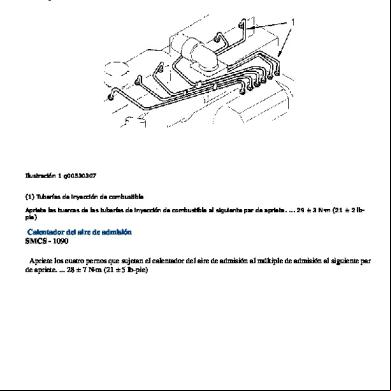
Especificaciones+de+motor+3066(1) 5t40g
December 2019 49
Calibracion De Valvulas Motor 3066 Caterpillar 71374
December 2022 0
Moresa-torques Y Medidas Motor 3u3n20
December 2019 84More Documents from "David Ohara" s265m
Torques Motor 3066 2t31c
December 2019 196
6g3p1u
October 2019 45
6g3p1u
November 2019 54
6g3p1u
December 2019 31
Planilha Do Holder Beta 04.12.2018 3l4v6y
October 2022 0