Star Delta Diagram 64469
This document was ed by and they confirmed that they have the permission to share it. If you are author or own the copyright of this book, please report to us by using this report form. Report 2z6p3t
Overview 5o1f4z
& View Star Delta Diagram as PDF for free.
More details 6z3438
- Words: 362
- Pages: 2
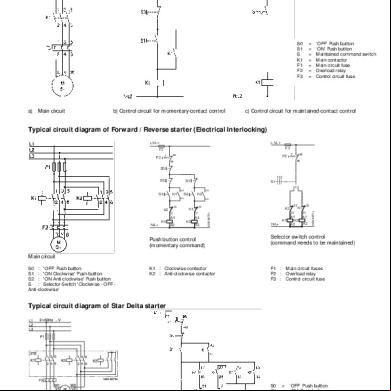
Typical circuit diagram of Direct On Line starter
S0 S1 S K1 F1 F2 F3
a) Main circuit
b) Control circuit for momentary- control
= = = = = = =
‘OFF’ Push button ‘ON’ Push button Maintained command switch Main or Main circuit fuse Overload relay Control circuit fuse
c) Control circuit for maintained- control
Typical circuit diagram of Forward / Reverse starter (Electrical Interlocking) L1/L+
L1/L+
F3
F3 95
F2
95
F2
96
96
S0
53 54
K2
N/L
K1
22
S2
K2
A2
53 54
K1
21
A1
S
K2
22 21
A1 A2
K2 NSK-6970c
K1
S1
10 2
S1
Push button control (momentary command)
N/L
K1
22
K1
22
21
21
A1 K2 A2
A1 A2
NSK-6971c
S2
Selector switch control (command needs to be maintained)
Main circuit S0 : 'OFF' Push button S1 : 'ON Clockwise' Push button S2 : 'ON Anti-clockwise' Push button S : Selector Switch 'Clockwise - OFF Anti-clockwise'
K1 : Clockwise or K2 : Anti-clockwise or
F1 : Main circuit fuses F2 : Overload relay F3 : Control circuit fuse
Typical circuit diagram of Star Delta starter
Main circuit
Control circuit for push button control (momentary command)
S0 S1 K1 K2 K3 K4 F2 F1 F3
= = = = = = = = =
‘OFF’ Push button ‘ON’ Push button Line or Star or Delta or Star delta timer (7PU60 20) Overload relay Backup fuse Control circuit fuse
Typical circuit diagram for Auto Transformer starter
S0 S1 K1 K2 K3 K5 K4 F1 F2 F3
b) Auxiliary circuit for momentary- control
a) Main Circuit
Internal connection diagram for DC coil circuits
K1 : Sizes 3 to 6, 3TF46 to 3TF51
K1 : Sizes 8 to 12 3TF52 to 3TF56 K2 : 3TF30 10 OB.. for 3TF54/55 3TF32 00-OB.. for 3TF56
The control circuits indicated by dotted lines are to be wired by customer.
K1 : Size 12 3TF57 K2 : 3TC44 17 4A..
= ‘OFF’ Push button = ‘ON’ Push button = Star or = Transformer or = Main or = or relay (2NO + 2NC) = Time relay (7PU6020) = Main circuit fuses = Overload relay = Control circuit fuse
Related Documents c2h70
Star Delta Diagram 64469
October 2019 63
Rangkaian Diagram Garis Star Delta 23e16
May 2020 4
Star Delta 4h3u3d
September 2020 0
Typical Circuit Diagram Of Star Delta Starter 1z534v
December 2019 99
Star Delta Connection Diagram And Working Principle.docx 5e2b5p
November 2019 33