Siemens Mccb 3vt1 Up To 160 Amp 33k1o
This document was ed by and they confirmed that they have the permission to share it. If you are author or own the copyright of this book, please report to us by using this report form. Report 2z6p3t
Overview 5o1f4z
& View Siemens Mccb 3vt1 Up To 160 Amp as PDF for free.
More details 6z3438
- Words: 11,861
- Pages: 37
© Siemens AG 2011
3VT1 Molded Case Circuit Breakers up to 160 A Catalog ■ Overview Versions and accessories Connecting sets
3
4 5
2
6
7
Circuit breaker
9
10
11
1
8 12
13
14 NSO0_00258a
1
General data
Rotary operating mechanism
15 17
18
19
20
16
23
22
21 1 3VT circuit breaker 2 Circular conductor terminal 3 Front connection 4 Rear connection 5 Auxiliary conductor terminal 6 Front connecting bus with increased
pole spacing 7 Insulating barriers 8 Lateral rotary operating mechanism 9 Shunt trip unit
1/2
Siemens LV 36 · 2011
24
27
26
25
10 Undervoltage trip unit 11 Adapter to install on 35 mm DIN rail 12 Lockingtype lever 13 Signal switch 14 Auxiliary switch 15 Mechanical parallel switching 16 Mechanical interlocking 17 Front manual operating mechanism 18 Front manual operating mechanism
19 Lateral manual operating mechanism (right) 20 Lateral manual operating mechanism (left) 21 Non lockable knob 22 Coupling driver 23 Telescopic extension shaft 24 Lockable knob 25 Lockable knob 26 Coupling driver 27 Extension shaft
© Siemens AG 2011
3VT1 Molded Case Circuit Breakers up to 160 A Catalog Circuit breakers · Switch disconnectors
■ Overview Circuit breaker
Switch disconnector
Circuit breaker, 3-/4-pole versions
Switch disconnector, 3-/4-pole versions
The 3- or 4-pole versions of the circuit breakers include: • 2 connecting sets for connecting Cu/Al cables1) with crosssections of 2.5 ... 95 mm2 (these terminals are connected to the circuit breaker) • insulating barriers • set of two mounting bolts (M3 x 30)
The 3- or 4-pole versions of the switch disconnectors include: • 2 connecting sets for connecting Cu/Al cables1) with crosssections of 2.5 ... 95 mm2 (these terminals are connected to the switch disconnector) • insulating barriers • set of two mounting bolts (M3 x 30)
■ Selection and ordering data Rated current In
Current setting of the inverse-time delayed overload trip unit „L“ Ir
A
A
DT
Order No.
PS*
Weight per PU approx. kg
Circuit breakers with tripping characteristic L 2) TM3), LI function, 3-pole • with permanently fixed thermal overload trip unit, fixed short-circuit trip unit 40
160
B
3VT1 704-2DA36-0AA0
1 unit
1.043
50
200
B
3VT1 705-2DA36-0AA0
1 unit
1.043
63
252
B
3VT1 706-2DA36-0AA0
1 unit
1.062
80
320
B
3VT1 708-2DA36-0AA0
1 unit
1.062
100
400
B
3VT1 710-2DA36-0AA0
1 unit
1.047
125
500
B
3VT1 712-2DA36-0AA0
1 unit
1.047
160
640
B
3VT1 716-2DA36-0AA0
1 unit
1.074
TM, LI function, 3-pole + N, for unprotected N-conductor • with permanently fixed thermal overload trip unit, fixed short-circuit trip unit 40
160
B
3VT1 704-2EA46-0AA0
1 unit
1.336
50
200
B
3VT1 705-2EA46-0AA0
1 unit
1.336
63
252
B
3VT1 706-2EA46-0AA0
1 unit
1.336
80
320
B
3VT1 708-2EA46-0AA0
1 unit
1.336
100
400
B
3VT1 710-2EA46-0AA0
1 unit
1.336
125
500
B
3VT1 712-2EA46-0AA0
1 unit
1.336
160
640
B
3VT1 716-2EA46-0AA0
1 unit
1.336
TM, LI function, 4-pole, for protected N-conductor • with permanently fixed overload trip unit, fixed short-circuit trip unit
1)
40
160
B
3VT1 704-2EH46-0AA0
1 unit
1.336
50
200
B
3VT1 705-2EH46-0AA0
1 unit
1.336
63
252
B
3VT1 706-2EH46-0AA0
1 unit
1.336
80
320
B
3VT1 708-2EH46-0AA0
1 unit
1.336
100
400
B
3VT1 710-2EH46-0AA0
1 unit
1.336
125
500
B
3VT1 712-2EH46-0AA0
1 unit
1.336
160
640
B
3VT1 716-2EH46-0AA0
1 unit
1.336
For other connection methods, use connecting sets, see page 1/10
2)
See pages 1/16 (3-pole) and 1/21 (4-pole)
3)
Thermal-magnetic trip unit
* You can order this quantity or a multiple thereof. Siemens LV 36 · 2011
1/3
1
© Siemens AG 2011
3VT1 Molded Case Circuit Breakers up to 160 A Catalog
1
Circuit breakers · Switch disconnectors Rated current In
Current setting of the inverse-time delayed overload trip unit „L“ Ir
A
A
DT
Order No.
PS*
Weight per PU approx. kg
Circuit breakers with tripping characteristic D 1) TM, LI function 3-pole • with adjustable thermal overload trip unit, adjustable short-circuit trip unit 16
160 ... 240
B
3VT1 701-2DC36-0AA0
1 unit
1.048
20
200 ... 300
B
3VT1 702-2DC36-0AA0
1 unit
1.048
25
250 ... 375
B
3VT1 792-2DC36-0AA0
1 unit
1.043
32
160 ... 320
B
3VT1 703-2DC36-0AA0
1 unit
1.047
40
200 ... 400
B
3VT1 704-2DC36-0AA0
1 unit
1.043
50
250 ... 500
B
3VT1 705-2DC36-0AA0
1 unit
1.043
63
315 ... 630
B
3VT1 706-2DC36-0AA0
1 unit
1.062
80
400 ... 800
B
3VT1 708-2DC36-0AA0
1 unit
1.062
100
500 ... 1000
B
3VT1 710-2DC36-0AA0
1 unit
1.047
125
625 ... 1250
B
3VT1 712-2DC36-0AA0
1 unit
1.047
160
800 ... 1600
B
3VT1 716-2DC36-0AA0
1 unit
1.074
TM, LI function 3-pole +N, for unprotected N-conductor • with adjustable thermal overload trip unit, adjustable short-circuit trip unit 16
160 ... 240
B
3VT1 701-2EC46-0AA0
1 unit
1.336
20
200 ... 300
B
3VT1 702-2EC46-0AA0
1 unit
1.336
25
250 ... 375
B
3VT1 792-2EC46-0AA0
1 unit
1.336
32
160 ... 320
B
3VT1 703-2EC46-0AA0
1 unit
1.336
40
200 ... 400
B
3VT1 704-2EC46-0AA0
1 unit
1.336
50
250 ... 500
B
3VT1 705-2EC46-0AA0
1 unit
1.336
63
315 ... 630
B
3VT1 706-2EC46-0AA0
1 unit
1.336
80
400 ... 800
B
3VT1 708-2EC46-0AA0
1 unit
1.336
100
500 ... 1000
B
3VT1 710-2EC46-0AA0
1 unit
1.336
125
625 ... 1250
B
3VT1 712-2EC46-0AA0
1 unit
1.336
160
800 ... 1600
B
3VT1 716-2EC46-0AA0
1 unit
1.336
TM, LIN function 4 pole, for protected N-conductor • with adjustable thermal overload trip unit, adjustable short-circuit trip unit
1)
16
160 ... 240
B
3VT1 701-2EJ46-0AA0
1 unit
1.336
20
200 ... 300
B
3VT1 702-2EJ46-0AA0
1 unit
1.336
25
250 ... 375
B
3VT1 792-2EJ46-0AA0
1 unit
1.336
32
160 ... 320
B
3VT1 703-2EJ46-0AA0
1 unit
1.336
40
200 ... 400
B
3VT1 704-2EJ46-0AA0
1 unit
1.336
50
250 ... 500
B
3VT1 705-2EJ46-0AA0
1 unit
1.336
63
315 ... 630
B
3VT1 706-2EJ46-0AA0
1 unit
1.336
80
400 ... 800
B
3VT1 708-2EJ46-0AA0
1 unit
1.380
100
500 ... 1000
B
3VT1 710-2EJ46-0AA0
1 unit
1.336
125
625 ... 1250
B
3VT1 712-2EJ46-0AA0
1 unit
1.336
160
800 ... 1600
B
3VT1 716-2EJ46-0AA0
1 unit
1.336
See pages 1/16 (3-pole) and 1/21 (4-pole)
* You can order this quantity or a multiple thereof.
1/4
Siemens LV 36 · 2011
© Siemens AG 2011
3VT1 Molded Case Circuit Breakers up to 160 A Catalog Circuit breakers · Switch disconnectors Rated current In
Current setting of the short-circuit trip unit „I“ Ii
A
A
DT
Order No.
PS*
Weight per PU approx. kg
Circuit breakers, for short-circuit protection only (tripping characteristic N 1),) TM, I function, 3-pole • without overload trip unit, with adjustable short-circuit trip unit 32
160 ... 320
B
3VT1 703-2DB36-0AA0
1 unit
1.043
40
200 ... 400
B
3VT1 704-2DB36-0AA0
1 unit
1.043
50
250 ... 500
B
3VT1 705-2DB36-0AA0
1 unit
1.048
63
315 ... 630
B
3VT1 706-2DB36-0AA0
1 unit
1.048
80
400 ... 800
B
3VT1 708-2DB36-0AA0
1 unit
1.048
100
500 ... 1000
B
3VT1 710-2DB36-0AA0
1 unit
1.050
125
625 ... 1250
B
3VT1 712-2DB36-0AA0
1 unit
1.059
160
800 ... 1600
B
3VT1 716-2DB36-0AA0
1 unit
1.048
TM, I function, 3-pole +N, for unprotected conductors • without overload trip unit, with adjustable short-circuit trip unit 32
160 ... 320
B
3VT1 703-2EB46-0AA0
1 unit
1.336
40
200 ... 400
B
3VT1 704-2EB46-0AA0
1 unit
1.336
50
250 ... 500
B
3VT1 705-2EB46-0AA0
1 unit
1.336
63
315 ... 630
B
3VT1 706-2EB46-0AA0
1 unit
1.336
80
400 ... 800
B
3VT1 708-2EB46-0AA0
1 unit
1.336
100
500 ... 1000
B
3VT1 710-2EB46-0AA0
1 unit
1.336
125
625 ... 1250
B
3VT1 712-2EB46-0AA0
1 unit
1.336
160
800 ... 1600
B
3VT1 716-2EB46-0AA0
1 unit
1.336
Circuit breakers with tripping characteristic M 2), for starter combinations TM, LI function, 3-pole • with adjustable thermal overload trip units, fixed short-circuit trip units 16
12.5 ... 16
B
3VT1 701-2DM36-0AA0
1 unit
1.048
20
16 ... 20
B
3VT1 702-2DM36-0AA0
1 unit
1.048
25
20 ... 25
B
3VT1 792-2DM36-0AA0
1 unit
1.043
32
25 ... 32
B
3VT1 703-2DM36-0AA0
1 unit
1.043
40
32 ... 40
B
3VT1 704-2DM36-0AA0
1 unit
1.043
50
40 ... 50
B
3VT1 705-2DM36-0AA0
1 unit
1.043
63
50 ... 63
B
3VT1 706-2DM36-0AA0
1 unit
1.062
80
63 ... 80
B
3VT1 708-2DM36-0AA0
1 unit
1.059
100
80 ... 100
B
3VT1 710-2DM36-0AA0
1 unit
1.047
Switch disconnectors Switch disconnector, without overload protection, without short circuit protection 160
3-pole
B
3VT1 716-2DE36-0AA0
1 unit
1.043
160
4-pole
B
3VT1 716-2EE46-0AA0
1 unit
1.336
1)
See page 1/16 (3-pole)
2)
See pages 1/16 and 1/20
* You can order this quantity or a multiple thereof. Siemens LV 36 · 2011
1/5
1
© Siemens AG 2011
3VT1 Molded Case Circuit Breakers up to 160 A Catalog - Accessories and Components
1
Auxiliary switches · Auxiliary trip units
■ Overview Circuit breakers can be equipped with • auxiliary switches, • alarm switches, • shunt trip units, • undervoltage trip units.
Shunt trip units can trip the circuit breaker from a remote location. A control supply voltage is required. An undervoltage trip unit trips the circuit breaker automatically when the circuit voltage drops below 70 % Ue. The undervoltage trip unit protects motors and other equipment in case of undervoltage. A control supply voltage is required.
■ Selection and ordering data Rated control supply voltage Us
DT Order No.
PS*
Weight per PU approx. kg
AC 50/60 Hz or DC
Auxiliary switches and alarm switches Auxiliary switches for signalling the state of the main s • AC/DC 60 ... 250 V
B
3VT9 100-2AB10
1 unit
0.010
• AC/DC 5 ... 60 V
B
3VT9 100-2AB20
1 unit
0.010
• AC/DC 60 ... 250 V
B
3VT9 100-2AH10
1 unit
0.010
• AC/DC 5 ... 60 V
B
3VT9 100-2AH20
1 unit
0.010
Alarm switches for signalling the tripping of the circuit breaker by an trip unit
Shunt trip units Shunt trip units can trip the circuit breaker from a remote location. • AC/DC 24, 48 V
B
3VT9 100-1SC00
1 unit
0.050
• AC 110, 230 V/DC 110, 220 V
B
3VT9 100-1SD00
1 unit
0.050
• AC 230, 400 V/DC 220 V
B
3VT9 100-1SE00
1 unit
0.050
Undervoltage trip units Undervoltage trip units trip the circuit breaker automatically when the circuit voltage drops below 70 % Ue • AC 24, 48 V
B
3VT9 100-1UC00
1 unit
0.050
• AC 110, 230 V
B
3VT9 100-1UD00
1 unit
0.050
• AC 230, 400 V
B
3VT9 100-1UE00
1 unit
0.050
• DC 24, 48 V
B
3VT9 100-1UU00
1 unit
0.050
• DC 110, 220 V
B
3VT9 100-1UV00
1 unit
0.050
* You can order this quantity or a multiple thereof.
1/6
Siemens LV 36 · 2011
© Siemens AG 2011
3VT1 Molded Case Circuit Breakers up to 160 A Catalog - Accessories and Components Manual/motorized operating mechanisms
■ Overview Rotary operating mechanisms The rotary operating mechanism must be combined from the following parts: • For rotary operation of the circuit breaker: - 3VT9 100-3HE../HF.. knob • For operation through the switchgear cabinet door: - 3VT9 100-3HE../HF.. knob - 3VT9 100-3HG../HH.. coupling driver - 3VT9 100-3HJ.. extension shaft,
• For operating through side of switchgear cabinet (lateral operation): - 3VT9 100-3HE../HF.. knob - 3VT9 100-3HG../HH.. coupling driver - 3VT9 100-3HJ.. extension shaft Mechanical interlocking and parallel switching • The mechanical interlock must be combined from the following parts: - 2 x 3VT9 200-3HA/HB.. rotary operating mechanisms (cannot be used with lateral operation) - 2 x 3VT9 200-3HE/HF.. knobs (standard) or 1 x 3VT9 200-3HE/HF.. knob (parallel switching)
■ Selection and ordering data Version
Color
DT Order No.
PS*
Weight per PU approx. kg
Rotary operating mechanisms Rotary operating mechanism • not lockable
gray
B
3VT9 100-3HA10
1 unit
0.079
• lockable with padlock
gray
B
3VT9 100-3HA20
1 unit
0.079
• lockable with padlock
yellow
B
3VT9 100-3HB20
1 unit
0.079
• for lateral operation, mounted on the left side, not lockable
gray
B
3VT9 100-3HC10
1 unit
0.137
• for lateral operation, mounted on the right side, not lockable
gray
B
3VT9 100-3HD10
1 unit
0.137
Knob • not lockable
black
B
3VT9 100-3HE10
1 unit
0.019
• lockable with padlock
black
B
3VT9 100-3HE20
1 unit
0.019
• lockable with padlock
red
B
3VT9 100-3HF20
1 unit
0.019
Coupling driver for door-coupling operating mechanism Additionally requires 3VT9 100-3HE10 or 3VT9 100-3HE20 black knob • degree of protection IP40
black
B
3VT9 100-3HG10
1 unit
0.042
• degree of protection IP66
black
B
3VT9 100-3HG20
1 unit
0.042
Additionally requires 3VT9 100-3HF20 red knob • degree of protection IP40
yellow
B
3VT9 100-3HH10
1 unit
0.042
• degree of protection IP66
yellow
B
3VT9 100-3HH20
1 unit
0.042
• length 350 mm, can be shortened
B
3VT9 100-3HJ10
1 unit
0.113
• length 199 ... 352 mm, telescopic
B
3VT9 100-3HJ20
1 unit
0.092
Extension shaft
* You can order this quantity or a multiple thereof. Siemens LV 36 · 2011
1/7
1
© Siemens AG 2011
3VT1 Molded Case Circuit Breakers up to 160 A Catalog - Accessories and Components
1
Manual/motorized operating mechanisms Version
Color
DT Order No.
PS*
Weight per PU approx. kg
Mechanical interlocks The mechanical interlocks additionally require the following parts: • 2 x 3VT9 100-3HA../HB.. rotary operating mechanisms • 1 or 2 x 3VT9 100-3HE/HF.. knobs Mechanical interlock
B
3VT9 100-8LA00
1 unit
0.089
Mechanical interlock for parallel switching
B
3VT9 100-8LB00
1 unit
0.109
Rated control supply voltage Us
DT Order No.
PS*
Weight per PU approx. kg
AC 50/60 Hz or DC
Motorized operating mechanism Laterally mounted motorized operating mechanism For a detailed description see page 1/30. • AC/DC 24 V
B
3VT9 100-3MA00
1 unit
0.900
• AC/DC 48 V
B
3VT9 100-3MB00
1 unit
0.900
• AC/DC 110 V
B
3VT9 100-3MD00
1 unit
0.900
• AC 230 V/DC 220 V
B
3VT9 100-3ME00
1 unit
0.900
* You can order this quantity or a multiple thereof.
1/8
Siemens LV 36 · 2011
© Siemens AG 2011
3VT1 Molded Case Circuit Breakers up to 160 A Catalog - Accessories and Components
N
Residual current devices
■ Selection and ordering data Circuit breakers for system protection, only for TM1), starters, disconnectors Rated current IN Residual currents I, adjustable
Delay time td, adjustable
Rated operaDT Order No. tional voltage Ue
PS*
Weight per PU approx.
A
A
s
V
0.030
instantaneous
80 ... 440
C
3VT9 116-5GA40
1 unit
1.300
0.100
0.1
0.300
0.2
0.500
0.3
1.000
0.5
3.000
1
0.300
instantaneous
80 ... 440
C
3VT9 116-5GB40
1 unit
1.300
3-pole
3VT9 115-5GY31
1 unit
4-pole
3VT9 115-5GY41
1 unit
3-pole
3VT9 115-5GY32
1 unit
4-pole
3VT9 115-5GY42
1 unit
kg
RCD modules 4-pole 160
4-pole 160
Accessories for RCD modules Connection set, short
Connection set, long
1) Thermal-magnetic
* You can order this quantity or a multiple thereof. Siemens LV 36 · 2011
1/9
1
© Siemens AG 2011
3VT1 Molded Case Circuit Breakers up to 160 A Catalog - Accessories and Components
1
Connecting accessories
■ Selection and ordering data Version
Conductor Type of cross-sections S connection
DT Order No.
mm2
PS*
Weight per PU approx . kg
Terminals for fixed-mounted circuit breakers Connecting set for 3-pole version Terminals for front connection
--
Cu/Al busbars, cable lugs
B
3VT9 100-4TA30
1 unit 0.045
2 x 25 ... 120
Cu/Al cable
B
3VT9 100-4TF30
1 unit 0.180
Cu/Al busbars, cable lugs
B
3VT9 100-4RC30
1 unit 0.320
1 set = 3 units Terminals for circular conductors Set includes a terminal cover, degree of protection IP20
Terminals for rear connection 1 set = 3 units
Auxiliary conductor terminals
1.5 ... 2.5; 4 ... 6
Cu flexible conductors
B
3VT9 100-4TN30
1 unit 0.010
Front connection bars
1.5 ... 2.5; 4 ... 6
Cu/Al busbars, cable lugs
B
3VT9 100-4ED30
1 unit 0.103
--
Cu/Al busbars, cable lugs
B
3VT9 100-4TA00
1 unit 0.015
2 x 25 ... 120
Cu/Al cable
B
3VT9 100-4TF40
1 unit 0.250
Cu/Al-busbars, B cable lugs
3VT9 100-4RC00
1 unit 0.080
Cu flexible conductor
3VT9 100-4TN00
1 unit 0.010
Terminals for 4-pole version Terminal for front connection 1 set = 1 unit For 4th pole (to be used with 3VT9 100-4TA30 connecting set) Terminals for circular conductors Set includes a terminal cover, degree of protection IP20
Terminal for rear connection 1 set = 1 unit For 4th pole (to be used with 3VT9 100-4RC30 connecting set) Auxiliary conductor terminals For 4th pole (to be used with 3VT9 100-4TN30 connecting set)
1,5 ... 2,5; 4 ... 6
B
* You can order this quantity or a multiple thereof.
1/10
Siemens LV 36 · 2011
© Siemens AG 2011
3VT1 Molded Case Circuit Breakers up to 160 A Catalog - Accessories and Components Mounting accessories
■ Selection and ordering data Version
Conductor cross-sections S
Connection
DT Order No.
PS*
mm2
Weight per PU approx. kg
Accessories 3-pole version Insulating barriers for circuit breakers
B
3VT9 100-8CE30
1 unit
0.030
B
3VT9 100-8CA30
1 unit
0.050
B
3 VT9 100-3HL00
1 unit
0.005
B
3VT9 100-8CE00
1 unit
0.020
B
3VT9 100-8CA40
1 unit
0.080
B
3VT9 100-3MF00
1 unit
0.100
B
3VT9 100-4-poleP30
1 unit
0.050
Included in the scope of supply of the circuit breaker or switch disconnector In case of feed-in from below (power supply connected to terminals 2, 4 , 6), it is necessary to install these barriers on the bottom side For more information, see page 1/36. Terminal protection cover, degree of protection IP20 Increases degree of protection of the connection point to degree of protection IP20, e.g. when used with cable lugs.
Locking devices for toggle levers • Enables locking of circuit breaker or switch disconnector in „switched off manually“ position • Locking is possible using a padlock with a shank diameter of up to 4 mm.
4-pole version Insulating barrier for circuit breakers • Included in the scope of supply of circuit breaker or switch disconnector • In case of feed-in from below, (power supply connected to terminals 2, 4, 6, N), it is necessary to install these barriers on the bottom side For more information, see page 1/37.
Terminal cover, degree of protection IP20 Increases the degree of protection of the connecting point to degree of protection IP20, e.g. when used with cable lugs
Extension cable for motorized operating mechanism
Mounting adapter 3-pole version For mounting on a 35 mm standard DIN mounting rail For dimensions, see page 1/45.
* You can order this quantity or a multiple thereof. Siemens LV 36 · 2011
1/11
1
© Siemens AG 2011
3VT1 Molded Case Circuit Breakers up to 160 A Technical Information
1
Circuit breakers · Switch disconnectors
■ Design Recommended cross-section of cables, busbars and flexibars
Installation and connection Main circuit • The main circuit is connected with Cu or AI busbars, cables, and possibly cables with cable lugs. • For further connecting options, connecting sets can be used (see page 1/10). • Generally, conductors from the power supply are connected to input terminals 1, 3, 5, (N) and conductors from the load to terminals 2, 4, 6, (N). It is possible to reverse the current flow inside the unit (i. e. infeed from below) without reducing the rated short-circuit ultimate breaking capacity Icu. • In case of infeed from below, the units must additionally be fitted with 3VT9 100-8CE30 insulating barriers on the side of terminals 2, 4, 6 (see pages 1/36 and 1/37). • We recommend painting the connection busbars. • Input and output connectors/busbars must be mechanically reinforced to avoid transferring electrodynamic forces to the circuit breaker during short-circuiting. • The power circuit must be connected in such a way that the deionizing space of the circuit breaker/switch disconnector is not obstructed (see pages 1/36 and 1/37).
Rated Conductor cross-section S current In A
Busbars W x H
Cu
AI
Cu
AI
mm2
mm2
mm
mm
16
2,5
--
--
--
20
2,5
--
--
--
25
4
--
--
--
32
6
--
--
--
40
10
--
--
--
50
10
16
--
--
63
16
25
--
--
80
25
35
--
--
100
35
50
16 x 2; 12 x 3
16 x 4; 12 x 4
125
50
95
16 x 4; 12 x 4
16 x 5; 12 x 6
160
70
120
16 x 5; 12 x 6
--
Auxiliary circuits Switches, shunt trip units or undervoltage trip units are connected to the terminals of the circuit breaker/switch disconnector using flexible Cu conductors with cross-section 0.5 ... 1 mm2.
Conductor cross-sections of main terminals Order No.
Maximum Maximum permissible conductor cross-sections S permitted Cable type current Imax Sector-shaped Sector-shaped con- Round conductor, conductor, stranded ductor, solid stranded
Round conductor, solid
A
mm2
mm2
mm2
mm2
3VT9 100-4TF30
160
2 x 25 ... 120
2 x 25 ... 120
2 x 25 ... 120
2 x 25 ... 120
3VT9 100-4TA30
160
3VT9 100-4RC30
160
Max. width of busbars and cable lugs
Dimensional drawings
mm
See page
3-pole
3VT9 100-4TN30 3VT9 100-4ED30
10/16
1/38 16
1,5 ... 2,5/4 ... 6
160
16
1/39
--
--
30
1/39
4-pole 3VT9 100-4TF40
160
3VT9 100-4TA00
160
3VT9 100-4RC00
160
3VT9 100-4TN00
1/12
10/16
2 x 25 ... 120
2 x 25 ... 120
2 x 25 ... 120
2 x 25 ... 120
1/43 16 16
1,5 ... 2,5/4 ... 6
Siemens LV 36 · 2011
1/43
© Siemens AG 2011
3VT1 Molded Case Circuit Breakers up to 160 A Technical Information Circuit breakers · Switch disconnectors
■ Technical specifications Order No.
3VT1 7..-2..36-0AA0 3VT1 716-2DE36-0AA0 3VT1 7..-2..46-0AA0
Description
Circuit breakers
Number of poles
3
Standards
EN 60 947-2, IEC 947-2
EN 60 947-3,IEC 947-3 EN 60 947-2, IEC 947-2
Switch disconnectors Circuit breakers 3)
3VT1 716-2EE460AA0 Switch disconnectors
4 EN 60 947-3,IEC 947-3
Approval marks Rated current In
A
16 ... 1602)
--
16 ... 1602)
--
Rated uninterrupted current Iu
A
16 ... 1602)
160
16 ... 1602)
160
Rated operational current Ie
A
--
160
--
160
Rated operational voltage Ue
V
max. AC 690 max. DC 250
Rated frequency fn
Hz
50/60
Rated impulse withstand voltage Uimp
kV
8
Rated insulation voltage Ui
V
690
max. AC 690 max. DC 440
Utilization category • selectivity AC 690 V
A
A
--
• switching mode
AC-3 (16 ... 100 A) AC-23 A AC-2 (100 ... 160 A)
AC-3 (16 ... 100 A) AC-2 (100 ... 160 A)
DC-22 A AC-23 A
Rated short-time withstand current Icw /t
--
2 kA/ 1 s
--
2 kA/1 s
Rated ultimate short-circuit breaking capacity (rms value)1) Icu/Ue
6 kA/AC 690 V 12 kA/AC 500 V 25 kA/AC 415 V 40 kA/AC 230 V
--
13 kA/DC 440V (τ = max. 5 ms) 6 kA/AC 690 V 12 kA/AC 500 V 25 kA/AC 415 V 40 kA/AC 230 V
Off-time at Icu
ms
--
7
--
7
Rated service short-circuit breaking capacity (rms value) Ics/Ue
3 kA/AC 690 V 6 kA/AC 500 V 13 kA/AC 415 V 20 kA/AC 230 V
--
13 kA/DC 440V (τ = max. 5 ms) 3 kA/AC 690 V 6 kA/AC 500 V 13 kA/AC 415 V 20 kA/AC 230 V
Rated short-circuit making capacity (peak value) Icm/Ue
52 kA/AC 415 V
2.8 kA/AC 415 V
52 kA/AC 415 V
Losses per pole at In = 160 A
W
see table page 1/14 15
Mechanical endurance
cycles
20 000
Electrical endurance (Ue = AC 415 V )
cycles
6 000
Frequency of switching
cycles/hr 120
Operating force
N
55
Front-side device protection
IP40
Terminal protection
IP20
--
2.8 kA/AC 415 V
65
Operating conditions Reference ambient temperature
°C
Ambient temperature range
°C
Working environment
40 -40 ... +55 dry and tropical climate
Degree of pollution
3
Max. elevation
m
2000
Seismic resistance
m/s2
3 g at 8 ... 50 Hz
Design modifications Front/rear connection
✓/✓
Plug-in version
--
Withdrawable version
--
Accessories Switches - auxiliary/relative/signal/leading
✓/–/✓/–
Shunt trip unit/with alarm switch
✓/✓
Undervoltage trip unit/with leading switch/with alarm switch
✓/–/✓
Front hand drive/lateral drive right/left
✓/✓/✓
Mechanical interlocking to the manual drive by Bowden wire
--/--
--/--
Motor. oper. mechanism/with oper. counter
+/+
+/+
Locking-type lever
✓
✓ available, -- unavailable, + in preparation
1)
When reversing the circuit breaker connection (power supply connected to terminals 2, 4, 6, (N) output to terminals 1, 3, 5, (N)), Icu does not change.
2)
Ranges of rated currents vary according to characteristics, see page 1/17.
3)
Permissible load of N pole is 100%.
Siemens LV 36 · 2011
1/13
1
© Siemens AG 2011
3VT1 Molded Case Circuit Breakers up to 160 A Technical Information ■ Schematics Circuit breakers with accessories 3-pole version Main circuit
Switches auxiliary
1.2 1.4 1.2 1.4
4.2 4.4
5.2 5.4
5
auxiliary
acc.c. no. 1
acc.c. no. 5 acc.c. no. 4
Explanations
3.3VT9 100-2AB10
2.3VT9 100-2AB10
1.3VT9 100-2AB10
or
3.1
6
2.1
1.3VT9 100-2AH10
4
1.1
4.1
2
acc.c. no. 2 acc.c. no. 3
NSO0 00523
acc.c. no. 6
V
I> 5.1
B1
3VT9 100-1S.00
6.2 6.4 6.1 6.3VT9 100-2AB10
10.Y2
A2
acc.comp. no. 10
3
Q
U
or
alarm or aux.
1
TEST
B2
U<
J
10.Y1
A1
3VT9 100-1U.00
10.Y1
auxiliary
3.2 3.4
Auxiliary starters
2.2 2.4
or
1.1
Switches
10.Y2
1
Circuit breakers · Switch disconnectors
TEST pushbutton
J
3VT1 circuit breaker
Q
main s
V
trip-free mechanism
TEST
TEST pushbutton
3VT9 100-1U.00
undervoltage trip unit
3VT9 100-1S.00
shunt trip unit
acc. c.
accessory compartment
acc. comp.
accessory compartment
Pressing the TEST pushbutton switches the circuit breaker/switch disconnector off and actuates the auxiliary switches.
Power losses (per pole) Rated current In
Power loss P per pole of circuit breaker at maximum current
A
W
16
4
20
4
25
4
32
4
Operator
40
4
50
5
Indication of circuit breaker tripping
63
6
80
7
100
10
125
15
160
15
1/14
Siemens LV 36 · 2011
When the circuit breaker was tripped by the overcurrent trip unit, the following symbol is displayed: „ “
© Siemens AG 2011
3VT1 Molded Case Circuit Breakers up to 160 A Technical Information Circuit breakers · Switch disconnectors 4-pole version Switches
3VT9 100-2AB.0
3VT9 100-2AB.0
acc.c. 3
3.1
acc.c. 2
NSO0_00001a
acc.c. no. 1
2.1
or
1.1
1.1
B2
10.Y2
N 2 4 6
3VT9 100-2AB.0
3VT9 100-2AH.0
V
Q
I> A2
2.2 2.4
1.2 1.4 1.2 1.4
A1 3VT9 100-1S.00
TEST pushbutton
T
acc.comp. no. 10
auxiliary
TEST
or
10.Y2
3VT9 100-2AB.0
acc.c. no. 4
U
N 1 3 5
auxiliary
3VT9 100-2AB.0
acc.c. no. 5
4.1
3VT9 100-2AB.0
5.1
3VT9 100-2AB.0
6.1
U<
J acc.c. no. 6
Switches
3.2 3.4
Main circuit
alarm or aux.
10.Y1
auxiliary 4.2 4.4
Auxiliary starters
auxiliary 5.2 5.4
or
auxiliary 6.2 6.4
Switches
acc.c. no. 7
10.Y1
acc.c. no. 8
A1 3VT9 100-1U.00
acc.c. no. 9
7.1
8.1
3VT9 100-2AB.0
3VT9 100-2AB.0 9.1
J
auxiliary 7.2 7.4
auxiliary 8.2 8.4
9.2 9.4
auxiliary
Explanations J
3VT1 circuit breakers
Q
main s
T
thermomagnetic trip unit 3-pole +N (3 poles protected, N-pole unprotected) 4-pole (all four poles protected)
V
trip-free mechanism
TEST
test pushbutton
3VT9 100-1U.00 undervoltage trip unit 3VT9 100-1S.00
shunt trip unit
acc. c.
accessory compartment
acc. comp.
accessory compartment
Siemens LV 36 · 2011
1/15
1
© Siemens AG 2011
3VT1 Molded Case Circuit Breakers up to 160 A Technical Information - Accessories and Components ■ Overview Trip units, 3-pole version
Circuit breakers with characteristic
Trip units are integrated in the circuit breakers.
„L“:
Tripping characteristics Circuit breakers are available with four types of tripping characteristics. They are designated with the letters:
I
L t
„M“ - motor For motor protection 3VT1 circuit breakers with characteristic „M“ have the option of setting a reduced current in a range of approximately 0.75 ... 1 In. The circuit breakers feature In values in a standardized series of currents from 16 A to 100 A (see „Ranges of trip units and their possible setting“). The short-circuit trip unit is fixed at the value of 10 x In. See page 1/20. „N“ - short-circuit trip unit only 3VT1 circuit breakers with characteristic „N“ have a short circuit trip unit only. They feature In values in a standardized series of currents ranging from 32 A to 160 A. The short-circuit trip unit is adjustable. The values are shown in the table on page 1/17.
I
„M“:
Ir
t
I
„D“: I
L
Order numbers The order number of a circuit breaker depends on the rated current and on the tripping characteristics. For example: Motor protection with In = 32 A. The order number is: 3VT1 703-3DM36-0AA0.
I
L
NSO0_00048
„D“ - distribution For protection of lines and transformers 3VT1 circuit breakers with characteristic „D“ have the option of setting to a reduced current in a range of approximately 0.75 ... 1 In. The circuit breakers feature In values in a standardized current range from 16 A to 160 A (see „Ranges of trip units and their possible settings“). The short-circuit trip unit is adjustable. Setting values are shown in the table on page 1/17.
NSO0_00502
„L“ - lines For protection of lines with low starting currents 3VT1 circuit breakers with characteristic „L“ have a pre-set and fixed rated current value. The circuit breakers feature In values in a standardized current range from 40 A to 160 A (see „Ranges of trip units and their possible settings“). Short-circuit trip units are fixed at 4 x In.
Ir
t
Setting of tripping characteristics Ii NSO0_00500
• Time-dependent trip unit (thermal) L (for circuit breakers with characteristics “D” and “M”). The time-dependent trip unit for overload protection Ir (instantaneous) is adjusted in a continuous range using the Ir adjustment dial on the overload trip unit. The Ir adjustment range is 0.75 ... 1 In. • Time-independent trip unit (short-circuit trip unit) I (for circuit breakers with characteristics “D” and “N”). With an time-independent instantaneous trip unit (value of the short circuit current Ii), adjustment is possible within a continuous range. All values are shown in the table on page 1/17.
I
„N“: I
L t
Ii NSO0_00216
1
Trip units
I
1/16
Siemens LV 36 · 2011
© Siemens AG 2011
3VT1 Molded Case Circuit Breakers up to 160 A Technical Information - Accessories and Components Trip units Setting IR and Ii for circuit breakers with characteristic „D“ Adjusting IR
Adjusting Ii
Derating in accordance with ambient temperature Rated current In
Permissible load at
A
+ 55 °C
+ 40 °C
+20 °C
-15 °C
16
15
16
17
19
20
19
20
22
25
25
23
25
28
31
32
29
32
36
41
40
38
40
45
53
50
48
50
56
66
63
57
63
69
83
80
73
80
88
100
100
91
100
105
122
125
110
125
132
145
160
145
160
168
175
Current ranges of trip units and their possible settings at 40 °C Rated current In
3VT1 7..-2DA36-0AA0 Overload protection Ir
Short circuit Overload protection Ii (ins- protection Ir tantaneous)
3VT1 7..-2DC36-0AA0
Short circuit Overload protection Ii (ins- protection Ir tantaneous)
Short circuit Overload protection Ii (ins- protection Ir tantaneous)
Short circuit protection Ii (instantaneous)
A
A
A
A
A
3VT1 7..-2DM36-0AA0
3VT1 7..-2DB36-0AA0
A
A
A
A
16
--
--
12,5 ... 16
160 ... 240
12,5 ... 16
160
--
--
20
--
--
16 ... 20
200 ... 300
16 ... 20
200
--
--
25
--
--
20 ... 25
250 ... 375
20 ... 25
250
--
--
32
--
--
25 ... 32
160 ... 320
25 ... 32
320
--
160 ... 320
40
40
160
32 ... 40
200 ... 400
32 ... 40
400
--
200 ... 400
50
50
200
40 ... 50
250 ... 500
40 ... 50
500
--
250 ... 500
63
63
252
50 ... 63
315 ... 630
50 ... 63
630
--
315 ... 630
80
80
320
63 ... 80
400 ... 800
63 ... 80
800
--
400 ... 800
100
100
400
80 ... 100
500 ... 1000
80 ... 100
1000
--
500 ... 1000
125
125
500
100 ... 125
625 ... 1250
--
--
--
625 ... 1250
160
160
640
125 ... 160
800 ... 1600
--
--
--
800 ... 1600
Siemens LV 36 · 2011
1/17
1
© Siemens AG 2011
3VT1 Molded Case Circuit Breakers up to 160 A Technical Information - Accessories and Components
1
Trip units Characteristic „L“, In = 40, 50, 63, 80, 100, 125, 160 A 1.05 1.30
10000 5000 t [s] 2000
Characteristic „D“, In = 32, 40, 50, 63, 80, 100, 125, 160 A
NSO0_00049
NSO0_00051
1000 500
1000 500 200 100 50
200 100 50
L
L
20
20 10 5
1.05 1.30
10000 5000 t [s] 2000
10 5
In = 40 … 160 A
In = 32 … 160 A
2 1 0.5
2 1 0.5 0.2 0.1
0.2
I
0.05
0.1 0.05
0.02 0.01 0.1
0.02 0.01 0.1
0.2
1
0.5
2
5
10
50
20
I
0.2
1
0.5
2
5
10
x In
Characteristic „D“, In = 16, 20, 25 A
Characteristic „M“, In = 16, 20, 25 A
1.05 1.30
10000 5000 t [s] 2000
NSO0_00050
1000 500 200
10 5
In = 16 … 25 A
In = 16 … 25 A
2 1 0.5
0.2 0.1 0.05
0.2 0.1 0.05
I
0.2
0.5
1
2
5
10
50
20 x In
1/18
L
20
2 1 0.5
0.02 0.01 0.1
NSO0_00052
50
20 10 5
1.00 1.20
10000 5000 t [s] 2000 1000 500 200 100
L
100 50
50
20
x In
Siemens LV 36 · 2011
0.02 0.01 0.1
I
0.2
0.5
1
2
5
10
50
20 x In
© Siemens AG 2011
3VT1 Molded Case Circuit Breakers up to 160 A Technical Information - Accessories and Components Trip units Characteristic „M“, In = 32, 40, 50, 63, 80, 100 A 1.00 1.20
10000 5000 t [s] 2000 1000 500 200 100 50
NSO0_00053
L
20 10 5
In = 32 … 100 A
2 1 0.5 0.2
I
0.1 0.05 0.02 0.01 0.1
0.2
0.5
1
2
5
10
50
20 x In
Characteristic „N“, In = 32, 40, 50, 63, 80, 100, 125, 160 A NSO0_00054
10000 5000 t [s] 2000 1000 500 200 100 50 20 10 5
In = 32 … 160 A
2 1 0.5 0.2 0.1 0.05 0.02 0.01 0.1
I
0.2
0.5
1
2
5
10
50
20 x In
Siemens LV 36 · 2011
1/19
1
© Siemens AG 2011
3VT1 Molded Case Circuit Breakers up to 160 A Technical Information - Accessories and Components
1
Trip units Trip units, with tripping characteristics: class M The tripping time of the 3-pole trip unit of 3VT1 circuit breakers with characteristic M at 7.2 In corresponds to the tripping classes 10A, 10 and 20 according to EN 60947-4-1.
Plate of the trip units with characteristic M
Rated current Order No. In 16 A
3VT1 701-2DM36-0AA0
10A
20 A
3VT1 702-2DM36-0AA0
10A
25 A
3VT1 792-2DM36-0AA0
10A
32 A
3VT1 703-2DM36-0AA0
10
40 A
3VT1 704-2DM36-0AA0
10
50 A
3VT1 705-2DM36-0AA0
20
63 A
3VT1 706-2DM36-0AA0
20
80 A
3VT1 708-2DM36-0AA0
20
100 A
3VT1 710-2DM36-0AA0
20
Rated short-circuit ultimate and service breaking capacity of 3-pole 3VT1 circuit breakers in DC circuits Specifications Order No.
3VT1 7..-2DM36-0AA0
Rated operational voltage Ue
DC 250 V
Rated ultimate short-circuit breaking capacity1) (rms value) Icu/Ue
25 kA/DC 250 V; τ = max. 5 ms
Rated service short-circuit breaking capacity (rms value) Ics/Ue
13 kA/DC 250 V; τ = max. 5 ms
Utilization category (switching mode)
DC-22A
1)
in reverse connection of the circuit breaker (input terminals 2, 4, 6 and output terminals 1, 3, 5), Icu does not change.
Circuit breaker connection for circuits DC 250 V:
1/20
Siemens LV 36 · 2011
Class
© Siemens AG 2011
3VT1 Molded Case Circuit Breakers up to 160 A Technical Information - Accessories and Components Trip units Trip units, 4-pole version
Circuit breakers with characteristic
Trip units are integrated into the 3VT1 circuit breakers.
„L“
It is not possible to deinstall or exchange the trip units. 4-pole circuit breakers are manufactured in the following versions: • 3-pole +N (three poles protected, N-pole unprotected) • 4-pole (all four poles protected)
I
L t
The permissible load of the N-pole is 100% In. Tripping characteristics
„L“ - lines For protection of lines with low starting currents 3VT1 circuit breakers with characteristic „L“ have a fixed value of rated current I (without In control). The circuit breakers feature In values of standard current range 40 ... 160 A, see „Ranges of trip units and their possible setting“. The short-circuit trip unit has a fixed setting to 4 x In. „D“ - distribution For protection of lines and transformers 3VT1 circuit breakers with characteristic „D“ can be set to a reduced current in the range of approx. 0.75 ... 1 In. The circuit breakers feature In values within a standard current range of 16 ... 160 A. Setting values are shown in the table on page 1/22.
NSO0_00502
The circuit breakers are delivered with three types of tripping characteristics, designated by the following letters:
I
„D“
t
„N“ - short-circuit For protection against short circuits only 3VT1 circuit breakers with characteristic „N“ have a short circuit trip unit only. They feature circuit breaker values within a standard current range of 32 ... 160 A. The short circuit trip unit is adjustable. The values are shown in the table on page 1/22.
NSO0_00500
I
„N“
t
Ii NSO0_00216
• Time-dependent trip unit (thermal) L (for circuit breakers with characteristics “D” and “M”). The time-dependent trip unit for overload protection Ir (instantaneous), is adjusted in a continuous range using the Ir adjustment dial on the overload trip unit. The Ir adjustment range is 0.75 ... 1 In. • Time-independent instantaneous trip unit (short-circuit trip unit) I (for circuit breakers with characteristics “D” and “N”). With a time-independent instantaneous trip unit (value of the short circuit current Ii), adjustment is possible within a continuous range. All values are shown in the table on page 1/22.
I
L
For example: Protection of a circuit with In = 40 A. The order number is 3VT1 704-2EC46-0AA0. Setting of tripping characteristics
Ir
Ii
Order numbers The order number of a circuit breaker depends on the rated current and on the tripping characteristics.
I
L
I
Siemens LV 36 · 2011
1/21
1
© Siemens AG 2011
3VT1 Molded Case Circuit Breakers up to 160 A Technical Information - Accessories and Components
1
Trip units Setting IR and Ii for circuit breakers with characteristic „D“ Setting IR
Setting Ii
Derating in accordance with ambient temperature Rated current In
Permissible load at
A
+ 55 °C
+ 40 °C
+20 °C
-15 °C
16
15
16
17
19
20
19
20
22
25
25
23
25
28
31
32
29
32
36
41
40
38
40
45
53
50
48
50
56
66
63
57
63
69
83
80
73
80
88
100
100
91
100
105
122
125
110
125
132
145
160
145
160
168
175
Current ranges of trip units and their possible settings at 40 °C Rated current 3VT1 7..-2EA46-0AA0 3VT1 7..-2EC46-0AA0 3VT1 7..-2EB46-0AA0 In Overload protection Ir Short circuit protection Overload protection Ir Short circuit protection Overload protection Ir Short circuit protection Ii (instantaneous) Ii (instantaneous) Ii (instantaneous) A
A
A
A
A
A
16
-
--
12,5 ... 16
160 ... 240
-
-
20
-
--
16 ... 20
200 ... 300
-
-
25
-
--
20 ... 25
250 ... 375
-
-
32
-
--
25 ... 32
160 ... 320
-
160 ... 320
40
40
160
32 ... 40
200 ... 400
-
200 ... 400
50
50
200
40 ... 50
250 ... 500
-
250 ... 500
63
63
252
50 ... 63
315 ... 630
-
315 ... 630
80
80
320
63 ... 80
400 ... 800
-
400 ... 800
100
100
400
80 ... 100
500 ... 1000
-
500 ... 1000
125
125
500
100 ... 125
625 ... 1250
-
625 ... 1250
160
160
640
125 ... 160
800 ... 1600
-
800 ... 1600
1/22
Siemens LV 36 · 2011
A
© Siemens AG 2011
3VT1 Molded Case Circuit Breakers up to 160 A Technical Information - Accessories and Components Trip units Characteristic „D“, In = 16, 20, 25 A
Characteristic „L“, In = 40, 50, 63, 80, 100, 125, 160 A 1.05 1.30
10000 5000 t [s] 2000
NSO0_00049
1000
1000
500
500
200 100 50
200
L
NSO0_00050
L
100 50 20 10
20 10 5
1.05 1.30
10000 5000 t [s] 2000
5
In = 40 … 160 A
In = 16 … 25 A
2 1 0.5
2 1 0.5
0.05
0.2 0.1 0.05
0.02 0.01 0.1
0.02 0.01 0.1
0.2 0.1
I
0.2
0.5
1
2
5
10
50
20
I
0.2
0.5
1
2
5
10
x In
Characteristic „N“, In = 32, 40, 50, 63, 80, 100, 125, 160 A
NSO0_00051
1000 500 200 100 50
50 20
L
20 10 In = 32 … 160 A
5
2 1 0.5
In = 32 … 160 A
2 1 0.5
0.2 0.1 0.05 0.02 0.01 0.1
1.05 1.30
10000 5000 t [s] 2000
200 100
10 5
Characteristic „D“, In = 32, 40, 50, 63, 80, 100, 125, 160 A
NSO0_00054
10000 5000 t [s] 2000 1000 500
50
20
x In
I
0.2
I
0.1 0.05
0.2
0.5
1
2
5
10
50
20 x In
0.02 0.01 0.1
0.2
0.5
1
2
5
10
50
20 x In
Siemens LV 36 · 2011
1/23
1
© Siemens AG 2011
3VT1 Molded Case Circuit Breakers up to 160 A Technical Information - Accessories and Components
1
Auxiliary switches
■ Overview Auxiliary switches
Location of switches in accessory compartments
Auxiliary and alarm switches
Location of accessory compartments in a 3-pole 3VT1 circuit breaker/switch disconnector.
Function, name and location of switches Order No.
Type
Switch location
Switch function
3VT9 100-2AB10 3VT9 100-2AB20
Auxiliary switch
Accessory compartment 11), 2, 3, 4, 5, 62)
Signals the condition of the main of the circuit breaker/ switch disconnector
3VT9 100-2AH10 3VT9 100-2AH20
Alarm switch
Accessory compartment 11)
Signals whether the circuit breaker was tripped by the trip unit
1)
In accessory compartment 1, a 3VT9 100-2AB10 auxiliary switch and 3VT9 100-2AH10 alarm switch cannot be used simultaneously.
2)
When one of accessory compartments 4, 5 or 6 is already in use for auxiliary switches, a shunt trip unit or undervoltage trip unit cannot be installed additionally.
Location of accessory compartments in a 4-pole 3VT1 circuit breaker/switch disconnector.
When using one of the accessory compartments 4, 5 or 6, neither a shunt trip unit nor an undervoltage trip unit can be installed.
1/24
Siemens LV 36 · 2011
© Siemens AG 2011
3VT1 Molded Case Circuit Breakers up to 160 A Technical Information - Accessories and Components Auxiliary switches
■ Function Switching states (3-pole)
Switching states (4-pole) 1 ... 6
1
10
Switching states of the circuit-breaker
3VT9 100-1S... SP-BC-X...
3VT9 100-1UC/UD/UE.. 3VT9 100-1SC/SD/SE..
3VT9 100-2AH10
3VT9 100-2AB10
Position of the main s
Lever position
Accessory compartment
3VT9 100-2AH10
10
3VT9 100-2AB10
1
Position of the main s
1 ... 9
Switching states of the circuit breaker
Lever position
Accessory compartment
Switched on
1
1
0
0
1
1
Switched on
1
1
0
0
1
1
Switched off manually
0
0
1
0
1
1
Switched off manually
0
0
1
0
1
1
Switched off by the trip unit or INSPECTION button
0
0
1
1
0
1
Switched off by the trip unit or INSPECTION button
0
0
1
1
0
1
Switched off by auxiliary trip unit
0
0
1
0
1
0
Switched off by auxiliary trip unit
0
0
1
0
1
0
Switched off by TEST button
0
0
1
0
1
1
Switched off by TEST button
0
0
1
0
1
1
0 = open, 1 = closed
0 = open, 1 = closed
■ Technical specifications Order No.
3VT9 100-2AB10, 3VT9 100-2AH10
3VT9 100-2AB20, 3VT9 100-2AH20 AC 5 ... 60 V DC 5 ... 60 V
Rated operational voltage Ue
V
AC 60 ... 250 V DC 60 ... 250 V
Rated insulation voltage Ui
V
250 V
Rated impulse withstand voltage Uimp kV
4 kV
Rated frequency fn
50/60 Hz
Hz
Rated operational current Ie/Ue AC-12
6 A/250 V
0.0004 ... 0.1 A/5 ... 60 V
AC-15
5 A/60 V, 3 A/110 V, 1.5 A/230 V
0.0004 ... 0.1 A/5 ... 60 V
DC-12
0.25 A/250 V
0.1 A/5 ... 60 V
DC-13
0.5 A/60 V, 0.2 A/110 V, 0.1 A/250 V 0.0004 ... 0.1 A/5 ... 60 V
Thermal current Ith s arrangement Connector cross-section S Terminal protection (connected switch)
A
6A
0.5 A
001 mm2 0.5 ... 1 IP20
Siemens LV 36 · 2011
1/25
1
© Siemens AG 2011
3VT1 Molded Case Circuit Breakers up to 160 A Technical Information - Accessories and Components ■ Design The order number of the auxiliary trip unit depends on the rated operational voltage
Auxiliary trip units
Undervoltage trip unit
Order No. 3VT9 100-1SC00
AC 110/230 V, DC 110/220 V
3VT9 100-1SD00
AC 230/400 V, DC 220 V
3VT9 100-1SE00
Ue
Order No.
AC/DC 24/48 V
3VT9 100-1UC00
AC 110/230 V, DC 110/220 V
3VT9 100-1UD00
AC 230/400 V, DC 220 V
3VT9 100-1UE00
The specific rated operational voltage of the shunt trip unit is set by jumpers located on the trip unit. The standard setting by the manufacturer is always to the value corresponding to the order number. Schematics L+
N-
One auxiliary trip unit can be installed in accessory compartment 10
Shunt trip unit
NSO0_00056
U< NSO0_00055
10.Y2
U
3VT9 100-1U.0
A1 10.Y1
3VT9 100-1S.0
B1 10.Y1
L+
10.Y2
Location of auxiliary trip unit
A2
Shunt trip unit
Ue AC/DC 24/48 V
B2
1
Auxiliary trip units
N-
Undervoltage trip unit
■ Technical specifications Order No.
3VT9 100-1S.00
Order No.
3VT9 100-1U.00
Rated operational voltage Ue
AC 24/48/110/230/400 V DC 24/48/110/220 V
Rated operational voltage Ue
AC 24/48/110/230/400 V DC 24/48/110/220 V
Rated frequency fn
50/60 Hz
Rated frequency fn
50/60 Hz
Input power at 1.1 Ue
Input power at 1.1 Ue
• AC
2 VA
• AC
2 VA
• DC
2W
• DC
2W
Characteristics
U ≥ 0.7 Ue: circuit breaker must trip
Characteristics
U ≤ 0.35 Ue: circuit breaker can be switched on U ≥ 0.85 Ue: circuit breaker must trip
Time before switching off
15 ms
Time before switching off
15 ms
Continuous load
yes
Continuous load
yes
Connection cross-section S
0,5 ... 1 mm2
Connector cross-section S
0.5 ... 1 mm2
Terminal protection (connected trip unit)
IP20
Terminal protection (connected trip unit)
IP20
Location in accessory compartment no. 10
Location in accessory compartment no. 10
Alarm switch - signals that the circuit breaker was switched off by the shunt trip unit
Alarm switch - signals that the circuit breaker was switched off by the undervoltage trip unit
Rated operational voltage Ue
AC 230 V
Rated operational voltage Ue
AC 230 V
Rated insulation voltage Ui
250 V
Rated insulation voltage Ui
250 V
Rated impulse withstand voltage Uimp
4 kV
Rated impulse withstand voltage Uimp
4 kV
Rated frequency fn
50/60 Hz
Rated frequency fn
50/60 Hz
Rated operational current Ie/Ue
2 A/AC 230 V
Rated operational current Ie/Ue
2 A/AC 230 V
Thermal current Ith
6A
Thermal current Ith
6A
arrangement
01
arrangement
01
1/26
Siemens LV 36 · 2011
© Siemens AG 2011
3VT1 Molded Case Circuit Breakers up to 160 A Technical Information - Accessories and Components Rotary operating mechanisms
■ Design Rotary operating mechanisms The rotary operating mechanism actuates the circuit breakers/switch disconnector when the operator turns the knob, e.g. in order to switch machines on and off. The modular concept of the operating mechanism allows simple mounting on the circuit breaker. Mounting can be done after having removed the accessory compartment cover. An attached drive can be sealed (with sealing wire). The drive and its accessories are ordered separately to match the requirements (see page 1/7). • The rotary operating mechanism is mounted directly on the circuit breaker or switch disconnector. • The coupling driver is fixed to the switchgear cabinet door and provides for degree of protection IP40 or IP66. • The knob is mounted onto the rotary operating mechanism or onto the coupling driver. • The extension shaft is supplied in two versions, standard (length 350 mm - can be shortened) and telescopic (adjustable length 199 ... 352 mm). It is fitted onto the rotary operating mechanism.
Operation through the switchgear cabinet door (Fig. 2) 3VT9 100-3HA/HB.. rotary operating mechanism + 3VT9 100-3HJ.. extension shaft + 3VT9 100-3HG/HH.. coupling driver + 3VT9 100-3HE/HF.. knob
The rotary operating mechanism makes it possible to actuate the circuit breaker: Operation from the front of the circuit breaker (Fig. 1) 3VT9 100-3HA/HB.. rotary operating mechanism + 3VT9 100-3HE/HF.. knob Fig. 2: Rotary operating mechanism with extension shaft, coupling driver and knob
Operation through the side wall of the switchgear cabinet (Fig. 3) in left- or right-side designs of rotary operating mechanisms for lateral operation 3VT9 100-3HD10 (right) or 3VT9 100-3HC10 (left) + 3VT9 100-3HJ.. extension shaft + 3VT9 100-3HG/HH.. coupling driver + 3VT9 100-3HE/HF.. knob.
Fig. 1: Rotary operating mechanism with knob
Fig. 3: Lateral rotary operating mechanism with extension shaft, coupling driver and knob
Enhanced safety for operator • The rotary operating mechanism and knob allow operators to lock the circuit breaker into the “switched off manually” position. The rotary operating mechanism and lever can be locked with up to three padlocks with a shaft diameter up to 4 mm. • Every coupling driver prevents the switchgear cabinet door from opening when the circuit breaker is switched on or if it was tripped. By means of the coupling driver it is possible to switch off this locking and to open the door. Locking of the switchgear cabinet door is also possible in the OFF mode of the circuit breaker. It is necessary to activate the locking by means of the knob on the coupling drive and to lock the hand drive arm. • Two circuit breakers with rotary operating mechanism can also be provided with reciprocal mechanical interlocking or mechanical parallel switching (see page 1/29).
Siemens LV 36 · 2011
1/27
1
© Siemens AG 2011
3VT1 Molded Case Circuit Breakers up to 160 A Technical Information - Accessories and Components
1
Rotary operating mechanisms Features Order No.
Description
Color
Permits operator to lock the circuit breaker in OFF mode
Degree of Protection
Switchgear cabinet door is locked Length when circuit breaker is mm switched on
switched off manually and locked
3VT9 100-3HA10
Rotary operating mechanism
gray
no
--
--
--
--
3VT9 100-3HA20
Rotary operating mechanism
gray
yes
--
--
--
--
3VT9 100-3HB20
Rotary operating mechanism
yellow
yes
--
--
--
--
3VT9 100-3HC10
Rotary operating mechanism - lateral, left
grey
no
--
-
--
--
3VT9 100-3HD10
Rotary operating mechanism - lateral, right
grey
no
--
-
--
--
3VT9 100-3HE10
Knob
black
no
--
--
--
--
3VT9 100-3HE20
Knob, lockable with padlock
black
yes
--
--
--
--
3VT9 100-3HF20
Knob, lockable with padlock
red
yes
--
--
--
--
3VT9 100-3HG10
Coupling driver
black
--
IP40
yes
yes
--
3VT9 100-3HH10
Coupling driver
black
--
IP40
yes
yes
--
3VT9 100-3HG20
Coupling driver
yellow
--
IP66
yes
yes
--
3VT9 100-3HH20
Coupling driver
yellow
--
IP66
yes
yes
--
3VT9 100-3HJ10
Extension shaft (can be shortened)
--
--
--
--
--
350
3VT9 100-3HJ20
Extension shaft, telescopic
--
--
--
--
--
199 ... 352
1/28
Siemens LV 36 · 2011
© Siemens AG 2011
3VT1 Molded Case Circuit Breakers up to 160 A Technical Information - Accessories and Components Rotary operating mechanisms Mechanical interlock and mechanical interlock for parallel switching 3VT9 100-8LA00 mechanical interlock
3VT9 100-8LB00 mechanical interlock for parallel switching
Mechanical interlocks make sure that two circuit breakers cannot trip simultaneously, but always just individually. Both circuit breakers may be switched off simultaneously. Interlocking can be used between two 3VT1 circuit breakers. Each circuit breaker must be furnished with a rotary operating mechanism – at least one of them with a rotary operating mechanism and a knob (see page 1/27).
Mechanical interlocks for parallel switching are for simultaneous switching of two circuit breakers. Parallel switching can be used between two 3VT1 circuit breakers. Each circuit breaker must be furnished with a rotary operating mechanism and at least one of them with a knob (see page 1/27).
When using a mechanical interlock it is required to comply with the dimensions shown in the figure and in the table.
When using a mechanical interlock for parallel switching it is required to comply with the dimensions shown in the figure and in the table.
Dimensions
mm
Dimensions
mm
X
87.5 or 100
X
75 or 87.5 or 100
L
94.5 or 106
L
to be determined
L
L
X NSO0_00058
NSO0_00057
NSO0_00059
Arrangement of circuit breakers/switch disconnectors with 3VT9 100-8LA00 mechanical interlock
12.5 or 25
Arrangement of circuit breakers/switch disconnectors with 3VT9 100-8LB00 mechanical interlock for parallel switching NSO0_00060
X
0 or 12.5 or 25
Siemens LV 36 · 2011
1/29
1
© Siemens AG 2011
3VT1 Molded Case Circuit Breakers up to 160 A Technical Information - Accessories and Components
1
Motorized operating mechanism
■ Design Motorized operating mechanism
Motorized operating mechanism automatic operation presets
The motorized operating mechanism is an accessory to the circuit breaker/switch disconnector, by means of which it is possible to switch the circuit breaker or switch disconnector remotely on and off. The modular design of the motorized operating mechanism enables its simple attachment to the circuit breaker (also in addition to a rotary operating mechanism). The motorized operating mechanism is used for both remote and local control of 3VT1 3-pole and 4-pole circuit breakers. The circuit breaker with attached motorized operating mechanism can be installed on a mounting plate or on a standard DIN mounting rail. The motorized operating mechanism is fastened by means of a bayonet mechanism to the circuit breaker.
The position of the main circuit breaker is indicated by the position of the circuit breaker driver lever under the transparent protective cover of the operating mechanism. The wound up position of the circuit breaker can also be signalled remotely. In the remote control mode, the circuit breaker is switched on and off by an ON and OFF pushbutton. The accessories for the motorized operating mechanism includes an 3VT9 100-3MF00 extension cable.
Symbol
Description Switched on manually or by motorized operating mechanism electrically
3VT1 circuit breakers with motorized operating mechanism are intended for industrial, power engineering and infrastructure applications. The motorized operating mechanisms are for direct actuation of the circuit breaker, without a spring storage unit.
Switched off by trip unit, shunt trip unit, undervoltage trip unit or TEST pushbutton
The motorized operating mechanism can work in local or remote control mode. The local control mode is used, for instance, in case of loss of the control voltage. Local control of the circuit breaker is only accessible after lifting the transparent safety cover off the operating mechanism. This procedure locks the remote electrical control circuits. The lifted position of the cover can be indicated remotely.
Switched off manually or by motorized operating mechanism electrically, wound up state
The circuit breaker is switched on and off by means of the control lever. After returning the safety cover to the original position, the operating mechanism is switched automatically into the remote control mode. After the safety cover was removed, it is possible to actuate an automatic mode selector switch. Under the transparent cover, there is a red LED. The lighting of the LED indicates a failure (failed on/off/wind-up operations). Electronic circuits of the motorized operating mechanism block erroneous control process, e.g. drive cycling after tripping of trip unit or shunt trip/undervoltage trip unit. Lateral operating mechanisms can be locked in „off position“ of the circuit breaker by up to three padlocks with a shank diameter of max. 4 mm. The protective cover of the operating mechanisms can also be sealed. Switch position
Automatic operation preset
Preset description Circuit breaker switching off to TRIP position
0 N
The motorized operating mechanism switches circuit breaker on when it receives an ON signal.
Automatic winding up is off
The motorized operating mechanism stays in TRIP mode until it receives an OFF signal.
3
Simultaneous winding up and switching on
When receiving an ON signal the motorized operating mechanism switches the circuit breaker off and on again immediately.
1 2
The motorized operating mechanism is out of operation, the red LED is lit.
1 2
1)
Standard factory setting of the switch.
2)
Pressing the OFF pushbutton causes the motorized operating mechanism to wind up the circuit breaker to position only.
1/30
The motorized operating mechanism switches circuit breaker on when it receives an ON signal.
2
1 2
0 N
The motorized operating mechanism switches the circuit breaker OFF automatically.
Automatic winding up is By trip unit on By auxiliary trip unit By TEST pushbutton
0 N
Circuit breaker will be switched to ON position
11)
1 2
0 N
Circuit breaker will be switched to OFF position
Siemens LV 36 · 2011
2)
© Siemens AG 2011
3VT1 Molded Case Circuit Breakers up to 160 A Technical Information - Accessories and Components Motorized operating mechanism
■ Schematics MP control circuit Q3 L+ ON OFF B Motor drive
4
X3
3
M
1
P
MP
X3
2
5
6
7
8
N-
HL1
HL2
HL3
HL4
NSO0_00061
B
MP control circuit, signaling
■ Technical specifications Explanation of designations Order No.
3VT9 100-3M.00
Rated operational voltage Ue
AC 24/48/110/230 V DC 24/48/110/220 V
MP
3VT9 100-3M.00 motorized operating mechanism
Rated frequency fn
50/60 Hz
M
Motor
P
Gearbox
Control pulse length for switching on for switching off
60 ms ... ∞1) 60 ms ... ∞1)
X3
Connector for connection of control and signalling circuits
Time for switching on
< 70 ms
B
Time for switching off
< 50 ms1)
recommended connection of control circuitsnot part of MP
Frequency of cycles ON/OFF
5 cycles/min
ON
Pushbutton
OFF
Pushbutton
20000 cycles
Q3
motorized operating mechanism circuit breaker
AC
100 VA
HL1
DC
100 W
remote failure signalling (unreliable making or breaking), permissible load max. 10 W1)
HL2
signalling of circuit breaker lever „wound up“ position, permissible load max. 10 W1)
HL3
signalling of opening of the front safety cover of the operating mechanism, permissible load max. 10 W1)
HL4
signalling of extension of the operating mechanism locking bar, permissible load max. 10 W1)
1)
Frequency of cycles-successive ON/OFF 10 cycles Mechanical endurance Power input Starting current
12 A, at AC/DC 24 V 6 A, at AC/DC 48 V 4 A, at AC/DC 110 V 2 A, at AC 230 V/DC 220 V
Protection AC 24/48/110 V; AC 230 V DC 24/48/110 V; DC 220 V
LSN 4C/1; LSN 2C/1 LSN-DC 4C/1; LSN-DC 2C/1
Order No.
3VT9 100-3MF00
Number of conductors
8
Conductor cross section S
0.35 mm2
Conductor length
60 cm
1)
1)
Voltage on terminals 5, 6, 7, 8 is the same as Un of the motorized operating mechanism.
The values depend on the motorized operating mechanism automatic operation preset, see pages 1/32 ff.
Siemens LV 36 · 2011
1/31
1
© Siemens AG 2011
3VT1 Molded Case Circuit Breakers up to 160 A Technical Information - Accessories and Components 3VT1 circuit breakers with motorized operating mechanism Circuit breaker switched on by motorized operating mechanism (ON signal).
Automatic operation presets no. 1, 2, 3
Automatic operation presets no. 1, 2, 3
Main s 1 0
1 0
50
Main s
1 0
Auxiliary switch - NO 50
1 0
Auxiliary switch - NC 55
1 0
NSO0_00063
Circuit breaker switched off by motorized operating mechanism (OFF signal)
NSO0_00062
70 Auxiliary switch - NO 70 Auxiliary switch - NC
1 0
65
t [ms]
t [ms]
Recommended pulse durations for electrical switching Automatic operation no. 1
1 0
>20
1 0
NS
1 0
> 20
< 70
50 HK
> 520 60 … 500 IMP ON
NSO0_00064
> 520 60 … 500 IMP OFF
Graph description
> 520 60 … ∞ IMP OFF
1 0
> 520 >20
1 0
> 20
< 70
50
NS
60 … ∞ IMP ON
NSO0_00065
Automatic operation no. 2
1 0
t [ms]
Automatic operation no. 3 > 520 60 … 500 IMP OFF
1 0
> 520 > 20
50 HK
1 0
NS
1 0
60 … 500 IMP ON
> 20
< 70
t [ms]
1/32
Description Main s
NS
Alarm switch
IMP ON
Make pulse for motorized operating mechanism
IMP OFF
Break pulse for motorized operating mechanism
Switched off manually or electrically by motorized operating mechanism (wound up state)
t [ms]
HK
Symbol HK
Switched on
Siemens LV 36 · 2011
NSO0_00066
1
Motorized operating mechanism
© Siemens AG 2011
3VT1 Molded Case Circuit Breakers up to 160 A Technical Information - Accessories and Components Motorized operating mechanism Recommended control pulses for switching the circuit breaker with motorized operating mechanism after it was switched off by trip unit or INSPECTION pushbutton
Circuit breaker switches off by trip unit or INSPECTION pushbutton Automatic operation no. 1 Main s
2.2
2.3
2.1
1 0
1 0
1 0
> 15001)
Auxiliary switch - NO 10 Auxiliary switch - NC 15
1080
Alarm switch - NC 1085
5
70 HK
1 0 1070
NS 1 0
Alarm switch - NO 10
t [ms]
Automatic operation no. 2 > 500 60 … ∞ > 20 IMP OFF
1 0
t [ms]
Automatic operation no. 2 NSO0_00068
Main s
3.2
2.4
2.2
3.1
2.3
2.1
1 0
1 0
1 0
1 0
10 Auxiliary switch - NO
accessory compartment 3
3.3
1 0
10 Auxiliary switch - NC 15
1 0 70
NS 1 0 t [ms]
Automatic operation no. 3
60 … 500 IMP ON
1 0
Alarm switch - No accessory compartment 2
3.4
1 3 5
10 Alarm switch - NC 5
140
1)
HK
1 0
NS
1 0
70
t [ms]
t [ms] NSO0_00068
Automatic operation no. 3 Main s
3.2
2.4
2.2
3.3
3.1
2.3
2.1
1 0 1 0
1 0
1 0
1 0
10 Auxiliary switch - NO
accessory compartment 3
3.4
1 3 5
10 Auxiliary switch - NC 15 Alarm switch - No
accessory compartment 2
2 4 6
10 Alarm switch - NC 5
60 … ∞ IMP ON
70
1)
HK
2 4 6
60 … 500 IMP ON
1 0
NSO0_00070
2.4
3.1
1 0
10
NSO0_00071
3.2
3.3
1 0
accessory compartment 3
3.4
1 3 5
accessory compartment 2
2 4 6
NSO0_00069
NSO0_00067
Automatic operation no. 1
1) If the circuit breaker was switched off by a trip unit, it is necessary to remove the error before it switches on again.
Graph description Symbol
Description
HK
Main s
NS
Alarm switch
IMP ON
Make pulse for motorized operating mechanism
IMP OFF
Break pulse for motorized operating mechanism Switched on Switched off by trip units, TEST or INSPECTION pushbutton Switched off manually or electrically by motorized operating mechanism (wound-up state)
t [ms]
Siemens LV 36 · 2011
1/33
1
© Siemens AG 2011
3VT1 Molded Case Circuit Breakers up to 160 A Technical Information - Accessories and Components Circuit breaker switches off by shunt trip unit, undervoltage trip unit or TEST pushbutton
NSO0_00072
Automatic operation no. 1
Main s
3.2
2.4
3.3
3.1
2.3
1 0
1 0
1 0
1 0
15 Auxiliary switch - NO
accessory compartment 3
3.4
1 3 5
15 Auxiliary switch - NC 20 Alarm switch Auxiliary trip unit 1085
10
accessory compartment 2
2 4 6
t [ms]
NSO0_00073
Automatic operation no. 2 Main s
3.2
2.4
3.3
3.1
2.3
1 0
1 0
1 0
1 0
15 Auxiliary switch - NO
accessory compartment 3
3.4
1 3 5
15 Auxiliary switch - NC 20
accessory compartment 2
2 4 6
Alarm switch Auxiliary trip unit 10 t [ms]
NSO0_0007
Automatic operation no. 3 Main s
3.4
3.2
2.4
1 3 5
3.3
3.1
2.3
1 0
1 0
1 0
1 0
15 Auxiliary switch - NO
accessory compartment 3
2 4 6
15 Auxiliary switch - NC 20
accessory compartment 2
1
Motorized operating mechanism
Alarm switch Auxiliary trip unit 10 t [ms]
1/34
Siemens LV 36 · 2011
© Siemens AG 2011
3VT1 Molded Case Circuit Breakers up to 160 A Technical Information - Accessories and Components Motorized operating mechanism Recommended control pulses for switching the circuit breaker with motorized operating mechanism after it was switched off by trip unit or INSPECTION pushbutton
> 1500
NSO0_00074
Automatic operation no. 1
60 … 500 IMP ON
1 0
Symbol
Description
HK
Main s
NS
Alarm switch
SV
Pulse for shunt trip unit
SP
Pulse for undervoltage trip unit
IMP ON
Make pulse for motorized operating mechanism
IMP OFF
Break pulse for motorized operating mechanism Switched on
> 2001) SV
Graph description
1 0
Switched off by trip units, TEST or REVISION pushbuttons
> 2001) SP
1 0
HK
1 0
NS
1 0
Switched off manually or by electrically by motorized operating mechanism (wound up state)
15
1070
70
t [ms]
NSO0_00075
Automatic operation no.2 > 500 60 … ∞ IMP OFF
1 0
> 20
60 … ∞ IMP ON
> 2001) SV
1 0
SP
1 0
HK
1 0
NS
1 0
> 2001)
15
70 70
t [ms]
> 500
NSO0_00076
Automatic operation no. 3
60 … 500 IMP ON
1 0 > 2001) SV
1 0
SP
1 0
HK
1 0
NS
1 0
> 2001)
15
140
70
t [ms] 1) Re-switching is only possible after deactivation of the shunt trip unit or undervoltage trip unit.
Siemens LV 36 · 2011
1/35
1
© Siemens AG 2011
3VT1 Molded Case Circuit Breakers up to 160 A Technical Information - Accessories and Components ■ Overview 3-pole version
Fixed-mounted version • Front connection - Terminals 1, 3, 5 3VT9 100-8CE30 insulating barriers or 3VT9 100-8CA30 terminal covers have to be used (when using 3VT9 100-4TF30 connection sets for connecting circuit breakers/switch disconnectors, the terminal cover is included in the connecting set). - Terminals 2, 4, 6 3VT9 100-8CE30 insulating barriers or 3VT9 100-8CA30 terminal covers have to be used (when using 3VT9 100-4TF30 connection sets for connecting circuit breaker/switch disconnector, the terminal cover is included in the connecting set). • Rear connection - Insulating barriers and covers must be used.
H
>15
Reference Size mm A
50
A1
100
Minimum insulation length of bare conductors (using 3VT9 100-8CE30 insulating barriers from 50 mm to max. 100 mm, or by adding additional insulation for the conductors with barriers to obtain at least A1 value)
A2
150
Minimum distance: • between circuit breaker/switch disconnector and uninsulated earthed wall (applicable for uninsulated conductors and busbars) • between circuit breaker/switch disconnector and busbar • between two circuit breakers/switch disconnectors situated vertically above one another • between uninsulated connections of two circuit breakers/switch disconnectors above one another
30
Minimum distance between the circuit breaker/switch disconnector and uninsulated earthed wall
C, D, E, F, G
Minimum distance between uninsulated conductors
H
H = 30
1
Minimum distance between the circuit breaker/switch disconnector and uninsulated earthed wall (applicable for connections using insulated conductors, cables, flexibars or with rear connection)
1
100
A = 50 A1 = 100 A2 = 150
1
F=0 ON
ON
OFF
OFF
OFF
130
ON
G=0
TEST
TEST
NSO0_00012
TEST
B= 20
1
Insulating barriers and terminal covers
B = 20 75
1/36
E = 70 75
Siemens LV 36 · 2011
100
B = 20
G = 40
3VT9 100-8CE30
© Siemens AG 2011
3VT1 Molded Case Circuit Breakers up to 160 A Technical Information - Accessories and Components Insulating barriers and terminal covers 4-pole version
Fixed-mounted version • Front connection - terminals N, 1, 3, 5 3VT9 100-8CE30 and 3VT9 100-8CE00 insulating barriers or 3VT9 100-8CA40 terminal covers have to be used (if 3VT9 100-4TF40 connecting sets are used to connect the circuit breaker/switch disconnector, the terminal cover is included in the connecting set) - Terminals N, 2, 4, 6 3VT9 100-8CE30 and 3VT9 100-8CE00 insulating barriers or 3VT9 100-8CA40 terminal covers have to be used (if 3VT9 100-4TF40 connecting sets are used to connect the circuit breaker/switch disconnector, the terminal cover is included in the connecting set) • Rear connection - Insulating barriers or covers must be used.
>15
H
Reference Size mm
H = 30
1
A
50
Minimum distance between the circuit breaker/switch disconnector and uninsulated earthed wall (applicable for connection by means of insulated conductors, cables, flexibars or connection)
A1
100
Minimum insulation length of bare conductors (using 3VT9 100-8CE30 and 3VT9 100-8CE00 insulating barriers from 50 mm to max. 100 mm, or by means of additional insulating of conductors over the barriers at least to the value of A1)
A2
150
Minimum distance: • between circuit breaker/switch disconnector and uninsulated earthed wall (applicable for uninsulated conductors and busbars) • between circuit breaker/switch disconnector and a busbar • between two circuit breakers/switch disconnectors installed vertically one above the other • between uninsulated leads of two circuit breakers/switch disconnectors
C, D, E, F, 30 G
Minimum distance between circuit breaker/switch disconnector and uninsulated earthed wall
H
Minimum distance between uninsulated conductors
1
F=0 ON
ON
OFF
OFF
OFF
G=0
130
ON
3VT9 100-8CE30
100
A = 50 A1 = 100 A2 = 150
1
TEST
TEST
B= 20
NSO0_00012
TEST
B = 20 75
E = 70 75
100
G = 40
B = 20
Siemens LV 36 · 2011
1/37
1
© Siemens AG 2011
3VT1 Molded Case Circuit Breakers up to 160 A Technical Information - Project Planning Assistance ■ Dimensional drawings - 3-pole, fixed-mounted version
98
Fixed-mounted version, front connection
Ø 6.4
68.5 2
20 1.5
38 93 100 118 130
ON
OFF
100
2° 13° 14° 45
7
18 12
111
25
20
25
Fixed-mounted version, front connection (3VT9 100-4TF30 connecting set) 25
25
25 136 168
ON
OFF
NSO0_00020
TEST
2 x Ø 16.2
75 31
1/38
Siemens LV 36 · 2011
15
4xØ4
25 70 80
75
NSO0_00018
R5 4.6
40.5
63
TEST
100 111 154 186 202 220
1
Dimensional drawings
20 68.5
25
Related Documents c2h70
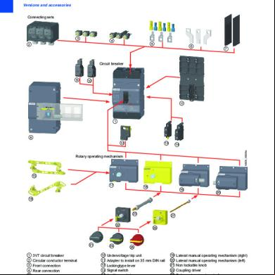
Siemens Mccb 3vt1 Up To 160 Amp 33k1o
January 2022 0
Siemens 3vt Mccb 704a47
December 2019 36
Siemens 3vt2 Mccb Accessories 4i5q5v
November 2019 29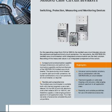
Siemens Mccb 3vl 55v59
December 2019 75
August 2021 0