Rudder Calculation 3r5234
This document was ed by and they confirmed that they have the permission to share it. If you are author or own the copyright of this book, please report to us by using this report form. Report 2z6p3t
Overview 5o1f4z
& View Rudder Calculation as PDF for free.
More details 6z3438
- Words: 970
- Pages: 8
RUDDER CALCULATION LOA (m) LBP (m) 69.63
B(m) 61
D(m) 15.4
No of Screw Step 1
1
5.07
V (Knots) 13
Type
Spade Rudder
RUDDER AREA For normal supply vessels the range of rudder area is 3-4 % of (L*T) Taking the rudder area to be 3.5 % of (L*T)
a
Ar b
T(m) 6.04
5.26 m2
Using DNV Rule A = TL/100 [1+25 (B/L) 2]
For normal seagoing ships Where
A c
8.02 m2
Average of Above two areas are taken as a Rudder Area Ar
Step 2
7 m2
RUDDER GEOMETRY Area = b * c
T = 1.4b+X
b
3.43 m
c
1.94 m
Aspect Ratio = Span / Chord Step 3
RUDDER MAXIMUM ANGLE
a
αmax = (5/7)*ԃmax
25 deg
Rudder Deflection Rate ԃmin = (24 * V)/L ԃmin
X = 0.05D-.0055D X 0.26878 b - Span C - Chord
AR
1.77
Where,
αmax b
A - Rudder area (m2) T - Ships Draught (m) LBP - Ships Length (m)
5.11 deg/sec
αmax - Angle of Attack ԃmax - Rudder deflection Angle ԃmax = 33 - 35 for sea-going with conventional rudder
Step 4
RUDDER PROFILE Taper Ratio is taken as C = (Ct + Cr)/2
0.5
Taper Ratio = Ct/Cr
Cr
2.58 m
Ct
1.29 m
Sweep back angle is taken to be
7 deg
Step 5
LOCATION OF RUDDER TURNING AXIS
a
For Tip
b
c
(Apporx)
0.122173
BC = b/2 tan 7
BC
0.2105413 m
BD = ct/4
BD
0.3226511 m
AC = EF = C/4
AC = EF
0.4839767 m
AD = AB+BD
AD
0.5960865 m
IJ = b/2 tan7
IJ
0.2105413 m
JL = Cr/4
JL
0.6453023 m
HI = EF = C/4
HI = EF
0.4839767 m
HL = HI+IJ+JL
HL
1.3398203 m
KL = HL-HK
KL
0.7437338 m
For Root
Let's take 25% of Area to be at forward part of the rudder Stock Ar/4
1.6597705 m2
Step 6
RUDDER CONSTRUCTION
a
Rudder Stock
ds = 83.3 Kr (FR(V+3)2(AR2XPF2+N2)1/2)1/3 Where,
ds
158.885 mm
Kr - Rudder coefficient FR - Rudder profile coefficient
0.248
Xpf = (0.12 * Ar)/6
0.133
1
Step 7
RUDDER BEARING
a
Depth ZB = 1.25 ds
Zb
198.61 mm
T= 0.2ds
T
31.78 mm
b
Clearance = 0.001*ds + 1 but not less than 1.5 mm Clearance
1.2 mm
Step 8
RUDDER SCANTLING
a
Plate Thickness t= K(0.001Yw+0.61)[4-Yw /Xw](1.45+0.1(ds) 1/2) Where, 1 K Yw = Vertical spacing between the horizontal web in mm. Xw = horizontal spacing of the vertical web in mm ds = the basic stock diameter, mm Yw t
600 mm 10.93 mm
Xw
900 mm
step 8
Rudder Construction 1
Rudder Stock
Basic stock diameter ds ds = 83.3 Kr (FR(V+3)2(AR2XPF2+N2)1/2)1/3 ԃs
where
Kr=Rudder coefficient = 0.248 FR= Rudder profile coefficient =1.0 V= Service speed =16 Kn AR = Rudder area =10.5 m2
XPF = 0.12 AR / YR YR =Depth of rudder at the center line of stock
step2 Rudder Bearing
Depth ZB = 1.2 ds
Zb=
mm
Minimum thickness of the wall for the lower bearing is to be taken as the lesser of 0.2ԃ or 100mm
T= 0.2ds
T=
mm
minimum7.0N/mm^2given bearing pressure on the projected area of the lowest main bearing for metal
RUDDER CALCULATION
LOA (m) LBP (m) B(m) D(m) T(m) V (Knots) 322.26 305.4 50.9 25.45 18.97 13 No of Screw Step 1
98.49 m2
Using DNV Rule A = TL/100 [1+25 (B/L) 2] Where
A
98.17 m2
For normal seagoing ships A - Rudder area (m2) T - Ships Draught (m) LBP - Ships Length (m)
Average of Above two areas are taken as a Rudder Area Ar
Step 2
Spade Rudder
For normal supply vessels the range of rudder area is 3-4 % of (L*T) Taking the rudder area to be 3.5 % of (L*T) Ar
c
Type
RUDDER AREA
a
b
2
98 m2
RUDDER GEOMETRY Area = b * c b
T = 1.4b+X
X = 0.05D-.0055D X 1.132525
12.74 m
b - Span C - Chord
c
7.72 m
Aspect Ratio = Span / Chord Step 3
RUDDER MAXIMUM ANGLE
a
αmax = (5/7)*ԃmax
AR
1.65
Where, αmax - Angle of Attack ԃmax - Rudder deflection Angle
αmax b
25 deg
Rudder Deflection Rate
ԃmax = 33 - 35 for sea-going with conventional rudder
ԃmin = (24 * V)/L ԃmin
Step 4
1.02 deg/sec
RUDDER PROFILE Taper Ratio is taken as C = (Ct + Cr)/2
0.5
Taper Ratio = Ct/Cr
Cr
10.29 m
Ct
5.14 m
Sweep back angle is taken to be
7 deg
(Apporx)
Step 5
LOCATION OF RUDDER TURNING AXIS
a
For Tip
b
c
0.122173
BC = b/2 tan 7
BC
0.7822023 m
BD = ct/4
BD
1.2862295 m
AC = EF = C/4
AC = EF
1.9293443 m
AD = AB+BD
AD
2.4333715 m
IJ = b/2 tan7
IJ
0.7822023 m
JL = Cr/4
JL
2.5724591 m
HI = EF = C/4
HI = EF
1.9293443 m
HL = HI+IJ+JL
HL
5.2840057 m
KL = HL-HK
KL
2.8506342 m
For Root
Let's take 25% of Area to be at forward part of the rudder Stock Ar/4
24.581879 m2
Step 6
RUDDER CONSTRUCTION
a
Rudder Stock
ds = 83.3 Kr (FR(V+3)2(AR2XPF2+N2)1/2)1/3 Where,
ds
1414.525 mm
Kr - Rudder coefficient FR - Rudder profile coefficient
0.248
Xpf = (0.12 * Ar)/6
0.360
Step 7
RUDDER BEARING
a
Depth ZB = 1.25 ds
Zb
1768.16 mm
T= 0.2ds
T
282.90 mm
b
Clearance = 0.001*ds + 1 but not less than 1.5 mm Clearance
2.4 mm
Step 8
RUDDER SCANTLING
a
Plate Thickness t= K(0.001Yw+0.61)[4-Yw /Xw](1.45+0.1(ds) 1/2) Where, K 1 Yw = Vertical spacing between the horizontal web in mm. Xw = horizontal spacing of the vertical web in mm ds = the basic stock diameter, mm Yw t
600 mm 21.02 mm
Xw
900 mm
1
Related Documents c2h70

Rudder Calculation 3r5234
October 2019 70
H2 Rudder 573h50
November 2019 98
Rudder Construction 2e452y
October 2019 79
Describe The Rudder Trunk 256s6e
April 2022 0
Rudder Lock 2ng31
November 2021 0
The Rudder 5g584s
January 2021 0More Documents from "Santosh Kumar" 5xg65

Question Paper 'solid Waste Management' (ce-4104)-be(civil) Viii Sem-uit-rgpv-bhopal-dec-2016 6n6j42
November 2019 39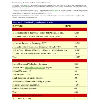
Engineering Education In India:total No. Of Seats States Wise For B.tech/b.arch s5n5o
November 2019 51
Case Study On Eyetex 1o6447
December 2019 62
English Grammar 28-01-2017 3q503w
October 2020 0
Data Sheet Of Ic Uc 3844 Part1 2r7q
December 2019 37