Pickit 3 Poster 51792a a352u
This document was ed by and they confirmed that they have the permission to share it. If you are author or own the copyright of this book, please report to us by using this report form. Report 2z6p3t
Overview 5o1f4z
& View Pickit 3 Poster 51792a as PDF for free.
More details 6z3438
- Words: 657
- Pages: 1
Using
In-Circuit DeBugger
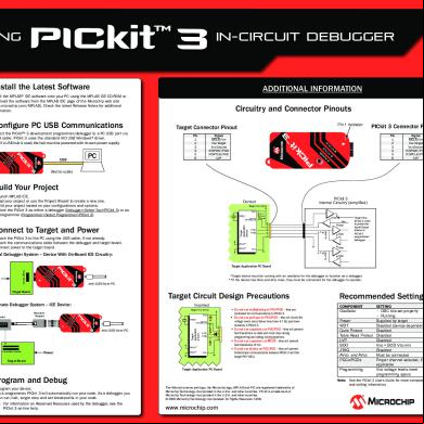
➊ Install the Latest Software
ADDITIONAL INFORMATION
Install the MPLAB® IDE software onto your PC using the MPLAB IDE CD-ROM or the software from the MPLAB IDE page of the Microchip web site (www.microchip.com/MPLAB). Check the latest Release Notes for additional information.
➋ Configure PC USB Communications
Connect the PICkit™ 3 development programmer/debugger to a PC USB port via a USB cable. PICkit 3 uses the standard HID USB Windows® driver. Note: If a USB hub is used, the hub must be powered with its own power supply.
USB
PC
Circuitry and Connector Pinouts Pin 1 Indicator
Target Connector Pinout Pin 1 2 3 4 5 6
Signal MCLR/VPP VDD Target VSS Ground ICSPDAT/PGD ICSPCLK/PGC LVP
PICkit 3 Connector Pinout Pin 1 2 3 4 5 6
Signal MCLR/VPP VDD Target VSS Ground ICSPDAT/PGD ICSPCLK/PGC LVP
(Not to scale.)
Build Your Project 1. 2. 4. 5.
Launch MPLAB IDE. Load your project or use the Project Wizard to create a new one. Build your project based on your configurations and options. Select the PICkit 3 as either a debugger (Debugger>Select Tool>PICkit 3) or as a programmer (Programmer>Select Programmer>PICkit 3).
Correct Target VDD (tVDD) VDD XTAL*
Target Application Device
VPP/MCLR
Connect to Target and Power 1. Attach the PICkit 3 to the PC using the USB cable, if not already. 2. Attach the communications cable between the debugger and target board. 3. Connect power to the target board.
PGC PGD
PICkit 3 Internal Circuitry (simplified)
4.7 10 kΩ Typical
tVDD 2 1 5 4 3
VPP tVDD 4.7 kΩ
tVDD
Target VDD (tVDD) is used to power the Input/Output drivers in PICkit 3 programmer/ debugger
AVDD** AVSS**
tVDD
VSS 4.7 kΩ
Typical Debugger System – Device With On-Board ICE Circuitry:
tVDD
Target Application PC Board Target Device
Power
*Target device must be running with an oscillator for the debugger to function as a debugger. **If the device has AVDD and AVSS lines, they must be connected for the debugger to operate.
mini-USB from PC
Target Board
Target Circuit Design Precautions
Alternate Debugger System – ICE Device:
Incorrect Target VDD (tVDD)
Standard Adapter
Header
VDD XTAL*
X
mini-USB from PC
Target Application Device
VPP/MCLR
Device-ICE
PGC PGD
X X
X
2 1 5 4 3
AVDD** Transition Socket
Power
AVSS**
VSS
• Do not use mulitplexing on PGC/PGD – they are dedicated for communications to PICkit 3. • Do not use pull-ups on PGC/PGD – they will divide the voltage levels since these lines have 4.7 kΩ pull-down resistors in PICkit 3. • Do not use capacitors on PGC/PGD – they will prevent fast transitions on data and clock lines during programming and debug communications. • Do not use capacitors on MCLR – they will prevent fast transitions of VPP. • Do not use diodes on PGC/PGD – they will prevent bidirectional communication between PICkit 3 and the target PIC® MCU.
Target Board
Target Application PC Board
➎ Program and Debug
1. Program your device. 2. As a programmer, PICkit 3 will automatically run your code. As a debugger, you can run, halt, single step and set breakpoints in your code.
The Microchip name and logo, the Microchip logo, MPLAB and PIC are ed trademarks of Microchip Technology Incorporated in the U.S.A. and other countries. PICkit is a trademark of Microchip Technology Incorporated in the U.S.A. and other countries. © 2008 Microchip Technology Incorporated. All Rights Reserved. 12/08
Note: For information on Reserved Resouces used by the debugger, see the PICkit 3 on-line help.
www.microchip.com
Recommended Settings COMPONENT Oscillator
SETTING • OSC bits set properly • Running Power Supplied by target WDT Disabled (device dependent) Code Protect Disabled Table Read Protect Disabled LVP Disabled BOD VDD > BOD VDD min JTAG Disabled AVDD and AVSS Must be connected PGCx/PGDx Proper channel selected, if applicable Programming VDD voltage levels meet programming specs Note: See the PICkit 3 ’s Guide for more component and setting information.
DS51792A
In-Circuit DeBugger
➊ Install the Latest Software
ADDITIONAL INFORMATION
Install the MPLAB® IDE software onto your PC using the MPLAB IDE CD-ROM or the software from the MPLAB IDE page of the Microchip web site (www.microchip.com/MPLAB). Check the latest Release Notes for additional information.
➋ Configure PC USB Communications
Connect the PICkit™ 3 development programmer/debugger to a PC USB port via a USB cable. PICkit 3 uses the standard HID USB Windows® driver. Note: If a USB hub is used, the hub must be powered with its own power supply.
USB
PC
Circuitry and Connector Pinouts Pin 1 Indicator
Target Connector Pinout Pin 1 2 3 4 5 6
Signal MCLR/VPP VDD Target VSS Ground ICSPDAT/PGD ICSPCLK/PGC LVP
PICkit 3 Connector Pinout Pin 1 2 3 4 5 6
Signal MCLR/VPP VDD Target VSS Ground ICSPDAT/PGD ICSPCLK/PGC LVP
(Not to scale.)
Build Your Project 1. 2. 4. 5.
Launch MPLAB IDE. Load your project or use the Project Wizard to create a new one. Build your project based on your configurations and options. Select the PICkit 3 as either a debugger (Debugger>Select Tool>PICkit 3) or as a programmer (Programmer>Select Programmer>PICkit 3).
Correct Target VDD (tVDD) VDD XTAL*
Target Application Device
VPP/MCLR
Connect to Target and Power 1. Attach the PICkit 3 to the PC using the USB cable, if not already. 2. Attach the communications cable between the debugger and target board. 3. Connect power to the target board.
PGC PGD
PICkit 3 Internal Circuitry (simplified)
4.7 10 kΩ Typical
tVDD 2 1 5 4 3
VPP tVDD 4.7 kΩ
tVDD
Target VDD (tVDD) is used to power the Input/Output drivers in PICkit 3 programmer/ debugger
AVDD** AVSS**
tVDD
VSS 4.7 kΩ
Typical Debugger System – Device With On-Board ICE Circuitry:
tVDD
Target Application PC Board Target Device
Power
*Target device must be running with an oscillator for the debugger to function as a debugger. **If the device has AVDD and AVSS lines, they must be connected for the debugger to operate.
mini-USB from PC
Target Board
Target Circuit Design Precautions
Alternate Debugger System – ICE Device:
Incorrect Target VDD (tVDD)
Standard Adapter
Header
VDD XTAL*
X
mini-USB from PC
Target Application Device
VPP/MCLR
Device-ICE
PGC PGD
X X
X
2 1 5 4 3
AVDD** Transition Socket
Power
AVSS**
VSS
• Do not use mulitplexing on PGC/PGD – they are dedicated for communications to PICkit 3. • Do not use pull-ups on PGC/PGD – they will divide the voltage levels since these lines have 4.7 kΩ pull-down resistors in PICkit 3. • Do not use capacitors on PGC/PGD – they will prevent fast transitions on data and clock lines during programming and debug communications. • Do not use capacitors on MCLR – they will prevent fast transitions of VPP. • Do not use diodes on PGC/PGD – they will prevent bidirectional communication between PICkit 3 and the target PIC® MCU.
Target Board
Target Application PC Board
➎ Program and Debug
1. Program your device. 2. As a programmer, PICkit 3 will automatically run your code. As a debugger, you can run, halt, single step and set breakpoints in your code.
The Microchip name and logo, the Microchip logo, MPLAB and PIC are ed trademarks of Microchip Technology Incorporated in the U.S.A. and other countries. PICkit is a trademark of Microchip Technology Incorporated in the U.S.A. and other countries. © 2008 Microchip Technology Incorporated. All Rights Reserved. 12/08
Note: For information on Reserved Resouces used by the debugger, see the PICkit 3 on-line help.
www.microchip.com
Recommended Settings COMPONENT Oscillator
SETTING • OSC bits set properly • Running Power Supplied by target WDT Disabled (device dependent) Code Protect Disabled Table Read Protect Disabled LVP Disabled BOD VDD > BOD VDD min JTAG Disabled AVDD and AVSS Must be connected PGCx/PGDx Proper channel selected, if applicable Programming VDD voltage levels meet programming specs Note: See the PICkit 3 ’s Guide for more component and setting information.
DS51792A
Related Documents c2h70
Pickit 3 Poster 51792a a352u
July 2021 0
Pickit 3 225c2u
November 2019 46
Pickit 3 Programmer 1 0 Ree 521f16
December 2019 19
Pickit 3 Programmer Application 's Guide 50002158a 6l1r5l
November 2019 43
Gsm Modernization Poster 3 65p3w
May 2020 5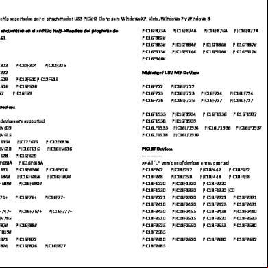
Pickit 2 Dispositivos Soportados 1ce5r
February 2023 0More Documents from "Sixto Aguero" 1z4v4o

6g3p1u
February 2023 0
Pickit 3 Poster 51792a a352u
July 2021 0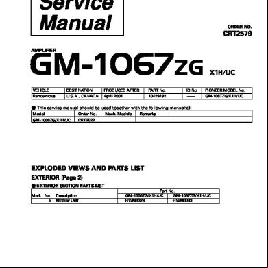
Gm 1067 Amplifier 263456
June 2022 0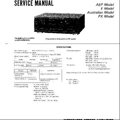
Sony Ta-a590, Lbt-a595.pdf 36641v
March 2021 0
Servidorweb 373v1h
November 2020 0