Pcs-9705 6sj3p
This document was ed by and they confirmed that they have the permission to share it. If you are author or own the copyright of this book, please report to us by using this report form. Report 2z6p3t
Overview 5o1f4z
& View Pcs-9705 as PDF for free.
More details 6z3438
- Words: 1,178
- Pages: 3
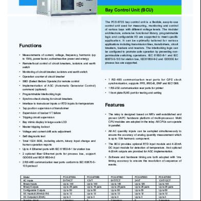
PCS-9705 Bay Control Unit (BCU)
Functions • Measurements of current, voltage, frequency, harmonic (up to 15th), power factor, active/reactive power and energy • Remote/local control of circuit breakers, isolators and earth switch
The PCS-9705 bay control unit is a flexible, easy-to-use control unit used for measuring, monitoring and control of various bays with different voltage levels. The modular architecture, extensive functional library, programmable logic and configurable I/O are ed to meet specific application. It can be optimally tailored for various applications including transmission lines, transformers, circuit breakers, busbars and reactors. The interlocking logic can be configured to promote safe operation by preventing nonpermissible switching operations. IEC 61850-8-1 and IEC 60870-5-103 for station bus, IEC61850-9-2 and GOOSE for process bus are ed.
• Monitoring of circuit breaker, isolators and earth switch • Operation counter of circuit breaker • SBO (Select Before Operate) for remote control • Implementation of AGC (Automatic Generator Control) command (optional) • Programmable Interlocking logic
• 1 RS-485 communication rear ports for GPS clock synchronization, s PPS, IRIG-B, SNP and IEC1588. • 1 RS-232 communication rear ports for printer • 1 front plate RJ45 port for testing and setting
• Synchro-check closing for circuit breakers • Interface to transducer inputs or RTD inputs for temperature • Tap position supervision of transformer • Supervision of busbar VT failure
• The relay is designed based on NR’s well established and proven UAPC hardware platform of multi-processor. Multi U modules are adopted in the relay. All Us can operate in parallel.
• Tripping circuit supervision • Bay mimic display in large scale LCD • Master tripping lockout • Voltage and current drift auto adjustment • Self diagnostic test • Total 1024 SOE, including alarm, binary input change and human operation reports • Up to 4 Ethernet ports with IEC 61850-8-1 for station bus • 2 optional fiber Ethernet ports for process bus, GOOSE and IEC61850-9-2 • 2 RS-485 communication rear ports conform to IEC 60870-5103 protocol
Model AC inputs Binary Inputs Binary Outputs Configurable Outputs DC Inputs(4-20mA,0-5V) DC Outputs(4-20mA) Synchro-check Interlocking Logic to ECVT(optional) IEC61850 Process Bus(optional)
296
read more on www.nrelect.com
PCS-9705A 5VT/4CT Up to 140 Up to 25 pairs Up to 50 Up to 12 Up to 4 1 breaker Yes Yes Yes
Features
• All AC quantity inputs can be sampled simultaneously to ensure the accuracy of analog quantity measurement which is up to 15th harmonic component. • The BCU provides optional RTD input module and 4-20mA DC input module for detection of temperature. And optional 4-20mA outputs are provided for AGC implementation. • Software and hardware timing are both adopted with 1ms timing accuracy to ensure the resolution of sequence of events.
PCS-9705B 13VT Up to 140 Up to 15 pairs Up to 50 Up to 12 Up to 4 0 Yes Yes Yes
Read more on the web
www.nrelect.com
PCS-9705C 8VT/7CT Up to 140 Up to 25 pairs Up to 50 Up to 12 Up to 4 2 breakers Yes Yes Yes
PCS-9705D 24VT Up to 120 Up to 25 pairs Up to 50 Up to 12 Up to 4 0 Yes Yes Yes
PCS-9705E 13VT/12CT Up to 140 Up to 25 pairs Up to 50 Up to 12 Up to 4 3 breakers Yes Yes Yes
• The control circuits adopt many block, permit and facilities, including bay level transverse interlock function based on network communication so that the security of local and remote control can be ensured.
• The network of equipments adopts 100M optic fiber or twisted wire Ethernet. • It adopts integral front plate and plug-in module structure. High and low voltage circuits are separated strictly which enhances EMC immunity performance.
• Large scale LCD provides graph and text man-machineinterface which makes operation and inter-rogation convenient.
• Low power consumption and wide ambient temperature range.
Technical data Power Supply Standard
IEC 60255-11:2008
Voltage Range
88 to 300 Vdc or 88 to 264 Vac
Permissible AC ripple voltage
≤15% of the nominal auxiliary voltage <20W (for conventional substation application) <25W (for smart substation application) <25W (for conventional substation application) <30W (for smart substation application)
Burden
Quiescent condition Operating condition
Analog Current Standard Phase rotation Nominal frequency (fn) Nominal range Accuracy Rated current (In) Linear to continuously for 10s for 1s for half a cycle
Thermal withstand capability Burden
IEC 60255-27:2005 ABC 50Hz, 60Hz 90% ~ 110% fn 0.2 class 1A 0.05In~2In 2In 12In 30In 75In < 0.2VA/phase @In
5A
< 0.4VA/phase @In
Analog voltage Standard Phase rotation Nominal frequency (fn) Nominal range Rated phase-to-phase voltage (Un) linear to Accuracy
IEC 60255-6, IEC60288 ABC 50Hz, 60Hz 90% ~ 110% fn 100~130V 1~130V 0.2 class 130V 200V 250V < 0.10VA/phase @Un
continuously 10s 1s
Thermal withstand capability Burden
Transducer Inputs Standard Input range Input resistance Accuracy
IEC 60255-1:2009 0-20mA 235Ω 0.5 class
0~5V 4.4 kΩ 0.5 class
0~48V 54.2 kΩ 0.5 class
0~250V 248 kΩ 0.5 class
Binary Inputs Standard Rated voltage Rated current Pickup voltage Maximum permissive voltage Withstand
IEC 60255-1:2009 24V 48V 1.2mA 2.4mA 55%~70% of rated voltage 120% rated voltage 2000Vac, 2800Vdc
110V 1.1mA
Read more on the web
www.nrelect.com
125V 1.25mA
220V 2.2mA
250V 2.5mA
read more on www.nrelect.com
297
Resolving time for logic input
<1ms
Binary Outputs Item Output mode Max system voltage
Tripping Potential free 380Vac, 250Vdc
Signal
Voltage across open
1000V RMS for 1 minute 5.0A @ 380Vac 5.0A @ 250Vdc <8ms <5ms 6A@3s [email protected] 0.6A @ 48Vdc, L/R=40ms 0.1A @ 110Vdc, L/R=40ms 0.05A @ 220Vdc, L/R=40ms 380V AC 250V DC 1000V RMS for 1minute
1200V RMS for 1 minute 8.0A @ 380Vac 8.0A @ 250Vdc <10ms <8ms 10A@3s [email protected] 0.6A @ 48Vdc, L/R=40ms 0.3A @ 110Vdc, L/R=40ms 0.2A @ 220Vdc, L/R=40ms 380V AC 250V DC 1200V RMS for 1 minute
Continuous carry Pickup time Drop-off time Short duration current Breaking capacity (L/R=40ms) Maximal working voltage Test voltage across open
380Vac, 250Vdc
Mechanical Specifications Enclosure dimensions (W×H×D) Trepanning dimensions (W×H) Mounting Protection class Standard Front side Other sides Rear side, connection terminals Pollution degree
482.6× 177.0 ×230.2 (unit: mm) 450.0×179.0, M6 screw (unit: mm) Flush mounted IEC 60255-1:2009 IP40, up to IP51 (Flush mounted) IP30 IP20 2
Ambient Temperature and Humidity Range Standard Operating temperature Transport and storage temperature range Permissible humidity Altitude
IEC 60255-1:2009 -40°C to +70°C Note: The operating temperature of LCD is -20°C ~ +70°C -40°C ~ +70°C 5% ~ 95%, condensation not permissible <3000m
Communication Port - Ethernet Port for RTU/SCADA Connector type Transmission rate Transmission standard Transmission distance Protocol Safety level
RJ-45 100Mbits/s 10Base-T/100Base-TX <100m IEC 60870-5-103:1997, DNP 3.0 or IEC 61850 Isolation to ELV level
- Station Level Interface Characteristic Optical fiber type Connector type Wave length Transmission distance Minimum transmission power Reception sensitivity Margin
Glass optical fiber Multi-mode ST, SC 1310nm <2000m -20dBm -30dBm Min. +3.0dB
- Process Level Interface Characteristic Optical fiber type Connector type Wave length Transmission distance Minimum transmission power Reception sensitivity Margin
Glass optical fiber Multi-mode LC 1310nm <2000m -20dBm -30dBm Min. +3.0dB
- Print Port 298
read more on www.nrelect.com
Read more on the web
www.nrelect.com
More Documents from "elkhalfi" 1n5o6p

Vlf Tangente Delta 01 93y1y
August 2021 0
Formation Commutation j5u1k
July 2021 0