Manual Tecnico De Abilix 3j5b56
This document was ed by and they confirmed that they have the permission to share it. If you are author or own the copyright of this book, please report to us by using this report form. Report 2z6p3t
Overview 5o1f4z
& View Manual Tecnico De Abilix as PDF for free.
More details 6z3438
- Words: 3,518
- Pages: 16
Ccon102
sensor blocks, control blocks and program blocks. Besides, several block libraries that are not used frequently can also be called from the menu bar.
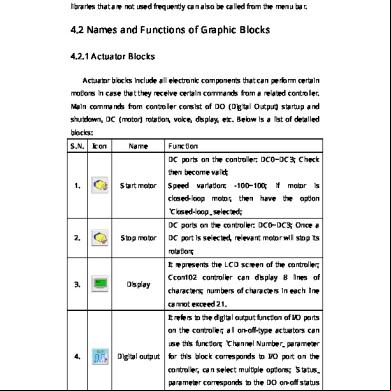
4.2 Names and Functions of Graphic Blocks 4.2.1 Actuator Blocks Actuator blocks include all electronic components that can perform certain motions in case that they receive certain commands from a related controller. Main commands from controller consist of DO (Digital Output) startup and shutdown, DC (motor) rotation, voice, display, etc. Below is a list of detailed blocks: S.N.
Icon
Name
Function DC ports on the controller: DC0~DC3; Check then become valid;
1.
Start motor
Speed
variation:
-100~100;
if
motor
is
closed-loop motor, then have the option “Closed-loop” selected; DC ports on the controller: DC0~DC3; Once a 2.
Stop motor
DC port is selected, relevant motor will stop its rotation; It represents the LCD screen of the controller;
3.
Display
Ccon102 controller can display 8 lines of characters; numbers of characters in each line cannot exceed 21. It refers to the digital output function of I/O ports on the controller; all on-off-type actuators can use this function; “Channel Number” parameter
4.
Digital output
for this block corresponds to I/O port on the controller, can select multiple options; “Status” parameter corresponds to the DO on-off status of the I/O port; Page 24
Ccon102
It corresponds to the digital output function of 5.
LED
relative I/O port on the controller; generally used for colored LED in the robotics kit; refer to “digital output” instruction to find more details; It corresponds to the digital output function of
6.
Electromagnet
I/O ports on the controller; generally used for the electromagnet in the robotics kit; refer to “digital output” instruction to find more details; It refers to the buzzer inside the controller; with
7.
Tone
this function, a song can be made; 2 IMP parameters available for this block: Time and Frequency;
8.
Calculate
Define integer variable or do mathematical calculation; Wait for a certain period of time; within the
9.
Wait
pre-set time, controller doesn’t make any motion; unit of time is second; Initialize the servo motor before using it; actual function is to switch on the RS485 power;
10.
Initialize servo Note: The program will pause for a second when executes the block, so we suggest the to put it at the top of a program. It corresponds to RS485 function of I/O ports; used for controlling digital servo by RS485 function (different from DO and DC control mode); each servo has a ID; selecting all
11.
Digital servo
servos will control all servos linked to the controller; speed refers to the rotary speed; speed varies from 0 to 1023; position refers to destination position angle; position angle varies from -150° to 150°; 0° refers to the position
Page 25
Ccon102
where the notch on the driving plate and notch on the servo case can align each other; Note: DC motor related blocks used in flow chart equal to “motors” provided in robotics kits.
4.2.2 Sensor Blocks Sensor blocks include all collection modules that can gather environment data for the controller. Controller collects environment data via functions such as AI, DO, counter, etc. Below is a detailed list of sensor blocks: S.N.
Icon
Name
Function Read anaput value from relative I/O port on the controller; AI “Channel Number” corresponds to I/O port number on the controller; Clicking “AI
1.
Analog
Var1” can help you rename the variable; Clicking
input
“Convert it to be a ‘Compare block’ after detection” can switch the block to be a judgment block; “Condition loop” block will be referred in control blocks in detail; Read anaput value from relative I/O port on
2.
Light
the controller; generally used by light sensor for
detection
data collection; refer to “Anaput” instruction to find more details of its usage; Read anaput value from relative I/O port on
3.
Temp
the controller; generally used by temp sensor for
detection
data collection; refer to “Anaput” instruction to find more details of its usage; Read anaput value from relative I/O port on
4.
Greyscale
the controller; generally used by greyscale sensor
detection
for data collection; refer to “Anaput” instruction to find more details of its usage;
Page 26
Ccon102
Read anaput value from relative I/O port on 5.
Flame
the controller; generally used by flame sensor for
detection
data collection; refer to “Anaput” instruction to find more details of its usage; Read anaput value from relative I/O port on
6.
Voice
the controller; generally used by voice sensor for
detection
data collection; refer to “Anaput” instruction to find more details of its usage; Read digital input value from relative I/O port on the controller; DI “Channel Number” corresponds to I/O port number on the controller; Clicking “DI
7.
Digital input
Var1” can help you rename the variable; Clicking “Convert it to be a ‘Compare block’ after detection” can switch the block to be a judgment block; “Condition loop” block will be referred in control blocks in detail; Read digital input value from relative I/O port on
8.
Switch
the controller; generally used by switch sensor for
detection
data collection; refer to “Digital input” instruction to find more details of its usage; Read digital input value from relative I/O port on
9.
Magnetism
the controller; generally used by electromagnet
detection
for data collection; refer to “Digital input” instruction to find more details of its usage; Read button status info of the controller; “Start”
10.
Button status
key on Ccon102 can be read; “Enter” key, “Left” key and “Right” key of the controller can be read; With this block, keys on the controller can be used as a button in the software;
11.
System time
Read current time of the system timer inserted in the controller; unit of return value is second;
Page 27
Ccon102
12.
Reset time
Clear system time, and start timing again; Start the counting function of related I/O port on the controller; “Counter channel” of this block corresponds to relative I/O port number on the
13.
Start counter
controller; Before counting , make sure the right port has been started; After rotating counter starts counting, the controller will record pulse signal of the port and store in “System variable” (the system variable should be assigned for the relative port);
14.
15.
Clear counter
Get counter
Clear the recorded value of the port that is linked to the rotating counter; (empty value in “system variable”) Get the accumulated value from the port; (Assign the value in the system value to a -defined variable, such as “Counter Var1”) End the counting function of relative I/O port on the controller; “Counter channel” of this block
16.
Stop
corresponds to the relative I/O port on the
counter
controller; After closing this port, the “System variable” area assigned for the rotating counter will be drawn back;
4.2.3 Control Blocks In program, return value from each port generally has either of the below two functions: data storage or judgment making. And judgment making is used more frequently. As to VJC software, three judgment modes are available, they are: while sentence, if…else… sentence, for sentence. If a program needs to make a judgment, there should be an object and reference value. The object for comparison is often the return value of a certain
Page 28
Ccon102
sensor or updated variable value. So each block that is capable of “reading” function in sensor blocks can be converted to a “Condition judgment” block. Below is a detailed list of control blocks: S.N.
Icon
Name
Function The block works as “for” sentence in C language.
1.
Multiple loop
“Loop number” parameter in this block means how many times the block will loop. Exact loop number is specified by s The block works as “while (1)” sentence in C
2.
Infinite loop
language. It repeats the body inside the sentence infinitely. The block works as “while” sentence in C language. Parameters are the conditions that can
3.
Condition loop
be set by s. As long as the loop condition is met, the loop will continue, or the loop will be terminated and the program will run below sentences. The block works as “if…else…” sentence in C language. Parameters can be set by s. If the
4.
Compare
condition is met, the program will implement the “Y” branch, or the program will implement the “N” branch. The block works as “Break” sentence in C
5.
Break
language. It is used inside a certain loop. When the program implements to this block, the quit the current loop.
Condition expression “Condition” mentioned above is an expression including three parts: left part, middle part and right part. Left and right part can be formulas, variables or numerical values, while the middle part can be ==, !, =, >, <, >=, etc. Return
Page 29
Ccon102
value of such condition sentence only has two possibilities, they are 0 and 1. If return value is 0, the condition is not met. If return value is 1, then the condition is met. When setting condition loop and condition judgment, you can find “Condition 1” and “Condition 2”. Usually we only use “Condition 1”. “Condition 2” will become valid if “Valid” option on tab “Condition 2” is selected. After “valid” on tab “Condition 2” is selected, other parameters for “Condition 2” will be activated (refer to below picture). Detailed description: Only when “Valid” selected will parameters for “Condition 2” become activated; Logic relation means the relation between “Condition 1” and “Condition 2”. Three logic relations are available, they are “AND”, “OR” and “NOT” (for C language, “&&”, “||” and “&&!” instead). Parameters for “AND”, “OR” and “NOT” can be formulas or values. Three results are available for the calculation: “Condition 1 AND Condition 2”: when both conditions are met, result is 1, or result is 0; “Condition 1” OR Condition 2”: result will be 1 if one condition is met at least, or result is 0; “Condition 1 NOT Condition 2”: If return values for both conditions are different, result is 1, otherwise result is 0;
Page 30
Ccon102
4.2.4 Program Blocks S.N.
Icon
Name
Function This block can be used to build a new subprogram. s can also reference a
1.
New subprogram
subprogram of another program. Subprogram can be taken as a package of many blocks for realizing a certain function. Subprogram can be used easily in later operations and can keep the main program relatively brief. This block is used to end a certain
2.
Subprogram
subprogram and keep the flow chart of the
return
subprogram complete. There is no practical function for the block. This block is used to end the main program
3.
End block
and keep the flow chart of the main program brief. There is practical function for this block.
Page 31
Ccon102
With this block used, s can write C code to make a program by themselves. Be sure 4.
Customize
grammars used are right, or errors will appear when compiling the program. s without a C language background are not suggested to use this block.
4.3 Variables Box For graphic blocks, you may find “Variable” option or sensor variable option. After clicking that option, you will find a pop-up dialogue box as shown below. The dialogue box is the variables box.
Variables box integrates all variables used in flow charts. s can switch types of variables by clicking icons of different sensors or others in the picture as shown above. Then s can choose a serial number from 10 options above icons on the picture as shown above. Highlighted option (yellow Page 32
Ccon102
background) means the option is selected. There is also a key icon after the selected option. In the area of icons, gray box means the variable type is unavailable.
4.4 Other Block Libraries for Flow Chart Programming For advanced s, we have developed several special blocks. To use these blocks, you should list them on the left of the flow chart programming area. You can find these special blocks in “Tools” of the main menu. After clicking the specific blocks, they will be listed on the left to the flow chart programming area.
4.4.1 Line Tracing Blocks “Line Tracing Blocks” are the blocks library specially added for line tracers with grayscale sensors. It is required that the grayscale sensors should be lined in a row in the front of the line tracer. The number of grayscale sensors can be 5 or 7. We suggest new s to learn “6.4 Line Tracing Principle of Grayscale Sensors” as the first step. *Initialize*
This block is for setting the properties of line tracer. It determines which port the motor or the grayscale sensor will be connected, output power of the motor etc.
Page 33
Ccon102
Closed-loop Motor: If the motor that you use is a closed-loop motor, you need to check this item. However, if your motor isn’t, do not check this item; otherwise, your motor will rotate at the max speed. (Motor) Port: Two motors on the line tracer. One for the left wheel, one for the right wheel. The can decide which port the motor will be connected to. Power: The actual speed the motor generates is the speed value that the programs multiplies by the power value. If the power values are positive but the robot moves backwards, the can set the power values negative. In this case, the won’t consider about turning while setting the motor speed. Number of Grayscale Sensors: If your robot is a line tracer with 7 grayscale sensors, please select “7 Grayscale Sensor”; If yours is one with 5 greyscale sensors, please select “5 grayscale sensors”. If yours is the one with neither 7 nor 5 grayscale sensors, then the “Line Tracing Blocks” are not applicable, the needs to customize by him/herself. (Grayscale) Port: It determines which I/O port should one grayscale sensor connects to. Page 34
Ccon102
Types of Lines If the line is black (white ground), choose “Black Line”. If the line is white (black ground), choose “White Line”. The needs to note that the “white” and “black” are concepts to grayscale sensors, for example, glass is colorless, but the grayscale sensor will identify it as black. Turn on DO?: This item determines whether to turn on the Digital Output. Select “Yes” to switch on all the grayscale sensors. Deviation of Threshold Value: The threshold value (i.e. critical value) usually refers to “(Minimum value + Maximum value)×0.5”. However, under some particular circumstances, you may need the threshold value to deviate toward the minimum value by decreasing the “0.5”. The needs to note that the threshold value shouldn’t be too small, like “(2+8)×0.5”equals “5”, if the changes “0.5” into “0.1”, the threshold value will be invalid, because it’s even smaller than the minimum value. Notices: The block of “Initialize” is for setting properties of the robot. No matter the line tracing programs or threshold value of the grayscale sensor, the needs to use this block to start with. Usually, the block is at the beginning of a program. However, if types of the lines change while the line tracer is moving, for example, black line on white ground changes into white line on black ground, then the needs to add another “Initialize” block. “Initialize” block can be seen as a block that stores information of the necessary robot properties. *Environment Gathering*
This block is used to gather the value of the ground grayscale. If the robot only moves on one type of the ground, you only need to select one type accordingly. If the robot moves on both types, you need to check them both. In the flow chart program, an “Initialize” block must be put before the “Environment Gathering” block. After being operated on the controller, the can operate by
Page 35
Ccon102
instructions displayed on the controller. Take selecting both types as an example, the will go through some steps as following. A. Move the arrow to select “Yes” by pressing “Left” or “Right” button, then press “ENTER” to enter the interface of environment gathering. An instruction on the screen tells you to put the grayscale sensors on the BLACK LINE. B. Put the grayscale sensors on the BLACK LINE (refers to the “black line” on the white ground that deviates to white the most), then press “ENTER” and wait until an instruction appears on the screen telling you to put the grayscale sensors on the WHITEGROUND. C. Put the greyscale sensors on the WHITE GROUND (the “blackest” white ground with black line on it), then press “ENTER” and wait until an instruction appears on the screen telling you to put the grayscale sensors on the WHITE LINE. D.Put the grayscale sensors on the WHITE LINE (the “blackest” white line on the black ground), then press “ENTER” and wait until an instruction appears on the screen telling you to put the grayscale sensors on the BLACK GROUND. E. Put the grayscale sensors on the BLACK GROUND (the “whitest” black ground with white line on it), then press “ENTER” and wait until an instruction appears on the screen telling you that the environment gathering is OK (done). F.If the block is followed by other program blocks, the program will go on after Step E is complete. Notices: There should be an “Initialize” block before the “Environment Gathering” block, otherwise, the correct threshold value will not be gathered. The values will be stored in EEPROM10-23 in turn, in which the values gathered from “white ground with black line” will be stored in EEPROM10-16, and the values gathered from “black ground with white line” will be stored in EEPROM17-23. If EEPROM is occupied in the program, do not use EEPROM10-23; the can change the threshold value directly in EEPROM10-23 instead of using “Environment Gathering” block. *Intersection*
Page 36
Ccon102
Type of Intersection: The offset orientation of the intersections in one block. Two tips for s to select the type of intersections. . The same direction where the robot needs to turn to. If the robot needn’t to turn, choose one direction that has the less offsets. Speed of Line Tracing: When the grayscale sensor in the middle is over the line, this speed value is the speed of the motor that rotates faster. Left Turn Speed Difference: When the grayscale sensor in the middle is over the line, this difference value equals to “Speed of Line Tracing” minus speed of the left wheel(the slower wheel). Right Turn Speed Difference: When the grayscale sensor in the middle is over the line, this difference value equals to “Speed of Line Tracing” minus speed of the right wheel (the slower wheel). Times of loops: This refers to how many intersections the line tracer will . A loop will be complete when the line tracer es one intersection. The “Times of Loops” is the same as how many intersections needed to . Time after ing Intersection: How long the line tracer will move after ing the intersection. Car Stops after Completed: Whether the line tracer stops after the block is complete. *Time*
Page 37
Ccon102
When there’s no intersection or referential point on the way to destination, the line tracer can be controlled by time. However, the distance the robot moves is determined by its speed and time. The can set time, not the speed which is affected by voltage, frictional resistance etc. These factors cannot be controlled, so the distance/destination the line tracer will move to cannot be precisely controlled. *Advanced*
Page 38
Ccon102
This block will end with the return value of one sensor meeting the preset value, for example, if an IR sensor is plugged into the NO.7 I/O port, the returning value when no object is detected is 3000; when an object is detected, the returning value will be less than 500. The can therefore set the line tracer to stop by “AI(7)<500”. Sensor Port: The sensor’s I/O port number that responds to the termination of this block. Symbol: Mathematical notation that determines the relation of the return value and the preset value. Reference Value: The threshold value of the sensor that responds to the termination of this block. *Turn*
The robot motion is controlled by two motors, and turns are made by speed difference of the two motors. If we think speed as pure numerical value (speed on the counter direction will be represented as negative values), then the robot will turn to the side with smaller speed value. This block will be complete for one time after the greyscale sensor crosses a line. Crossed Lines: Refers to the lines that it’d crossed, for example, the line tracer needs to turn 180 degrees by crossing 2 lines at a crossroad. Stopped Position: It determines where the line tracer would stop over the line—“Middle”, “Deviate to left” or “Deviate to right”. The line tracer usually turns a little too much because of inertia, so when the line tracer turns left at a relatively high speed, the Page 39
sensor blocks, control blocks and program blocks. Besides, several block libraries that are not used frequently can also be called from the menu bar.
4.2 Names and Functions of Graphic Blocks 4.2.1 Actuator Blocks Actuator blocks include all electronic components that can perform certain motions in case that they receive certain commands from a related controller. Main commands from controller consist of DO (Digital Output) startup and shutdown, DC (motor) rotation, voice, display, etc. Below is a list of detailed blocks: S.N.
Icon
Name
Function DC ports on the controller: DC0~DC3; Check then become valid;
1.
Start motor
Speed
variation:
-100~100;
if
motor
is
closed-loop motor, then have the option “Closed-loop” selected; DC ports on the controller: DC0~DC3; Once a 2.
Stop motor
DC port is selected, relevant motor will stop its rotation; It represents the LCD screen of the controller;
3.
Display
Ccon102 controller can display 8 lines of characters; numbers of characters in each line cannot exceed 21. It refers to the digital output function of I/O ports on the controller; all on-off-type actuators can use this function; “Channel Number” parameter
4.
Digital output
for this block corresponds to I/O port on the controller, can select multiple options; “Status” parameter corresponds to the DO on-off status of the I/O port; Page 24
Ccon102
It corresponds to the digital output function of 5.
LED
relative I/O port on the controller; generally used for colored LED in the robotics kit; refer to “digital output” instruction to find more details; It corresponds to the digital output function of
6.
Electromagnet
I/O ports on the controller; generally used for the electromagnet in the robotics kit; refer to “digital output” instruction to find more details; It refers to the buzzer inside the controller; with
7.
Tone
this function, a song can be made; 2 IMP parameters available for this block: Time and Frequency;
8.
Calculate
Define integer variable or do mathematical calculation; Wait for a certain period of time; within the
9.
Wait
pre-set time, controller doesn’t make any motion; unit of time is second; Initialize the servo motor before using it; actual function is to switch on the RS485 power;
10.
Initialize servo Note: The program will pause for a second when executes the block, so we suggest the to put it at the top of a program. It corresponds to RS485 function of I/O ports; used for controlling digital servo by RS485 function (different from DO and DC control mode); each servo has a ID; selecting all
11.
Digital servo
servos will control all servos linked to the controller; speed refers to the rotary speed; speed varies from 0 to 1023; position refers to destination position angle; position angle varies from -150° to 150°; 0° refers to the position
Page 25
Ccon102
where the notch on the driving plate and notch on the servo case can align each other; Note: DC motor related blocks used in flow chart equal to “motors” provided in robotics kits.
4.2.2 Sensor Blocks Sensor blocks include all collection modules that can gather environment data for the controller. Controller collects environment data via functions such as AI, DO, counter, etc. Below is a detailed list of sensor blocks: S.N.
Icon
Name
Function Read anaput value from relative I/O port on the controller; AI “Channel Number” corresponds to I/O port number on the controller; Clicking “AI
1.
Analog
Var1” can help you rename the variable; Clicking
input
“Convert it to be a ‘Compare block’ after detection” can switch the block to be a judgment block; “Condition loop” block will be referred in control blocks in detail; Read anaput value from relative I/O port on
2.
Light
the controller; generally used by light sensor for
detection
data collection; refer to “Anaput” instruction to find more details of its usage; Read anaput value from relative I/O port on
3.
Temp
the controller; generally used by temp sensor for
detection
data collection; refer to “Anaput” instruction to find more details of its usage; Read anaput value from relative I/O port on
4.
Greyscale
the controller; generally used by greyscale sensor
detection
for data collection; refer to “Anaput” instruction to find more details of its usage;
Page 26
Ccon102
Read anaput value from relative I/O port on 5.
Flame
the controller; generally used by flame sensor for
detection
data collection; refer to “Anaput” instruction to find more details of its usage; Read anaput value from relative I/O port on
6.
Voice
the controller; generally used by voice sensor for
detection
data collection; refer to “Anaput” instruction to find more details of its usage; Read digital input value from relative I/O port on the controller; DI “Channel Number” corresponds to I/O port number on the controller; Clicking “DI
7.
Digital input
Var1” can help you rename the variable; Clicking “Convert it to be a ‘Compare block’ after detection” can switch the block to be a judgment block; “Condition loop” block will be referred in control blocks in detail; Read digital input value from relative I/O port on
8.
Switch
the controller; generally used by switch sensor for
detection
data collection; refer to “Digital input” instruction to find more details of its usage; Read digital input value from relative I/O port on
9.
Magnetism
the controller; generally used by electromagnet
detection
for data collection; refer to “Digital input” instruction to find more details of its usage; Read button status info of the controller; “Start”
10.
Button status
key on Ccon102 can be read; “Enter” key, “Left” key and “Right” key of the controller can be read; With this block, keys on the controller can be used as a button in the software;
11.
System time
Read current time of the system timer inserted in the controller; unit of return value is second;
Page 27
Ccon102
12.
Reset time
Clear system time, and start timing again; Start the counting function of related I/O port on the controller; “Counter channel” of this block corresponds to relative I/O port number on the
13.
Start counter
controller; Before counting , make sure the right port has been started; After rotating counter starts counting, the controller will record pulse signal of the port and store in “System variable” (the system variable should be assigned for the relative port);
14.
15.
Clear counter
Get counter
Clear the recorded value of the port that is linked to the rotating counter; (empty value in “system variable”) Get the accumulated value from the port; (Assign the value in the system value to a -defined variable, such as “Counter Var1”) End the counting function of relative I/O port on the controller; “Counter channel” of this block
16.
Stop
corresponds to the relative I/O port on the
counter
controller; After closing this port, the “System variable” area assigned for the rotating counter will be drawn back;
4.2.3 Control Blocks In program, return value from each port generally has either of the below two functions: data storage or judgment making. And judgment making is used more frequently. As to VJC software, three judgment modes are available, they are: while sentence, if…else… sentence, for sentence. If a program needs to make a judgment, there should be an object and reference value. The object for comparison is often the return value of a certain
Page 28
Ccon102
sensor or updated variable value. So each block that is capable of “reading” function in sensor blocks can be converted to a “Condition judgment” block. Below is a detailed list of control blocks: S.N.
Icon
Name
Function The block works as “for” sentence in C language.
1.
Multiple loop
“Loop number” parameter in this block means how many times the block will loop. Exact loop number is specified by s The block works as “while (1)” sentence in C
2.
Infinite loop
language. It repeats the body inside the sentence infinitely. The block works as “while” sentence in C language. Parameters are the conditions that can
3.
Condition loop
be set by s. As long as the loop condition is met, the loop will continue, or the loop will be terminated and the program will run below sentences. The block works as “if…else…” sentence in C language. Parameters can be set by s. If the
4.
Compare
condition is met, the program will implement the “Y” branch, or the program will implement the “N” branch. The block works as “Break” sentence in C
5.
Break
language. It is used inside a certain loop. When the program implements to this block, the quit the current loop.
Condition expression “Condition” mentioned above is an expression including three parts: left part, middle part and right part. Left and right part can be formulas, variables or numerical values, while the middle part can be ==, !, =, >, <, >=, etc. Return
Page 29
Ccon102
value of such condition sentence only has two possibilities, they are 0 and 1. If return value is 0, the condition is not met. If return value is 1, then the condition is met. When setting condition loop and condition judgment, you can find “Condition 1” and “Condition 2”. Usually we only use “Condition 1”. “Condition 2” will become valid if “Valid” option on tab “Condition 2” is selected. After “valid” on tab “Condition 2” is selected, other parameters for “Condition 2” will be activated (refer to below picture). Detailed description: Only when “Valid” selected will parameters for “Condition 2” become activated; Logic relation means the relation between “Condition 1” and “Condition 2”. Three logic relations are available, they are “AND”, “OR” and “NOT” (for C language, “&&”, “||” and “&&!” instead). Parameters for “AND”, “OR” and “NOT” can be formulas or values. Three results are available for the calculation: “Condition 1 AND Condition 2”: when both conditions are met, result is 1, or result is 0; “Condition 1” OR Condition 2”: result will be 1 if one condition is met at least, or result is 0; “Condition 1 NOT Condition 2”: If return values for both conditions are different, result is 1, otherwise result is 0;
Page 30
Ccon102
4.2.4 Program Blocks S.N.
Icon
Name
Function This block can be used to build a new subprogram. s can also reference a
1.
New subprogram
subprogram of another program. Subprogram can be taken as a package of many blocks for realizing a certain function. Subprogram can be used easily in later operations and can keep the main program relatively brief. This block is used to end a certain
2.
Subprogram
subprogram and keep the flow chart of the
return
subprogram complete. There is no practical function for the block. This block is used to end the main program
3.
End block
and keep the flow chart of the main program brief. There is practical function for this block.
Page 31
Ccon102
With this block used, s can write C code to make a program by themselves. Be sure 4.
Customize
grammars used are right, or errors will appear when compiling the program. s without a C language background are not suggested to use this block.
4.3 Variables Box For graphic blocks, you may find “Variable” option or sensor variable option. After clicking that option, you will find a pop-up dialogue box as shown below. The dialogue box is the variables box.
Variables box integrates all variables used in flow charts. s can switch types of variables by clicking icons of different sensors or others in the picture as shown above. Then s can choose a serial number from 10 options above icons on the picture as shown above. Highlighted option (yellow Page 32
Ccon102
background) means the option is selected. There is also a key icon after the selected option. In the area of icons, gray box means the variable type is unavailable.
4.4 Other Block Libraries for Flow Chart Programming For advanced s, we have developed several special blocks. To use these blocks, you should list them on the left of the flow chart programming area. You can find these special blocks in “Tools” of the main menu. After clicking the specific blocks, they will be listed on the left to the flow chart programming area.
4.4.1 Line Tracing Blocks “Line Tracing Blocks” are the blocks library specially added for line tracers with grayscale sensors. It is required that the grayscale sensors should be lined in a row in the front of the line tracer. The number of grayscale sensors can be 5 or 7. We suggest new s to learn “6.4 Line Tracing Principle of Grayscale Sensors” as the first step. *Initialize*
This block is for setting the properties of line tracer. It determines which port the motor or the grayscale sensor will be connected, output power of the motor etc.
Page 33
Ccon102
Closed-loop Motor: If the motor that you use is a closed-loop motor, you need to check this item. However, if your motor isn’t, do not check this item; otherwise, your motor will rotate at the max speed. (Motor) Port: Two motors on the line tracer. One for the left wheel, one for the right wheel. The can decide which port the motor will be connected to. Power: The actual speed the motor generates is the speed value that the programs multiplies by the power value. If the power values are positive but the robot moves backwards, the can set the power values negative. In this case, the won’t consider about turning while setting the motor speed. Number of Grayscale Sensors: If your robot is a line tracer with 7 grayscale sensors, please select “7 Grayscale Sensor”; If yours is one with 5 greyscale sensors, please select “5 grayscale sensors”. If yours is the one with neither 7 nor 5 grayscale sensors, then the “Line Tracing Blocks” are not applicable, the needs to customize by him/herself. (Grayscale) Port: It determines which I/O port should one grayscale sensor connects to. Page 34
Ccon102
Types of Lines If the line is black (white ground), choose “Black Line”. If the line is white (black ground), choose “White Line”. The needs to note that the “white” and “black” are concepts to grayscale sensors, for example, glass is colorless, but the grayscale sensor will identify it as black. Turn on DO?: This item determines whether to turn on the Digital Output. Select “Yes” to switch on all the grayscale sensors. Deviation of Threshold Value: The threshold value (i.e. critical value) usually refers to “(Minimum value + Maximum value)×0.5”. However, under some particular circumstances, you may need the threshold value to deviate toward the minimum value by decreasing the “0.5”. The needs to note that the threshold value shouldn’t be too small, like “(2+8)×0.5”equals “5”, if the changes “0.5” into “0.1”, the threshold value will be invalid, because it’s even smaller than the minimum value. Notices: The block of “Initialize” is for setting properties of the robot. No matter the line tracing programs or threshold value of the grayscale sensor, the needs to use this block to start with. Usually, the block is at the beginning of a program. However, if types of the lines change while the line tracer is moving, for example, black line on white ground changes into white line on black ground, then the needs to add another “Initialize” block. “Initialize” block can be seen as a block that stores information of the necessary robot properties. *Environment Gathering*
This block is used to gather the value of the ground grayscale. If the robot only moves on one type of the ground, you only need to select one type accordingly. If the robot moves on both types, you need to check them both. In the flow chart program, an “Initialize” block must be put before the “Environment Gathering” block. After being operated on the controller, the can operate by
Page 35
Ccon102
instructions displayed on the controller. Take selecting both types as an example, the will go through some steps as following. A. Move the arrow to select “Yes” by pressing “Left” or “Right” button, then press “ENTER” to enter the interface of environment gathering. An instruction on the screen tells you to put the grayscale sensors on the BLACK LINE. B. Put the grayscale sensors on the BLACK LINE (refers to the “black line” on the white ground that deviates to white the most), then press “ENTER” and wait until an instruction appears on the screen telling you to put the grayscale sensors on the WHITEGROUND. C. Put the greyscale sensors on the WHITE GROUND (the “blackest” white ground with black line on it), then press “ENTER” and wait until an instruction appears on the screen telling you to put the grayscale sensors on the WHITE LINE. D.Put the grayscale sensors on the WHITE LINE (the “blackest” white line on the black ground), then press “ENTER” and wait until an instruction appears on the screen telling you to put the grayscale sensors on the BLACK GROUND. E. Put the grayscale sensors on the BLACK GROUND (the “whitest” black ground with white line on it), then press “ENTER” and wait until an instruction appears on the screen telling you that the environment gathering is OK (done). F.If the block is followed by other program blocks, the program will go on after Step E is complete. Notices: There should be an “Initialize” block before the “Environment Gathering” block, otherwise, the correct threshold value will not be gathered. The values will be stored in EEPROM10-23 in turn, in which the values gathered from “white ground with black line” will be stored in EEPROM10-16, and the values gathered from “black ground with white line” will be stored in EEPROM17-23. If EEPROM is occupied in the program, do not use EEPROM10-23; the can change the threshold value directly in EEPROM10-23 instead of using “Environment Gathering” block. *Intersection*
Page 36
Ccon102
Type of Intersection: The offset orientation of the intersections in one block. Two tips for s to select the type of intersections. . The same direction where the robot needs to turn to. If the robot needn’t to turn, choose one direction that has the less offsets. Speed of Line Tracing: When the grayscale sensor in the middle is over the line, this speed value is the speed of the motor that rotates faster. Left Turn Speed Difference: When the grayscale sensor in the middle is over the line, this difference value equals to “Speed of Line Tracing” minus speed of the left wheel(the slower wheel). Right Turn Speed Difference: When the grayscale sensor in the middle is over the line, this difference value equals to “Speed of Line Tracing” minus speed of the right wheel (the slower wheel). Times of loops: This refers to how many intersections the line tracer will . A loop will be complete when the line tracer es one intersection. The “Times of Loops” is the same as how many intersections needed to . Time after ing Intersection: How long the line tracer will move after ing the intersection. Car Stops after Completed: Whether the line tracer stops after the block is complete. *Time*
Page 37
Ccon102
When there’s no intersection or referential point on the way to destination, the line tracer can be controlled by time. However, the distance the robot moves is determined by its speed and time. The can set time, not the speed which is affected by voltage, frictional resistance etc. These factors cannot be controlled, so the distance/destination the line tracer will move to cannot be precisely controlled. *Advanced*
Page 38
Ccon102
This block will end with the return value of one sensor meeting the preset value, for example, if an IR sensor is plugged into the NO.7 I/O port, the returning value when no object is detected is 3000; when an object is detected, the returning value will be less than 500. The can therefore set the line tracer to stop by “AI(7)<500”. Sensor Port: The sensor’s I/O port number that responds to the termination of this block. Symbol: Mathematical notation that determines the relation of the return value and the preset value. Reference Value: The threshold value of the sensor that responds to the termination of this block. *Turn*
The robot motion is controlled by two motors, and turns are made by speed difference of the two motors. If we think speed as pure numerical value (speed on the counter direction will be represented as negative values), then the robot will turn to the side with smaller speed value. This block will be complete for one time after the greyscale sensor crosses a line. Crossed Lines: Refers to the lines that it’d crossed, for example, the line tracer needs to turn 180 degrees by crossing 2 lines at a crossroad. Stopped Position: It determines where the line tracer would stop over the line—“Middle”, “Deviate to left” or “Deviate to right”. The line tracer usually turns a little too much because of inertia, so when the line tracer turns left at a relatively high speed, the Page 39
Related Documents c2h70
Manual Tecnico De Abilix 3j5b56
December 2019 60
Manual De Soporte Tecnico 1bz6y
September 2021 0
Manual Tecnico De Pedologia 4p1063
December 2022 0
Manual-tecnico-de-plomeros.pdf 4k4546
December 2019 50
Manual Tecnico De Metaldeck 4w613x
February 2023 0