This document was ed by and they confirmed that they have the permission to share it. If you are author or own the copyright of this book, please report to us by using this report form. Report 2z6p3t
Overview 5o1f4z
& View Lec3_pressure Line&load Balancing as PDF for free.
More details 6z3438
- Words: 783
- Pages: 13
Pressure line
•The pressure line in a beam is the locus of the resultant compression (C) along the length. It is also called the thrust line or C-line. •It is used to check whether C at transfer and under service loads is falling within the kern zone of the section. •The eccentricity of the pressure line (ec) from CGC should be less than kb or kt to ensure C in the kern zone.
Kt Kern zone Kb
Pressure Line at Transfer The pressure line is calculated from the moment due to the self weight. The following sketch shows that the pressure line for a simply ed beam gets shifted from the CGS with increasing moment towards the centre of the span.
Kt Kern zone Kb
Kern formula at top and bottom •Level arm •Eccentricity for compression
Pressure Line under Service Loads The pressure line is calculated from the moment due to the service loads. The following sketch shows that the pressure line for a simply ed beam gets further shifted from the CGS at the centre of the span with increased moment under service condition.
Example For the post-tensioned beam with a flanged section as shown, the profile of the CGS is parabolic, with no eccentricity at the ends. The live load moment due to service loads at mid-span (MLL) is 648 kNm. The prestress after transfer (P0) is 1600 kN. Assume 15% loss at service. Grade of concrete is M30. •Find the location of pressure line at mid-span at transfer and at service. •Find the stresses at transfer and service
Solution 1.Find the location of kern at top, kt and bottom kb. Then find ec at transfer and service Kt Kern zone Kb
Answer: Kt = 182 mm, Kb= 255 mm, ec at transfer= -287.5mm, ec at service = 214.7mm
2. Calculate stresses at transfer and service
Answer: At transfer (-0.85 N/mm2, 17.2 N/mm2). At service (10.44 N/mm2, -1.01 N/mm2)
Example: A prestressed concrete beam with a rectangular section 120 mm wide by 300 mm deep s a uniformly distributed load of 4 kN/m, which includes the self weight of the beam. The effective span of the beam is 6 m. The beam is concentrically prestressed by a cable carrying a force of 180 kN. Locate the position of the pressure line in the beam. Answer: Kb=Kt=50mm, ec=100mm, Stress (15N/mm2, -5 N/mm2)
Load Balancing Method
General Principles of Prestressed Concrete • Load in the concrete is balanced by stressing the steel. • The application of this method requires taking the concrete as a free body and replacing the tendons with forces acting on the concrete along the span. • simplest approach to prestressed design and analysis for statically indeterminate structures. • There are three basic concepts in prestressed concrete design 1. Stress concept : Treating prestressed concrete as an elastic material 2. Strength /force /Pressure line concept: Considering prestressed concrete as reinforced concrete dealing with ultimate strength. 3. Balanced load concept: Balancing a portion of the load on the structure. *Load Balancing method follows the third one.
• Consider a pre-stressed beam with a curved tendon. Assume no friction. Next, replace tendon with forces acting on concrete. The moment at the centre due to the uniform upward thrust (wup) is given by the following equation.
Stress calculation At top Ftop = P/A – Pe/z + M/z = P/A + (– Pe/z + M/z) = P/A + M residual /z
At bottom Ftop = P/A + Pe/z - M/z = P/A – (- Pe/z + M/z) = P/A - M residual /z
Stress calculation At top Ftop = P/A – Pe/z + M/z = P/A + (– Pe/z + M/z) = P/A + M residual /z
At bottom Fbottom = P/A + Pe/z - M/z = P/A – (- Pe/z + M/z) = P/A - M residual /z
M residual = wL^2/8 = wresidual L^2 / 8 W residual = W total – W up
– Pe/z + M/z= – Pe/z + wtotalL^2 / 8 = – wupL^2 / 8z + wtotalL^2 / 8z = (wtotal– wup)L^2/8z
= M residual /z
Example A concrete beam prestressed with a parabolic tendon is shown in the figure. The prestressing force applied is 1620 kN. The uniformly distributed load includes the self weight. Compute the extreme fibre stress at the mid-span by applying the load balancing method.
Solution Find the following values:-
M residual = wL^2/8 = wresidual L^2 / 8 W residual = W total – W up Answer: Mresidual = 64.6 kNm, stress top=5.7 N/mm2, stress bottom=2.94 N/mm2
Example • Using the previous example, compute the extreme fibre stress at the mid-span by applying the other two methods; stress concept and Pressure line/force concept.
Related Documents c2h70
Line Balancing 12f4i
April 2020 29
Balancing Fundamentals 1p346v
April 2020 34
Mesin Balancing 5f2l4c
June 2020 4
Laporan Balancing 6s6mz
February 2021 0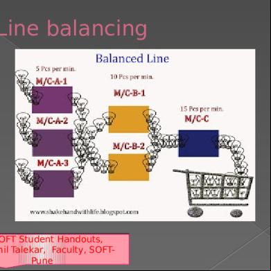
Line Balancing 12f4i
April 2021 0
Balancing Equeations 1t1v1o
July 2022 0More Documents from "Kartikkeyyan Loganathan" 5n2g2a
December 2019 43

Design Of Couplings Procedure 5z1d11
October 2019 48
Cs6304-analog And Digital Communication 2j3s6s
December 2019 48
End Feel 2s2l16
December 2019 51
Monolithic Ic-component Fabrication 5c225l
November 2019 42