Jdm A24 John Deere 1u2b4s
This document was ed by and they confirmed that they have the permission to share it. If you are author or own the copyright of this book, please report to us by using this report form. Report 2z6p3t
Overview 5o1f4z
& View Jdm A24 John Deere as PDF for free.
More details 6z3438
- Words: 1,172
- Pages: 5
. . -----
-
4q~D~4L
on~5k8b
~;q ”-=””
(m
.
. . .. .. —-,.—.. . .. ..-.
-~
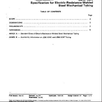
John Deere Standard
*8.
=
JDM A24 for Electric-Resistance-Welded Steel Mechanical Tubing
Specification
TABLE OF CONTENTS ,, Page SCOPE
...................................................................................
2
DESIGNATIONS
..........................................................................
2
REQUIREMENTS
..........................................................................
2
.............................................................................
5
REFERENCES ANNEX
A — Standard
ANNEX
B — Availability
—------ . .
.
Oaare
are rermmdad IFSI the mfomnehon WIS* cl 1~ ~rporal~ wlhusl & Q3(5Wny
EwnaeIIng
Information
on JDM
Steel
A2.4C and JDM
Mechanical
A24F
Tubing
Tubing
.
Fht Issued: Feb 52 Readws &wl~
Sizes of Electric-Resistance-Welded
Slandafd9
Revised: Aug 84 Superaedax Jun 69. and Ideas ctmwyad aullmrmatkm, OS@ IIMOnt
in Ilw Slawrd,
Jolwr Oaare
W
Mine,
l’ermCodtx 7960-00 os WI Ii!ids
-S IM 61265
@@ICSl
tiurnanI
CqyrI@I
itself,
C) 19S4
Design Control: DT
are the pr~rly
by Deere
& Cc+mpany
of Deere
& Company
Page: 1 of 5
This maler!a!
si?w$d co: be Lilho m U.S A.
1-
.—
.. .
M
W80J”4b”
OO05b87
8“75”h
JDM 1.
SCOPE
JDM A24 specifies the standard requirements angular, and special shape mechanical tubing of the types shown in Table 1.
of electric resistance welded steel round, square, rectmade from hot rolled or cold rolled carbon or alloy steel
JDM A24 Annex specified.
A provides
information
on sizes and shapes for which
JDM
B provides
information
on availability
2.
A24 Annex
of the newest
the dimensional
types, JDM
tolerances
A24C
are
and A24F.
DESIGNATIONS
2.1 TYPE”. The type and flash condition the JDM number shown in Table 1. 2.2 COMPOSITION. (ASTM A512 for JDM
of tubing
Example:
JDM
A24A1
2.3
THERMAL TREATMENT. If a final thermal ing the composition grade designation.
“Normalized”
is applicable
Examples: “Stress
Relieved”
Examples:
conforming
to this specification
are designated
If a specific composition is required, the grade designation A24C and A24F) is shown following the type designation.
Example:
3.
A24
JDM
to all JDM A24B3
is applicable JDM
A24B4
A24
(MT 1020
from ASTM
by
A513
(1020)
treatment
is required,
the treatment
is shown follow-
types. Normalized)
or JDM
to JDM
A24C,
A24F,
A24B4
(1 026
Stress
Relieved)
A24B3
(MT 1020
NORM)
and A24B5.
or JDM
A24B4
(1 026
SR)
REQUIREMENTS
Unless otherwise specified, the standard requirements of the latest relevant ASTM standard shall apply for all points not taken up in this JDM specification. Supplementary and special requirements, if any, shall be as specified. 3.1 CHEMICAL COMPOSITION. The heat analysis for analysis, shall be reported to the purchaser,
or the product
analysis,
and the methods
used
3.1.1 JDM A24A, A24B, A24D and A24E. The chemcial composition shall conform to ASTM A513. If no grade is specified, grades MT 1010 to MT Xl 020 or 1010 to 1026 maybe furnished at the option of the supplier. 3.1.2 JDM A24C and A24F. The chemical composition wise specified, grade 1020 shall be furnished.
-2-
shall conform
to ASTM
A512.
Unless other-
.. 4,.,., ,.,,, ,., ,, ... ,. 0005b~~ 70~ _ --.4
~
Llq/joJqb
“-n
f== ~R@’ED ; ~ SUPPLIER
TABLE JDM NUMBER
FORMER JDM NUMBER
1.
JDM
.,,.....
-
.
.
.
FOR DIST.
.
.
.
JDM
~
.
.-
A24
NUMBERS&TYPES
TYPE & FIASH CONDITION ELECTRIC RESISTANCE WELDED
STEEL MECHANICAL
TUBING
As Welded
A24A1 A24A2 A24A3’
ASTM A513 Type 1 As Welded from Hot Rolled Steel, A. W.H.R. ● Flash-in ● Flash Controlled to 0.25 mm (0.01 O in) Max . Flash Controlled to 0.13 mm (0.005 in) Max
A24B1 A24B2 A24B3 A24B3A
ASTM A513 Type 2 As ● Flash-In . Flash Controlled to ● Flash Controlled to ● (Special) No Flash, Sink Drawn
(Drawn
Welded
from Cold Rolled Steel, A. W.C.R.
0.25 mm (0.01 O in) Max 0.13 mm (0.005 in) Max Free from Weld Spatter
without
Mandrel)
Normalized & Sink Drawn conforming to ASTM A5~ 2 except for electric resistance weld and mechanical properties
A24C
A24D1 A24D2 A24D3
A24AI C A24A2C A24A3C
ASTM A513 Type 3 Sink Drawn from Hot Rolled Steel, ● Flash-In ● Flash Controlled to 0.25 mm (0.01 O in) Max . Flash Controlled to 0.13 mm (0.005 in) Max
A24E1 A24E2 A24E3
A24B1 C A24B2C A24B3C
ASTM A513 Type 4 Sink Drawn from Cold Rolled Steel, ● Flash-In ● Flash Controlled to 0.25 mm (0,01 O in) Max ● Flash Controlled to 0.13 mm (0.005 in) Max Mandrel
Drawn
(Drawn
Outside
Normalized for electric
A24B4
ASTM
Type 5 Mandrel
Drawn,
M.D.
A24B5
ASTM A513 Type”6 Mandrel Diameter, S. S.I.D.
Drawn,
Special
NOTE:
A513
S. D.H.R.
S. D.C.R.
& Inside — No Flash)
A24F
& Mandrel Drawn conforming to ASTM A~l 2 except resistance weld and mechanical properties
a. See 3.3.2
-3-
Smooth
Inside
.
.
. .
.
.
.. .
ES
47190J9h
.
0005L87
.
hqd
ii
.
3.
3,2
JDM
REQUIREMENTS THERMAL
A24
-
(continued)
TREATMENT
3.2.1 JDM A24A, A24B, A24D with no final thermal treatment. 3.2.2 JDM A24C or stress relieved. 3.3 MECHANICAL required mechanical
and A24F.
and A24E.
Unless
Unless
otherwise
otherwise
specified,
specified,
the tubing
the tubing is to be furnished
may be furnished
PROPERTIES OF ROUND TUBING. The test data and the methods properties shall be reported to the purchaser.
unannealed
of testing
for
3.3.1 JDM A24A, A24B, A24D and A24E. Round tubing with specified composition grade shall conform to the tensile requirements (and not necessarily the hardness limits) shown in ASTM A513 for the specified type, grade, and condition. 3.3.2 JDM A24C and A24F. Grade 1020 round tubing, either meet or exceed the following minimum mechanical properties. Tensile Strength Yield Strength (0.2% offset) Elongation in 50 mm (2 in)
485 MPa 415 MPa 1 o%
3.4 ENDS OF ROUND TUBING. Unless otherwise within the tolerance for squareness of cut specified one end. 3.5
DIMENSIONAL
(70000 (60000
unannealed
or stress relieved,
shall
psi) psi)
specified, round tubing shall have square cut ends in ASTM A513, and shall have burrs removed from
TOLERANCES
3.5.1 JDM A24A, A24B, A24D and A24E. Round, square and rectangular tubing shall conform to the permissible variations in dimensions specified in ASTMA513. For round JDM A24A or A24B tubing with specified intermediate wall thickness, the wall thickness tolerance shown for the next thicker standard wall shall apply. For special shape tubing, and for tubing outside the size range specified in ASTM A513, the dimensional limits shall be as agreed between the purchaser and the supplier, 3.5.2 JDM A24C and A24F. Round, square and rectangular tubing shall conform to the permissible variations in dimensions specified in ASTM A512. For special shape tubing, the dimensional limits shall be as agreed between the purchaser and the supplier. 3.6 PROTECTIVE COATING. Unless otherwise s~ecified, the tubing shall be coated to prevent exThe coating shall be removable by an cessive rusting for 100 hours when tested per ASTM D1 748. alkaline or organic solvent cleaner.
4.
REFERENCES ASTM
A512
Standard Tubing
ASTM
A513
Standard Specification Mechanical Tubing
ASTM
D1 748
Test Method for Rust Protection
Specification
for Cold Drawn
Butt Weld
Carbon
for Electric-Resistance-Welded
by Metal
Preservatives
Steel
Mechanical
Carbon and Alloy Steel
in the Humidity
Cabinet
-5-
.
I
-
4q~D~4L
on~5k8b
~;q ”-=””
(m
.
. . .. .. —-,.—.. . .. ..-.
-~
John Deere Standard
*8.
=
JDM A24 for Electric-Resistance-Welded Steel Mechanical Tubing
Specification
TABLE OF CONTENTS ,, Page SCOPE
...................................................................................
2
DESIGNATIONS
..........................................................................
2
REQUIREMENTS
..........................................................................
2
.............................................................................
5
REFERENCES ANNEX
A — Standard
ANNEX
B — Availability
—------ . .
.
Oaare
are rermmdad IFSI the mfomnehon WIS* cl 1~ ~rporal~ wlhusl & Q3(5Wny
EwnaeIIng
Information
on JDM
Steel
A2.4C and JDM
Mechanical
A24F
Tubing
Tubing
.
Fht Issued: Feb 52 Readws &wl~
Sizes of Electric-Resistance-Welded
Slandafd9
Revised: Aug 84 Superaedax Jun 69. and Ideas ctmwyad aullmrmatkm, OS@ IIMOnt
in Ilw Slawrd,
Jolwr Oaare
W
Mine,
l’ermCodtx 7960-00 os WI Ii!ids
-S IM 61265
@@ICSl
tiurnanI
CqyrI@I
itself,
C) 19S4
Design Control: DT
are the pr~rly
by Deere
& Cc+mpany
of Deere
& Company
Page: 1 of 5
This maler!a!
si?w$d co: be Lilho m U.S A.
1-
.—
.. .
M
W80J”4b”
OO05b87
8“75”h
JDM 1.
SCOPE
JDM A24 specifies the standard requirements angular, and special shape mechanical tubing of the types shown in Table 1.
of electric resistance welded steel round, square, rectmade from hot rolled or cold rolled carbon or alloy steel
JDM A24 Annex specified.
A provides
information
on sizes and shapes for which
JDM
B provides
information
on availability
2.
A24 Annex
of the newest
the dimensional
types, JDM
tolerances
A24C
are
and A24F.
DESIGNATIONS
2.1 TYPE”. The type and flash condition the JDM number shown in Table 1. 2.2 COMPOSITION. (ASTM A512 for JDM
of tubing
Example:
JDM
A24A1
2.3
THERMAL TREATMENT. If a final thermal ing the composition grade designation.
“Normalized”
is applicable
Examples: “Stress
Relieved”
Examples:
conforming
to this specification
are designated
If a specific composition is required, the grade designation A24C and A24F) is shown following the type designation.
Example:
3.
A24
JDM
to all JDM A24B3
is applicable JDM
A24B4
A24
(MT 1020
from ASTM
by
A513
(1020)
treatment
is required,
the treatment
is shown follow-
types. Normalized)
or JDM
to JDM
A24C,
A24F,
A24B4
(1 026
Stress
Relieved)
A24B3
(MT 1020
NORM)
and A24B5.
or JDM
A24B4
(1 026
SR)
REQUIREMENTS
Unless otherwise specified, the standard requirements of the latest relevant ASTM standard shall apply for all points not taken up in this JDM specification. Supplementary and special requirements, if any, shall be as specified. 3.1 CHEMICAL COMPOSITION. The heat analysis for analysis, shall be reported to the purchaser,
or the product
analysis,
and the methods
used
3.1.1 JDM A24A, A24B, A24D and A24E. The chemcial composition shall conform to ASTM A513. If no grade is specified, grades MT 1010 to MT Xl 020 or 1010 to 1026 maybe furnished at the option of the supplier. 3.1.2 JDM A24C and A24F. The chemical composition wise specified, grade 1020 shall be furnished.
-2-
shall conform
to ASTM
A512.
Unless other-
.. 4,.,., ,.,,, ,., ,, ... ,. 0005b~~ 70~ _ --.4
~
Llq/joJqb
“-n
f== ~R@’ED ; ~ SUPPLIER
TABLE JDM NUMBER
FORMER JDM NUMBER
1.
JDM
.,,.....
-
.
.
.
FOR DIST.
.
.
.
JDM
~
.
.-
A24
NUMBERS&TYPES
TYPE & FIASH CONDITION ELECTRIC RESISTANCE WELDED
STEEL MECHANICAL
TUBING
As Welded
A24A1 A24A2 A24A3’
ASTM A513 Type 1 As Welded from Hot Rolled Steel, A. W.H.R. ● Flash-in ● Flash Controlled to 0.25 mm (0.01 O in) Max . Flash Controlled to 0.13 mm (0.005 in) Max
A24B1 A24B2 A24B3 A24B3A
ASTM A513 Type 2 As ● Flash-In . Flash Controlled to ● Flash Controlled to ● (Special) No Flash, Sink Drawn
(Drawn
Welded
from Cold Rolled Steel, A. W.C.R.
0.25 mm (0.01 O in) Max 0.13 mm (0.005 in) Max Free from Weld Spatter
without
Mandrel)
Normalized & Sink Drawn conforming to ASTM A5~ 2 except for electric resistance weld and mechanical properties
A24C
A24D1 A24D2 A24D3
A24AI C A24A2C A24A3C
ASTM A513 Type 3 Sink Drawn from Hot Rolled Steel, ● Flash-In ● Flash Controlled to 0.25 mm (0.01 O in) Max . Flash Controlled to 0.13 mm (0.005 in) Max
A24E1 A24E2 A24E3
A24B1 C A24B2C A24B3C
ASTM A513 Type 4 Sink Drawn from Cold Rolled Steel, ● Flash-In ● Flash Controlled to 0.25 mm (0,01 O in) Max ● Flash Controlled to 0.13 mm (0.005 in) Max Mandrel
Drawn
(Drawn
Outside
Normalized for electric
A24B4
ASTM
Type 5 Mandrel
Drawn,
M.D.
A24B5
ASTM A513 Type”6 Mandrel Diameter, S. S.I.D.
Drawn,
Special
NOTE:
A513
S. D.H.R.
S. D.C.R.
& Inside — No Flash)
A24F
& Mandrel Drawn conforming to ASTM A~l 2 except resistance weld and mechanical properties
a. See 3.3.2
-3-
Smooth
Inside
.
.
. .
.
.
.. .
ES
47190J9h
.
0005L87
.
hqd
ii
.
3.
3,2
JDM
REQUIREMENTS THERMAL
A24
-
(continued)
TREATMENT
3.2.1 JDM A24A, A24B, A24D with no final thermal treatment. 3.2.2 JDM A24C or stress relieved. 3.3 MECHANICAL required mechanical
and A24F.
and A24E.
Unless
Unless
otherwise
otherwise
specified,
specified,
the tubing
the tubing is to be furnished
may be furnished
PROPERTIES OF ROUND TUBING. The test data and the methods properties shall be reported to the purchaser.
unannealed
of testing
for
3.3.1 JDM A24A, A24B, A24D and A24E. Round tubing with specified composition grade shall conform to the tensile requirements (and not necessarily the hardness limits) shown in ASTM A513 for the specified type, grade, and condition. 3.3.2 JDM A24C and A24F. Grade 1020 round tubing, either meet or exceed the following minimum mechanical properties. Tensile Strength Yield Strength (0.2% offset) Elongation in 50 mm (2 in)
485 MPa 415 MPa 1 o%
3.4 ENDS OF ROUND TUBING. Unless otherwise within the tolerance for squareness of cut specified one end. 3.5
DIMENSIONAL
(70000 (60000
unannealed
or stress relieved,
shall
psi) psi)
specified, round tubing shall have square cut ends in ASTM A513, and shall have burrs removed from
TOLERANCES
3.5.1 JDM A24A, A24B, A24D and A24E. Round, square and rectangular tubing shall conform to the permissible variations in dimensions specified in ASTMA513. For round JDM A24A or A24B tubing with specified intermediate wall thickness, the wall thickness tolerance shown for the next thicker standard wall shall apply. For special shape tubing, and for tubing outside the size range specified in ASTM A513, the dimensional limits shall be as agreed between the purchaser and the supplier, 3.5.2 JDM A24C and A24F. Round, square and rectangular tubing shall conform to the permissible variations in dimensions specified in ASTM A512. For special shape tubing, the dimensional limits shall be as agreed between the purchaser and the supplier. 3.6 PROTECTIVE COATING. Unless otherwise s~ecified, the tubing shall be coated to prevent exThe coating shall be removable by an cessive rusting for 100 hours when tested per ASTM D1 748. alkaline or organic solvent cleaner.
4.
REFERENCES ASTM
A512
Standard Tubing
ASTM
A513
Standard Specification Mechanical Tubing
ASTM
D1 748
Test Method for Rust Protection
Specification
for Cold Drawn
Butt Weld
Carbon
for Electric-Resistance-Welded
by Metal
Preservatives
Steel
Mechanical
Carbon and Alloy Steel
in the Humidity
Cabinet
-5-
.
I
Related Documents c2h70
Jdm A24 John Deere 1u2b4s
October 2019 92
John Deere 695n2f
April 2023 0
John Deere 695n2f
November 2022 0
Motores John Deere 6w5i53
February 2021 0
Lubricantes - John Deere qf57
March 2021 0