Fan Regulator Technology 3j25g
This document was ed by and they confirmed that they have the permission to share it. If you are author or own the copyright of this book, please report to us by using this report form. Report 2z6p3t
Overview 5o1f4z
& View Fan Regulator Technology as PDF for free.
More details 6z3438
- Words: 1,339
- Pages: 3
DEKI CAPACITOR GUIDE
Fan Regulators FAN REGULATOR A Fan Regulator, as the name suggests, regulates or controls the speed of the fan motor. Before dealing with the fan regulator, a brief discussion about the fan motor is necessary, as the main purpose of the regulator is to control the speed of the fan motor.
PURPOSE OF RUNNING CAPACITOR A capacitor is incorporated in circuit so that IS and IM are 90° apart in phase from each other (ideal case) so that a revolving or rotating magnetizing flux can be set up.
STARTING OF FAN When the supply is given a rotating flux is set up in the stator which is revolving with synchronous speed NS. NS = (120*f) / p f = supply frequency p = number of poles CONSTRUCTIONAL FEATURES This flux induces a voltage in the rotor due to electromagnetic A 1φ induction motor employs two windings for its operation as induction. As this rotor is initially stationary, torque is developed it is not a self-starting version of an induction motor (polyphase which rotates the rotor and rotor speed starts to build up. The motor). The two windings are main/running winding and direction of rotation is the same as that of the rotating flux. The starting/auxiliary winding. The windings are placed on a torque developed is given by 2 stationary member called stator, that has stampings and slots to TµSV hold the windings. S = slip speed Now, this torque is proportional to square of voltage. 2 The rotor is the rotating member, of a squirrel cage type, on Speed µ Torque µ V which the fan blades are mounted. Hence, by controlling the voltage supply across the fan its speed can be varied. Note: It also incorporates a capacitor in series with a starting winding. TYPES OF FAN REGULATORS Currently Fan Regulators are of these four types: PRINCIPLE OF OPERATION ? Resistive regulator A ceiling fan motor is based on Faraday’s Law of Electro-magnetic ? Phase angle controlled regulator Induction according to which whenever a conductor is placed in a ? Inductive regulator rotating magnetic field, an electro-magnetic force (emf) is ? Capacitive regulator (latest). induced. The frequency of the induced emf is the same as the supply frequency and its magnitude is proportional to the relative RESISTIVE REGULATOR motion between the flux and the conductor. The direction of the This is the most common type in household ceiling fans. It induced emf is given by Fleming’s Right Hand Rule. works by providing different taps on a wire wound resistor connected in series with the fan. WORKING In order to make a ceiling fan self-starting, a starting or auxiliary winding is used, placed electrically 90° apart from the main winding, with a running capacitor in series with the starting winding. Both the windings are connected in parallel to each other. Winding supply across the terminal as shown in the figure. FAN MOTOR The motor used in a household ceiling fan is a 1φ squirrel cage type induction motor with the properties and specifications of a normal 1φ motor.
Advantages ? Cost-effective. Disadvantages ? Considerable power loss as heat, especially at lower speeds, making it inefficient ? Bulky, lack of aesthetic appeal ? Very high energy consumption.
Fig: Capacitor Run Fan Motor 4
DEKI CAPACITOR GUIDE
Fan Regulators PHASE ANGLE CONTROLLED REGULATOR Phase angle controlled regulators employ active devices such as DIAC and TRIAC. The basic principle is to change the firing angle of the TRIAC in order to change the voltage across the fan.
CAPACITIVE TYPE FAN REGULATOR
0.1/250 V/10%
0.01/1k V/10%
Advantages ? Continuous speed control ? Low power consumption as compared to resistive type regulators. Disadvantages ? Speed control not linear ? Expensive as compared to resistive fan regulators. ? Produces humming sound that is disturbing ? Higher failure rate as active devices are susceptible to power supply transients and interference ? Causes EMI/RFI interference creating disturbances in TV and radio sets. INDUCTIVE TYPE FAN REGULATOR An inductive type fan regulator has a tapping on the winding of the transformer and the inductive reactance is varied to achieve variation in speed.
Basic Principle The main purpose here is to control the voltage acrossthe fan. As we know, the voltage across the capacitor is given by the formula VC = Q/C where Q is the charge across the capacitor and C is the capacitance. According to the formula above, C µ 1/VC. As C increases VC decreases. Thus, the voltage across the fan increases. Therefore, the speed increases. So, by increasing the value of capacitor, the speed of the fan can be increased. Thus, by employing suitable combinations of capacitors a fan’s speed can be regulated. Purpose of RS and RP RS is a series resistance which is used in series with the capacitor in order to limit the current flowing to the capacitor to a safe value. RP is a parallel resistance which serves as a discharging path for the capacitor for each supply cycle.
CAPACITIVE FAN REGULATOR - BLOCK DIAGRAM
NOTE: Speed decreases with the increase in the number of turns of the inductance coil winding.
CAPACITIVE FAN REGULATOR - CIRCUIT DIAGRAM
Advantages Low heat power dissipation.
?
Disadvantages Low power factor. Quite costly. Heavy and bulky.
? ? ?
5
DEKI CAPACITOR GUIDE
Fan Regulators How to calculate the value of the capacitors
EXPERIMENTAL STUDY Fans from different manufacturers are tested on a standard regulator with combinations of 2.2, 1.0 and 3.1 µF. Now, At speed 1 = 2.2 µF At speed 2 = 3.1 µF At speed 3 = 4.1 µF At speed 4 = 5.3 µF At speed 5 = no capacitor
Applying KVL (Kirchof’s voltage law), the calculated value of XC is For, Fan A, maximum RPM = 320 given by (VS × ZF – VF × ZF) / VF = XC Fan B, maximum RPM = 422 where, VS = supply voltage Fan C, maximum RPM = 380 VF = voltage across the fan ZF = impedance of the fan, Configurations at various switch positions and, the value of capacitance can be calculated by Position 1 C= 1 / (2 × π × f × XC) where, f is the supply frequency. Advantages ? Energy efficient ? No humming sound during operations ? Speed is linear ? High reliability as compared to electronic type regulator. Disadvantages ? Becaues of size only marginal design is possible for film capacitor ? Fire hazard is, hence, the only failure mode.
At this position, capacitor in the circuit = 2.2 µF. 16.
Position 2
Let us examine the ISI standards for fan regulators as per IS:374-1979: ? Regulators including electronic type of speed regulators shall be capable of reducing the speed of the fan at least 50 per cent of the full speed at the test voltage. ? Fans shall be capable of running on all the running positions of the regulator at the rated voltage or within the whole rated voltage range. ? Shall have an ‘OFF’ position preferably next to the lowest speed . At this position, capacitor in the circuit = 3.1 µF. ? Shall be provided with not less than five running positions except in case of continuously variable speed regulators. Position 3 ? The speed difference at any running position shall not deviate by more than +/- 50 % from the ideal speed difference calculated on the basis of maximum and minimum speeds divided by the number of steps. Max speed of the fan: 400 rpm Min speed of the fan: 200 rpm Regulator steps: 5 Ideal speed difference = 200/5 = 40 rpm ? Speed difference between any two running positions ? should be between 20 and 60 rpm. ? Electronic type regulators shall be provided with radio ? and television interference suppressing devices. At this position, capacitor in the circuit = 3.1 + 1 = 4.1 µF. ? The voltage drop across the electronic type regulators at ? the maximum speed position shall not exceed 2% of the ? rated voltage of the fan. 6
Related Documents c2h70

Fan Regulator Technology 3j25g
November 2019 56
Fan Regulator 5h693v
December 2019 60
Remote Controlled Fan Regulator y6j5v
November 2019 72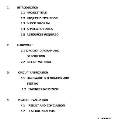
Remote Control Fan Regulator 5n3x1s
November 2019 53
Remote Controlled Fan Regulator y6j5v
December 2019 42
Fan Regulator Energy Savings 350o
December 2019 52More Documents from "Aubrey Holt" 5y2b2q

Lean Library 3p1yv
November 2019 83
Fan Regulator Technology 3j25g
November 2019 56
Fan Regulator Energy Savings 350o
December 2019 52
Control Charts And Process Control In Sap 221626
November 2019 46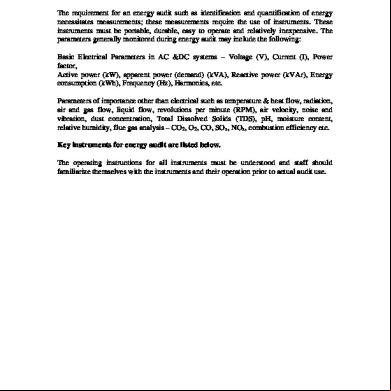
Energy Audit Instruments 696f39
December 2019 46