Erico System 3000 y3h29
This document was ed by and they confirmed that they have the permission to share it. If you are author or own the copyright of this book, please report to us by using this report form. Report 2z6p3t
Overview 5o1f4z
& View Erico System 3000 as PDF for free.
More details 6z3438
- Words: 4,695
- Pages: 12
ERITECH® SYSTEM 3000 Lightning Protection Products
Centrepoint Tower, Sydney, Australia
Central Plaza, Hong Kong, P.R. China
Skytower, Aukland, New Zealand
Lightning can be devastating. Besides the danger to people, it is a major cause of expensive electronic equipment failure and costly business disruption. In general, the highest point of a facility is the most vulnerable to a direct lightning strike. Lightning rods or air terminals are needed to capture the strike to a preferred point and to safely conduct the energy to ground to minimize the risk. ERICO has developed the ERITECH SYSTEM 3000 advanced lightning protection system. This innovative system has been used in over 15,000 installations around the world. The Skytower in Auckland New Zealand is an example of the suitability of the system for a wide variety of structure types. ®
®
On July 21st, 1999, the ERITECH SYSTEM 3000 ERITECH® DYNASPHERE captured as many as 16 lightning strikes to the Skytower in a period of 30 minutes during a fierce thunderstorm. Video footage of this spectacular event shows the ERITECH DYNASPHERE capturing the lightning strike. As the lightning bolt approaches the tower, the ERITECH DYNASPHERE can be seen to launch a continuous upward leader to intercept the approaching lightning bolt (downward leader). The Bank of China in Hong Kong has been protected by the ERITECH SYSTEM 3000® from more than 100 direct strikes since 1989. Mt. Tangkuban Perahu Communications Tower in West Java, Indonesia, installed the ERITECH® SYSTEM 3000 and has experienced 56 lightning strikes over a period of 3 years without damage or downtime. The ERITECH SYSTEM 3000 installed on the Centerpoint Tower, Sydney has recorded more than 40 strikes since November 1995 and the Central Plaza, Hong Kong has been protected from more than 20 lightning strikes since the installation of the system.
LIGHTNING STRIKES again and again and again... ERITECH® SYSTEM 3000 ERITECH® DYNASPHERE Air Terminals
ERICO® is dedicated to providing the best lightning-protection solution for any given application, whether this involves the use of the standards compliant ERITECH® SYSTEM 2000, the ERITECH® SYSTEM 3000 or a hybrid design utilizing a combination of both system types. ERICO manufactures lightning Various Air Terminals protection systems in full accordance with more than twelve national and international standards, as well as non-conventional systems based on enhanced air terminals and insulated conductors for applications where these provide an advantageous solution for the customer. ERICO’s approach is solutions driven. The aim is to provide the best solution for a given application. Some structures are more suited to the traditional conventional lightning protection – designs that require protection via complete building structure bonding. Other structures are more suited to a method that utilizes protection via isolation. Whatever the application or protection problem presented, ERICO offers a solution.
2
www.erico.com
ERITECH® SYSTEM 3000 What is the ERITECH® SYSTEM 3000? The ERITECH® SYSTEM 3000 is a technically advanced lightning protection system. The unique features of this system allow the achievement of reliable lightning capture and control. The ERITECH® DYNASPHERE air terminal provides a preferred point for lightning discharges which would otherwise strike and damage an unprotected structure and/or its contents. The ERITECH® DYNASPHERE is optimally connected to an ERITECH® ERICORE downconductor and low impedance grounding system in such a way as to provide a totally integrated system. ERITECH SYSTEM 3000 includes the following elements: • ERITECH® DYNASPHERE air terminal • ERITECH® ERICORE downconductor • Lightning event counter • Purpose designed low impedance grounding system. These components form an integral part of the ERICO® Six Point Plan of Protection. Each component must be considered independently and ultimately integrated together to form the complete lightning protection system. Without such integration there is limited protection. While it is possible to implement a hybrid system using other components, it is important to realize that inefficiencies in any substitute represents an inefficiency in the protection system as a whole.
Lightning Down Leader Upleader ERITECH DYNASPHERE Terminal F.R.P. Inline Coupling Stainless Steel Cable Tie Metallic Lower Mast
Mounting Brackets ERITECH ERICORE Downconductors
Downconductor Saddle
Lightning Event Counter Inspection Pit
Grounding Rods
www.erico.com
There is no known method of preventing the occurrence of a lightning discharge. The purpose of a lightning protection system therefore, is to control the age of a discharge in such a manner that prevents personal injury or property damage. The need to provide protection should be assessed in the early stages of the structure design.
1. The Air Terminal The primary function of an air terminal, or air termination system, is to capture the lightning strike to a preferred point, so that the discharge current can be directed via the downconductor(s) to the grounding system. 2. The Downconductor The function of a downconductor is to provide a low impedance path from the air termination to the ground system so that the lightning current can be conducted to earth, without the development of excessively large voltages. In order to reduce the possibility of dangerous sparking (side-flashing), the downconductor route(s) should be as direct as possible with no sharp bends or stress points where the inductance, and hence impedance, is increased under impulse conditions. 3. The Grounding System The grounding system must have a low impedance to disperse the energy of the lightning strike. Because the lightning discharge consists of high frequency components, we are particularly concerned with the frequency-dependent electrical parameter of a grounding system – impedance – as well as low resistance grounding. Grounding systems are highly variable from site to site due to geographical considerations. The grounding grid should minimize the ground voltage potential rise and minimize the risk of injury to personnel or damage to equipment.
3
ERICO® Involvement in Lightning Protection Research ERICO® has investigated the lightning protection process through years of research involving long term field studies. Laboratory testing, using some of the largest outdoor test laboratories, and countless research study programs, including t ventures with accomplished scientists in the field have also been used in the research process. This extensive research has resulted in some of the most up-todate published technical papers and journals. ERICO is committed to the development of a range of lightning protection standards around the world. The ERITECH® SYSTEM 3000 has evolved from this research activity, with earlier versions of the ERITECH SYSTEM 3000 providing a building block for the latest advancements through extensive field studies, leading edge indoor and outdoor high voltage testing and computer modeling research . ERICO is involved in the lightning protection industry in many countries around the world and acknowledges the diverse protection methods that exist today.
LONG-TERM STUDIES DEMONSTRATE THE EFFECTIVENESS OF ERITECH® SYSTEM 3000 ERICO has conducted two unprecedented, long-term field-validation studies of the Collection Volume Method of lightning protection with the ERITECH SYSTEM 3000 lightning-protection system. The Collection Volume Method (CVM), also known as Eriksson’s Attractive Radius Model, defines the lightning “capture volume” of potential strike points on a structure. CVM considers the physical criteria for air breakdown together with a knowledge of the electric field intensification created by different points on a structure. The first study, conducted from 1988 through 1996 in Hong Kong, demonstrated that it is possible to dimension the interception efficiency or performance of a lightning protection system using real field data. This method circumvents the problems associated with laboratory testing, where scale-size issues are difficult to resolve and faithful replication of the electric field wavefronts observed in nature can be troublesome.
4
www.erico.com
ERITECH® SYSTEM 3000 The number of strikes to the protection system of the structures in this study were obtained from “lightning event counters” (LEC) placed around the lightning current downconductor cable. Overall, estimates of the strike “yield” demonstrate that the interception rate predicted by the CVM is in excellent agreement with the observed capture frequency. This means that the lightning-interception rate is at least as high as the claimed protection levels, which lie in the 85 – 98% range. The second study, conducted from 1990 through 2000 in Malaysia, quantified interception efficiency. The study consisted of a statistically valid sample of buildings mainly in the Klang Valley region of Kuala Lumpur. The 47 sites had between 1 and 5 buildings per site with a mean structure height of 58 m (190 ft). The mean actual protection level was 78%, confirming that up to 22% of low-intensity flashes under 10 kA could by the lightning protection system (LPS). Mitigating factors such as budget constraints and subsequent changes to the structures (e.g. the addition of antennas and extensions) impacted the initial design and prevented the protection level from being higher. At the end of the study, the actual interception efficiency was 86%, ten percent better than predicted. Both of these long-term field studies are now published in independently peer-reviewed scientific journal publications.
ERITECH® SYSTEM 3000 ed by Collection Volume Method Placement The placement of air terminals on structures is often performed with the Rolling Sphere Method (RSM), which is based on the simple Electro Geometric Model (EGM) for striking distance. The simple EGM does not for the physical basis of the upward leader inception process and the importance of the structure height or the geometry of objects on the structure. The RSM uses a fixed striking distance, typically 45 m, irrespective of the structure height or width. This means that a structure of height 5 m is assigned the same capture area and strike probability as a 100 m communications tower. An improved electro geometric model was initially developed by Dr A.J. Eriksson (1979, 1980, 1987). Beginning in the late 1980’s, Eriksson’s basic model was extended by ERICO® scientists and engineers for application to practical structures. This has been done through computer modeling of electric fields around a wide range of 3D structures and by application of the concept of “competing features,” to determine whether a structure is protected. This new method has been known worldwide for many years as the Collection Volume Method (CVM). The CVM considers the physical criteria for air breakdown, together with a knowledge of the electric field intensification created by different points on a structure. CVM then uses this information to provide the optimum lightning protection system for a structure, i.e., the most efficient placement of air terminals for a selected protection level. Using the modern risk management approach, the CVM output depends on -selected protection levels. Typical protection levels are in the range 84-99%. These values are taken from a standard distribution of peak lighting stroke currents.
Design The placement and application of the ERITECH® SYSTEM 3000 is critical to ensure optimal protection is provided. ERICO’s unique computer aided design program enables easier, reliable application of the ERITECH SYSTEM 3000, taking into individual site parameters and the variables required to complete an optimal design using the CVM. Please your nearest ERICO® office for applications engineering .
www.erico.com
5
Strike 1
2 Coulomb
Strike 2
1 Coulomb 3 Coulomb
A
B
The Collection Volume Method defines the lightning “capture volume” of potential strike points on a structure. This method is used in conjunction with the ERITECH® SYSTEM 3000 lightning protection system but is equally applicable for the placement of conventional terminals.
The ERITECH® DYNASPHERE Enhanced Air Terminal
ERITECH® DYNASPHERE Air Terminal During the dynamic phase of the thunderstorm, on closer approach of the downward leader, the semi-sphere or dome of the ERITECH® DYNASPHERE will rise in voltage via capacitive coupling. When the voltage is high enough, a triggering arc is created across the air gap between the sphere and grounded rod.
The patented ERITECH® DYNASPHERE is an enhanced air terminal. Features include: • Non-radioactive technology • No external power required
The triggering arc has two effects: (i) it produces the large number of free electrons needed to initiate an upward streamer (ii) it causes a sudden “snap” increase in the electric field above the air terminal, which provides the additional energy to initiate and convert a strong propagating upward leader.
• No moving parts • Selection of tip radii and variable impedance to adjust for optimum performance at different installation heights • Dynamic response to the approach of a lightning downleader
These two effects develop stable leader propagation to help ensure reliable lightning capture. The size of the air gap is optimized so that a triggering arc only occurs when the ambient electric field is high enough to ensure a stable upward leader can be developed to successfully intercept the downward leader.
Principles of the ERITECH DYNASPHERE For more than 200 years, little improvement was made in lightning protection systems. However, modern research and recording methods have led to an improved understanding of the lightning discharge process, and various advancements have been achieved in the simulation of lightning electric-field conditions. Two fundamental concepts have emerged from these advancements in the lightning attachment process and air terminal performance: • Air terminals that produce copious quantities of corona (space charge) are less efficient strike receptors. • An optimum air terminal is one which launches an upward streamer when the ambient electric field is at a level to the continual propagation of the leader. The ERITECH DYNASPHERE has been developed with these two concepts in mind. The ERITECH DYNASPHERE is an enhanced Franklin rod with a semi-spherical dome which is capacitively coupled to the electric field of an approaching lightning downleader. This spherical conductive dome surrounds a central earthed lightning rod. The dome is insulated from the rod but connected to ground via a dynamic variable impedance with DC conduction. The ERITECH DYNASPHERE is isolated from the structure using an insulated mast. The mast also helps enable the safe connection of the ERITECH® ERICORE downconductor to the air terminal.
Static Thunderstorm Phase
Dynamic Thunderstorm Phase
Controlled Triggering Streamer Phase
The ERITECH DYNASPHERE has been designed to meet the criteria necessary for the controlled emission of a streamer. The concept of "controlled" is important because it is not effective to launch a streamer too early – the ambient field will not be large enough to convert the streamer to a leader and so the streamer will cease to propagate. This will leave a space charge behind which can inhibit future initiation attempts.
Characteristics of an optimum air terminal: • Minimal pre-strike corona / space charge. • Streamers released only when the ambient field can sustain leader initiation and propagation. Both of these characteristics require a blunt configuration. The ERITECH DYNASPHERE Enhanced Air Terminal Capture point of the ERITECH SYSTEM 3000 initiates an upward leader during thunderstorm conditions.
ERITECH DYNASPHERE MKIV complete with ERITECH ERICORE assembled.
6
www.erico.com
ERITECH® System 3000
Various mounting options.
The ERITECH® INTERCEPTOR Air Terminal is specifically designed for smaller installations that do not require the larger protection radius offered by the ERITECH® DYNASPHERE. The ERITECH INTERCEPTOR is based on similar technology to the ERITECH® DYNASPHERE, but its smaller shape limits its applications to those structures with a smaller footprint such as a cluster of antennae or those that are less than 20 m tall (65 ft).
The ERITECH® INTERCEPTOR MKIV.
As the ERITECH INTERCEPTOR tip is limited to small areas or structures under 20 m tall, it is supplied with one standard tip shape. Various mounting arrangements for the ERITECH® INTERCEPTOR are shown below:
ERITECH INTERCEPTOR
ERITECH INTERCEPTOR INTMKIV-SS
ERITECH INTERCEPTOR INTMKIV-SS
INTT-3/4UNC
INTT-ADF2NPS OR INTT-ADFSBSPF
CONDUCTIVE MAST
www.erico.com
ERITECH INTERCEPTOR INTMKIV-SS
ERITECH INTERCEPTOR INTMKIV-SS
INTT-ADBUTT MAST BUTT ADAPTER
INTT-ADBUTT MAST BUTT ADAPTER
LOCK SCREW ERITECH® ERICORE UPPER TERMINATION
LOCK SCREW TERMLUGCOUP CONVENTIONAL DOWNCONDUCTOR
FRP MAST
FRP MAST
2" PIPE
7
ERITECH® ERICORE Downconductor The ERITECH ERICORE Downconductor As an integral part of the ERITECH® SYSTEM 3000, the screened, insulated ERITECH ERICORE® downconductor conveys the lightning discharge current to ground with minimal danger of sideflashing. A unique semi-conductive outer sheath allows electrostatic bonding of the building through cable securing saddles. The ERITECH ERICORE downconductor evolved after extensive studies of potential voltage rise in structures due to lightning injection. This cable is comprised of carefully selected dielectric materials, which create capacitive balance and help ensure insulation integrity under high impulse conditions. The unique ability of ERITECH ERICORE to confine a discharge current and simultaneously electrical bonding helps ensure minimal risk to building, occupants and sensitive electronics. Cutaway diagram showing the composite layers of ERITECH ERICORE Downconductor. Inset: ERITECH ERICORE upper termination.
350
Technical and Design Characteristics of ERITECH® ERICORE
250 Voltage (kV)
The ERITECH® ERICORE downconductors have been designed to meet criteria for an effective and reliable downconductor, with the following key characteristics: • low inductance per unit length • low surge impedance • carefully controlled internal electric field distribution to minimize field stresses under current impulse conditions • carefully designed, stress reducing upper termination
(3)
(4)
(1)
100 (2)
0
30
60
90
120
Length (m)
Type % less Discharge than 1 2 3 4
-ve +ve -ve +ve
50 50 95 95
Waveshape (μs) 5.5/75 22/230 1.8/30 3.5/25
di/dt (max) (kA/μs)
Peak Current (kA)
24.3 2.4 65.0 32.0
70.1 28.7 51.9 59.1
Statistics taken from IEC 62305 Part 1.
The ERITECH ERICORE Downconductor is easily retrofitted to existing structures. Inset: ERITECH® Lightning Event Counter (LEC IV) installed to strikes to ERITECH® SYSTEM 3000.
To understand the technical value of the cable, it is first necessary to review the problems associated with normal downconductors. A value of inductance of 1.6 μH/m is normally regarded as quite small. However, when a current is impressed which is rising at the rate of 1010 Amperes per second, the effect of this inductance becomes dominant. As an example, a single 60 meter downconductor will rise to a value in excess of 1,000,000 volts with the application of an average discharge. It is for this reason that the ERITECH ERICORE downconductor has a significant advantage over conventional downconductors.
8
www.erico.com
ERITECH® ERICORE DOWNCONDUCTOR Typical Lightning Waveform Stage 1 - Impedance (Z) Z0 = √
L C
Cable voltage determined by Z0
Current (A)
Stage 2 - Inductance (L) V ∝ L dl Cable voltage determined by dt
inductance and its rate of change
Stage 3 - Resistance (R) IR. Time (t) Stage 1 Z0 dominant
Stage 2 L dominant
Stage 3 R dominant
Cable voltage determined by L&R but L is small or negative due to small dI/dt. Summary of the three main stages of ERTIECH ERICORE operation
ERITECH® ERICORE offers purpose-designed performance in each phase of the lightning control process to help convey the energy safely to the grounding system. As an example, consider the following comparison between the same 50 m length of conventional downconductor (25 mm x 3 mm copper tape) and ERITECH ERICORE downconductor, using the air breakdown electric field (nominally 3 MV/m) and cable termination voltage (250 kV) as the criterion for “failure” of the downconductors. The conventional downconductor will, conservatively, cause a flashover or structure dielectric breakdown when carrying lightning currents of only ~ 30 kA. On the other hand, the ERITECH ERICORE screened/insulated downconductor can easily handle far greater lightning currents. This magnitude of lightning current is exceeded in only ~ 5% of lightning events or approximately once every 30 years in a region with a ground flash density of 5 strikes/km2/yr (approximately 80 thunder days/yr). Main Benefits • Lightning impulse is contained within the cable and the semiconductive outer sheath is bonded to the structure via metallic saddles, which means that the risk of sideflashing is negligible • The low characteristic impedance of the cable minimizes internal dielectric failure • The cable is able to be routed away from sensitive equipment, electrical wiring, structural steel and human work areas • Use of a single downconductor as opposed to multiple downconductors • Ease of installation • Minimal maintenance
www.erico.com
9
ERITECH ERICORE Characteristic Characteristic impedance (Ω)
<12
Inductance (nH/m)
37
Capacitance (nF/m)
0.75
Cross Sectional Area of Conductor - mm2
55
Resistance RDC (mΩ/m) Resistance Rimpulse (mΩ/m)* Upper Termination Voltage withstand (kV)
0.5 6 250
Weight (kg/m)
1.2
Diameter (mm)
36
Characteristics of ERITECH ERICORE downconductor. * Due to skin effect
Why Use ERITECH ERICORE? The ERITECH ERICORE downconductor cable is purposedesigned low inductance, low impedance cable designed to minimise voltage build-up due to lightning impulses. This cable provides significantly higher performance than any normal HV cable and is specially designed for the control of lightning impulses. The main danger in controlling lightning impulses is the very fast voltage and current rise times following the capture of the lightning strike. To further understand the technical value of the cable, it is necessary to review the lightning mechanism and resulting voltage build-up. The voltage between inner conductor and outer sheath is determined by three different parameters. These are dominant at different stages during the operation of the cable in conveying lightning energy to ground (as shown in The Typical Lightning Waveform Table.)
ERITECH® SYSTEM 3000 ERITECH® DYNASPHERE DSMKIV-SS (702085) 5 kg Air terminal
Stainless Steel Mounting Bracket 7000250S4 (702065) 1.2 kg Bracket for cantilevered mounting of Aluminum masts.
ERITECH® INTERCEPTOR INTMKIV-SS (702089) 2 kg Air terminal for smaller protection areas or structures <20 m tall.
U Bolt UBOLT (701460) 0.4 kg Pair of UBOLTs for mounting Aluminum masts.
ERITECH® ERICORE ERITECH ERICORE (701875) 1.2 kg per meter Insulated downconductor.
Guy Ring GUYRING (710280) 0.1 kg Allows guys to attach between FRP mast and Air Terminal.
ERITECH® ERICORE Upper Terminations
Guy Kit GUYKIT4MGRIP (701305) 4 m 0.4 kg
ERICORE/TRM/OS (701915) 1.5 kg Factory upper termination to outside of cable drum.
GUYKIT7MGRIP (701315) 7 M 0.7 kg Guy kits for 4 m and 7 m vertical guy heights.
ERICORE/TRM/IS (701815) 1.5 kg Factory termination to inside of drum. ERICORE/UTKITA (702025) 1.0 kg Kit for field upper termination. ERITECH ERICORE Lower Termination ERICORE/LTKITA (702005) 1.5 kg ERITECH ERICORE connection to grounding grid.
Inline Coupling I/LCOUPL (701320) 2.25 kg Connects FRP mast to lower Aluminum mast. Provides guy attachment points and ERITECH ERICORE exit point.
Downconductor Fixings CONSAD/E2*(701990**) Saddle 0.19 kg CONSADFX (701410) Screw 0.01 kg Stainless steel fixings to mount ERITECH ERICORE. *Supplied in USA/Asia as 1 pack of 5 saddles. *Supplied in Europe each, order in multiples of 5.
Tower Saddles CR37-2 (336430) Cable Clamp 0.04 kg CR20-2 (336130) C Clip 0.1 kg For fixing ERITECH ERICORE to steel tower legs. CR37-2 supplied in boxes of 50, CR20-2 in boxes of 100.
10
www.erico.com
ERITECH® SYSTEM 3000 Cable Tie CABTIE-SS (701420) 0.05 kg 520 mm stainless steel cable tie for strapping ERITECH® ERICORE to masts and other structures.
Adapter to ER Series Masts INTT-116UN (702301) 0.1 kg Adapter to mount Air Terminal to ERITECH® ER2-xxxx-SS non insulated masts.
Lightning Event Counter LEC-IV (702050) 2.0 kg Installed on downconductor to record number of lightning strikes.
FRP Masts FRP2MBLACK (702040) 2 m Black 5 kg FRP2MWHITE (702030) 2 m White 5 kg FRP4.6MBLACK (*) 4.6 m Black 11.5 kg Insulated upper mast section for air terminals. * Not available in Europe.
Adapter for Conventional Cable
Base Plate MBFRP4.6M (*) 5 kg Welded steel base plate for guyed installation of FRP4.6MBLK. * Not available in Europe.
TERMLUGCOUPL (701840) 0.1 kg For connection of conventional downconductors to air terminals.
Aluminum Mast ALUM3M (502000) 3 m 8.25 kg ALUM4M (701370) 4 m 11 kg ALUM5M (701380) 5 m 13 kg ALUM6M (701390) 6 m 16 kg Masts for cantilevered installations.
Mast Butt Adapter INTT-ADBUTT (702296) 0.05 kg Required to mount the ERITECH® INTERCEPTOR Air Terminal into the FRP mast.
Water Pipe Adapter INTT-AD2BSPF* (702297) 0.1 kg INTT-ADF2NSP** (702298) 0.1 kg For mounting Air Terminals to non-insulated water pipe masts * 2” British thread ** 2” USA thread
Aluminum Mast with Base MBMAST3M (502040) 3m MBMAST4M (701340) 4 m MBMAST5M (701350) 5 m MBMAST6M (701360) 6 m Mast with base for guyed installations.
9.6 kg 12 kg 15 kg 17 kg
WARNING ERICO products shall be installed and used only as indicated in ERICO’s product instruction sheets and training materials. Instruction sheets are available at www.erico.com and from your ERICO customer service representative. Improper installation, misuse, misapplication or other failure to completely follow ERICO’s instructions and warnings may cause product malfunction, property damage, serious bodily injury and death.
Adapter to 3/4 thread INTT-3/4UNC (702299) 0.1 kg Adapter to mount Air Terminal to conventional 3/4” lightning protection hardware.
WARRANTY ERICO products are warranted to be free from defects in material and workmanship at the time of shipment. NO OTHER WARRANTY, WHETHER EXPRESS OR IMPLIED (INCLUDING ANY WARRANTY OF MERCHANTABILITY OR FITNESS FOR A PARTICULAR PURPOSE), SHALL EXIST IN CONNECTION WITH THE SALE OR USE OF ANY ERICO PRODUCTS. Claims for errors, shortages, defects or nonconformities ascertainable upon inspection must be made in writing within 5 days after Buyer's receipt of products. All other claims must be made in writing to ERICO within 6 months from the date of shipment or transport. Products claimed to be nonconforming or defective must, upon ERICO's prior written approval in accordance with its standard and procedures governing returns, promptly be returned to ERICO for inspection. Claims not made as provided above and within the applicable time period will be barred. ERICO shall in no event be responsible if the products have not been stored or used in accordance with its specifications and recommended procedures. ERICO will, at its option, either repair or replace nonconforming or defective products for which it is responsible or return the purchase price to the Buyer. THE FOREGOING STATES BUYER’S EXCLUSIVE REMEDY FOR ANY BREACH OF ERICO WARRANTY AND FOR ANY CLAIM, WHETHER SOUNDING IN CONTRACT, TORT OR NEGLIGENCE, FOR LOSS OR INJURY CAUSED BY THE SALE OR USE OF ANY PRODUCT.
LIMITATION OF LIABILITY ERICO excludes all liability except such liability that is directly attributable to the willful or gross negligence of ERICO's employees. Should ERICO be held liable its liability shall in no event exceed the total purchase price under the contract. ERICO SHALL IN NO EVENT BE RESPONSIBLE FOR ANY LOSS OF BUSINESS OR PROFITS, DOWNTIME OR DELAY, LABOR, REPAIR OR MATERIAL COSTS OR ANY SIMILAR OR DISSIMILAR CONSEQUENTIAL LOSS OR DAMAGE INCURRED BY BUYER.
www.erico.com
11
www.erico.com
AUSTRALIA
POLAND
6 Chilvers Road P.O. Box 148 Thornleigh (Sydney) NSW 2120 Australia Phone 61-2-9479-8500 Fax 61-2-9484-9188
66851 Schwanenmühle Phone 49-6307-918-10 Fax 49-6307-918-150
ul. Krzemieniecka 17 54-613 Wroclaw Poland Phone 48-71-374-40-22 Fax 48-71-374-40-43
BELGIUM
HONG KONG
SINGAPORE
Postbus 33 3110 Rotselaar Belgium Phone 32-14-69-96-88 Fax 32-14-69-96-90
Unit 1, 2nd Floor, Block A Po Yip Building 62-70 Texaco Road Tsuen Wan, New Territories Hong Kong Phone 852-2764-8808 Fax 852-2764-4486
Jurong Industrial Estate 16 Wan Lee Road Singapore 627 946 Phone 65-6-268-3433 Fax 65-6-268-1389
BRAZIL
HUNGARY
SPAIN
R. Dom Pedro Henrique de Orleans E Braganca, 276 Vila Jaguara São Paulo CEP 05117-000 Brazil Phone 55-11-3621-4111 Fax 55-11-3621-4066
P.f. 184 1476 Budapest Hungary Phone 31-13-58-34-547 Fax 31-13-58-35-499
C /Provenza 288, Pral. 08008 Barcelona Spain Phone 34-93-467-7726 Fax 34-93-467-7725
CANADA
INDONESIA
SWEDEN
P.O. Box 170 Mississauga, Ontario Canada L5M 2B8 Phone 1-800-677-9089 Fax 1-800-677-8131
Sudirman Square Tower B 19th Fl. Jalan Jend. Sudirman Kav. 45-46 Jakarta 12930 Indonesia Phone 62-21-575-0941 Fax 62-21-575-0942
Box 211 201 22 Malmö Sweden Phone 46-40-611-13-60 Fax 46-40-611-94-15
CHILE
ITALY
SWITZERLAND
Alcantara 200, piso 6 Of. 17 Las Condes, Santiago Chile Phone 56-2-370-2908 Fax 56-2-370-2914
A&B Business Center Via Valla 16, nr. 17 20141 Milano Italy Phone 39-02-8474-2250 Fax 39-02-8474-2251
Postfach 54 3280 Murten Switzerland Phone 00-800-5000-1090 Fax 00-800-6000-1090
CHINA
MEXICO
THAILAND
Room 1204 Tomson Commercial Building No. 710 Dongfang Road Pudong, Shanghai P.R. China 200122 Phone 86-21-5081-3900 Fax 86-21-5831-8177
Melchor Ocampo 193 Torre A piso 13 Col. Veronica Anzures 11300 Mexico D.F. Mexico Phone 52-55-5260-5991 Fax 52-55-5260-3310
163 Ocean Insurance Bldg. 16th Fl. Unit B Surawongse Road Bangrak Bangkok 10500 Thailand Phone 66-2-634-1692 Fax 66-2-634-1694
DENMARK
NETHERLANDS
UNITED KINGDOM
Box 211 201 22 Malmö Sweden Phone 46-40-611-13-60 Fax 46-40-611-94-15
Jules Verneweg 75 5015 BG Tilburg Netherlands Phone 31-13-58-35-400 Fax 31-13-58-35-499
52 Milford Road Reading, Berkshire RG1 8LJ United Kingdom Phone 44-118-958-8386 Fax 44-118-955-0925
NORWAY
UNITED STATES
Rue Benoît Fourneyron Z.I. Sud Boîte Postale 31 42161 Andrezieux Cedex Phone 33-4-77-36-56-56 Fax 33-4-77-55-37-89
Postboks 148 1366 Lysaker Norway Phone 47-67-53-12-00 Fax 47-67-12-42-68
34600 Solon Road Solon, Ohio 44139 U.S.A. Phone 1-440-248-0100 Fax 1-440-248-0723
UL is a trademark of Underwriters Laboratories. Copyright ©2006 ERICO International Corporation. All rights reserved. CADDY, CADWELD, CRITEC, ERICO, ERIFLEX, ERITECH, and LENTON are ed trademarks of ERICO International Corporation.
E429B
E1617LT06ENWW
01120M6
Related Documents c2h70

Erico System 3000 y3h29
December 2019 50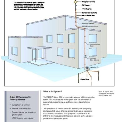
Erico System 3000 Dynasphere h5m6v
December 2019 46
Erico Gel 1x142f
August 2022 0Erico-gel v3z51
April 2021 0
Erico Rocha Miolo 1 1g6s5y
April 2023 0
Caminhos Cruzados - Erico Verissimo 2k3s4h
October 2019 425More Documents from "Juan E Torres M" 6p53h
Erico System 3000 y3h29
December 2019 50
Lista De Precios Terminales 3m 2010 701l4r
December 2019 31
Norma 1179 Hospitales Cableado.pdf 2h1970
January 2021 0
Lista De Precios Centelsa 286-2012 3o4e38
December 2022 0
Kyoritsu 161p16
January 2023 0