Effect Of Shear Lug On Anchor Bolt Tension In A Column Base Plate 2q5n6e
This document was ed by and they confirmed that they have the permission to share it. If you are author or own the copyright of this book, please report to us by using this report form. Report 2z6p3t
Overview 5o1f4z
& View Effect Of Shear Lug On Anchor Bolt Tension In A Column Base Plate as PDF for free.
More details 6z3438
- Words: 2,767
- Pages: 6
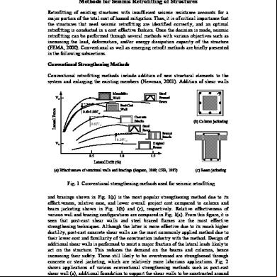
Challenges, Opportunities and Solutions in Structural Engineering and Construction – Ghafoori (ed.) © 2010 Taylor & Francis Group, London, ISBN 978-0-415-56809-8
Effect of shear lug on anchor bolt tension in a column base plate P.K. Khan Worley Parsons, Reading, Pennsylvania, USA
ABSTRACT: Major structural column bases in industrial applications are often subjected to significant amounts of base shear and overturning moment in addition to axial compression. The base plates for these columns are sometimes designed with a combination of shear lugs and anchor bolts to resist column reactions. Currently there is no guidance or established procedure to analyze shear lug for the overturning moment on the column base plate. This paper attempts to demonstrate how a shear lug welded at the bottom of the base plate and embedded inside a non-shrink grout pocket can affect the bending behavior of the base plate and reduce the anchor bolt tension as a result. Finite element models of the base plate/shear lug/anchor bolt system with non-linear springs are utilized to simulate the plate bending behavior. Resulting anchor bolt tensions are then compared between two base plate models, one with the shear lug and the other without the shear lug. 1
INTRODUCTION
The primary function of a column base plate is to transfer the column forces and moments to the foundation concrete with the help of adequate anchorage. The base plate anchorage can be developed in a number of different ways depending on the directions and magnitudes of column forces and moments that have to be transferred to the foundation. It can be developed either by anchor bolts, shear lugs or combination of both. A typical column base plate along with anchor bolts and shear lug is illustrated in Figure 1. Over the years various methods have been developed on the analysis and design of base plate with anchor bolts and shear lug in accordance with the requirements of either load and resistance factor design or allowable stress design. There are established design methodologies for design of base plate and anchor bolts based on elastic behavior of the base
plate, anchor bolts and the concrete underneath. There are also acceptable procedures for analysis of base plate with shear lugs and anchor bolts when the design shear and moment are assumed to act independently on shear lugs and anchor bolts respectively. However, very little information is currently available on analysis of base plates with shear lug and anchor bolts together considering significant interaction between the two. It is quite apparent that combined bending of the base plate and shear lug caused by design moment in column will alter the lever arm used for anchor bolt tension calculation. This in turn will affect the net tension carried by the anchor bolts. With the current requirements for ductile detailing of anchor bolts, specifically for columns that are part of seismic load resisting system in seismic design category D or above, any reduction in anchor bolt tension will benefit the design engineer and reduce construction cost. This paper attempts to address the behavior of base plate with shear lug and its effect on anchor bolt tension and base plate stress. Although only one column size with varying shear lugs has been utilized for this study, the results will indicate a trend of the influence that the shear lug is expected to have on anchor bolt tension. Figure 1 depicts a typical column base plate with anchor bolts and shear lug in a pre-formed grout pocket.
2
Figure 1.
FINITE ELEMENT MODEL
Bending behavior of a column base plate with welded shear lug can be quite complex depending on the magnitude of forces and moments to which it is subjected. It is also a function of the sizes and stiffness of the
Typical column base plate.
135
column and the shear lug. In addition, the base plate thickness plays an important role in distributing the column forces and moments to the foundation concrete via shear lug and anchor bolts. Finite element models are utilized to capture this complex bending behavior of the base plate. Rectangular plate elements are used to model the base plate, column and the shear lug whereas prismatic beam elements are used to simulate the anchor bolt behavior. The nodes of the plate elements for the base plate are attached to non-linear springs to capture accurate bending behavior of the baseplate in with foundation concrete. The anchor bolts are attached to concrete via non-linear springs representing the tensile stiffness of the anchor bolts. Figure 2 depicts an isometric view of the finite element model with the shear lug. Anchor bolts are not shown for clarity. A separate model is used for base plate without the shear lug. For this study a W14× 68 column is arbitrarily selected. A line of shear loads is applied on top of a 150 mm high column thus subjecting the base plate connection to shear force and overturning moment at the same time to replicate an actual column loading on the base plate. No axial compressive load is applied on the column for simplicity. The shear lug is selected from various W sections and placed concentric with the column. The height of shear lug is set at 150 mm. The size of the shear lug is varied to test the sensitivity of anchor bolt tension and plate stress with respect to the column-to-shear lug depth ratio. The shear lug sizes are selected such that the ratio of column flange width to shear lug flange width is approximately the same. The flange thickness for all the selected shear lugs is kept approximately the same to ensure that the stiffness of lug flanges is identical in all the analyses. The anchor bolts are attached to concrete foundation by tension only springs. The tensile stiffness of a cast-in-place anchor bolt is dependent not only on the deformation of the bolt itself but also on the deformation of the concrete cone that is required to develop the capacity of the anchor bolt and the stiffness of the bolt head. In order to simplify the calculation of this combined stiffness, the effective length of the anchor bolt is taken as 24 times the diameter of the anchor bolt as suggested by Wald, Zokol and Jaspart. Based
Figure 2.
Finite element model.
on this assumption the tensile stiffness (Kab ) of anchor bolt is calculated as follows: Kab = (Aab Es )/Lab
(1)
where Aab = tensile area of the anchor bolt; Es = Young’s Modulus of bolt material; Lab = effective length of the anchor bolt = 24dab , dab = diameter of the anchor bolt. For this study, 4–19 mm diameter ASTM F1554 Grade 36 anchor bolts are selected. Using Equation (1) above, anchor bolt tensile stiffness is calculated to be equal to 87.5 kN/mm per anchor bolt. The s for the base plate are modeled with compression only springs with a minimal lateral stiffness to for frictional resistance between the baseplate and concrete surfaces. Currently, there is no clearly defined method to calculate the compressive stiffness of foundation concrete that is in with the base plate. The compressive stiffness of foundation concrete is a function of a number of different variables such as concrete strength, foundation shape and thickness, amount of reinforcements in concrete, and stiffness of the underlying soil to name a few. A study by Steenhuis, Wald and Stark, demonstrated that the combined stiffness of base plate and 550 × 550 × 550 mm concrete block can be as much as 5500 kN/mm. But this block does not represent a typical foundation configuration nor was it tested on a typical soil ed boundary condition and hence the stiffness was possibly over estimated. For the current study, it is assumed that the foundation concrete, as a minimum, will possess as much stiffness in compression as the tensile stiffness of the anchor bolt. More likely the concrete stiffness will be much higher than that of the anchor bolts. Therefore, the concrete compressive stiffness is varied from 1 to 10 times the anchor bolt tensile stiffness with the assumption that the actual concrete stiffness will fall somewhere in this range. The average result from analyses of these different models is then utilized for the study of the resultant anchor bolt tension and base plate stress. Moreover when the concrete stiffness reaches around 875 kN/mm, as the finite element analysis suggests, the anchor bolt forces are not as sensitive to concrete stiffness. Shear lugs are generally embedded in a preformed concrete pocket which is ultimately filled with nonshrink high strength grout after the anchor bolts are set and the base plate is leveled. Therefore, it is appropriate to assume that the horizontal stiffness of the concrete surface adjacent to the shear lug flanges is of same magnitude as that of the concrete under the base plate i. e. 1 to 10 times the anchor bolt tensile stiffness. Figures 3 and 4 below illustrate the bending of the base plate without the shear lug and with the shear lug respectively. Note that the deflected shapes shown below are amplified more than 200 times the actual
136
Table 1.
Figure 3.
Base plate without shear lug.
Figure 4.
Base plate with shear lug.
shapes for illustration purpose. For these illustrations, 25.0 mm thick base plate models with 87.5 kN/mm anchor bolt stiffness and 875 kN/mm concrete stiffness are selected. Close examination of Figures 3 and 4 reveals that the column and the base plate rotations in the Figure 3 model are considerably larger than those in the Figure 4 model. This is due to the absence of the shear lug in the Figure 3 model. The analysis indicates that the column rotation in the Figure 3 model is at least 1.5 times more than that in the Figure 4 model. Thus the base plate with shear lug is more representative of a fixed base boundary condition than the base plate with anchor bolts alone.
Column size
Shear lug size
Column/lug ratio
Base plate thickness (mm)
W 14 × 68
W 4 × 13 W 6 × 12 W 8 × 13 W 10 × 15 W 12 × 16
3.50 2.33 1.75 1.40 1.17
13.00 19.00 25.00 32.00 38.00 45.00 50.00
The results of the analyses of different finite element models are plotted in Figure 5 to demonstrate the variation of anchor bolt tension. Figure 5 is a plot of change in anchor bolt tension with base plate thickness for different sizes of shear lugs. Tension Ratio indicated on the vertical axis of the plot is the ratio of anchor bolt tension from the control model (Figure 3) to that from the shear lug model (Figure 4). Thus the Tension Ratio indicated in Figure 5 is a measure of the reduction in anchor bolt tension in a shear lug model—the larger the ratio, the greater the reduction in anchor bolt tension. For the current study, maximum base plate stress always occurred adjacent to the tension face of the column flange. Base plate stress variation is not plotted since it is directly proportional to the anchor bolt tension and therefore follows a similar trend. Figure 5 reveals a few pieces of important information that would be of interest. There is considerably larger reduction in anchor bolt tension on thinner base plate than that on thicker base plate for all sizes of shear lugs. Also, a larger shear lug on a thinner base plate causes a greater reduction in anchor bolt tension than that caused by a smaller shear lug. It is also noticed that the tension ratio is not as sensitive to lug size for thicker base plate. This could be attributed to the combined bending rigidity of the base plate and shear lug system. For the same size of shear lug, the combined rigidity is approximately proportional to the cube of the base plate thickness. However, the results could perhaps be different for heavier sizes of column and shear lug.
4 3
List of finite element models.
DISCUSSION OF RESULTS
RESULTS
Table 1 below indicates different finite element models that were analyzed and examined for this study. Note that the control model (Figure 3) is the one with base plate and anchor bolts only. The anchor bolt tension for the shear lug model (Figure 4) is compared with the anchor bolt tension for the control model (Figure 3).
137
From the results indicated in Figure 5, it can be hypothesized that the presence of shear lug welded to the bottom of the base plate has a direct effect on the resultant anchor bolt tension. This is caused by the fact that the shear lug enhances the rigidity of the base plate thus affecting the overall bending of the anchorage system. There could be numerous different ways in which the
3.50 3.00
Tension Ratio
2.50 2.00 1.50 1.00 0.50 0.00 13.00
19.00
25.00
32.00
38.00
45.00
50.00
Base Plate Thickness (mm) Figure 5.
Figure 6.
Anchor bolt tension comparison.
Base plate free body diagram.
force equilibrium can be developed in the anchorage system. A possible distribution of shear lug and anchor bolt reactions is postulated as shown in Figure 6. From the free body diagram in Figure 6, summation of moments about column centerline above the base plate yields the following equation: Mu = Tab f + Vua a − Vub b + P(0.5d)
(2)
When, b < a and Vua < Vub
(3)
Summation of horizontal and vertical forces yields the following equations:
Vu = Vub − Vua
(4)
P − Tab = 0
(5)
where Mu = applied column moment; Vu = applied column shear; Tab = anchor bolt tension; Vua = lug reaction on tension side; Vub = lug reaction on compression side; a = distance of Vua from top of plate; b = distance of Vub from top of plate; d = depth of column; f = distance between centerlines of anchor bolt and column; and P = compressive reaction under base plate. Although there are various methodologies to determine the exact location of P, it is assumed that it acts approximately under the edge of the compressive flange of the column for simplicity. It is quite apparent from Equation (2) that the horizontal reactions (Vua and Vub ) on the shear lug effectively reduce the resultant anchor bolt tension (Tab ). The quantities a, b, Vua and Vub are not only functions of the base plate thickness but also dependent on the length and size of the shear lug, and the column-to-shear lug stiffness ratio. Subsequent approximations need to be made on the relationships between a, b and Vua , Vub in order to develop additional equations to solve for Tab, Vua and Vub .
138
5
CONCLUSIONS
Based on the results obtained from the finite element analyses shown earlier, the following conclusions can be drawn: There is significant dependence of anchor bolt tension on the presence of shear lug under a base plate. When a column base plate is subjected to a combination of shear force and overturning moment but no axial tension, there is definite reduction in anchor bolt tension when a shear lug is used in combination with anchor bolts in a baseplate as opposed to if the base plate is connected to foundation with anchor bolts alone. For a set of column and shear lug size, the tension reduction in anchor bolts decreases as the base plate thickness increases. The rate of tension reduction is more pronounced in thinner base plates. For a constant baseplate thickness, the tension reduction in anchor bolts increases as the shear lug size increases or the ratio of the column-to-shear lug size decreases. The tension reduction in anchor bolts in thicker base plates is not as sensitive to the ratio of the column to shear lug size as it is to thinner base plates.
139
However physical tests need to be performed to confirm the findings of this study and appropriate methodology can subsequently be developed for calculation of anchor bolt tension and base plate bending stress. REFERENCES ACI 318-05, Building Code Requirements for Structural Concrete, Appendix D—Anchoring to Concrete. Drake, Richard M. & Elkin, Sharon J., Beam-Column Base Plate Design—LRFD Method, Engineering Journal/First Quarter/1999. Fisher, James M. & Kloiber, Lawrence A., Base Plate and Anchor Rod Design, Second Edition, Steel Design Guide1, AISC. Steenhuis, C.M., Wald, F., Sokol, Z. & Stark, J.W.B., Resistance and Stiffness of Concrete in Compression and base Plate Bending. Wald, F., Sokol, Z. & Jaspart, J.P., Base Plate in Bending and Anchor Bolts in Tension, HERON Vol. 53 No. 1/2, (2008).
Related Documents c2h70

Effect Of Shear Lug On Anchor Bolt Tension In A Column Base Plate 2q5n6e
December 2019 50
January 2023 0

November 2019 41

Anchor Bolt Design For Shear And Tension 2if52
December 2019 67
Column Base Plate Design 4i6p1a
December 2019 122
Jabacus - Steel Column Base Plate 2571y
November 2022 0More Documents from "Saikat Kabiraj" 6e722s
Methods For Seismic Retrofitting Of Structures 6d1f59
November 2019 78
Etabs Examples Manual 45253x
October 2019 116
Effect Of Shear Lug On Anchor Bolt Tension In A Column Base Plate 2q5n6e
December 2019 50
Maths Syllabus Class 6.pdf 2r2q4s
November 2022 0
Four Quadrant Chopper Operation 15374z
December 2019 48