Design Of Glass Column 1y4fd
This document was ed by and they confirmed that they have the permission to share it. If you are author or own the copyright of this book, please report to us by using this report form. Report 2z6p3t
Overview 5o1f4z
& View Design Of Glass Column as PDF for free.
More details 6z3438
- Words: 641
- Pages: 8
ADVANCED DESIGN OF GLASS STRUCTURES Design of glass column Viorel Ungureanu European Erasmus Mundus Master Course
Sustainable Constructions under Natural Hazards and Catastrophic Events 520121-1-2011-1-CZ-ERA MUNDUS-EMMC
Objectives of the lecture Objectives Composite section Non-composite section Accidental situation
Worked example
•
1) Assess the resistance of a glass column made of bundled tubes, ing a roof, as shown in the figure. Tubes are attached together by the use of adhesive which enables them to work as: a) a single composite section; b) a non-composite section. L= c1 4000 mm tube outside diameter d = 135 mm thickness t = 6 mm Design value of glass strength: in compression fcd = c2 400 MPa in tension ftd = 50 MPa
Design of glass column
a) Section A - A
L b) Section A - A after failure
116,91 184,41
67,5
2) Assess the resistance of the same column with two broken tubes - see the figure. 2
Composite section Objectives
Accidental situation
• tube outside diameter
d = 135 mm
• thickness
t = 6 mm
• area of one tube
A0
2
d 2 d 2t A0 4
y
• moment of inertia of one tube
z
67,5
Non-composite section
Tubes are attached by use of adhesive which enables them to work as a single composite section
116,91
Composite section
d 4 d 2t 4 I0 64
67,5
I0
• Moment of inertia of composite section Iy ,Iz
I y 3I 0 4 I 0 A0 r12
r = 116,91mm 1
I z I 0 4 I 0 A0 r22 2 I 0 A0 r32
r2 = 67,5mm r3 = 135,0mm
3
Composite section Objectives Composite section Non-composite section Accidental situation
• Maximal resistance in compression without buckling
N max cd 7 A0 • Critical force
N cr ,comp
2 EI 2 Lcr
• “safety factor” – restriction for capacity by Ncr/4
N Rd ,1
N cr ,comp 4
4
Non-composite section Objectives Composite section
Tubes without connection, each tube share axial load equally • Critical force of one tube
Non-composite section Accidental situation
N cr , 0
2 EI 0 2 Lcr
• Capacity of the column
N Rd , 2
7 N cr , 0 4
5
Accidental situation Objectives Composite section Non-composite section Accidental situation
2) Accidental situation – two broken tubes • New location of gravity axis
yT
3 A0 184,41 2 A0 67,5 5 A0
yT
116,91 184,41
67,5
• Moment of inertia IyT of 5 tube – composite section 2
2
I yT 3I 0 3 A0 184,41 yT 2 I 0 2 A0 yT 67,5 • Distance to the tensioned fibres dt • Distance to the compressed fibres dc • Critical force
N cr , yT
2 EI yT L2cr
yT 116,91 184,41
67,5
tensioned fibres
• Eccentricity of force
e 184,41 yT
6
Accidental situation Objectives Composite section Non-composite section Accidental situation
a) axial force + moment – tensioned fibres
I yT
W y ,tension
• Cross-section modulus
dt
• maximal allowed force for tensioned fibres
f td
N Ed N e Ed 5 A0 W y ,tension
N Ed
b) axial force + moment – compressed fibres • Cross-section modulus
W y ,compression
I yT dc
• maximal allowed force for compressed fibres
N Ed N Ed e f cd 5 A0 W y ,compression Conclusion:
N Ed
Preliminary resistance of glass column
7
Thank you for your attention [email protected] http://steel.fsv.cvut.cz/suscos
8
Related Documents c2h70

Design Of Glass Column 1y4fd
December 2019 69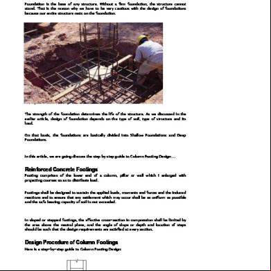
Design Of Column Bases 3n3z2v
December 2019 53
Design Of Column Footing q2s10
December 2021 0
Design Of Stone Column 2n3oy
December 2019 45
Column Design 4m132j
April 2020 37
Design Of Stripping Column .pdf 2z2x1s
November 2019 78More Documents from "Cristiana Gruia" 53z5v

Part 1 - Building Structure - General.pdf 2h4g3w
December 2019 56
Design Of Glass Column 1y4fd
December 2019 69
Zile Lucratoare 2018 41f5
February 2022 0
178 00 Adit Paper Iiif Transfer Pricing Manual Combined 4u5c23
November 2019 104
Oferta Telefoane Telekom.pdf 1d3f2i
December 2019 75