Dbr Structural Design Basis Report Avigna 2x296e
This document was ed by and they confirmed that they have the permission to share it. If you are author or own the copyright of this book, please report to us by using this report form. Report 2z6p3t
Overview 5o1f4z
& View Dbr Structural Design Basis Report Avigna as PDF for free.
More details 6z3438
- Words: 1,757
- Pages: 8
MAHIMTURA CONSULTANTS PVT. LTD
Project :- Residential Tower at Curry Road, Mumbai For NISH DEVELOPERS PVT LTD
C/ 6589 /2014
Date: 10/04/14 DESIGN BASIS REPORT
PROJECT
:
PROPOSED RESIDENTIAL TOWER AT CURRY ROAD MUMBAI
CLEINT
:
M/S. NISH DEVELOPERS PVT. LTD.
ARCHITECT
:
VIVEK BHOLE
STRUCTURAL CONSULTANT
:
M/S. MAHIMTURA CONSULTANTS PVT. LTD.
GEO-TECH CONSULTANTS
:
PROF. G. B . CHAUDHARI
1.
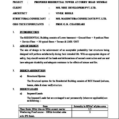
INTRODUCTION The RESIDENTIAL Building consists of Lower basement + Ground floor + 9 podium Floor + Service Floor + 56 typical floors + Terrace & LMR / OHT
2.
AIM OF DESIGN The aim of design is the achievement of an acceptable probability that structures being designed will perform satisfactorily during their intended life. With an appropriate degree of safety, they should sustain all the loads and deformations of normal construction and use and have adequate durability and adequate resistance to the effects of misuse and fire.
3.
DESIGN ASSUMPTION a)
Structural System The Structural system for the Residential Building consists of RCC framed (column, beams, slabs & shear wall) structure.
3.
DESIGN LOADS a)
Imposed Loads The Imposed Loads that are envisaged to act permanently (wherever applicable) are as following :-
Item Floor finish 20thk tiles on 20thk cement mortar Weathering Proof course – 100thk brickbat coba
Intensity in KN/m2 of plan area 1.5 2
with IPS finish.
Page No. 1
MAHIMTURA CONSULTANTS PVT. LTD
Project :- Residential Tower at Curry Road, Mumbai For NISH DEVELOPERS PVT LTD
The superimposed load or otherwise live load is assessed based on the occupancy classifications as per IS:875 (Part –2) – 1987 and are listed as below. Residential building Residential building Residential building Residential building Residential building Multipurpose Hall Podium (Parking floors) Refuse floor 4.
Occupancy Classification Residential Room Toilets & Bath Rooms Staircase & Corridors Roof with access Car parking (Double stack parking) -
UDL (KN/m2) 2 2 3 1.5 4 5 4
WIND LOADS ; Wind tunnel report is enclosed ;
5.
Base dimension along X-dir, L
=
112.65 m
Base dimension along Y-dir, B
=
54.7 m
Time period x direction as per 0.1 n
=
6.8 sec
Time period y direction as per 0.1 n
=
6.8 sec
Time period x direction as per E tabs model
=
6.45 sec
Time period y direction as per E tabs model
=
5.99 sec
Aspect Ratio = H/L = 255.35/ 112.65
=
2.27 …. Along X- dir
Aspect Ratio = H/B = 255.35/ 54.7
=
4.67 …. Along Y- dir
EARTHQUAKE LOAD The loading due to earthquake is assessed based on the provisions of IS:1893(Part-1):2002
Seismic Zone
=
III
Table-2
Zone factor (Z)
=
0.16.
Table-6
Importance Factor (I)
=
1.00 (Residential Building)
Table-7
Response Reduction Factor (R)
=
4.0
Height of building (H)
=
255.35 m
Base dimension of the building along the considered direction of lateral force (D )
=
Soil type
=
L = 112.65 m B = 54.7 m Hard soil
Page No. 2
MAHIMTURA CONSULTANTS PVT. LTD
Project :- Residential Tower at Curry Road, Mumbai For NISH DEVELOPERS PVT LTD
Fundamental natural time period (Ts) with INFILL WALLS in x direction Ts
Sa/g
=
0.09 x h / d 0.5
=
0.09 x 255.35 / 112.65 0.5
=
2.15
=
0.46
……..from CL.7.6.2 – IS1893 (part – I):2002
from FIG-2 IS 1893 (part I):2002
Fundamental natural time period (Ts) with INFILL WALLS in y direction Ts
Sa/g
=
0.09 x h / d 0.5
=
0.09 x 255.35 / 54.7 0.5
=
3.02
=
0.33
……..from CL.7.6.2 – IS1893 (part – I):2002
from FIG-2 IS 1893 (part I):2002
HORIZONTAL SEISMIC CO-EFFICIENT IN X DIRECTION Ah
=
Z x I x Sa 2 xRxg 0.16 x 1 x 0.46 2x4
= 0.0093
DESIGN BASE SHEAR IN X DIRECTION Vb
=
Ah x W
=
0.0093 X 3978616.56
=
37010.39 K N
HORIZONTAL SEISMIC CO-EFFICIENT IN Y DIRECTION Ah
=
Z x I x Sa 2 xRxg 0.16 x 1 x 0.33 2x4
= 0.0066
DESIGN BASE SHEAR IN Y DIRECTION Vb
=
Ah x W
=
0.0066 X 3978616.56
=
26258.87 K N
Page No. 3
MAHIMTURA CONSULTANTS PVT. LTD
Project :- Residential Tower at Curry Road, Mumbai For NISH DEVELOPERS PVT LTD
STOREY DRIFT The storey drift in any storey due to the minimum specified design lateral force, with partial load factor of 1.0, shall not exceed 0.004 times the storey height. SOFTWARE USED:ETABS SAFE 6.
CHECK FOR LATERAL SWAY AS PER IS 456-2000 The allowable lateral sway under wind loading at top limited to H/500, where H is total height of building.
7.
BASIC LOADS AND LOAD COMBINATIONS The various loads are combined in accordance with the stipulations in IS:875 (Part 5)-1987. Wherever imposed load is combined with earthquake load the appropriate part of the imposed load as specified in IS:1893-2002 is adopted both for evaluating earthquake effect and for combined load effects, used in such combination. DL+LL DL+EQX DL-EQX DL+EQZ DL-EQZ DL+WLX DL-WLX DL+WLZ DL-WLZ *****FACTORED LOAD CASES 1.5[DL+LL] 1.5[DL+EQX] 1.5[DL-EQX] 1.5[DL+EQZ] 1.5[DL-EQZ] 1.2[DL+LL+EQX] 1.2[DL+LL-EQX] 1.2[DL+LL+EQZ] 1.2[DL+LL-EQZ]
Page No. 4
MAHIMTURA CONSULTANTS PVT. LTD
Project :- Residential Tower at Curry Road, Mumbai For NISH DEVELOPERS PVT LTD
****STRESS REVERSAL [0.9DL+1.5EQX] [0.9DL-1.5EQX] [0.9DL+1.5EQZ] [0.9DL-1.5EQZ] **********WIND 1.5[DL+WLX] 1.5[DL-WLX] 1.5[DL+WLZ] 1.5[DL-WLZ] 1.2[DL+LL+WLX] 1.2[DL+LL-WLX] 1.2[DL+LL+WLZ] 1.2[DL+LL-WLZ] ***********STRESS REVERSAL [0.9DL+1.5WLX] [0.9DL-1.5WLX] [0.9DL+1.5WLZ] [0.9DL-1.5WLZ] 8.
LOAD FACTORS FOR DESIGN Description of Load Combination
Load Factor for Primary Load Cases Live Wind Seismic Lo Load Load Load ad 1.5 1.5 0.0 0.0 1.5 0 1.5 0.0 1.5 0 0 1.5 1.2 1.2 1.2 0.0 1.2 1.2 0 1.2 0.9 0 1.5 0.0 0.9 0 0 1.5
Dead Dead load + Live load Dead load + Wind load Dead load + Seismic load Dead load + Live load + Wind load Dead load + Live load + Seismic load Dead load + Wind load Dead load + Seismic load 9.
ANALYSIS METHOD The structure is analysed for Gravity Load and Lateral loads due to Earthquake/Wind loads and its combinations.
10.
DESIGN METHODOLOGY
Page No. 5
MAHIMTURA CONSULTANTS PVT. LTD
Project :- Residential Tower at Curry Road, Mumbai For NISH DEVELOPERS PVT LTD
All structural RCC have been designed according to the Limit State Method as specified in IS: 456-2000. All structural steel have been designed according to specified in IS: 800-2007. Appropriate loads and its combinations, as per relevant clauses in Code IS: 456-2000, Code IS: 875 (Part-5) 1987, for the most unfavorable effects are chosen for design. 11.
MATERIALS The self-weight of the various elements are computed based on the built weight of materials as given below:-
12
Materials
Unit Weight in KN/m3
Steel Plain Concrete Reinforced Concrete Soil Water Brick, Fly ash block
78.50 24.00 25.00 18.00 10.00 20.00
CONSTRUCTION DETAILS 1.
Raft Foundation
-
Concrete Mix
M:40
Steel Fe500
2.
Columns
-
Concrete Mix Steel
M: 60 ,M;50 , M40 , M30 Fe500
3.
Beams & Slabs
-
M50 , M40 , M30 & Steel Fe 500
4.
External Wall
-
150 thk LIGHT WT Block wall as per architect layout.
5. 6.
Internal Wall Floor to Floor HT
-
125 thk LIGHT WT block wall as per architect layout. 3.85 m
13.
CONCRETE
14.
All the concrete items for the construction have the following characteristics Grade of Concrete = M60/M50/M40/M30 (Concrete design Mix as per IS 456-2000) M15 (For P.C.C. ) Aggregate = 20mm and down size, mechanically crushed Aggregate REINFORCEMENT Steel reinforcement shall be of Grade Fe500 conforming to IS:1786-1985.
15
STRUCTURAL STEEL Structural steel used in project is of Grade Fe250 and Fe350.
16.
EXPOSURE CONDITION
Page No. 6
MAHIMTURA CONSULTANTS PVT. LTD
Project :- Residential Tower at Curry Road, Mumbai For NISH DEVELOPERS PVT LTD
Structural elements below Plinth level and Exterior External faces of walls are designed for Moderate exposure condition and internal faces of walls, floor beams and slabs are designed for mild exposure condition as per Table 16 of IS 456-2000. 17
COVER TO REINFORCEMENT The clear cover to main reinforcement shall be as per IS: 456-2000.
18.
FOUNDATION SYSTEM The structure is ed on columns and shear wall with RAFT foundation. S.B.C. considered as per soil investigation report provided by PROF. G. B. CHAUDHARI
19.
CODES & STANDARDS All the designs are conforming to the relevant Indian Standards. Some of the relevant Indian Standard Codes, which have been followed for the structural designs, are given below. Code
Description
IS:875 (Part-1)-1987
Code of Practice for Design Loads (Other than Earthquake) for Building and Structures-Unit Weights of Buildings Materials and Stored Material.
IS:875 (Part-2)-1987
Code of Practice for Design Loads (Other than Earthquake) for Building and Structures-Imposed loads
IS:875 (Part-3)-1987
Code of Practice for Design Loads (Other than Earthquake) for Buildings and Structures –Wind Load.
IS:875 (Part-5)-1987
Code of Practice for Design Loads (Other than Earthquake) for Buildings and Structures - Special Loads and Load Combinations Code of Practice for Plain and Reinforced Concrete
IS:456 -2000 IS:1893 (Part-1)-2002
Indian Standard Criteria for Earthquake Resistant Design of Structures
IS:432 (Part-1)-1982
Specification of Mild Steel and Medium Tensile Steel bars and Hard drawn Steel Wire for concrete reinforcement –Mild Steel and Medium Tensile Steel Bars. Specification of Mild Steel and Medium Tensile Steel bars and Hard drawn Steel Wire for concrete reinforcement –Hard drawn Steel Wire. Specification for High Strength Deformed Steel Bars and Wires for Concrete Reinforcement Ductile Detailing of reinforced concrete structures subjected to seismic forces – code of practice. Indian Standard Code of practice for Design & Construction foundations in Soil: General Requirements. Indian Standard Code of practice for Fire Safety Of Buildings (General) : Details Of Construction.
IS:432 (Part-2)-1982 IS:1786-1985 IS:13920-1993 IS:1904 IS:1642-1989
TYPICAL CALCULATION FOR ARRIVING AT DUCTILE DETAILING:
Page No. 7
MAHIMTURA CONSULTANTS PVT. LTD
Project :- Residential Tower at Curry Road, Mumbai For NISH DEVELOPERS PVT LTD
Size
=
1400 x 1200
As per IS:13920 : 1993 Clause 7.4.8 The area of cross section, Ash, of the bar forming rectangular hoop to be used as special confining reinforcement shall not be less than. Ash
=
0.18 x s x h x fck fy
Ag - 1.0 Ak
For Concrete Mix M:50 fck =
50 N/mm2
Ash =
0.18 x 75 x 300 x
Ash
=
405
1.10
=
40.50mm2
Clear cover = 40 mm 50 1400 x 1200- - 1.0 500 1336 x 1136
- 1.0
Provide 8 @ 75mm C/C as hoops / links
H. R. MAHIMTURA Consulting Structural Engineer Registration No. STR/M/63
M/s. Mahimtura Consultants Pvt Ltd Consulting Engineers, Unique House, 3rd Floor, 25, S. A. Brelvi Road, Fort, Mumbai – 400 001.
Page No. 8
Project :- Residential Tower at Curry Road, Mumbai For NISH DEVELOPERS PVT LTD
C/ 6589 /2014
Date: 10/04/14 DESIGN BASIS REPORT
PROJECT
:
PROPOSED RESIDENTIAL TOWER AT CURRY ROAD MUMBAI
CLEINT
:
M/S. NISH DEVELOPERS PVT. LTD.
ARCHITECT
:
VIVEK BHOLE
STRUCTURAL CONSULTANT
:
M/S. MAHIMTURA CONSULTANTS PVT. LTD.
GEO-TECH CONSULTANTS
:
PROF. G. B . CHAUDHARI
1.
INTRODUCTION The RESIDENTIAL Building consists of Lower basement + Ground floor + 9 podium Floor + Service Floor + 56 typical floors + Terrace & LMR / OHT
2.
AIM OF DESIGN The aim of design is the achievement of an acceptable probability that structures being designed will perform satisfactorily during their intended life. With an appropriate degree of safety, they should sustain all the loads and deformations of normal construction and use and have adequate durability and adequate resistance to the effects of misuse and fire.
3.
DESIGN ASSUMPTION a)
Structural System The Structural system for the Residential Building consists of RCC framed (column, beams, slabs & shear wall) structure.
3.
DESIGN LOADS a)
Imposed Loads The Imposed Loads that are envisaged to act permanently (wherever applicable) are as following :-
Item Floor finish 20thk tiles on 20thk cement mortar Weathering Proof course – 100thk brickbat coba
Intensity in KN/m2 of plan area 1.5 2
with IPS finish.
Page No. 1
MAHIMTURA CONSULTANTS PVT. LTD
Project :- Residential Tower at Curry Road, Mumbai For NISH DEVELOPERS PVT LTD
The superimposed load or otherwise live load is assessed based on the occupancy classifications as per IS:875 (Part –2) – 1987 and are listed as below. Residential building Residential building Residential building Residential building Residential building Multipurpose Hall Podium (Parking floors) Refuse floor 4.
Occupancy Classification Residential Room Toilets & Bath Rooms Staircase & Corridors Roof with access Car parking (Double stack parking) -
UDL (KN/m2) 2 2 3 1.5 4 5 4
WIND LOADS ; Wind tunnel report is enclosed ;
5.
Base dimension along X-dir, L
=
112.65 m
Base dimension along Y-dir, B
=
54.7 m
Time period x direction as per 0.1 n
=
6.8 sec
Time period y direction as per 0.1 n
=
6.8 sec
Time period x direction as per E tabs model
=
6.45 sec
Time period y direction as per E tabs model
=
5.99 sec
Aspect Ratio = H/L = 255.35/ 112.65
=
2.27 …. Along X- dir
Aspect Ratio = H/B = 255.35/ 54.7
=
4.67 …. Along Y- dir
EARTHQUAKE LOAD The loading due to earthquake is assessed based on the provisions of IS:1893(Part-1):2002
Seismic Zone
=
III
Table-2
Zone factor (Z)
=
0.16.
Table-6
Importance Factor (I)
=
1.00 (Residential Building)
Table-7
Response Reduction Factor (R)
=
4.0
Height of building (H)
=
255.35 m
Base dimension of the building along the considered direction of lateral force (D )
=
Soil type
=
L = 112.65 m B = 54.7 m Hard soil
Page No. 2
MAHIMTURA CONSULTANTS PVT. LTD
Project :- Residential Tower at Curry Road, Mumbai For NISH DEVELOPERS PVT LTD
Fundamental natural time period (Ts) with INFILL WALLS in x direction Ts
Sa/g
=
0.09 x h / d 0.5
=
0.09 x 255.35 / 112.65 0.5
=
2.15
=
0.46
……..from CL.7.6.2 – IS1893 (part – I):2002
from FIG-2 IS 1893 (part I):2002
Fundamental natural time period (Ts) with INFILL WALLS in y direction Ts
Sa/g
=
0.09 x h / d 0.5
=
0.09 x 255.35 / 54.7 0.5
=
3.02
=
0.33
……..from CL.7.6.2 – IS1893 (part – I):2002
from FIG-2 IS 1893 (part I):2002
HORIZONTAL SEISMIC CO-EFFICIENT IN X DIRECTION Ah
=
Z x I x Sa 2 xRxg 0.16 x 1 x 0.46 2x4
= 0.0093
DESIGN BASE SHEAR IN X DIRECTION Vb
=
Ah x W
=
0.0093 X 3978616.56
=
37010.39 K N
HORIZONTAL SEISMIC CO-EFFICIENT IN Y DIRECTION Ah
=
Z x I x Sa 2 xRxg 0.16 x 1 x 0.33 2x4
= 0.0066
DESIGN BASE SHEAR IN Y DIRECTION Vb
=
Ah x W
=
0.0066 X 3978616.56
=
26258.87 K N
Page No. 3
MAHIMTURA CONSULTANTS PVT. LTD
Project :- Residential Tower at Curry Road, Mumbai For NISH DEVELOPERS PVT LTD
STOREY DRIFT The storey drift in any storey due to the minimum specified design lateral force, with partial load factor of 1.0, shall not exceed 0.004 times the storey height. SOFTWARE USED:ETABS SAFE 6.
CHECK FOR LATERAL SWAY AS PER IS 456-2000 The allowable lateral sway under wind loading at top limited to H/500, where H is total height of building.
7.
BASIC LOADS AND LOAD COMBINATIONS The various loads are combined in accordance with the stipulations in IS:875 (Part 5)-1987. Wherever imposed load is combined with earthquake load the appropriate part of the imposed load as specified in IS:1893-2002 is adopted both for evaluating earthquake effect and for combined load effects, used in such combination. DL+LL DL+EQX DL-EQX DL+EQZ DL-EQZ DL+WLX DL-WLX DL+WLZ DL-WLZ *****FACTORED LOAD CASES 1.5[DL+LL] 1.5[DL+EQX] 1.5[DL-EQX] 1.5[DL+EQZ] 1.5[DL-EQZ] 1.2[DL+LL+EQX] 1.2[DL+LL-EQX] 1.2[DL+LL+EQZ] 1.2[DL+LL-EQZ]
Page No. 4
MAHIMTURA CONSULTANTS PVT. LTD
Project :- Residential Tower at Curry Road, Mumbai For NISH DEVELOPERS PVT LTD
****STRESS REVERSAL [0.9DL+1.5EQX] [0.9DL-1.5EQX] [0.9DL+1.5EQZ] [0.9DL-1.5EQZ] **********WIND 1.5[DL+WLX] 1.5[DL-WLX] 1.5[DL+WLZ] 1.5[DL-WLZ] 1.2[DL+LL+WLX] 1.2[DL+LL-WLX] 1.2[DL+LL+WLZ] 1.2[DL+LL-WLZ] ***********STRESS REVERSAL [0.9DL+1.5WLX] [0.9DL-1.5WLX] [0.9DL+1.5WLZ] [0.9DL-1.5WLZ] 8.
LOAD FACTORS FOR DESIGN Description of Load Combination
Load Factor for Primary Load Cases Live Wind Seismic Lo Load Load Load ad 1.5 1.5 0.0 0.0 1.5 0 1.5 0.0 1.5 0 0 1.5 1.2 1.2 1.2 0.0 1.2 1.2 0 1.2 0.9 0 1.5 0.0 0.9 0 0 1.5
Dead Dead load + Live load Dead load + Wind load Dead load + Seismic load Dead load + Live load + Wind load Dead load + Live load + Seismic load Dead load + Wind load Dead load + Seismic load 9.
ANALYSIS METHOD The structure is analysed for Gravity Load and Lateral loads due to Earthquake/Wind loads and its combinations.
10.
DESIGN METHODOLOGY
Page No. 5
MAHIMTURA CONSULTANTS PVT. LTD
Project :- Residential Tower at Curry Road, Mumbai For NISH DEVELOPERS PVT LTD
All structural RCC have been designed according to the Limit State Method as specified in IS: 456-2000. All structural steel have been designed according to specified in IS: 800-2007. Appropriate loads and its combinations, as per relevant clauses in Code IS: 456-2000, Code IS: 875 (Part-5) 1987, for the most unfavorable effects are chosen for design. 11.
MATERIALS The self-weight of the various elements are computed based on the built weight of materials as given below:-
12
Materials
Unit Weight in KN/m3
Steel Plain Concrete Reinforced Concrete Soil Water Brick, Fly ash block
78.50 24.00 25.00 18.00 10.00 20.00
CONSTRUCTION DETAILS 1.
Raft Foundation
-
Concrete Mix
M:40
Steel Fe500
2.
Columns
-
Concrete Mix Steel
M: 60 ,M;50 , M40 , M30 Fe500
3.
Beams & Slabs
-
M50 , M40 , M30 & Steel Fe 500
4.
External Wall
-
150 thk LIGHT WT Block wall as per architect layout.
5. 6.
Internal Wall Floor to Floor HT
-
125 thk LIGHT WT block wall as per architect layout. 3.85 m
13.
CONCRETE
14.
All the concrete items for the construction have the following characteristics Grade of Concrete = M60/M50/M40/M30 (Concrete design Mix as per IS 456-2000) M15 (For P.C.C. ) Aggregate = 20mm and down size, mechanically crushed Aggregate REINFORCEMENT Steel reinforcement shall be of Grade Fe500 conforming to IS:1786-1985.
15
STRUCTURAL STEEL Structural steel used in project is of Grade Fe250 and Fe350.
16.
EXPOSURE CONDITION
Page No. 6
MAHIMTURA CONSULTANTS PVT. LTD
Project :- Residential Tower at Curry Road, Mumbai For NISH DEVELOPERS PVT LTD
Structural elements below Plinth level and Exterior External faces of walls are designed for Moderate exposure condition and internal faces of walls, floor beams and slabs are designed for mild exposure condition as per Table 16 of IS 456-2000. 17
COVER TO REINFORCEMENT The clear cover to main reinforcement shall be as per IS: 456-2000.
18.
FOUNDATION SYSTEM The structure is ed on columns and shear wall with RAFT foundation. S.B.C. considered as per soil investigation report provided by PROF. G. B. CHAUDHARI
19.
CODES & STANDARDS All the designs are conforming to the relevant Indian Standards. Some of the relevant Indian Standard Codes, which have been followed for the structural designs, are given below. Code
Description
IS:875 (Part-1)-1987
Code of Practice for Design Loads (Other than Earthquake) for Building and Structures-Unit Weights of Buildings Materials and Stored Material.
IS:875 (Part-2)-1987
Code of Practice for Design Loads (Other than Earthquake) for Building and Structures-Imposed loads
IS:875 (Part-3)-1987
Code of Practice for Design Loads (Other than Earthquake) for Buildings and Structures –Wind Load.
IS:875 (Part-5)-1987
Code of Practice for Design Loads (Other than Earthquake) for Buildings and Structures - Special Loads and Load Combinations Code of Practice for Plain and Reinforced Concrete
IS:456 -2000 IS:1893 (Part-1)-2002
Indian Standard Criteria for Earthquake Resistant Design of Structures
IS:432 (Part-1)-1982
Specification of Mild Steel and Medium Tensile Steel bars and Hard drawn Steel Wire for concrete reinforcement –Mild Steel and Medium Tensile Steel Bars. Specification of Mild Steel and Medium Tensile Steel bars and Hard drawn Steel Wire for concrete reinforcement –Hard drawn Steel Wire. Specification for High Strength Deformed Steel Bars and Wires for Concrete Reinforcement Ductile Detailing of reinforced concrete structures subjected to seismic forces – code of practice. Indian Standard Code of practice for Design & Construction foundations in Soil: General Requirements. Indian Standard Code of practice for Fire Safety Of Buildings (General) : Details Of Construction.
IS:432 (Part-2)-1982 IS:1786-1985 IS:13920-1993 IS:1904 IS:1642-1989
TYPICAL CALCULATION FOR ARRIVING AT DUCTILE DETAILING:
Page No. 7
MAHIMTURA CONSULTANTS PVT. LTD
Project :- Residential Tower at Curry Road, Mumbai For NISH DEVELOPERS PVT LTD
Size
=
1400 x 1200
As per IS:13920 : 1993 Clause 7.4.8 The area of cross section, Ash, of the bar forming rectangular hoop to be used as special confining reinforcement shall not be less than. Ash
=
0.18 x s x h x fck fy
Ag - 1.0 Ak
For Concrete Mix M:50 fck =
50 N/mm2
Ash =
0.18 x 75 x 300 x
Ash
=
405
1.10
=
40.50mm2
Clear cover = 40 mm 50 1400 x 1200- - 1.0 500 1336 x 1136
- 1.0
Provide 8 @ 75mm C/C as hoops / links
H. R. MAHIMTURA Consulting Structural Engineer Registration No. STR/M/63
M/s. Mahimtura Consultants Pvt Ltd Consulting Engineers, Unique House, 3rd Floor, 25, S. A. Brelvi Road, Fort, Mumbai – 400 001.
Page No. 8
Related Documents c2h70
Dbr Structural Design Basis Report Avigna 2x296e
April 2020 25
1. Structural Design Basis Report-r4 392w2f
October 2019 42
Structural Dbr Sample Report.pdf 5p1e3
October 2019 338
Civil- Structural Dbr 6n6u24
December 2019 58
Eurocode Basis Of Structural Design Pdf 46i3f
February 2022 0
Sample Dbr Report 641v30
November 2019 67More Documents from "swapnil" 2s6p2v

Formula Writer 33261a
March 2023 0
Engineering Mechanics 3w5s2k
December 2019 183
Dbr Structural Design Basis Report Avigna 2x296e
April 2020 25
Upsc Ese 2017 Prelims Answer Key By Made Easy - Ce 6655g
December 2019 375
Electromagnetic Brake Project 4a732z
December 2021 0