Column Design To Bs8110 Template 3366e
This document was ed by and they confirmed that they have the permission to share it. If you are author or own the copyright of this book, please report to us by using this report form. Report 2z6p3t
Overview 5o1f4z
& View Column Design To Bs8110 Template as PDF for free.
More details 6z3438
- Words: 1,120
- Pages: 6
CLIENT PROJECT Location Sub-Location REF
UNITED ENGINEERING SERVICES LTD. PIARCO GENERATOR BUILDING
Date By
9-Jun-15 M Rampersad
Structural Frame RC Column Design
DESCRIPTION
RC COLUMN DESIGN
OUTPUT
CLIENT PROJECT Location Sub-Location
Date By
UNITED ENGINEERING SERVICES LTD. PIARCO GENERATOR BUILDING
9-Jun-15 M Rampersad
Structural Frame RC Column Design
REF
DESCRIPTION
OUTPUT
References Used 1
Reinforced Concrete Design, 4th ed, Moseley & Bungey
2
BS8110: 1997, Structural Use of Concrete
3
STAAD Model analysis
4
ASTM A615: 04, Std. Spec for Deformed & Plain Carbon Steel Bars etc.
MEMBER GEOMETRY Geometric data
450
450.0
mm
450
Member depth, h =
450.0
mm
450
mm 2 N/mm
Cover to reinforcement =
40.0
Conc. compressive strength, fcu =
30.0
Tension rfct strength, fy =
420.0
Shear rfct strength, fyv =
280.0
N/mm N/mm2
Length between restraints, LO =
3500.0
mm
20.0
mm
450 40 00
4 4
Member width, b =
Nominal aggregate size
2
OK against cover
Min. allowable bar spacing =
25.0 mm
Effective depth, h' =
400.0 mm
400
Effective width, b' =
410.0 mm 2,160,000,000 Nm
410
bd2fcu term = Gross cross-sectional area, Ag =
202,500 mm
410
2
Check effective height & slenderness X-X axis condition at TOP
1.0
condition at BOTTOM
2.0
end restraint beta,
2 - Tbl 3.19 2 - Cl. 3.8.1.6.1
0.80 2,800 mm
Effective height (major axis), lex = LO =
2 - Cl. 3.8.1.3.
Classification (short or slender) =
6.2 Short
Y-Y axis condition at TOP
3.0
condition at BOTTOM
2.0
end restraint beta,
2 - Tbl 3.19 2 - Cl. 3.8.1.6.1
Effective height (minor axis), ley = LO =
2 -Cl. 3.8.1.3.
Classification (short or slender) =
0.95 3,325 mm 7.4 Short
Slenderness limit 2 - Cl. 3.8.1.7
Slenderness limit (LO should be <60* min dimension) =
27,000 mm
Slenderness limit OK
CLIENT PROJECT Location Sub-Location
Date By
UNITED ENGINEERING SERVICES LTD. PIARCO GENERATOR BUILDING
9-Jun-15 M Rampersad
Structural Frame RC Column Design
REF
DESCRIPTION
OUTPUT
ULS LOAD DATA Axial load, N =
150.0 50.0
kN kNm
150kN
Moment about major axis, MX = Moment about minor axis, MY =
20.0
kNm
20kNm
Max shear force, V =
75.0
kN
STAAD Member Ref =
115
Load Case =
114
3
1 - Sxn 9.4.4
150kN 50kNm
1 - Tbl 9.4
20kNm
Check MX/h' =
125.0 kN
Check MY/b' =
48.8 kN
N/bdfcu =
0.02 [unitless]
coefficient beta, =
1.00 [unitless]
beta*(h'/b') =
0.98 [unitless]
50kNm
Since Mx/h'>My/b', Use single axis design moment about X-axis Use M'x as the design moment, M =
69.5 kNm
Total steel required, As req = (see supplemental calcs)
2 1,040 mm
REINFORCEMENT CHECKS 2 - Cl. 3.4.4.4
Calculation for reinforcement
Select bar diameter = Specify number of bars = Compression C i steel t l provided, id d As prov = Number of layers = Min. spacing between bars =
20 mm 4 Nr 2 1,260 mm 2 330.0 mm
Spacing OK
Provide 4Nr T20 bars in 2 layer(s) Check for minimum steel 2 - Tbl. 3.25
100 AS/AC =
0.62 %
2 - Cl. 3.12.5.3
Recommended value (Minimum) =
0.40 %
Min. steel OK
2 - Cl. 3.12.6.2
Recommended value (Maximum) =
4.00 %
Max. steel OK
SHEAR REINFORCEMENT CHECKS 2 - Cl. 3.4.5.2
Design (Actual) shear stress, = V/bvd V=
75.0 kN
bv = b =
450 0 mm 450.0
d=
400.0 mm
∴ Design (actual) shear stress, =
2 0.42 N/mm
CLIENT PROJECT Location Sub-Location
PIARCO GENERATOR BUILDING
9-Jun-15 M Rampersad
Structural Frame RC Column Design
REF 2 - Cl. 3.4.5.2
Date By
UNITED ENGINEERING SERVICES LTD.
DESCRIPTION Check limits, < lesser of 0.8√fcu or 5N/mm
OUTPUT
2
0.8√fcu =
2 4.38 N/mm
Shear limit OK
Design concrete shear stress, c =0.79*(100AS/bvd)1/3*(400/d)1/4*fcu multiplier /m (100AS prov/bvd)1/3 =
2-Tbl 3.8 Note 2 2-Tbl 3.8 Note 2 2-Tbl 3.8 Note 2
(400/d)
1/4
∴ c 2 - Tbl 3.16
2 - Tbl 3.7
=
fcu multiplier = =
0.89 [unitless] 1.00 [unitless] 2 1.06 N/mm 2 0.60 N/mm
Check range of to c
< c
Yes 0.74
c < < (c+0.4): Use Asv/sv = 0.4b/0.87fyv (c+0.4) < < 0.8√fcu (or 5.0): Use Asv/sv = b(-c)/0.87fyv
0 4 No 0.74 No -0.33
Shear reinforcement requirement Shear reinforcement ratio required, Asv/sv =
0.74
Select bar diameter =
10
Specify bar spacing =
150
Shear reinforcement ratio provided, Asv/sv = Provide R10 at 150mm centres
1.05
Use nominal links
CLIENT PROJECT Location Sub-Location
Date By
UNITED ENGINEERING SERVICES LTD. PIARCO GENERATOR BUILDING
9-Jun-15 M Rampersad
Structural Frame RC Column Design
REF
DESCRIPTION
OUTPUT
Supplemental Calculation for A S REQ Note: This is an iterative process where an assumption is made for the steel provided (A' S ) and tested to see if this provides an intersection point on the M-N interaction diagram. 1. Guess an initial value of A' S 2. See if this results in a p point exactlyy on the curve of the M-N interaction diagram 3. If this does, then use Excel Goal-Seek to derive the depth of the neutral axis (x)
1-Eg 9.3
Try A S =
520 mm
Depth of neutral axis, x =
44.0 mm
compressive steel strain, tensile steel strain, Design yield strain,
sc = s =
y = f Y / M /E S =
2
0.0003 0.0283 0.0018
balanced neutral axis, x bal =
262.9 mm
Depth of stress block, s = 0.9x =
39.6 mm
strains OK neutral axis depth OK
From yield strain curve f SC (compression) = E S SC
63.6 N/mm
2
f SC (tension) = E S S
5663.7 N/mm
2
For compression N(e+h/2-d 2 ) = 0.45f CU bs(d-s/2) + f SC A' S (d-d') 0.45f CU bs(d-s/2) = e = M/N =
91463239 Nmm 463.4 mm
N(e+h/2-d 2 ) =
97262195 Nmm
To allow for the area of concrete displaced, f SC =
351.7 N/mm
f SC (d-d') =
126618 Nmm
2
IF((C117-C115)/C119<0,C73*C28/100,(C117-C115)/C For tension N = 0.45f CU bs + f SC A' S +f S A S
∴
A S = (0.45f CU bs - f SC A' S -N)/f S 0.45f CU bs =
240566 N
f SC A' S =
182893 N
∴
A' S =
Total steel required, A S REQ =
2
520 mm 2 1,040 mm
CLIENT PROJECT Location Sub-Location
Date By
UNITED ENGINEERING SERVICES LTD. PIARCO GENERATOR BUILDING
9-Jun-15 M Rampersad
Structural Frame RC Column Design
REF
DESCRIPTION
OUTPUT
N/bh = 2
M/bh = 18.0
0.74 0.76
M‐N interaction diagram g
16.0 14.0 12.0
N N/bh
10.0 80 8.0 6.0
M‐N Interaction Diagram Load point
4.0 2.0
M/bh2
0.0 0.00
0.50
1.00
1.50
2.00
2.50
3.00
UNITED ENGINEERING SERVICES LTD. PIARCO GENERATOR BUILDING
Date By
9-Jun-15 M Rampersad
Structural Frame RC Column Design
DESCRIPTION
RC COLUMN DESIGN
OUTPUT
CLIENT PROJECT Location Sub-Location
Date By
UNITED ENGINEERING SERVICES LTD. PIARCO GENERATOR BUILDING
9-Jun-15 M Rampersad
Structural Frame RC Column Design
REF
DESCRIPTION
OUTPUT
References Used 1
Reinforced Concrete Design, 4th ed, Moseley & Bungey
2
BS8110: 1997, Structural Use of Concrete
3
STAAD Model analysis
4
ASTM A615: 04, Std. Spec for Deformed & Plain Carbon Steel Bars etc.
MEMBER GEOMETRY Geometric data
450
450.0
mm
450
Member depth, h =
450.0
mm
450
mm 2 N/mm
Cover to reinforcement =
40.0
Conc. compressive strength, fcu =
30.0
Tension rfct strength, fy =
420.0
Shear rfct strength, fyv =
280.0
N/mm N/mm2
Length between restraints, LO =
3500.0
mm
20.0
mm
450 40 00
4 4
Member width, b =
Nominal aggregate size
2
OK against cover
Min. allowable bar spacing =
25.0 mm
Effective depth, h' =
400.0 mm
400
Effective width, b' =
410.0 mm 2,160,000,000 Nm
410
bd2fcu term = Gross cross-sectional area, Ag =
202,500 mm
410
2
Check effective height & slenderness X-X axis condition at TOP
1.0
condition at BOTTOM
2.0
end restraint beta,
2 - Tbl 3.19 2 - Cl. 3.8.1.6.1
0.80 2,800 mm
Effective height (major axis), lex = LO =
2 - Cl. 3.8.1.3.
Classification (short or slender) =
6.2 Short
Y-Y axis condition at TOP
3.0
condition at BOTTOM
2.0
end restraint beta,
2 - Tbl 3.19 2 - Cl. 3.8.1.6.1
Effective height (minor axis), ley = LO =
2 -Cl. 3.8.1.3.
Classification (short or slender) =
0.95 3,325 mm 7.4 Short
Slenderness limit 2 - Cl. 3.8.1.7
Slenderness limit (LO should be <60* min dimension) =
27,000 mm
Slenderness limit OK
CLIENT PROJECT Location Sub-Location
Date By
UNITED ENGINEERING SERVICES LTD. PIARCO GENERATOR BUILDING
9-Jun-15 M Rampersad
Structural Frame RC Column Design
REF
DESCRIPTION
OUTPUT
ULS LOAD DATA Axial load, N =
150.0 50.0
kN kNm
150kN
Moment about major axis, MX = Moment about minor axis, MY =
20.0
kNm
20kNm
Max shear force, V =
75.0
kN
STAAD Member Ref =
115
Load Case =
114
3
1 - Sxn 9.4.4
150kN 50kNm
1 - Tbl 9.4
20kNm
Check MX/h' =
125.0 kN
Check MY/b' =
48.8 kN
N/bdfcu =
0.02 [unitless]
coefficient beta, =
1.00 [unitless]
beta*(h'/b') =
0.98 [unitless]
50kNm
Since Mx/h'>My/b', Use single axis design moment about X-axis Use M'x as the design moment, M =
69.5 kNm
Total steel required, As req = (see supplemental calcs)
2 1,040 mm
REINFORCEMENT CHECKS 2 - Cl. 3.4.4.4
Calculation for reinforcement
Select bar diameter = Specify number of bars = Compression C i steel t l provided, id d As prov = Number of layers = Min. spacing between bars =
20 mm 4 Nr 2 1,260 mm 2 330.0 mm
Spacing OK
Provide 4Nr T20 bars in 2 layer(s) Check for minimum steel 2 - Tbl. 3.25
100 AS/AC =
0.62 %
2 - Cl. 3.12.5.3
Recommended value (Minimum) =
0.40 %
Min. steel OK
2 - Cl. 3.12.6.2
Recommended value (Maximum) =
4.00 %
Max. steel OK
SHEAR REINFORCEMENT CHECKS 2 - Cl. 3.4.5.2
Design (Actual) shear stress, = V/bvd V=
75.0 kN
bv = b =
450 0 mm 450.0
d=
400.0 mm
∴ Design (actual) shear stress, =
2 0.42 N/mm
CLIENT PROJECT Location Sub-Location
PIARCO GENERATOR BUILDING
9-Jun-15 M Rampersad
Structural Frame RC Column Design
REF 2 - Cl. 3.4.5.2
Date By
UNITED ENGINEERING SERVICES LTD.
DESCRIPTION Check limits, < lesser of 0.8√fcu or 5N/mm
OUTPUT
2
0.8√fcu =
2 4.38 N/mm
Shear limit OK
Design concrete shear stress, c =0.79*(100AS/bvd)1/3*(400/d)1/4*fcu multiplier /m (100AS prov/bvd)1/3 =
2-Tbl 3.8 Note 2 2-Tbl 3.8 Note 2 2-Tbl 3.8 Note 2
(400/d)
1/4
∴ c 2 - Tbl 3.16
2 - Tbl 3.7
=
fcu multiplier = =
0.89 [unitless] 1.00 [unitless] 2 1.06 N/mm 2 0.60 N/mm
Check range of to c
< c
Yes 0.74
c < < (c+0.4): Use Asv/sv = 0.4b/0.87fyv (c+0.4) < < 0.8√fcu (or 5.0): Use Asv/sv = b(-c)/0.87fyv
0 4 No 0.74 No -0.33
Shear reinforcement requirement Shear reinforcement ratio required, Asv/sv =
0.74
Select bar diameter =
10
Specify bar spacing =
150
Shear reinforcement ratio provided, Asv/sv = Provide R10 at 150mm centres
1.05
Use nominal links
CLIENT PROJECT Location Sub-Location
Date By
UNITED ENGINEERING SERVICES LTD. PIARCO GENERATOR BUILDING
9-Jun-15 M Rampersad
Structural Frame RC Column Design
REF
DESCRIPTION
OUTPUT
Supplemental Calculation for A S REQ Note: This is an iterative process where an assumption is made for the steel provided (A' S ) and tested to see if this provides an intersection point on the M-N interaction diagram. 1. Guess an initial value of A' S 2. See if this results in a p point exactlyy on the curve of the M-N interaction diagram 3. If this does, then use Excel Goal-Seek to derive the depth of the neutral axis (x)
1-Eg 9.3
Try A S =
520 mm
Depth of neutral axis, x =
44.0 mm
compressive steel strain, tensile steel strain, Design yield strain,
sc = s =
y = f Y / M /E S =
2
0.0003 0.0283 0.0018
balanced neutral axis, x bal =
262.9 mm
Depth of stress block, s = 0.9x =
39.6 mm
strains OK neutral axis depth OK
From yield strain curve f SC (compression) = E S SC
63.6 N/mm
2
f SC (tension) = E S S
5663.7 N/mm
2
For compression N(e+h/2-d 2 ) = 0.45f CU bs(d-s/2) + f SC A' S (d-d') 0.45f CU bs(d-s/2) = e = M/N =
91463239 Nmm 463.4 mm
N(e+h/2-d 2 ) =
97262195 Nmm
To allow for the area of concrete displaced, f SC =
351.7 N/mm
f SC (d-d') =
126618 Nmm
2
IF((C117-C115)/C119<0,C73*C28/100,(C117-C115)/C For tension N = 0.45f CU bs + f SC A' S +f S A S
∴
A S = (0.45f CU bs - f SC A' S -N)/f S 0.45f CU bs =
240566 N
f SC A' S =
182893 N
∴
A' S =
Total steel required, A S REQ =
2
520 mm 2 1,040 mm
CLIENT PROJECT Location Sub-Location
Date By
UNITED ENGINEERING SERVICES LTD. PIARCO GENERATOR BUILDING
9-Jun-15 M Rampersad
Structural Frame RC Column Design
REF
DESCRIPTION
OUTPUT
N/bh = 2
M/bh = 18.0
0.74 0.76
M‐N interaction diagram g
16.0 14.0 12.0
N N/bh
10.0 80 8.0 6.0
M‐N Interaction Diagram Load point
4.0 2.0
M/bh2
0.0 0.00
0.50
1.00
1.50
2.00
2.50
3.00
Related Documents c2h70
Column Design To Bs8110 Template 3366e
October 2019 64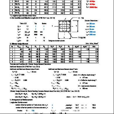
Rc Column Design Bs8110 5n6km
January 2021 0
Column Design - As Per Bs8110 4r4l4x
April 2020 26
Reinforced Concrete Design To Bs8110 4n1m6c
April 2020 59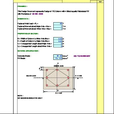
Column Design 4m132j
April 2020 37
2 Piles Cap Design Bs8110 3516t
October 2019 53More Documents from "Mitra Rampersad" 1yn65

3-pile Cap Design 5e4g2o
October 2019 101
Column Design To Bs8110 Template 3366e
October 2019 64
Ppt Bhd 1d613k
December 2020 0
Kks 3u4f58
April 2020 33