Built-up Steel Beam 1k3hf
This document was ed by and they confirmed that they have the permission to share it. If you are author or own the copyright of this book, please report to us by using this report form. Report 2z6p3t
Overview 5o1f4z
& View Built-up Steel Beam as PDF for free.
More details 6z3438
- Words: 701
- Pages: 4
1 DESIGN OF MAIN BEAM Design wind load 0.16 kN/m^2 [As per IS 800- 2007] Analysis: DL = WL thr =
2
0.05 kN/m 2 0.16 kN/m
Purlin spacing = Main beam spacing= Loading on main beam: DL = 0.05 x 4 = WLthr = 0.16 x 4 =
-Thrust pressure (downwards)
1.2 m 4m 0.2 kN/m 0.64 kN/m
-UDL on main beam due to DL -UDL on main beam due to Thrust pressure
*Considering the loads acting on main beam as UDL instead of point loads that are transferred from purlin to main beam. Load Combinations for design: (As per IS 800-2007) 1.5 (DL+WLthr) = 1.40601 kN/m
-Acting downwards
UDL 1.2 m 8m Rf
Re Loading on the main beam and condition Spacing of purlins = No. of purlins =
1.2 m 7
-From the symmetry of the loading, the reaction force from beam are; Re = R f = -For the load case 1.5 (DL+WLthr), downwards 5.62404 kN
Bending Moment: Mmax = 11.248 kN-m
-For the load case 1.5 (DL+WLthr), downwards (Maxm. BM at section of the beam)
1
bf = 80
Trial Section:
tf = 4 BUILT UP SECTION (refer fig.) Grade: E 350 fu= 490 MPa fy=
dw = 150
350 MPa
tw = 4
tf, tw- thickness of flange & web respectively dw- clear depth of the web bf- width of the flange *All dimensions are in mm Sectional properties: A= H= rz=
1240 mm 158 63.0 mm
Zze=
2
3
3
3
3
Zzp=
9.73 kg/m
ry=
16.6 mm 8.6 x103 mm3 0.3421 x106 mm4
Zye=
62.3 x10 mm 4.92 x106 mm4
Iz=
m=
Iy=
Zyp= 71.780 x10 mm Y_ver= 57.887 X_hori= mm Zze,Zye- Elastic section modulus @ major & minor axes respectively
13.40 x103 mm3 10.8065 mm
Zzp,Zyp- Plastic section modulus @ major & minor axes respectively Iz,Iy- Second moment of area @ major & minor axes respectively rz,ry- Radius of gyration @ major & minor axes respectively D,t- Depth & thickness of the section respectively m- mass per unit length of the section Classification of section =√(250/ _ )
For I-sections: Plastic Compact 9.4ε 10.5ε 7.944 8.874 b/tf= 9.500
=
0.8452
Semi-compact 15.7ε 13.269
[ As per Table 2 of IS 800- 2007] b- outstand element of compression flange tf- thickness of the flange
.'. Section is
Semi-compact
2
βb =
0.868
Moment carrying capacity of the section Md- moment carrying capacity of the section
_ = _
_
_
zp- plastic section modulus for the given c/s fbd- design bending compressive stress
Calculation of fbd: _
/
_
=
72.243
h= tf =
154.0 mm 4 mm
h/tf =
h- c/c distace betwn. the flanges
38.50
fcr,b interpolation h/t LLT/r
35 38.5 70 485.5 478.85 72.243 455.4736 80 381.2 374.62 .'. fcr,b = 455.4736004
40 476 371.8 -Table 14 of IS 800- 2007
αLT= 0.49
-For Builtup steel sections
fbd interpolation fy .'. fcr,b 500 455.4736 450 .'. fbd =
350 203.55 195.0455 191.6 194 195.045 MPa
.'. Md =
340 200.9
360 206.2 196.4 -Table 13 (b) of IS 800- 2007
12.148 kN-m
-Moment carrying capacity of the section
Md >
SAFE
Mmax.
Stress Ratio=
0.926
where, M max. is maxm. bending moment in the main beam for the all possible load cases. Shear capacity of the section: Vu,max = 5.62404 kN
-For the load case 1.5 (DL+WL thr), downwards -Maxm. SF at section of the beam
_ =( _ × _ )/(ϒ_ ×√3)
Vd - shear capacity of the section fyw - yield strength of web of the section ϒmo - partial safety factor= 1.1 3
Av -Shear area of the section i.e web area for I-sectn. 2
Av =
600 mm
fyw=
350 MPa .'. Vd=
110.221 kN
0.6 Vd=
66.13 kN
.'. 0.6 Vd >
Vu,max
Hence SAFE
[As per Cl. 8.2.1.2 of IS 800- 2007]
Deflection: Load Combinations for serviceability: 1.0 (DL+WLthr) = 0.937 kN/m Δ_ =(5 _ ^4)/384 Δ_ = Δ_ =
-Acting downwards
-Maxm. deflection at any point in the beam for any possible load case (occuring at the mid-point of the beam)
50.800 mm span/150 =
-So, no reduction in moment carrying capacity is to be made
53.33 mm
Hence OK
4
2
0.05 kN/m 2 0.16 kN/m
Purlin spacing = Main beam spacing= Loading on main beam: DL = 0.05 x 4 = WLthr = 0.16 x 4 =
-Thrust pressure (downwards)
1.2 m 4m 0.2 kN/m 0.64 kN/m
-UDL on main beam due to DL -UDL on main beam due to Thrust pressure
*Considering the loads acting on main beam as UDL instead of point loads that are transferred from purlin to main beam. Load Combinations for design: (As per IS 800-2007) 1.5 (DL+WLthr) = 1.40601 kN/m
-Acting downwards
UDL 1.2 m 8m Rf
Re Loading on the main beam and condition Spacing of purlins = No. of purlins =
1.2 m 7
-From the symmetry of the loading, the reaction force from beam are; Re = R f = -For the load case 1.5 (DL+WLthr), downwards 5.62404 kN
Bending Moment: Mmax = 11.248 kN-m
-For the load case 1.5 (DL+WLthr), downwards (Maxm. BM at section of the beam)
1
bf = 80
Trial Section:
tf = 4 BUILT UP SECTION (refer fig.) Grade: E 350 fu= 490 MPa fy=
dw = 150
350 MPa
tw = 4
tf, tw- thickness of flange & web respectively dw- clear depth of the web bf- width of the flange *All dimensions are in mm Sectional properties: A= H= rz=
1240 mm 158 63.0 mm
Zze=
2
3
3
3
3
Zzp=
9.73 kg/m
ry=
16.6 mm 8.6 x103 mm3 0.3421 x106 mm4
Zye=
62.3 x10 mm 4.92 x106 mm4
Iz=
m=
Iy=
Zyp= 71.780 x10 mm Y_ver= 57.887 X_hori= mm Zze,Zye- Elastic section modulus @ major & minor axes respectively
13.40 x103 mm3 10.8065 mm
Zzp,Zyp- Plastic section modulus @ major & minor axes respectively Iz,Iy- Second moment of area @ major & minor axes respectively rz,ry- Radius of gyration @ major & minor axes respectively D,t- Depth & thickness of the section respectively m- mass per unit length of the section Classification of section =√(250/ _ )
For I-sections: Plastic Compact 9.4ε 10.5ε 7.944 8.874 b/tf= 9.500
=
0.8452
Semi-compact 15.7ε 13.269
[ As per Table 2 of IS 800- 2007] b- outstand element of compression flange tf- thickness of the flange
.'. Section is
Semi-compact
2
βb =
0.868
Moment carrying capacity of the section Md- moment carrying capacity of the section
_ = _
_
_
zp- plastic section modulus for the given c/s fbd- design bending compressive stress
Calculation of fbd: _
/
_
=
72.243
h= tf =
154.0 mm 4 mm
h/tf =
h- c/c distace betwn. the flanges
38.50
fcr,b interpolation h/t LLT/r
35 38.5 70 485.5 478.85 72.243 455.4736 80 381.2 374.62 .'. fcr,b = 455.4736004
40 476 371.8 -Table 14 of IS 800- 2007
αLT= 0.49
-For Builtup steel sections
fbd interpolation fy .'. fcr,b 500 455.4736 450 .'. fbd =
350 203.55 195.0455 191.6 194 195.045 MPa
.'. Md =
340 200.9
360 206.2 196.4 -Table 13 (b) of IS 800- 2007
12.148 kN-m
-Moment carrying capacity of the section
Md >
SAFE
Mmax.
Stress Ratio=
0.926
where, M max. is maxm. bending moment in the main beam for the all possible load cases. Shear capacity of the section: Vu,max = 5.62404 kN
-For the load case 1.5 (DL+WL thr), downwards -Maxm. SF at section of the beam
_ =( _ × _ )/(ϒ_ ×√3)
Vd - shear capacity of the section fyw - yield strength of web of the section ϒmo - partial safety factor= 1.1 3
Av -Shear area of the section i.e web area for I-sectn. 2
Av =
600 mm
fyw=
350 MPa .'. Vd=
110.221 kN
0.6 Vd=
66.13 kN
.'. 0.6 Vd >
Vu,max
Hence SAFE
[As per Cl. 8.2.1.2 of IS 800- 2007]
Deflection: Load Combinations for serviceability: 1.0 (DL+WLthr) = 0.937 kN/m Δ_ =(5 _ ^4)/384 Δ_ = Δ_ =
-Acting downwards
-Maxm. deflection at any point in the beam for any possible load case (occuring at the mid-point of the beam)
50.800 mm span/150 =
-So, no reduction in moment carrying capacity is to be made
53.33 mm
Hence OK
4
Related Documents c2h70

Eurobeam Steel Beam Calculation 403c3v
February 2022 0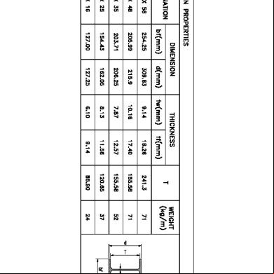
3. Steel Beam Schedule 712p12
November 2022 0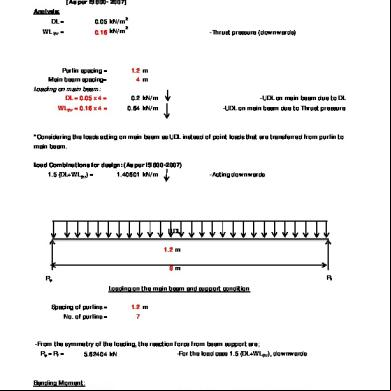
Built-up Steel Beam 1k3hf
December 2019 57
Steel Beam Design 1v203o
November 2019 68
140360310-steel-beam-design.xls 216p21
November 2019 59