A Simple Rotating Loop Between Curved Pole Faces 6z1944
This document was ed by and they confirmed that they have the permission to share it. If you are author or own the copyright of this book, please report to us by using this report form. Report 2z6p3t
Overview 5o1f4z
& View A Simple Rotating Loop Between Curved Pole Faces as PDF for free.
More details 6z3438
- Words: 1,894
- Pages: 31
A Simple Rotating Loop between Curved Pole Faces The simplest rotating dc machine is shown below:
•It consists of a single loop of wire rotating about a fixed axis. •The rotating part is called rotor, and the stationary part is the stator. •The magnetic field for the machine is supplied by the magnetic north and south poles. •Since the air gap is of uniform width, the reluctance is the same everywhere under the pole faces.
EE41 – ELECTROMECHANICAL ENERGY CONVERSION Engr. Elvin D. Dulce
Department of Electrical Engineering, CEAT, UPLB
The Voltage Induced in a Rotating Loop
•If the rotor is rotated, a voltage will be induced in the wire loop. •To determine the total voltage etot on the loop, examine each segment of the loop separately and sum all the resulting voltages. •The voltage on each segment is given by
eind = (v x B) l
EE41 – ELECTROMECHANICAL ENERGY CONVERSION Engr. Elvin D. Dulce
Department of Electrical Engineering, CEAT, UPLB
The Voltage Induced in a Rotating Loop
•SEGMENT ab: eba = (v x B) l = vBl (+ into the page) •SEGMENT bc: ebc = 0 •SEGMENT cd: edc = (v x B) l = vBl (+ out of the page) •SEGMENT da: eda = 0 etotal = 2vBl EE41 – ELECTROMECHANICAL ENERGY CONVERSION Engr. Elvin D. Dulce
Department of Electrical Engineering, CEAT, UPLB
The Voltage Induced in a Rotating Loop
When the loop rotates by 180:
•SEGMENT ab: eab = (v x B) l = vBl (+ out of the page) •SEGMENT bc: ebc = 0 •SEGMENT cd: ecd = (v x B) l = vBl (+ into the page) •SEGMENT da: eda = 0 etotal = -2vBl EE41 – ELECTROMECHANICAL ENERGY CONVERSION Engr. Elvin D. Dulce
Department of Electrical Engineering, CEAT, UPLB
The Voltage Induced in a Rotating Loop
•The graph of the resulting voltage is shown below:
•Alternative way of to express the equation for eind which relates the behavior of larger, real DC machines:
eind
2 0
Under the pole faces
beyond the pole edges •Thus, the voltage generated in the machine is equal to the product of the flux inside the machine and the speed of rotation of the machine, multiplied by a constant representing the mechanical construction of the machine. EE41 – ELECTROMECHANICAL ENERGY CONVERSION Engr. Elvin D. Dulce
Department of Electrical Engineering, CEAT, UPLB
Getting DC voltage out of the Rotating Loop
COMMUTATION is the process of converting the ac voltages and currents in the rotor of a dc machine to dc voltages and currents at its terminals.
EE41 – ELECTROMECHANICAL ENERGY CONVERSION Engr. Elvin D. Dulce
Department of Electrical Engineering, CEAT, UPLB
The Induced Torque in the Rotating Loop
Suppose a battery is now connected to the machine:
EE41 – ELECTROMECHANICAL ENERGY CONVERSION Engr. Elvin D. Dulce
Department of Electrical Engineering, CEAT, UPLB
The Induced Torque in the Rotating Loop
•Force will be induced in each segment of the loop at the instant the switch is closed:
•SEGMENT ab: Fab = i(l x B) = ilB •SEGMENT bc: Fbc = 0 •SEGMENT cd: Fcd = i(l x B) = ilB •SEGMENT da: Fda = 0 2 ind = 2rilB = i ind = 2rilB EE41 – ELECTROMECHANICAL ENERGY CONVERSION Engr. Elvin D. Dulce
= rF sinθ = rilB =0 = rF sinθ = rilB =0 under the pole faces
beyond the pole edges Department of Electrical Engineering, CEAT, UPLB
The Induced Torque in the Rotating Loop
•In general, the torque in any real machine will depend on the same 3 factors:
1. The flux in the machine 2. The current in the machine 3. A constant representing the construction of the machine.
EE41 – ELECTROMECHANICAL ENERGY CONVERSION Engr. Elvin D. Dulce
Department of Electrical Engineering, CEAT, UPLB
Commutation in a Simple Four-Loop DC Machine
•A simple 4 loop, 2 pole dc machine is shown below:
•The 4 loops of this machine are laid into the slots in a special manner. •The “unprimed” end of each loop is the outermost wire in each slot, while the “primed” end of each loop is the innermost wire in the slot directly opposite.
•This machine has 4 complete loops buried in slots carved in the laminated steel of its rotor. •The pole faces of the machine are curved to provide a uniform air-gap width and to give a uniform flux density everywhere under the faces. EE41 – ELECTROMECHANICAL ENERGY CONVERSION Engr. Elvin D. Dulce
Department of Electrical Engineering, CEAT, UPLB
Commutation in a Simple Four-Loop DC Machine
•At t = 0, the 1, 2, 3’ and 4’ ends of the loops are under the north pole face, while the 1’, 2’, 3 and 4 ends are under the south pole face.
•The voltage in each of the 1, 2, 3’ and 4’ ends of the loops is given by: eind = vBl (positive out of page) •The voltage in each of the 1’, 2’, 3 and 4 ends of the loops is given by: eind = vBl (positive into the page)
E = 4e
t = 0
Commutation in a Simple Four-Loop DC Machine
•At t = 45, the 2 and 4’ ends of the loops are under the north pole face, the 2’ and 4 ends are under the south pole face, while the 3, 3’, 1, 1’ ends are beyond the pole edges.
•The voltage in each of the 2 and 4’ ends of the loops is given by: eind = vBl (positive out of page) •The voltage in each of the 2’ and 4 ends of the loops is given by: eind = vBl (positive into the page) EE41 – ELECTROMECHANICAL ENERGY CONVERSION Engr. Elvin D. Dulce
Department of Electrical Engineering, CEAT, UPLB
Commutation in a Simple Four-Loop DC Machine
•At t = 45, the 2 and 4’ ends of the loops are under the north pole face, the 2’ and 4 ends are under the south pole face, while the 3, 3’, 1, 1’ ends are beyond the pole edges.
•The loops 1 and 3 have rotated into the gap between the poles, so the voltage across each of them is zero. •The brushes of the machine are shorting out commutator segments ab and cd. This happens just at the time when the loops between these segments have 0V across them, so shorting out the segments creates no problem.
Commutation in a Simple Four-Loop DC Machine
•At t = 45, the 2 and 4’ ends of the loops are under the north pole face, the 2’ and 4 ends are under the south pole face, while the 3, 3’, 1, 1’ ends are beyond the pole edges.
The total voltage across the brushes is:
E = 2e EE41 – ELECTROMECHANICAL ENERGY CONVERSION Engr. Elvin D. Dulce
t = 45 Department of Electrical Engineering, CEAT, UPLB
Commutation in a Simple Four-Loop DC Machine
•Now, let the rotor continue to turn another 45°. The resulting situation is shown below:
•Here, the 1’, 2, 3, and 4’ ends of the loops are under the north pole face, and the 1, 2’, 3’ and 4 ends of the loops are under the south pole face. •The voltages are still built up out of the page for the ends under the north pole face and into the page for the ends under the south pole face.
E = 4e EE41 – ELECTROMECHANICAL ENERGY CONVERSION Engr. Elvin D. Dulce
t = 90
Department of Electrical Engineering, CEAT, UPLB
Commutation in a Simple Four-Loop DC Machine
•The voltages on loops 1 and 3 have reversed between the 2 pictures (from ωt=0° to ωt=90°), but since their connections have also reversed, the total voltage is still being built up in the same direction as before. •This is the heart of every commutation scheme.
ωt=0° EE41 – ELECTROMECHANICAL ENERGY CONVERSION Engr. Elvin D. Dulce
ωt=90° Department of Electrical Engineering, CEAT, UPLB
Commutation in a Simple Four-Loop DC Machine
•The terminal voltage of this 4-loop DC machine is shown below:
•As the number of loops on the rotor increases, the approximation to a perfect DC voltage continues to get better and better. •COMMUTATION is the process of switching the loop connections on the rotor of a DC machine just as the voltage in the loop switches polarity in order to maintain an essentially constant DC output voltage. EE41 – ELECTROMECHANICAL ENERGY CONVERSION Engr. Elvin D. Dulce
Department of Electrical Engineering, CEAT, UPLB
“Commutation and armature construction in real dc machines” •There are several ways in which the loops on the rotor (armature) can be connected to its commutator segments. •These different connections affect: a. The number of parallel current paths within the rotor b. The output voltage of the rotor c. The number and position of the brushes riding on the commutator segments
“Commutation and armature construction in real dc machines” THE ROTOR COILS •Consist of diamondshaped coils which are inserted into the armature slots. •The number of conductor on a machine’s armature is given by:
Z = 2CNC
Z=# of cond. on rotor C=# of coils on rotor Nc=# of turns per coil EE41 – ELECTROMECHANICAL ENERGY CONVERSION Engr. Elvin D. Dulce
Department of Electrical Engineering, CEAT, UPLB
“Commutation and armature construction in real dc machines” THE ROTOR COILS
EE41 – ELECTROMECHANICAL ENERGY CONVERSION Engr. Elvin D. Dulce
Department of Electrical Engineering, CEAT, UPLB
“Commutation and armature construction in real dc machines” THE ROTOR COILS
“Commutation and armature construction in real dc machines” •Commutator Pitch (YC) – the distance (in number of segments) between the commutator segments to which the two ends of a coil are connected. •Progressive vs. Retrogressive Winding •Progressive – the end of the coil is connected to a commutator segment ahead of the one its beginning is connected to. •Retrogressive - the end of the coil is connected to a commutator segment behind the one its beginning is connected to. If everything else is identical, the direction of rotation of a progressive wound rotor will be opposite to the direction of rotation of a retrogressive wound rotor. •Plex of Windings – the number of complete and independent set of rotor windings (i.e; simplex, duplex, triplex; multiplex) EE41 – ELECTROMECHANICAL ENERGY CONVERSION Engr. Elvin D. Dulce
Department of Electrical Engineering, CEAT, UPLB
“Commutation and armature construction in real dc machines”
“Commutation and armature construction in real dc machines”
EE41 – ELECTROMECHANICAL ENERGY CONVERSION Engr. Elvin D. Dulce
Department of Electrical Engineering, CEAT, UPLB
“Commutation and armature construction in real dc machines”
# of Poles: # of Slots: # of Commutators: Winding Type: Multiplicity: Rotation:
2 8 8 lap simplex progressive
EE41 – ELECTROMECHANICAL ENERGY CONVERSION Engr. Elvin D. Dulce
Department of Electrical Engineering, CEAT, UPLB
“Commutation and armature construction in real dc machines”
EE41 – ELECTROMECHANICAL ENERGY CONVERSION Engr. Elvin D. Dulce
Department of Electrical Engineering, CEAT, UPLB
DC GENERATORS
Main fields in DC generators are supplied by: 1. Electromagnets 2. Permanent magnets EE41 – ELECTROMECHANICAL ENERGY CONVERSION Engr. Elvin D. Dulce
Department of Electrical Engineering, CEAT, UPLB
DC GENERATORS Electromagnets or Field Poles: •Built up of stack of steel laminations having good magnetic qualities fastened together.
Field Coils: •Excited with direct current to provide main flux to the armature.
EE41 – ELECTROMECHANICAL ENERGY CONVERSION Engr. Elvin D. Dulce
Department of Electrical Engineering, CEAT, UPLB
Related Documents c2h70

A Simple Rotating Loop Between Curved Pole Faces 6z1944
December 2021 0
Simple Definition Of Pole Capacity 4cj3n
December 2019 17
A Seminar On Rotating Building 4l2un
November 2019 16
Curved Beams.pdf 6d1gp
December 2021 0
Curved Bridges 5x5g35
December 2020 0
Anatomy Of A Utility Pole h4w59
November 2022 0More Documents from "Elben" 1h5m5d
A Simple Rotating Loop Between Curved Pole Faces 6z1944
December 2021 0
Your Voucher Metrodeal Philippines 440k
November 2019 15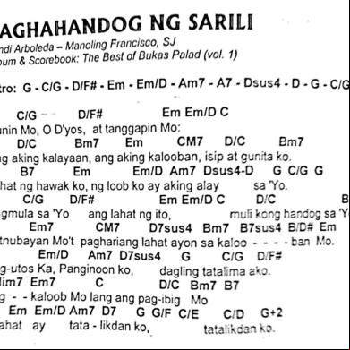
November 2019 63

Panunuluyan 2u5x3l
February 2022 0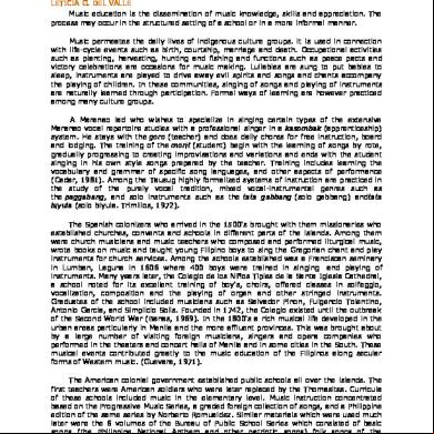
History Of Music Education In The Philippines 3k6g4q
January 2022 0