6 2 Formulae Wave Optics 6q6e25
This document was ed by and they confirmed that they have the permission to share it. If you are author or own the copyright of this book, please report to us by using this report form. Report 2z6p3t
Overview 5o1f4z
& View 6 2 Formulae Wave Optics as PDF for free.
More details 6z3438
- Words: 2,881
- Pages: 12
6.2 WAVE OPTICS Wavefront: A wavelet is the point of disturbance due to propagation of light. A wavefront is the locus of points (wavelets) having the same phase of oscillations. A line perpendicular to a wavefront is called a ‘ray’.
Spherical Wavefront from a point source
Cylindrical Wavefront from a linear source
•
Plane Wavefront
Pink Dots – Wavelets Blue Envelope– Wavefront Red Line – Ray
Huygens’ Construction or Huygens’ Principle of Secondary Wavelets:
. .
.
S•
. .
.
. . . New Wavefront (Spherical)
(Wavelets - Red dots on the wavefront)
• •
. . . . . . . .
New Wavefront (Plane)
Each point on a wavefront acts as a fresh source of disturbance of light. The new wavefront at any time later is obtained by taking the forward envelope of all the secondary wavelets at that time.
Note: Backward wavefront is rejected. Why? Amplitude of secondary wavelet is proportional to ½ (1+cosθ). Obviously, for the backward wavelet θ = 180° and (1+cos θ) is 0.
Laws of Reflection at a Plane Surface (On Huygens’ Principle): If c be the speed of light, t be the time taken by light to go from B to C or A to D or E to G through F, then
N
E
i
G
i
X t = t =
+
D
B
EF FG t = + c c AF sin i c
N
A
FC sin r c
r
r
Y
C
F
AB – Incident wavefront CD – Reflected wavefront XY – Reflecting surface
AC sin r + AF (sin i – sin r)
c For rays of light from different parts on the incident wavefront, the values of AF are different. But light from different points of the incident wavefront should take the same time to reach the corresponding points on the reflected wavefront. So, t should not depend upon AF. This is possible only if sin i – sin r = 0. i.e. sin i = sin r or i=r
Laws of Refraction at a Plane Surface (On Huygens’ Principle): If c be the speed of light, t be the time taken by light to go from B to C or A to D or E to G through F, then
N B i
t =
EF FG + c v
t =
AF sin i c
+
t =
AC sin r v
+ AF (
N Rarer
c, µ1
E
i
X
C
F
r
A
G
FC sin r v
D
sin i sin r ) c v
Y
Denser
r
v, µ2
AB – Incident wavefront CD – Refracted wavefront XY – Refracting surface
For rays of light from different parts on the incident wavefront, the values of AF are different. But light from different points of the incident wavefront should take the same time to reach the corresponding points on the refracted wavefront. So, t should not depend upon AF. This is possible only if sin i sin r =0 c v
or
sin i sin r = c v
or
sin i sin r
=
c v
= µ
Interference of Waves: Bright Band
E1 + E2 E1
Dark Band
S1
E2
S2
•
Bright Band
• Dark Band
Constructive Interference E = E1 + E2 E1
Bright Band
E1 - E2 E2
Crest Trough Bright Band Dark Band
Destructive Interference E = E1 - E2 1st Wave (E1) 2nd Wave (E2) Resultant Wave Reference Line
The phenomenon of one wave interfering with another and the resulting redistribution of energy in the space around the two sources of disturbance is called interference of waves.
Theory of Interference of Waves: E1 = a sin ωt E2 = b sin (ωt + Φ)
The waves are with same speed, wavelength, frequency, time period, nearly equal amplitudes, travelling in the same direction with constant phase difference of Φ. ω is the angular frequency of the waves, a,b are the amplitudes and E1, E2 are the instantaneous values of Electric displacement.
Applying superposition principle, the magnitude of the resultant displacement of the waves is E = E1 + E2 E = a sin ωt + b sin (ωt + Φ) E = (a + b cos Φ) sin ωt + b sin Φ cos ωt Putting a + b cos Φ = A cos θ b sin Φ = A sin θ We get
E = A sin (ωt + θ)
(where E is the resultant displacement, A is the resultant amplitude and θ is the resultant phase difference)
A sin θ b sin Φ
A Φ
A = √ (a2 + b2 + 2ab cos Φ)
tan θ =
b sin Φ a + b cos Φ
b
θ
a b cos Φ
A cos θ
A = √ (a2 + b2 + 2ab cos Φ) Intensity I is proportional to the square of the amplitude of the wave. So, I α A2
i.e. I α (a2 + b2 + 2ab cos Φ)
Condition for Constructive Interference of Waves: For constructive interference, I should be maximum which is possible only if cos Φ = +1. i.e. Φ = 2nπ
where n = 0, 1, 2, 3, …….
Corresponding path difference is ∆ = (λ / 2 π) x 2nπ Imax α (a + b)2
∆=nλ
Condition for Destructive Interference of Waves: For destructive interference, I should be minimum which is possible only if cos Φ = - 1. i.e. Φ = (2n + 1)π
where n = 0, 1, 2, 3, …….
Corresponding path difference is ∆ = (λ / 2 π) x (2n + 1)π ∆ = (2n + 1) λ / 2
Iminα (a - b)2
Comparison of intensities of maxima and minima: Imax α (a + b)2 Imin α (a - b)2 (a + b)2
Imax Imin
=
Imax Imin
(a - b)2
(a/b + 1)2 =
(a/b - 1)2
(r + 1)2 =
where r = a / b
(r - 1)2
(ratio of the amplitudes)
Relation between Intensity (I), Amplitude (a) of the wave and Width (w) of the slit: I α a2
I1
a α √w
I2
(a1)2
=
(a2)2
=
w1 w2
Young’s Double Slit Experiment:
S
• Single Slit
Double Slit P y
S1
•
d/2
d
S
d/2 S2
Screen
O
D
The waves from S1 and S2 reach the point P with some phase difference and hence path difference ∆ = S2P – S1P S2P2 – S1P2 = [D2 + {y + (d/2)}2] - [D2 + {y - (d/2)}2] (S2P – S1P) (S2P + S1P) = 2 yd ∆ (2D) = 2 yd
∆ = yd / D
Positions of Bright Fringes: For a bright fringe at P, ∆ = yd / D = nλ where n = 0, 1, 2, 3, …
y=nDλ/d For n = 0, For n = 1, For n = 2, For n = n,
y0 = 0 y1 = D λ / d y2 = 2 D λ / d …… yn = n D λ / d
Positions of Dark Fringes: For a dark fringe at P, ∆ = yd / D = (2n+1)λ/2 where n = 0, 1, 2, 3, … y = (2n+1) D λ / 2d For n = 0, For n = 1, For n = 2, For n = n,
y0’ = D λ / 2d y1’ = 3D λ / 2d y2’ = 5D λ / 2d ….. yn’ = (2n+1)D λ / 2d
Expression for Dark Fringe Width:
Expression for Bright Fringe Width:
βD = yn – yn-1 = n D λ / d – (n – 1) D λ / d =Dλ/d
βB = yn’ – yn-1’ = (2n+1) D λ / 2d – {2(n-1)+1} D λ / 2d =Dλ/d
The expressions for fringe width show that the fringes are equally spaced on the screen.
Distribution of Intensity: Intensity
y
0
y
Suppose the two interfering waves have same amplitude say ‘a’, then Imax α (a+a)2 i.e. Imax α 4a2 All the bright fringes have this same intensity. Imin = 0 All the dark fringes have zero intensity.
Conditions for sustained interference:
• • •
The two sources producing interference must be coherent.
•
The sources must be monochromatic. Otherwise, the fringes of different colours will overlap.
•
The two waves must be having same amplitude for better contrast between bright and dark fringes.
The two interfering wave trains must have the same plane of polarisation. The two sources must be very close to each other and the pattern must be observed at a larger distance to have sufficient width of the fringe. (D λ / d)
Colours in Thin Films: It can be proved that the path difference between the light partially reflected from PQ and that from partially transmitted and then reflected from RS is
A i P
∆ = 2µt cos r
O
For the rays OA and BC to interfere constructively (Bright fringe), the path difference must be (n + ½) λ So, 2µt cos r = (n + ½) λ
R
Q
B r
Since there is a reflection at O, the ray OA suffers an additional phase difference of π and hence the corresponding path difference of λ/2.
C
µ t S
For the rays OA and BC to interfere destructively (Dark fringe), the path difference must be nλ So, 2µt cos r = n λ
When white light from the sun falls on thin layer of oil spread over water in the rainy season, beautiful rainbow colours are formed due to interference of light.
Diffraction of light at a single slit: 1) At an angle of diffraction θ = 0°:
A
d
0 1 2 3 4 5 6 7 8 9 10 11 12
θ = 0°
• • • • • • • • • • • • •
•O
Bright
D
B Plane Wavefront Slit
Screen The wavelets from the single wavefront reach the centre O on the screen in same phase and hence interfere constructively to give Central or Primary Maximum (Bright fringe). 2) At an angle of diffraction θ = θ1: The slit is imagined to be divided into 2 equal halves. A
• • • • • • • • • • • • •
0 1 2 3 4 5 6 7 8 λ/2 9 10 11 12
θ1
• P1 Dark θ
N
•O
Bright
θ
B λ Plane Wavefront Slit Screen The wavelets from the single wavefront diffract at an angle θ1 such that BN is λ and reach the point P1. The pairs (0,6), (1,7), (2,8), (3,9), (4,10), (5,11) and (6,12) interfere destructively with path difference λ/2 and give First Secondary Minimum (Dark fringe).
3) At an angle of diffraction θ = θ2: The slit is imagined to be divided into 4 equal parts.
A 0 1 2 3 4 5 6 7 8 9 10 11 12
• • • • λ/2 • • θ • • λ • • 3λ/2 • • θ •
B Plane Wavefront Slit
θ
• P2
Dark
• P1’ • P1
Dark
•O
Bright
N
2λ Screen
The wavelets from the single wavefront diffract at an angle θ2 such that BN is 2λ and reach the point P2. The pairs (0,3), (1,4), (2,5), (3,6), (4,7), (5,8), (6,9), (7,10), (8,11) and (9,12) interfere destructively with path difference λ/2 and give Second Secondary Minimum (Dark fringe).
4) At an angle of diffraction θ = θ1’: The slit is imagined to be divided into 3 equal parts. A
• • • • • • • • • • • • •
0 1 2 3 4 5 λ/2 6 7 8 9 λ 10 11 12
• P2 • P1’
θ1 ’
Bright
• P1 θ1 ’
•O
Dark
Bright
N θ1 ’ B Plane 3λ/2 Wavefront Slit Screen The wavelets from the single wavefront diffract at an angle θ1’ such that BN is 3λ/2 and reach the point P1’. The pairs (0,8), (1,9), (2,10), (3,11) and (4,12) interfere constructively with path difference λ and (0,4), (1,5), (2,6), …… and (8,12) interfere destructively with path difference λ/2. However due to a few wavelets interfering constructively First Secondary Maximum (Bright fringe) is formed.
Theory: The path difference between the 0th wavelet and 12th wavelet is BN. If ‘θ’ is the angle of diffraction and ‘d’ is the slit width, then BN = d sin θ To establish the condition for secondary minima, the slit is divided into 2, 4, 6, … equal parts such that corresponding wavelets from successive regions interfere with path difference of λ/2. Or for nth secondary minimum, the slit can be divided into 2n equal parts. Since θn is very small, d θn = nλ θn = nλ / d (n = 1, 2, 3, ……)
For θ1, d sin θ1 = λ For θ2, d sin θ2 = 2λ For θn, d sin θn = nλ
To establish the condition for secondary maxima, the slit is divided into 3, 5, 7, … equal parts such that corresponding wavelets from alternate regions interfere with path difference of λ. Or for nth secondary minimum, the slit can be divided into (2n + 1) equal parts. For θ1’, d sin θ1’ = 3λ/2 For θ2’, d sin θ2’ = 5λ/2 For θn’, d sin θn’ = (2n + 1)λ/2
Since θn’ is very small, d θn’ = (2n + 1)λ / 2 θn’ = (2n + 1)λ / 2d
(n = 1, 2, 3, ……)
Width of Central Maximum: A
d
• • • • • • • • • • • • •
0 1 2 3 4 5 6 7 8 λ/2 9 10 11 12
θ
• P1 Dark y1 θ D
N
•O
Bright
θ
B λ Plane Wavefront Slit tan θ1 = y1 / D or θ1 = y1 / D (since θ1 is very small) d sin θ1 = λ or θ1 = λ / d (since θ1 is very small)
Screen y1 = D λ / d Since the Central Maximum is spread on either side of O, the width is β0 = 2D λ / d
Fresnel’s Distance: Fresnel’s distance is that distance from the slit at which the spreading of light due to diffraction becomes equal to the size of the slit. y1 = D λ / d At Fresnel’s distance, y1 = d and D = DF So, DF λ / d = d or DF = d2 / λ If the distance D between the slit and the screen is less than Fresnel’s distance DF, then the diffraction effects may be regarded as absent. So, ray optics may be regarded as a limiting case of wave optics.
Polarisation of Transverse Mechanical Waves:
Narrow Slit
Transverse disturbance (up and down)
Narrow Slit
90°
Transverse disturbance (up and down)
Narrow Slit
Polarisation of Light Waves: Light waves are electromagnetic waves with electric and magnetic fields oscillating at right angles to each other and also to the direction of propagation of wave. Therefore, the light waves can be polarised. Optic Axis
• • • • • • Unpolarised light
Plane Polarised light
Plane Polarised light
Polariser
Analyser
Tourmaline Crystal
Tourmaline Crystal
90°
• • • • • •
No light Plane Polarised light
Unpolarised light
90°
• • • • • • Unpolarised light
Polariser Plane of Vibration
Analyser Plane of Polarisation
Plane Polarised light
Malus’ Law: When a beam of plane polarised light is incident on an analyser, the intensity I of light transmitted from the analyser varies directly as the square of the cosine of the angle θ between the planes of transmission of analyser and polariser. I α cos2 θ
a a sin θ
If a be the amplitude of the electric vector transmitted by the polariser, then only the component a cos θ will be transmitted by the analyser.
a cos θ P A
Intensity of transmitted light from the analyser is or
I = k (a cos θ)2 I = k a2 cos2 θ 2
I = I0 cos θ (where I0 = k a2 is the intensity of light transmitted from the polariser)
θ
Case I : When θ = 0° or 180°, I = I0 Case II : When θ = 90°, I=0 Case III: When unpolarised light is incident on the analyser the intensity of the transmitted light is one-half of the intensity of incident light. (Since average value of cos2θ is ½)
Polarisation by Reflection and Brewster’s Law: The incident light wave is made of parallel vibrations (π – components) on the plane of incidence and perpendicular vibrations (σ – components : perpendicular to plane of incidence). At a particular angle θP, the parallel components completely refracted whereas the perpendicular components partially get refracted and partially get reflected. i.e. the reflected components are all in perpendicular plane of vibration and hence plane polarised. The intensity of transmitted light through the medium is greater than that of plane polarised (reflected) light.
• • • •
• • • •
θP
90° r
θP + r = 90° aµb
=
aµb
=
µ
• •
b
•
•
or
r = 90° - θP
sin θP sin r sin θP sin 90° - θP
aµb
a
= tan θP
Related Documents c2h70

6 2 Formulae Wave Optics 6q6e25
December 2021 0
Physics Wave Optics Mcq 1314j
December 2021 0
Wave Optics Notes 1c6p2m
November 2022 0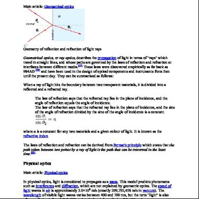
Differences Between Ray Optics And Wave Optics 94t5n
December 2019 36
November 2019 36

Half Wave Potential 2 o172v
December 2019 35More Documents from "Nathanian" 395d1r

Unit 8 Atomic Fluorescence Spectrometry 552n6h
December 2019 36
Unit 9 Applications Of Polarography, Amperometric Titrations And Voltammetry 1l4w6d
October 2019 74
Experiment No 4 Flow Measurements 1f4d2b
December 2019 27
Double Pipe Heat Exchanger - Ss 1j16l
April 2021 0
Unit 2 Evaluation Of Analytical Data I 5471h
December 2019 39