3.1.2.7 Packet Tracer - Investigating A Vlan Implementation Instructions.pdf 2y4o54
This document was ed by and they confirmed that they have the permission to share it. If you are author or own the copyright of this book, please report to us by using this report form. Report 2z6p3t
Overview 5o1f4z
& View 3.1.2.7 Packet Tracer - Investigating A Vlan Implementation Instructions.pdf as PDF for free.
More details 6z3438
- Words: 1,025
- Pages: 4
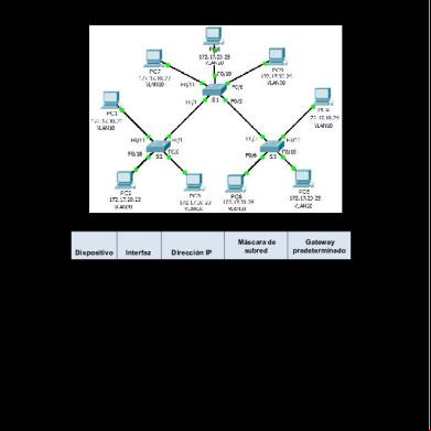
Packet Tracer – Investigating a VLAN Implementation Topology
Addressing Table Device
Interface
IP Address
Subnet Mask
Default Gateway
S1
VLAN 99
172.17.99.31
255.255.255.0
N/A
S2
VLAN 99
172.17.99.32
255.255.255.0
N/A
S3
VLAN 99
172.17.99.33
255.255.255.0
N/A
PC1
NIC
172.17.10.21
255.255.255.0
172.17.10.1
PC2
NIC
172.17.20.22
255.255.255.0
172.17.20.1
PC3
NIC
172.17.30.23
255.255.255.0
172.17.30.1
PC4
NIC
172.17.10.24
255.255.255.0
172.17.10.1
PC5
NIC
172.17.20.25
255.255.255.0
172.17.20.1
PC6
NIC
172.17.30.26
255.255.255.0
172.17.30.1
PC7
NIC
172.17.10.27
255.255.255.0
172.17.10.1
PC8
NIC
172.17.20.28
255.255.255.0
172.17.20.1
PC9
NIC
172.17.30.29
255.255.255.0
172.17.30.1
© 2013 Cisco and/or its s. All rights reserved. This document is Cisco Public.
Page 1 of 4
Packet Tracer – Investigating a VLAN Implementation
Objectives Part 1: Observe Broadcast Traffic in a VLAN Implementation Part 2: Observe Broadcast Traffic without VLANs Part 3: Complete Reflection Questions
Background In this activity, you will observe how broadcast traffic is forwarded by the switches when VLANs are configured and when VLANs are not configured.
Part 1: Observe Broadcast Traffic in a VLAN Implementation Step 1: Ping from PC1 to PC6. a. Wait for all the link lights to turn to green. To accelerate this process, click Fast Forward Time located in the bottom yellow tool bar. b. Click the Simulation tab and use the Add Simple PDU tool. Click on PC1, and then click on PC6. c.
Click the Capture/Forward button to step through the process. Observe the ARP requests as they traverse the network. When the Buffer Full window appears, click the View Previous Events button.
d. Were the pings successful? Why?
No, it is because the ping sent from PC1, went to PC4 as they shared the same VLAN. It would have worked if PC6 was on the same VLAN with PC1. e. Look at the Simulation , where did S3 send the packet after receiving it?
PC4 instead of PC6 In normal operation, when a switch receives a broadcast frame on one of its ports, it forwards the frame out all other ports. Notice that S2 only sends the ARP request out Fa0/1 to S1. Also notice that S3 only sends the ARP request out F0/11 to PC4. PC1 and PC4 both belong to VLAN 10. PC6 belongs to VLAN 30. Because broadcast traffic is contained within the VLAN, PC6 never receives the ARP request from PC1. Because PC4 is not the destination, it discards the ARP request. The ping from PC1 fails because PC1 never receives an ARP reply.
Step 2: Ping from PC1 to PC4. a. Click the New button under the Scenario 0 dropdown tab. Now click on the Add Simple PDU icon on the right side of Packet Tracer and ping from PC1 to PC4. b. Click the Capture/Forward button to step through the process. Observe the ARP requests as they traverse the network. When the Buffer Full window appears, click the View Previous Events button. c.
Were the pings successful? Why? Yes, it is because all PCs share the same VLAN
d. Examine the Simulation . When the packet reached S1, why does it also forward the packet to PC7? It is because PC7 shares the same VLANs as PC1 and PC4.
© 2013 Cisco and/or its s. All rights reserved. This document is Cisco Public.
Page 2 of 4
Packet Tracer – Investigating a VLAN Implementation
Part 2: Observe Broadcast Traffic without VLANs Step 1: Clear the configurations on all three switches and delete the VLAN database. a. Return to Realtime mode. b. Delete the startup configuration on all 3 switches. What command is used to delete the startup configuration of the switches? erase startup-config c.
Where is the VLAN file stored in the switches? nvram
d. Delete the VLAN file on all 3 switches. What command deletes the VLAN file stored in the switches?
no vlan <...> to disable, "delete flash:vlan.dat" for decision
Step 2: Reload the switches. Use the reload command in privileged EXEC mode to reset all the switches. Wait for the entire link to turn green. To accelerate this process, click Fast Forward Time located in the bottom yellow tool bar.
Step 3: Click Capture/Forward to send ARP requests and pings. a. After the switches reload and the link lights return to green, the network is ready to forward your ARP and ping traffic. b. Select Scenario 0 from the drop down tab to return to Scenario 0. c.
From Simulation mode, click the Capture/Forward button to step through the process. Notice that the switches now forward the ARP requests out all ports, except the port on which the ARP request was received. This default action of switches is why VLANs can improve network performance. Broadcast traffic is contained within each VLAN. When the Buffer Full window appears, click the View Previous Events button.
Part 3: Complete Reflection Questions 1. If a PC in VLAN 10 sends a broadcast message, which devices receive it?
PC1, PC4, PC7 2. If a PC in VLAN 20 sends a broadcast message, which devices receive it?
PC2, PC5, PC8 3. If a PC in VLAN 30 sends a broadcast message, which devices receive it?
PC3, PC6, PC9 4. What happens to a frame sent from a PC in VLAN 10 to a PC in VLAN 30?
It cannot received data 5. In of ports, what are the collision domains on the switch?
Switch 6. In of ports, what are the broadcast domains on the switch?
1 lp Broadcast of 1 port switch
© 2013 Cisco and/or its s. All rights reserved. This document is Cisco Public.
Page 3 of 4
Packet Tracer – Investigating a VLAN Implementation
Suggested Scoring Rubric Activity Section Part 1: Observe Broadcast Traffic in a VLAN Implementation
Question Location
Possible Points
Step 1d
6
Step 1e
5
Step 2c
6
Step 2d
5
Part 1 Total Part 2: Observe Broadcast Traffic without VLANs
Part 3: Complete Reflection Questions
22
Step 1b
6
Step 1c
6
Step 1d
6
Part 2 Total
18
1
10
2
10
3
10
4
10
5
10
6
10
Part 3 Total
60
Total Score
100
© 2013 Cisco and/or its s. All rights reserved. This document is Cisco Public.
Earned Points
Page 4 of 4
Related Documents c2h70
Ennio Torres 3.1.2.7 Packet Tracer - Investigating A Vlan Implementation Instructions 3c4h1f
September 2021 0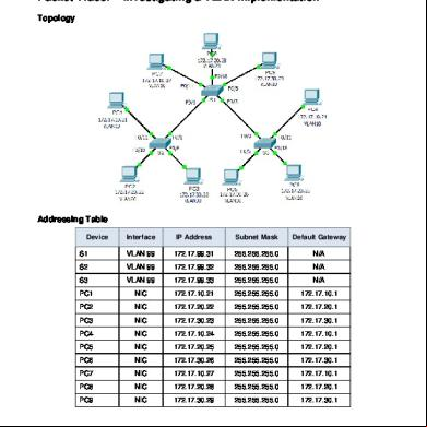
3.1.2.7 Packet Tracer - Investigating A Vlan Implementation Instructions.pdf 2y4o54
November 2019 82
3.1.2.7 Packet Tracer - Investigating A Vlan Implementation Instructions 3g3e1j
December 2019 51
3.1.2.7 Packet Tracer - Investigating A Vlan Implementation Instructions123 3f5i6m
December 2021 0
Configuracion Vlan Packet Tracer 2v3b5f
November 2019 54
3.2.4.7 Packet Tracer - Troubleshooting A Vlan Implementation - Scenario 1 Instructions m1o62
December 2019 68More Documents from "Athena Buenavista" 3lh49
3.1.2.7 Packet Tracer - Investigating A Vlan Implementation Instructions.pdf 2y4o54
November 2019 82
Experiment 1 Marble Race (1) 4jd2j
July 2022 0
Shareable - Strong Curves Spreadsheets 3w5w2e
November 2022 0
Lab.-report-1.docx 4a4732
December 2019 37
Ay Lab Chemistry 5m1e5a
December 2019 36